Abstract
This study focuses on numerical solution to the Brinkman equation with mixed Dirichlet–Neumann boundary conditions utilizing isogeometric analysis (IGA) based on non-uniform rational B-splines (NURBS) within the Galerkin method framework. The authors suggest using different choices of compatible NURBS spaces, which may be considered a generalization of traditional finite element spaces for velocity and pressure approximation. In order to investigate the numerical properties of the suggested elements, two numerical experiments based on a square and a quarter of an annulus are discussed. The preliminary results for the Stokes problem are presented in References.
Keywords:
Brinkman; convergence; finite element; isogeometric analysis; Nédélec; NURBS; Raviart–Thomas; Taylor–Hood MSC:
65N30; 65N15; 65G99; 76D07; 76D99
1. Introduction
Hughes et al. recently developed a computational technique known as isogeometric analysis (IGA) (see [1,2,3,4]), which combines computer-aided design (CAD) and finite element analysis (FEA). The same functions that describe the computational domain in a CAD system are used in IGA to represent the solution. IGA is accurate and effective, and is a novel numerical technique used to discretize the wide range of problems of partial differential equations (PDEs). Additionally, IGA provides benefits for numerically approximating high-order PDEs using the traditional Galerkin formulation because it uses a globally smooth foundation. In particular, we refer to NURBS-based IGA because of the wide use of NURBS in CAD technology, and especially for the mathematical properties of these basic functions, for CAD models suitable for analysis. Another advantage of IGA is the use the same initial geometry throughout mesh refinement (for more details, see [4,5,6,7,8,9,10]).
When fissures, bulges, or channels exist in a porous matrix, the Brinkman system controls the viscous fluid in these types of inhomogeneous mediums. This system is mathematically described as a superposition of the Stokes and Darcy systems. The Brinkman problem is represented as a system of partial differential equations with a saddle point structure (for more on this type of problem, see [11,12,13,14,15]). As stated in [16], it is difficult to develop approximations using finite elements that behave consistently well across the spectrum of regimes (dominated by Stokes or Darcy); a collection of representative references includes [17,18,19,20,21,22,23,24,25,26,27,28].
In this study, we examine the ability of the IGA method to solve Brinkman flow problems. When discretizing the Brinkman problem, the velocity and pressure spaces must satisfy the inf-sup condition (or LBB) to ensure discretization that is free of blocking and spurious oscillations [1,2,29,30,31]. B-splines or NURBS on structured meshes provide flexibility in the construction of inf-sup stable- and pressure-velocity spaces with arbitrary ordering and various regularities in the context of IGA. Utilizing three significant families of isogeometric mixed elements, we examine the performance of IGA in mixed formulation elements: Taylor–Hood [1,2,32], Nédélec [1] and Raviart–Thomas [1,3]. Previous studies have explored the application of mixed isogeometric analysis in saddle point problems and fluid mechanics. The stability of the Stokes problem for these three families has been proven in [1,2,29]. Raviart–Thomas elements were used in [3] to solve the generalized Stokes problem, where stability and error estimates were established using this type of element. Additionally [33,34,35,36,37], investigated the use of Raviart–Thomas elements for the Navier–Stokes equations in both steady and unsteady cases, where stability and approximation estimation were established, and an a posteriori error estimate was provided.
This passage describes a research paper that presents a numerical study and comparison of different families of elements that are used to solve a Brinkman problem. The analysis of the Brinkman problem uses divergence-conforming B-splines, which can be understood as smooth generalizations of Raviart–Thomas elements, and is discussed in reference [3]. This paper extends the Galerkin Isogeometric Analysis (GIA) approach by applying smooth generalizations of Taylor–Hood and Nédélec elements in the context of NURBS functions and presenting a comparison between these compatible families. Our study provides valuable information about the capabilities of these families of elements.
This paper is organized into several sections. Section 2 provides preliminary information about splines and Non-Uniform Rational B-Splines (NURBS). Section 3 introduces mixed isogeometric spaces. Section 4 describes the discretization of the Brinkman equation using the NURBS-based finite element method. Finally, in Section 5, two numerical experiments based on a square and a quarter of an annulus are discussed.
2. NURBS and Preliminaries Results
In this section, definitions and notations related to B-splines and NURBS are presented, and more detailed descriptions can be found in [6,9,38,39,40,41,42] and the references therein. In the context of B-splines/NURBS, an additional domain takes into account the domain of parametric splines (see Figure 1), as opposed to finite element analysis, in which only two domains are used; the first is reference and the second is physical Ω. We follow this requirement and present an overview of the characteristics of spline-based discrete approximation spaces in the following.

Figure 1.
Domains of Isogeometric Analysis: is the reference domain, is the parametric domain and Ω is the physical domain defined by the parameterization F as an image of .
B-Spline and NURBS Functions
Assuming that p and n represent two positive integers, the knots vector is defined as:
where is the ordered sequence of the real numbers, and is called the ith knot.
The univariate B-spline basis function for a given knots vector , can be built using the Cox–de Boor formulation (see [6]) for
and for
A spline curve of order in two dimensions is a linear combination of the control points and the B-spline basis functions as follows:
Now, let us introduce the vector of knots without repetitions and the corresponding vector of knots multiplicities . The knots vector is said to be open if . At each point , the B-spline basis functions have continuous derivatives.
The univariate spline space in the parametric domain, spanned by the B-splines , is denoted as:
Let and be two B-splines associated with the knots vector and respectively. The multivariate spline space in the parametric domain , which will be referred to as a patch, is defined using the tensor product.
where .
The 1-dimensional NURBS basis functions are introduced as:
where is the weight that was given to the ith control point, which cannot be negative. A NURBS curve of order in two dimensions is a linear combination of the control points and the NURBS basis functions, i.e.,
The univariate NURBS space in the parametric domain spanned by the NURBS basis functions is denoted as:
Remark 1.
The NURBS basis functions satisfy the following proprieties:
- 1.
- Non-negativity: .
- 2.
- Partition of unity: .
- 3.
- Let be the multiplicity of the value of in the knot vector; is times continuously differentiable over a knot .
- 4.
- if .
Let and be two NURBS basis functions associated with knot vectors and respectively. The mesh associated with the knot vectors and is a partition of into rectangles.
We set the global mesh size as:
The multivariate NURBS space in the parametric domain is defined as:
where ; note that the weight is not defined using the tensor product.
The NURBS geometrical map is then provided as follows:
where refers to the control points. With the piecewise smooth inverse, the family of mesh is naturally generated by F on the physical domain, for example,
where is the pre-mage of by F, the global mesh size is defined as follows:
where .
The NURBS space on represents a push-forward of the space of NURBS on the parametric domain (patch) .
3. Isogeometric Spaces
It is essential that the discrete condition inf-sup be respected before putting the description of our problem into action. Here, we follow the main points of article [1], which proposed three space spline configurations that are variations of known stable spaces for traditional finite elements: Taylor–Hood likes NURBS (TH), Nédélec likes NURBS (NE) and Raviart–Thomas likes NURBS (RT). This section provides a summary of their definitions and properties; for more information, see [29].
3.1. Taylor–Hood Space
The Raviart–Thomas (RT) NURBS spaces are described as
The pressure and velocity are defined with the same regularity on the same knot mesh. The two velocity components are defined in the same space. One order lower than the velocity space is the pressure space. As a result, the velocity space has one more knot than the pressure space; hence, we additionally need a constrained discrete velocity space to handle the no-penetration boundary condition.
The space is spanned by:
where is the th canonical basis vector of , and is then spanned by:
We assume that in , the space is rewritten in simple notation as:
The space is spanned as:
In the simple notation, we rewrite the pressure space as:
where
The Taylor–Hood isogeometric spaces in the physical domain are:
We will also consider the pressure space as:
3.2. Raviart–Thomas
The Raviart–Thomas (RT) NURBS spaces are described as:
The space is spanned by:
For the constraint discrete velocity space, we will also assume that:
where is the th canonical basis vector of , and is then spanned by:
The velocity space is rewritten as:
where:
as , the basis for is (23) and its dimension is denoted by . The Raviart–Thomas isogeometric spaces in the physical domain are:
we used a Piola transform, such as a push-forward for , to assure inf-sup stability [1]. We also consider, in the case of our problem, the pressure space as:
3.3. Nédélec Spaces
The Nédélec (NL) NURBS spaces are defined as:
For the constraint discrete velocity space, we will also assume that:
The space is spanned by:
where is the th canonical basis vector of , and the space is then spanned by:
For simplicity of notation, we rewrite as:
where .
The pressure space is represented as:
By using a similar notation to the above, we write as:
where:
The Nédélec isogeometric spaces in the physical domain are:
We will also consider the pressure space as:
4. The Brinkman Problem
4.1. Formulation Variation of the Brinkman Problem
Let be bounded open, given by the NURBS parameterization F, and (), with defined by the F-image of collection of faces of . The Brinkman equations explain the flow through a porous medium presented by the system.
This is subject to the boundary conditions:
In these equations, p and v represent the pressure and velocity fields, respectively. with p belonging to the space . We assume that is a given source . The fluid under consideration defined by the Newtonian fluid viscosity, the functions , and the physical dynamic viscosity . We impose a null mean value of the pressure field over the entire domain to assure the uniqueness of , i.e.,
presents the permeability of the reservoir. To guarantee the existence of the weak solution, we assume that there exist two constants, , such that is a tensor satisfying the following inequality:
and we assume that . Using, we determine that the subspace of the standard Sobolev space makes all functions vanish on the boundary . We present
as the velocity space and
as the pressure space.
The weak formulation of the Brinkman system (45)–(47) enables us to find , such that:
where and are the bilinear forms defined by:
and is the continuous function:
We equip the spaces and with the norms
and
Theorem 1.
Problem (51) has a unique weak solution .
4.2. Approximate Formulation of the Brinkman Problem
In its original form, IGA entails using a Galerkin formulation and a finite-dimensional subspace of that is spanned by the same set of B-Splines/NURBS basis functions as those characterizing the geometry used to find an approximate solution to (45) and (46). As a result, we present the functional spaces and . Where and are defined using multivariate NURBS functions that were introduced in Section 3. The IGA formulation then reads: Find such that:
To define the corresponding linear algebraic system, we use a set of vector-valued basis functions and for the spaces and , respectively, so that:
where and are the dimensions of the discrete spaces of velocity and of pressure , respectively.
By using the bilinear proprieties of and , we obtain the linear system:
where , , , , and
5. Numerical Results
In this section, we perform numerical verification of our chosen elements using two example tests with exact solutions, with the first one in a square domain and the second one in an annulus domain. Then, we solve our problem for two-dimensional flow and represent well-established benchmark problems, for which we compare the results between the three families of elements studied in this paper.
We want to highlight that, in the NURBS-based IGA framework, the two-dimensional lid-driven flow in a quarter of an annulus benefits from the exact geometric representation provided by NURBS. This is in contrast to standard FE methods. For numerical simulation in Matlab, based on the IGA library GeoPDEs [43], the regularity is assumed equal to .
The graphs of the error are presented on a log–log scale, and in this work, the error and error are defined as:
where is an exact solution and is an approximated solution to our problem.
We use the following formula:
where defines the - or -norm, to demonstrate the convergence rate.
5.1. The Brinkman Problem on the Unit Square
In order to test the accuracy and reliability of the compatible spaces considered, in this first example, we consider the parametric domain , by using the manufactured solution presented in [26]. The exact velocity u and exact pressure p of the Brinkman system (45) and (46) are given below,
it is easy to check that and . with the highly varying permeability equal to , where is a given constant. The values of are plotted in Figure 2 for The boundary conditions considered in this test are:
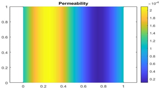
Figure 2.
Permeability.
The vector fields and pressure contours corresponding IGA solutions in three types of element spaces are presented in Figure 3 and Figure 4, with the domain discretized using a 16 × 32 mesh.
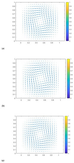
Figure 3.
Vector fields of approximate solutions for three families: approximate NDL solution (a), approximate RT solution (b), approximate TH solution (c).
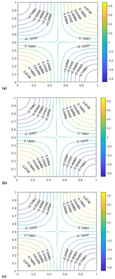
Figure 4.
Pressure contours of approximate solutions for three families: approximate NDL solution (a), approximate RT solution (b), approximate TH solution (c).
In this paragraph, using the data from the example provided in Section 5.1, we investigate the convergence of the discrete formulation for the three families of mixed elements under discussion.
Figure 5: For p, the degree of the pressure space is equal to 2 (a), (b), and (c), showing the velocity errors, the velocity errors, and the error of the pressure field, respectively. Similar to this, we examine the three mixed elements under discussion with degrees of p = 3 and p = 4. Figure 6 and Figure 7 demonstrate comparable results. The results were obtained with different consecutive mesh dimensions: 4 × 4; 8 × 8; 16 × 16; and 32 × 32.
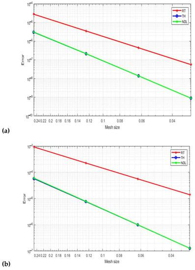
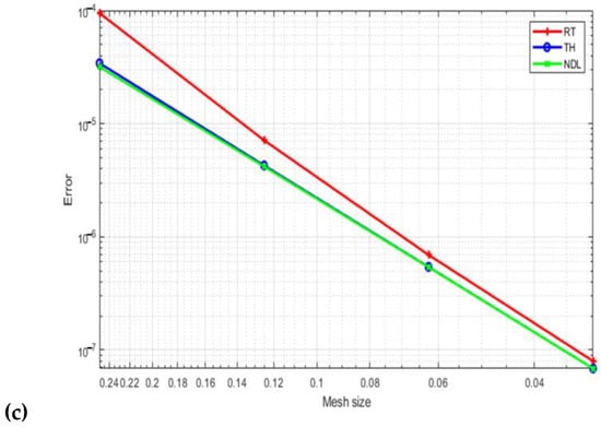
Figure 5.
Velocity field errors (a), velocity field errors (b), and the pressure field error (c) with p = 2.
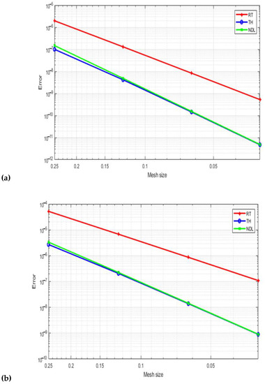
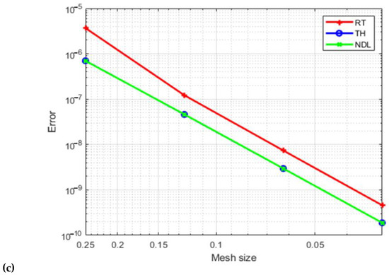
Figure 6.
Velocity field errors (a), velocity field errors (b), and the pressure field error (c) with p = 3.

Figure 7.
Velocity field errors (a), velocity field errors (b), and the pressure field error (c) with p = 4.
5.2. The Brinkman Problem on a NURBS Surface
Now that we have tested the approach on a parametric domain , we want to test it on a physical domain . Let the first quadrant be part of an annulus with inner radius r = 1 and outer radius R = 4 that is centered at the origin and is represented in polar coordinates by the inequalities and ; the domain is described in Figure 8.
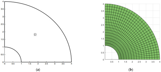
Figure 8.
Geometry of a quarter-ring (a), with the mesh of its NURBS represented as 16 × 32 (b).
In order to obtain a manufactured solution to systems (45) and (46), we consider a potential function such as:
where u is our exact velocity solution. It is easy to show that u satisfies the incompressibility condition div, . Using polar coordinates, here, we choose the potential function:
which gives, in Cartesian coordinates:
For the boundary condition, we assume that . The other problem data are defined as follows:
The constant . Figure 9 presents the dstribution of the permeability , with the pressure p chosen to have an average of zero on . Here, we use , and the right-hand side is calculated as . The vector fields and pressure contours, corresponding the IGA solutions to three types of element spaces, are presented in Figure 10 and Figure 11, with the domain discretized using a 16 × 32 mesh.
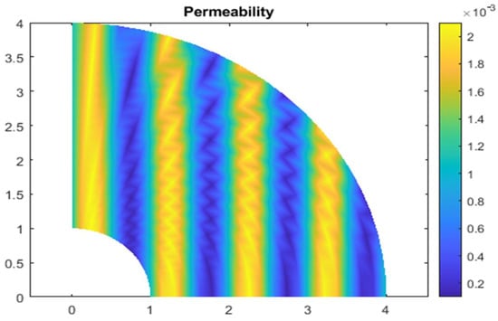
Figure 9.
Permeability.

Figure 10.
Vector fields of approximate solution for three families: NDL (a), approximate RT solution (b), approximate TH solution (c).

Figure 11.
Pressure contours of approximate solution for three families: NDL (a), approximate RT solution (b), approximate TH solution (c).
In this paragraph, using the data from the example provided in Section 5.1, we investigate the convergence of the discrete formulation for the three families of mixed elements under discussion.
Figure 12: For p, the degree of the pressure space is equal to 2 (a), (b), and (c), showing velocity -errors, velocity -errors, and the -errors in the pressure field, respectively. Similar to this, we examine the three mixed elements under discussion with degrees of p = 3 and p = 4. Figure 13 and Figure 14 demonstrate comparable results. Our results were obtained with different consecutive mesh dimensions: 4 × 8; 8 × 16; 16 × 32; and 32 × 64.
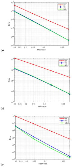
Figure 12.
Velocity field errors (a), velocity field errors (b), and the pressure field errors (c) for quarter of an annulus with p = 2.
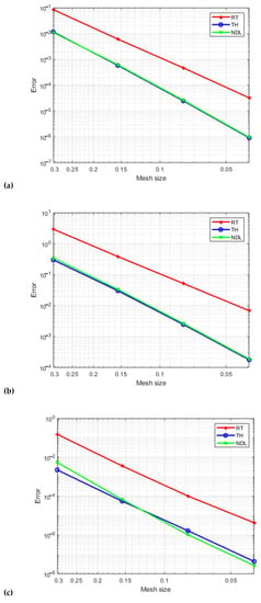
Figure 13.
Velocity field errors (a), velocity field errors (b), and the pressure field errors (c) for quarter of an annulus with p = 3.
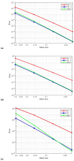
Figure 14.
Velocity field errors (a), velocity field errors (b), and the pressure field error (c) for quarter of an annulus with p = 4.
6. Conclusions
In this paper, we focus on the Brinkman system and investigate the performance of three well-established isogeometric discretizations that are known to be stable and converge toward the Stokes problem. These discretizations include an extension of the inf-sup stable Taylor–Hood element, as described in [1,3]; an extension of the Raviart–Thomas element, which is stable and preserves the structure by ensuring pointwise divergence-free discrete solutions, as described in [3]; and an extension of the inf-sup stable Nédélec element, as described in [2]. For two generic test cases corresponding to a domain of a square and a quarter ring, we evaluated the convergence behavior of the three families of elements in the case of mesh refinement for quadratic, cubic, and quartic approximations. An extension of the study described in this article will be presented in a future article on the multi-patch NURBS domain.
Author Contributions
Conceptualization, L.E.O., O.E.M., A.E.A. and A.E.; Methodology, A.E.A. and A.E.; Validation, L.E.O., O.E.M., A.E.A., S.V. and M.L.S.; Formal analysis, L.E.O., A.E.A., S.V. and M.L.S.; Investigation, L.E.O., O.E.M., A.E.A. and A.E.; Resources, A.E.; Data curation, L.E.O., O.E.M. and M.L.S.; Writing—original draft, L.E.O., O.E.M., A.E.A. and A.E.; Writing—review & editing, S.V. and M.L.S.; Visualization, L.E.O., O.E.M., A.E.A., A.E., S.V. and M.L.S.; Supervision, A.E.A., A.E., S.V. and M.L.S.; Funding acquisition, M.L.S. All authors have read and agreed to the published version of the manuscript.
Funding
This research received no external funding.
Data Availability Statement
The data associated with this research are available upon request.
Conflicts of Interest
The authors declare no conflict of interest.
References
- Buffa, A.; De Falco, C.; Sangalli, G. Isogeometric Analysis: Stable Elements for the 2D Stokes Equation. Int. J. Numer. Methods Fluids 2011, 65, 1407–1422. [Google Scholar]
- Bressan, A.; Sangalli, G. Isogeometric Discretizations of the Stokes Problem: Stability Analysis by the Macroelement Technique. IMA J. Numer. Anal. 2013, 33, 629–651. [Google Scholar] [CrossRef]
- Evans, J.A.; Hughes, T.J.R. Isogeometric Divergence-Conforming b-Splines for the Darcy–Stokes–Brinkman Equations. Math. Model. Methods Appl. Sci. 2013, 23, 671–741. [Google Scholar] [CrossRef]
- Hughes, T.J.; Cottrell, J.A.; Bazilevs, Y. Isogeometric Analysis: CAD, Finite Elements, NURBS, Exact Geometry and Mesh Refinement. Comput. Methods Appl. Mech. Eng. 2005, 194, 4135–4195. [Google Scholar]
- Cottrell, J.A.; Hughes, T.J.; Bazilevs, Y. Isogeometric Analysis: Toward Integration of CAD and FEA; John Wiley & Sons: Hoboken, NJ, USA, 2009. [Google Scholar]
- De Boor, C.; De Boor, C. A Practical Guide to Splines; Springer-Verlag: New York, NY, USA, 1978; Volume 27. [Google Scholar]
- El Fakkoussi, S.; Moustabchir, H.; Elkhalfi, A.; Pruncu, C.I. Computation of the Stress Intensity Factor KI for External Longitudinal Semi-Elliptic Cracks in the Pipelines by FEM and XFEM Methods. Int. J. Interact. Des. Manuf. 2019, 13, 545–555. [Google Scholar]
- Łoś, M.M.; Woźniak, M.; Paszyński, M.; Lenharth, A.; Hassaan, M.A.; Pingali, K. IGA-ADS: Isogeometric Analysis FEM Using ADS Solver. Comput. Phys. Commun. 2017, 217, 99–116. [Google Scholar] [CrossRef]
- Piegl, L.; Tiller, W. The NURBS Book; Springer Science & Business Media: Berlin/Heidelberg, Germany, 1996. [Google Scholar]
- Yakoubi, K.; Montassir, S.; Moustabchir, H.; Elkhalfi, A.; Pruncu, C.I.; Arbaoui, J.; Farooq, M.U. An Extended Finite Element Method (XFEM) Study on the Elastic T-Stress Evaluations for a Notch in a Pipe Steel Exposed to Internal Pressure. Mathematics 2021, 9, 507. [Google Scholar] [CrossRef]
- Babuška, I. The Finite Element Method with Lagrangian Multipliers. Numer. Math. 1973, 20, 179–192. [Google Scholar]
- Brezzi, F. On the Existence, Uniqueness and Approximation of Saddle-Point Problems Arising from Lagrangian Multipliers. In Publications Mathématiques et Informatique de Rennes; Université de Rennes: Rennes, France, 1974; pp. 1–26. [Google Scholar]
- El Moutea, O.; El Amri, H.; El Akkad, A. Finite Element Method for the Stokes–Darcy Problem with a New Boundary Condition. Numer. Anal. Appl. 2020, 13, 136–151. [Google Scholar]
- El-Mekkaoui, J.; Elkhalfi, A.; Elakkad, A. Resolution of Stokes Equations with the Ca, b Boundary Condition Using Mixed Finite Element Method. WSEAS Trans. Math. 2013, 12, 586–597. [Google Scholar]
- Elakkad, A.; Elkhalfi, A.; Guessous, N. An a Posteriori Error Estimate for Mixed Finite Element Approximations of the Navier-Stokes Equations. J. Korean Math. Soc. 2011, 48, 529–550. [Google Scholar]
- Mardal, K.A.; Tai, X.-C.; Winther, R. A Robust Finite Element Method for Darcy–Stokes Flow. SIAM J. Numer. Anal. 2002, 40, 1605–1631. [Google Scholar]
- Araya, R.; Harder, C.; Poza, A.H.; Valentin, F. Multiscale Hybrid-Mixed Method for the Stokes and Brinkman Equations—The Method. Comput. Methods Appl. Mech. Eng. 2017, 324, 29–53. [Google Scholar] [CrossRef]
- Bernardi, C.; Hecht, F.; Nouri, F.Z. A New Finite-Element Discretization of the Stokes Problem Coupled with the Darcy Equations. IMA J. Numer. Anal. 2010, 30, 61–93. [Google Scholar] [CrossRef]
- Botti, L.; Di Pietro, D.A.; Droniou, J. A Hybrid High-Order Discretisation of the Brinkman Problem Robust in the Darcy and Stokes Limits. Comput. Methods Appl. Mech. Eng. 2018, 341, 278–310. [Google Scholar] [CrossRef]
- Juntunen, M.; Stenberg, R. Analysis of Finite Element Methods for the Brinkman Problem. Calcolo 2010, 47, 129–147. [Google Scholar]
- Burman, E.; Hansbo, P. A Unified Stabilized Method for Stokes’ and Darcy’s Equations. J. Comput. Appl. Math. 2007, 198, 35–51. [Google Scholar] [CrossRef]
- Cáceres, E.; Gatica, G.N.; Sequeira, F.A. A Mixed Virtual Element Method for the Brinkman Problem. Math. Model. Methods Appl. Sci. 2017, 27, 707–743. [Google Scholar] [CrossRef]
- Di Pietro, D.A.; Droniou, J. A Polytopal Method for the Brinkman Problem Robust in All Regimes. Comput. Methods Appl. Mech. Eng. 2023, 409, 115981. [Google Scholar] [CrossRef]
- Könnö, J.; Stenberg, R. H(Div)-Conforming Finite Elements for the Brinkman Problem. Math. Model. Methods Appl. Sci. 2011, 21, 2227–2248. [Google Scholar] [CrossRef]
- Vacca, G. An H1-Conforming Virtual Element for Darcy and Brinkman Equations. Math. Model. Methods Appl. Sci. 2018, 28, 159–194. [Google Scholar] [CrossRef]
- Zhang, L.; Feng, M.; Zhang, J. A Globally Divergence-Free Weak Galerkin Method for Brinkman Equations. Appl. Numer. Math. 2019, 137, 213–229. [Google Scholar] [CrossRef]
- El Moutea, O.; El Amri, H.; El Akkad, A. Mixed Finite Element Method for Flow of Fluid in Complex Porous Media with a New Boundary Condition. Comput. Sci. 2020, 15, 413–431. [Google Scholar]
- Anaya, V.; Gatica, G.N.; Mora, D.; Ruiz-Baier, R. An Augmented Velocity–Vorticity–Pressure Formulation for the Brinkman Equations. Int. J. Numer. Methods Fluids 2015, 79, 109–137. [Google Scholar]
- Bressan, A. Isogeometric Regular Discretization for the Stokes Problem. IMA J. Numer. Anal. 2011, 31, 1334–1356. [Google Scholar] [CrossRef]
- Buffa, A.; Rivas, J.; Sangalli, G.; Vázquez, R. Isogeometric Discrete Differential Forms in Three Dimensions. SIAM J. Numer. Anal. 2011, 49, 818–844. [Google Scholar] [CrossRef]
- Hoang, T.; Verhoosel, C.V.; Auricchio, F.; van Brummelen, E.H.; Reali, A. Mixed Isogeometric Finite Cell Methods for the Stokes Problem. Comput. Methods Appl. Mech. Eng. 2017, 316, 400–423. [Google Scholar] [CrossRef]
- Bazilevs, Y.; Beirao da Veiga, L.; Cottrell, J.A.; Hughes, T.J.; Sangalli, G. Isogeometric Analysis: Approximation, Stability and Error Estimates for h-Refined Meshes. Math. Model. Methods Appl. Sci. 2006, 16, 1031–1090. [Google Scholar]
- Hosseini, B.S.; Turek, S.; Möller, M.; Palmes, C. Isogeometric Analysis of the Navier–Stokes–Cahn–Hilliard Equations with Application to Incompressible Two-Phase Flows. J. Comput. Phys. 2017, 348, 171–194. [Google Scholar] [CrossRef]
- Nielsen, P.N.; Gersborg, A.R.; Gravesen, J.; Pedersen, N.L. Discretizations in Isogeometric Analysis of Navier–Stokes Flow. Comput. Methods Appl. Mech. Eng. 2011, 200, 3242–3253. [Google Scholar] [CrossRef]
- Aronson, R.M.; Evans, J.A. Divergence-Conforming Isogeometric Collocation Methods for the Incompressible Navier–Stokes Equations. Comput. Methods Appl. Mech. Eng. 2023, 410, 115990. [Google Scholar] [CrossRef]
- Evans, J.A.; Hughes, T.J.R. Isogeometric Divergence-Conforming B-Splines for the Unsteady Navier–Stokes Equations. J. Comput. Phys. 2013, 241, 141–167. [Google Scholar] [CrossRef]
- Hosseini, B.S.; Möller, M.; Turek, S. Isogeometric Analysis of the Navier–Stokes Equations with Taylor–Hood B-Spline Elements. Appl. Math. Comput. 2015, 267, 264–281. [Google Scholar] [CrossRef]
- Rogers, D.F. An Introduction to NURBS: With Historical Perspective; Morgan Kaufmann: Burlington, MA, USA, 2001. [Google Scholar]
- Bosy, M.; Montardini, M.; Sangalli, G.; Tani, M. A Domain Decomposition Method for Isogeometric Multi-Patch Problems with Inexact Local Solvers. Comput. Math. Appl. 2020, 80, 2604–2621. [Google Scholar] [CrossRef]
- Chan, C.L.; Anitescu, C.; Rabczuk, T. Isogeometric Analysis with Strong Multipatch C1-Coupling. Comput. Aided Geom. Des. 2018, 62, 294–310. [Google Scholar] [CrossRef]
- Tahaei Yaghoubi, S.; Balobanov, V.; Mousavi, S.M.; Niiranen, J. Variational Formulations and Isogeometric Analysis for the Dynamics of Anisotropic Gradient-Elastic Euler-Bernoulli and Shear-Deformable Beams. Eur. J. Mech.-A/Solids 2018, 69, 113–123. [Google Scholar] [CrossRef]
- Da Veiga, L.B.; Buffa, A.; Sangalli, G.; Vázquez, R. Mathematical Analysis of Variational Isogeometric Methods. Acta Numer. 2014, 23, 157–287. [Google Scholar]
- Vázquez, R. A New Design for the Implementation of Isogeometric Analysis in Octave and Matlab: GeoPDEs 3.0. Comput. Math. Appl. 2016, 72, 523–554. [Google Scholar] [CrossRef]
Disclaimer/Publisher’s Note: The statements, opinions and data contained in all publications are solely those of the individual author(s) and contributor(s) and not of MDPI and/or the editor(s). MDPI and/or the editor(s) disclaim responsibility for any injury to people or property resulting from any ideas, methods, instructions or products referred to in the content. |
© 2023 by the authors. Licensee MDPI, Basel, Switzerland. This article is an open access article distributed under the terms and conditions of the Creative Commons Attribution (CC BY) license (https://creativecommons.org/licenses/by/4.0/).