Article

Influences of Boundary Temperature and Angular Velocity on Thermo-Elastic Characteristics of a Functionally Graded Circular Disk Subjected to Contact Forces

Department of Electrical Engineering, Dong-A University, 37, Nakdong-daero 550beon-gil, Saha, Busan 49315, Korea
Mathematics 2022, 10(9), 1518; https://doi.org/10.3390/math10091518
Submission received: 24 March 2022 / Revised: 20 April 2022 / Accepted: 29 April 2022 / Published: 2 May 2022

Abstract

:
The behaviors of functionally graded (FG) engineering structures are influenced by various parameters, such as the boundary temperature, the angular velocity, variations in the thickness, the weight of the structure, and the loading state. The thermo-elastic characteristics of FG rotating circular disks under the loading of contact forces were investigated. Hooke’s law in plane stress problems was applied to derive a pair of partial differential equations and a finite volume method was developed due to the complexity of the governing equations. The thermo-elastic characteristics of the FG rotating disks were investigated according to the variations in their outer boundary temperature and angular velocity. The increase in the outer boundary temperature caused crack generation at the inner surface of the circular disk and on the opposite side to the loading point. The increase in the angular velocity caused unstable thermo-elastic behaviors near the area of the outer boundary surface, especially at 0.7 < ( r a ) / ( b a )   < 0.9, and may have led to crack generation at the outer surface of the rotating disk. These results may be applied to the design of functionally graded circular cutters or grinding disks undergoing contact forces to produce proper and reliable thermo-elastic characteristics for practical applications.

1. Introduction

Due to the emerging need for new materials to provide strong, stiff, and lightweight structural components, research on composite materials (CMs) and functionally graded materials (FGMs) is actively underway. CMs are made of two or more different materials; FGMs are peculiar compositions of CMs and are usually made from two constituents with continuous variations in their physical and mechanical properties in one or more directions. CMs are exposed to significant problems, such as delamination and crack propagation, because of their different thermal and mechanical properties, while the continuity variation in FGMs reduces stress concentration and optimizes stress distribution. Nevertheless, FGMs display good performance in high-temperature environments, especially under severe temperatures. Owing to these, FGMs are widely used in space vehicles, nuclear power plants, aircraft, and many other engineering applications.
Rotating circular disks are extensively used in many engineering components, such as grinders, turbines, gears, flywheels, centrifugal compressors, circular saws, propellers, and internal combustion engines. Dai and Dai [1] adopted an angular acceleration parameter in a FG rotating circular disk under a loading of changing temperature field to resolve the displacement and stress distributions. Using an infinitesimal theory combining plane elasticity and the complementary functions method, Yildirim [2] presented hydrogen-induced stresses in FG axisymmetric spheres, cylinders, and disks. They verified that the variation in the grading rules is more sensitive to radial stress than to hoop stress. A higher-order finite beam element and the Lord–Shulman theory were utilized by Entezari et al. [3] to analyze the thermomechanical properties of FG rotating disks. Pal and Das [4] used a mathematical model approach to investigate the free vibration behavior of a FG rotating annular micro-disk based on the potential energy and Hamilton’s principle. Royal et al. [5] employed a variation formulation method involving the radial displacement field as the unknown variable for the investigation of uniform-thickness FG rotating disk behavior, and Arani et al. [6] performed an analysis of magneto-thermo-elastic stresses and thermo-piezo-magneto-mechanical stresses in rotating FGM disks. Variable thickness is an indispensable parameter in the stability performance of FG circular disks. Eraslan et al. [7] presented analytical solutions for the elastic plastic stress distribution in annular rotating disks with variable thickness profiles. The deformation and stresses of FG orthotropic non-uniform rotating disks with material properties varying along the radial and tangential directions were investigated by Sondhi et al. [8] using a finite element method, and they validated a significant reduction in stresses in variable-thickness in comparison with uniform disks. A FG rotating disk subjected to both mechanical and thermal stresses was considered by Bayat et al. [9] to analyze the deformation and stresses, testifying to the superior stability in the stresses and the displacement distribution profiles. Yildirim and Tutuncu [10] performed an instability analysis of FGM rotating disks with variable thickness. Variable material property theory was applied by Mahdavi et al. [11] to present an analysis of the thermo-mechanical behavior of FG rotating discs with variable thickness, showing that discs with variable thickness profiles have smaller stresses than those with constant thickness. Kadkhodayan and Golmakani [12] carried out a non-linear analysis of FG solid and hollow radiating axisymmetric disks with uniform and variable thickness undergoing bending load. First-order shear deformation theory and the large-deflection von Karman equation were adopted for the derivation of the governing equation. The weight of the engineering structures is a crucial parameter in the determination of thermal and mechanical properties. Khorsand and Tang [13] determined the optimized weight of a FG hollow disk with variable density in the radial direction under the action of thermal-mechanical loads using an algorithm with coupled co-evolutionary particle swarm optimization and the differential quadrature method. Zeinkiewics and Campbell [14] used the combination of a boundary element method and sequential linear programming to accomplish the curve optimization of engineering structures with the purpose of reducing stress in the whole body. A combination of simulated annealing, PSO, and the Karush–Kuhn–Tucker method was applied by Jafari et al. [15] to obtain the optimized weights of rotating disks.
Recently, various methods to analyze the elastic and thermal-elastic characteristics of FG circular-shape structures have been explored by many authors. Saini et al. [16] used Kirchhoff’s plate theory and Eringen’s nonlocal elasticity theory to determine the behavior of non-uniform FG asymmetric circular and annular nanodiscs in the thermal buckling state. The power-law model was adopted to describe the temperature-independent effective mechanical properties of FGMs. Timoshen beam theory and a finite element method were applied by Gayen et al. [17] to study the stability behavior of a FG shaft rotor-disk system considering various parameters, such as the rigid end bearing conditions, cracks, and internal damping. Al-Furjan et al. [18] utilized three-dimensional refined higher-order shear deformation theory and Hamilton’s principle, considering various sets of boundary conditions, in the investigation of a non-polynomial framework for the bending responses of FG graphene nanoplatelet composite reinforced disks. Sathujoda [19] presented a corrosion detection method for the analysis of a FG rotor system describing the spatial variation in a wavelet transform to modify the computed FG rotor-mode shapes into the wavelet domain, in order to identify and locate the local corrosion defect. The successive approximation method was applied by Saeedi et al. [20] to present the thermo-elasto-plastic behavior of a thick-walled cylindrical shell made of FGM. The numerical solutions were obtained using the differential quadrature method, involving the combination of the internal pressure on and the temperature gradient of the shell. Moreover, theoretical research on thermo-elastic problems is underway. Liu et al. [21] employed the Tychonoff fixed-point theorem for multivalued operators to prove the existence of a solution for the thermo-elastic contact problem considering the nonlinear thermo-elastic constitutive law. The heat-exchange boundary condition on the contact surface is expressed with the function of the normal displacement and determined by the difference in the temperature of the body. Chawda and Bhandakkar [22] proposed a semi-analytical technique for the solution of the mixed boundary value problem in a FG circular annulus under the action of a radially varying shear modulus. The Fourier series and Airy stress functions approaches were used to investigate the elastic characteristics. Howell et al. [23] and Paoli and Shillor [24] utilized Barber’s heat exchange condition to represent the thermal interaction upon contact between a thermos-elastic body and a rigid thermally active foundation, in the absence of wear. Paoli and Shillor used the Galerkin method to show the existence of a weak solution and Howell et al. described two classes of dynamic thermo-elastic problem. Cao-Rial et al. [25] explored the contact and the constitutive law governed by a normal damped response function and the Duhamel–Neumann relation, respectively, to show the existence and uniqueness of a solution to the dynamic thermo-elastic contact problem.
However, most of studies concerning the thermo-elastic contact problem are limited to the boundary conditions caused by the temperature of the body. The contact forces generated in-use between two different elastic structures are unrecognized and the investigation into the thermal-mechanical behaviors of rotating FGM circular disks undergoing various contact loads are not studied in depth in the literature, even though loads are crucial parameters in the determination of thermo-elastic characteristics. We considered the inner-outer boundary temperatures, angular velocity, and forces created due to the contact during operation as contact loading parameters when conducting our research. Nevertheless, a finite volume method was introduced for the detailed investigation of the elastic and thermo-elastic characteristics over the sequentially changing circular domain. In this study, the thermo-elastic characteristics of a rotating Al 2 O 3 / Al FGM disk under the action of contact force loads are presented. The Young’s modulus, CTE, and density of the FGM circular disks were assumed to vary exponentially only in the radial direction due to symmetry with respect to the axis of the disk for a constant Poisson’s ratio. Hooke’s law was applied, considering the contact forces, to obtain a pair of partial differential equations, and a finite volume method was adopted for the numerical approaches due to the complexity of the governing equation.

2. Materials and Methods

A rotating FGM circular disk subjected to contact forces was studied (see Figure 1). The disk featured a concentric circular hole, and the origin of the polar coordinate system r θ was assumed to be located at the center of the disk and hole. As shown in Figure 1, constituent materials, of dark and white colors, of FGM circular disk were designated by A and B, and the distribution of each material varied continuously along the radial direction only. The radii of the hole and outer surface of the disk were designated as a and b. Due to the assumption of only radial variation in material distributions, the FGM disk can be reduced to an axisymmetric problem and all properties relating the present circular disk problem can be treated as functions of r only. Thus, the Young’s modulus, the coefficient of the thermal expansion, and the density of the disk are assumed to vary exponentially as:
E = E 0 e β r ,
α = α 0 e ϑ r ,
ρ = ρ 0 e μ r .
Since the disk is composed of 100% material A at the surface of the hole (r = a) and 100% material B at the outer surface (r = b), the constants in Equations (1)–(3) can be determined as follows:
E 0 = E A e β a ,
α 0 = α A e ϑ a ,
ρ 0 = ρ A e μ a ,
β = 1 a b l n ( E A E B ) ,
ϑ = 1 a b l n ( α A α B ) ,
μ = 1 a b l n ( ρ A ρ B ) .
The subscripts A and B denote the properties of the constituent materials A and B, respectively. However, the non-subscripted variables were used to denote the properties of FGM composed of the materials A and B.

2.1. Mathematical Formulation

Let T ( r ) be the function of temperature variation at any distance r . Next, based on Hooke’s law in plane stress problems [26], the strain–stress relations undergoing thermal expansion are written as
ε r = 1 E [ σ r υ σ θ ] + α T ,   ε θ = 1 E [ σ θ υ σ r ] + α T , τ r θ = E 2 ( 1 + ν ) γ r θ ,   τ θ z = 0 ,   τ r z = 0 .
in polar coordinates. The strain-displacement components are given by
ε r = u r ,   ε θ = 1 r v θ + u r ,   ε z = 0 , γ r θ = 1 r u θ + v r v r ,   γ z θ = 0 ,   γ r z = 0 .
Now, equilibrium equations in polar coordinates are
σ r r + 1 r τ r θ θ + σ r σ θ r + ρ ω 2 r = 0 , σ θ θ + r τ r θ r + 2 τ r θ = 0 .
The governing equations are, through the combination of Equations (10)–(12),
u r ( r u r ) + 1 υ 2 r 2 u θ 2 3 υ 2 r v θ + 1 + υ 2 2 v r θ u r + 1 υ 2 E ρ ω 2 r 2 = ( υ + 1 ) α r d T ( r ) d r , 1 υ 2 r ( r v r ) + 1 r 2 v θ 2 3 υ 2 r u θ + 1 + υ 2 2 u r θ 1 υ 2 v r = 0 .

2.2. Temperature Distribution Profiles

We assume that the disk is subjected to the loading of symmetric temperature in the radial direction only. Consequently, the differential equation for the temperature distribution in the polar coordinate is
1 r r ( r T r ) = 0 .
The general solution of Equation (14) takes the form of
T ( r ) = c 1   l n r + c 2 ,
where c 1 and c 2 are integral constants. The following boundary conditions
σ r ( a ,   θ ) = 0 ,   σ r ( b ,   θ { 0 } ) = 0 ,   σ r ( b ,   0 ) = P   at   contact   point ,
are used to investigate the thermo-elastic characteristics of a present rotating circular disk subjected to contacting forces.

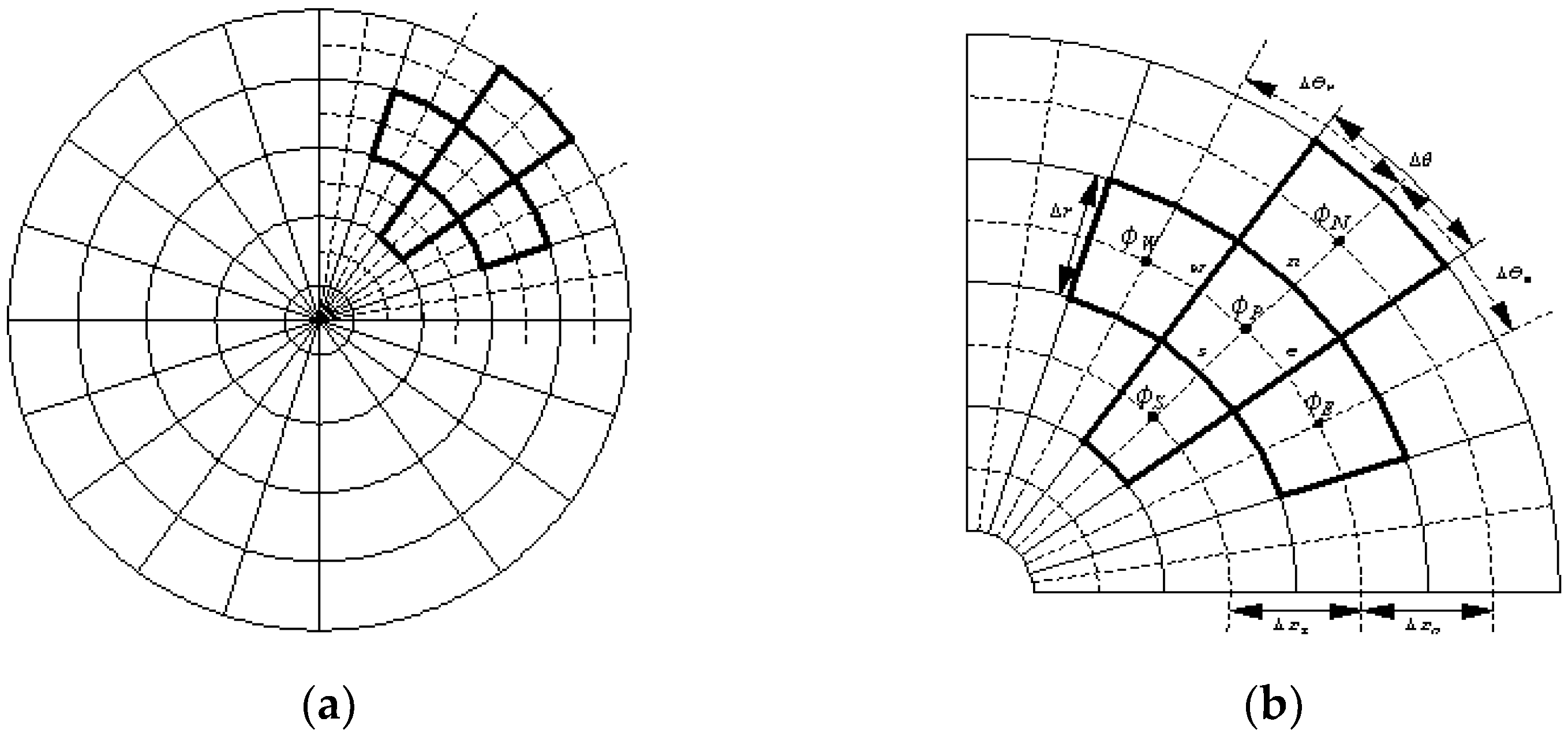
2.3. Finite Volume Formulation

Since a pair of governing equations is too complicated to solve analytically, a numerical technique is required for the approximation. To this end, a finite volume method for approximated solutions is used; the domain is divided up into control volumes and integrates the field equations over each control volume (see Figure 2).
The finite surface mesh is denoted by ( i , j ) and the discretization for the governing equations is developed based on the following relations at the adjacent locations.
( w r ) i , j + 1 2 = w i , j + 1 w i , j Δ r ,   ( w r ) i , j 1 2 = w i , j w i , j 1 Δ r ,   ( w r ) i , j 1 = w i , j + 1 w i , j 1 2 Δ r , ( w θ ) i + 1 2 , j = w i + 1 , j w i , j Δ r ,   ( w θ ) i 1 2 , j = w i , j w i 1 , j Δ r ,   ( w θ ) i , j 1 = w i + 1 , j w i 1 , j 2 Δ θ , w m + 1 2 , j + 1 = w m , j + 1 + 1 4 ( 3 w m , j + 1 4 w m 1 , j + 1 + w m 2 , j + 1 ) , w m 1 2 , j + 1 = w m 1 , j + 1 + 1 4 ( w m , j + 1 w m 2 , j + 1 ) ,   w i + 1 2 , j + 1 2 = 1 2 ( w i + 1 2 , j + 1 + w i + 1 2 , j ) .
The subscript 1 2 implies the value of the displacement at the boundary of the control surface (see Figure 2b). Based on the above relations at the adjacent locations, the governing equations are discretized through the following processes:
C V r ( r u r ) d V = [ ( r u r ) n ( r u r ) s ] d θ = Δ θ [ r i , j + 1 2 ( u r ) i , j + 1 2 r i , j 1 2 ( u r ) i , j 1 2 ]
= Δ θ { r i , j + 1 2 [ u i , j + 1 u i , j Δ r ] r i , j 1 2 [ u i , j u i , j 1 Δ r ] } ,
C V 1 ν 2 r θ ( u θ ) d V = [ 1 ν 2 r w ( u θ ) w 1 ν 2 r e ( u θ ) e ] d r = Δ r [ 1 ν 2 r i , j ( u θ ) i + 1 2 , j 1 ν 2 r i , j ( u θ ) i 1 2 , j ]
= 1 ν 2 r i , j Δ r { [ u i + 1 , j u i , j Δ θ ] [ u i , j u i 1 , j Δ θ ] } ,
C V 3 ν 2 r v θ d V = Δ r [ 3 ν 2 r w v w 3 ν 2 r e Δ r e v e ] = Δ r 3 ν 2 r i , j [ v i + 1 2 , j v i 1 2 , j ]
                      = Δ r 3 ν 2 r i , j [ ( v i , j + 1 4 ( 3 v i , j 4 v i 1 , j + v i 2 , j ) ) ( v i 1 , j + 1 4 ( v i , j v i 2 , j ) ) ] ,
C V 1 + ν 2 r ( v θ ) d V = 1 + ν 2 Δ r Δ θ [ ( v θ ) n ( v θ ) s Δ r ] = 1 + ν 2 Δ θ [ ( v θ ) i , j + 1 2 ( v θ ) i , j 1 2 ]
= 1 + ν 2 Δ θ [ v i + 1 2 , j + 1   2 v i 1 2 , j + 1 2 Δ θ v i + 1 2 , j 1   2 v i 1 2 , j 1 2 Δ θ ] ,
= 1 + ν 2 [ 1 2 ( v i + 1 2 , , j + 1 + v i + 1 2 , j ) 1 2 ( v i + 1 2 , j + v i + 1 2 , j 1 ) 1 2 ( v i 1 2 , j + 1 + v i 1 2 , j ) + 1 2 ( v i 1 2 , j + v i 1 2 , j 1 ) ]
= 1 + ν 4 [ v i + 1 2 , j + 1 v i + 1 2 , j 1 v i 1 2 , j + 1 + v i 1 2 , j 1 ]
= 1 + ν 4 [ ( v i , j + 1 + 1 4 ( 3 v i , j + 1 4 v i 1 , j + 1 + v i 2 , j + 1 ) ) ( v i , j 1 + 1 4 ( 3 v i , j 1 4 v i 1 , j 1 + v i 2 , j 1 ) )
( v i 1 , j + 1 + 1 4 ( v i , j + 1 v i 2 , j + 1 ) ) + ( v i 1 , j 1 + 1 4 ( v i 1 , j 1 v i 2 , j 1 ) ) ] ,
C V ( u r + 1 ν 2 E ρ ω 2 r 2 ) d V = Δ r Δ θ ( u P r P + 1 ν 2 E ρ ω 2 r P 2 )
= Δ r Δ θ ( u i , j r i , i + 1 ν 2 E ρ ω 2 r i , j 2 ) ,
C V ( ν + 1 ) α r d T d r d V = ( ν + 1 ) α r P Δ θ [ T n T s ] = ( ν + 1 ) α r i , j Δ θ [ T i , j + 1 2 T i , j 1 2 ] ,
C V 1 ν 2 r ( r v r ) d V = 1 ν 2 Δ θ [ r n v N v P Δ r r s v p v s Δ r ]
                                                                                                                                                = 1 ν 2 Δ θ Δ r [ r i , j + 1 2 ( v i , j + 1 v i , j ) r i , j 1 2 ( v i , j v i , j 1 ) ] ,
C V 1 r θ ( v θ ) d V = Δ r Δ θ 1 r i , j [ v i + 1 , j 2 v i , j + v i 1 , j ] ,
C V 3 ν 2 r u θ d V = 3 ν 2 1 r i , j [ ( u i , j + 1 4 ( 3 u i , j 4 u i 1 , j + u i 2 , j ) ) ( u i 1 , j + 1 4 ( u i , j u i 2 , j ) ) ] ,
C V 1 + ν 2 r ( u θ ) d V = = 1 + ν 4 [ ( u i , j + 1 + 1 4 ( 3 u i , j + 1 4 u i 1 , j + 1 + u i 2 , j + 1 ) )
( u i , j 1 + 1 4 ( 3 u i , j 1 4 u i 1 , j 1 + u i 2 , j 1 ) ) ( u i 1 , j + 1 + 1 4 ( u i , j + 1 u i 2 , j + 1 ) )
+ ( u i 1 , j 1 + 1 4 ( u i 1 , j 1 u i 2 , j 1 ) ) ] ,
C V 1 ν 2 v r d V = Δ r Δ θ 1 ν 2 v P r P = Δ r Δ θ 1 ν 2 1 r i , j v i , j
The discretized linear systems of the governing equations are
A 11 u i + 1 , j + A 12 u i , j + 1 + A 13 u i , j + A 14 u i , j 1 + A 15 u i 1 , j + B 11 v i , j + 1 + B 12 v i , j + B 13 v i , j 1
+ B 14 v i 1 , j + 1 + B 15 v i 1 , j + B 16 v i 1 , j 1 + B 17 v i 2 , j + 1 + B 18 v i 2 , j + B 19 v i 2 , j 1 = f i , j ,
A 21 u i , j + 1 + A 22 u i , j + A 23 u i , j 1 + A 24 u i 1 , j + 1 + A 25 u i 1 , j + A 26 u i 1 , j 1 + A 27 u i 2 , j + 1
+ A 28 u i 2 , j + A 29 u i 2 , j 1 + B 21 v i + 1 , j + B 22 v i , j + 1 + B 23 v i , j + B 24 v i , j 1 + B 25 v i 1 , j = 0 ,
where
A 11 = 1 ν 2 Δ r Δ θ 1 r i , j ,   A 12 = Δ θ Δ r r i , j + 1 2 ,   A 13 = Δ θ Δ r ( r i , j + 1 2 + r i , j 1 2 ) [ ( 1 υ ) Δ r Δ θ + Δ r Δ θ ] 1 r i , j ,
A 14 = Δ θ Δ r r i , j 1 2 ,   A 15 = 1 ν 2 Δ r Δ θ 1 r i , j ,   B 11 = 3 8 ( 1 + υ ) ,   B 12 = 3 4 ( 3 υ ) Δ r 1 r i , j ,
B 13 = 7 16 ( 1 + υ ) ,   B 14 = 1 2 ( 1 + υ ) ,   B 15 = 5 2 ( 3 υ ) 1 r i , j ,   B 16 = 9 16 ( 1 + υ ) ,
B 17 = 1 8 ( 1 + υ ) ,   B 18 = 3 4 ( 3 υ ) Δ r 1 r i , j ,   B 19 = 1 8 ( 1 + υ ) ,
f i , j = ( 1 + υ ) α r i , j Δ θ ( T i , j + 1 2 T i , j 1 2 ) Δ r Δ θ ρ ω 2 1 υ 2 E r i , j 2
A 21 = 3 8 ( 1 + υ ) ,   A 22 = 3 4 ( 3 υ ) Δ r 1 r i , j ,   A 23 = 7 16 ( 1 + υ ) ,   A 24 = 1 2 ( 1 + υ ) ,
A 25 = ( 3 υ ) Δ r 1 r i , j ,   A 26 = 9 16 ( 1 + υ ) ,   A 27 = 1 8 ( 1 + υ ) ,   A 28 = ( 3 υ ) Δ r 1 r i , j ,
A 29 = 1 8 ( 1 + υ ) ,   B 21 = Δ r Δ θ 1 r i , j ,   B 22 = Δ θ Δ r r i , j + 1 2 ,
                        B 23 = Δ θ Δ r ( r i , j + 1 2 + r i , j 1 2 ) 1 υ 2 Δ r Δ θ 1 r i , j 2 Δ r Δ θ 1 r i , j ,   B 24 = Δ θ Δ r r i , j 1 2 ,   B 25 = Δ r Δ θ 1 r i , j .

2.4. Validation of Numerical Approach

For the validation of the finite volume method, Laplace equation
r ( r r ) + 1 r 2 θ 2 = 0 ,   1 r R
with completementary conditions of (i) boundary condition: ( R , θ ) = V 0 , (ii) symmetry about the x-axis: ( θ ) = ( 2 π θ ) is considered. Note that the analytical solution of Equation (17) satisfying the completementary conditions is
( r , θ ) = V 0 + ( R 2 r r ) cos θ .
The discretized form of Laplace equation is depicted through the following process:
C V r ( r r ) d V = [ ( r r ) n ( r r ) s ] d θ = r n Δ θ n ( r ) n r s Δ θ s ( r ) s
= r n Δ θ n [ N P δ r P N ] r s Δ θ s [ P S δ r S P ]
= r n Δ θ n δ r P N N + r s Δ θ s δ r S P S ( r n Δ θ n δ r P N + r s Δ θ s δ r S P ) P ,
C V 1 r θ ( θ ) d V = 1 r w Δ r w ( θ ) w 1 r e Δ r e ( θ ) e
= 1 r w Δ r w δ θ W P W + 1 r e Δ r e δ θ P E E ( 1 r e Δ r e δ θ P E + 1 r w Δ r w δ θ W P ) P ,
a p p = a N N + a S s + a E E + a W W ,
a N = r n Δ θ n δ r P N ,         a S = r s Δ θ s δ r S P ,         a E = 1 r e Δ r e δ θ P E ,   a W = 1 r w Δ r w δ θ W P ,
a P = r n Δ θ n δ r P N + r s Δ θ s δ r S P + 1 r e Δ r e δ θ P E + 1 r w Δ r w δ θ W P .
Under the chosen conditions of
δ r N S = 2 Δ r ,   δ r P N = δ r S P = Δ r ,   δ θ E W = 2 Δ θ ,   δ θ P W = δ θ P E = Δ θ ,
the validation of the finite volume method was processed, and the result is described in Figure 3. The numerical solution was almost identical to the analytical solution, which shows the stability of the finite volume approach.

3. Numerical Results and Discussion

The differential equation introduced in Section 2.1 was applied to obtain the temperature distribution profile. The symbols T a and T b represent the temperature degrees of the inner and outer boundaries, respectively, and the values of T a and T b are used to determine the integral constants. The finite volume formula derived in Section 2.3 was employed to search for the approximated solutions of the different components of displacement, stress, and strain for an A l 2 O 3 /   A l FGM circular disk. Table 1 shows the mechanical and thermal properties of these ingredient materials.
The influence of the outer surface temperature on the thermo-elastic characteristics is exhibited in Figure 4, Figure 5 and Figure 6. Figure 4 explains the displacement distributions. At the contact point θ = 0 , the radial displacement of the circular disk developed in the direction of the concentric hole until around ( r a ) / ( b a ) = 0.9 , and an abrupt rise occurred in the opposite direction after ( r a ) / ( b a ) = 0.9 (see Figure 4a). The magnitude of the radial displacement increased with the rise in the outer surface temperature, and the largest displacement occurred at the contact point. However, a different phase in the radial distribution appeared at θ = 180 . As shown in Figure 4b, greater radial displacement was produced in the direction of the concentric hole in terms of magnitude, and the largest radial displacement occurred around ( r a ) / ( b a ) = 0.3 , with T b = 600 . The circumferential displacement presented the normalized radius values of ( r a ) / ( b a ) = 0.1 and 0.9. Near the inner surface of the circular disk, the circumferential displacement was sensitive to the variation in the outer surface temperature and developed in the negative direction (see Figure 4c). A larger circumferential displacement appeared along with the increase in the outer surface temperature, and the largest circumferential displacement occurred around θ = 0.5 radian of T b = 600 . As shown in Figure 4d, the circumferential displacement experienced dramatic change in both positive and negative directions near the outer boundary of the circular disk. The influence of the outer surface temperature variation on the circumferential displacement was minor at θ = 0 , and the effects of the temperature variation appeared after θ = 1 radian, displaying a greater displacement with the growth in the outer boundary temperature.
Figure 5 presents the influence of the outer surface temperature variation on the stress distributions. As shown in Figure 5a, most of the area of the circular disk was under compressive radial stress, except the near part of inner and outer boundaries at θ = 0 . The variation in the outer boundary temperature’s influence on the compressive radial stress distribution and the magnitude grew larger with the growth in the outer surface temperature until around ( r a ) / ( b a ) = 0.85, whereas an inappreciable effect developed near the area of the outer boundary. A larger effect occurred at the opposite side to the loading point, according to the variation in the outer boundary temperature, and the rate of decline of the radial stress increased due to the increase in the outer boundary temperature (see Figure 5b). At the normalized radius ( r a ) / ( b a ) = 0.1, the entire area was under compressive circumferential stress, and the change width of the compressive stress grew with the increase in the outer boundary temperature (see Figure 5c). Both the compressive and the tensile circumferential stress were exposed over the circular disk at ( r a ) / ( b a ) = 0.9, and the circumferential stress changed from tensile to compressive as the angle variable after θ increased (see Figure 5d). The circumferential stress distribution decreased as the outer boundary temperature increased, and the decline pattern was similar.
The effects of the outer surface temperature variation on the strain distributions are displayed in Figure 6. As shown in Figure 6a,b, the change in the outer boundary temperature exerted a minor influence on the radial strain distributions at the loading point, while a nontrivial effect was expressed on the opposite side. The magnitude of the radial strain increased, θ = 180 , with the increase in the outer surface temperature. Figure 6c demonstrates that the near area of the inner boundary was susceptible to changes in outer boundary temperature, and the magnitude of compressible strain grew in the concentric direction of the circular disk as the temperature increased. The decline rate was larger with the growth in the outer boundary temperature, and the largest circumferential strain in magnitude occurred around θ = 2 radian of T b = 600 . A different phase developed over the near area of the outer boundary of the circular disk. While the circumferential strain distribution developed to the outer direction of circular disk for T b = 150 , the distribution progressed into the concentric hall, according to the increase in the outer boundary temperature (see Figure 6d).
The influence of the angular velocity on the thermo-elastic characteristics are presented in Figure 7, Figure 8 and Figure 9. The values of the revolutions per minute N = 150, N = 300, N = 600, and N = 1000 were chosen as the representative angular velocities. Figure 7 exhibits the displacement distributions. As shown in Figure 7a, the effect of the angular velocity on the radial displacement was small at θ = 0 and a slightly larger radial displacement was produced with the growth in the angular velocity over the area of 0.2 < ( r a ) / ( b a ) < 0.9. However, the opposite side to the loading point reacted sensitively to the variation in the angular velocity and the radial displacement distributions displayed complex change patterns with the increase in the angular velocity (see Figure 7b). With the increase in the angular velocity, the magnitude of the radial displacement grew, and the fluctuation in the distribution became more complex, especially over the area around ( r a ) / ( b a ) = 0.72 of N = 1000. Figure 7c exhibits that the variation in the angular velocity’s influence on the circumferential displacement distribution over the near area of the inner boundary. The magnitude of the circumferential displacement dwindled as the angular velocity increased. However, the effect of the angular velocity was minor over the near area of the outer boundary of the circumferential displacement (see Figure 7d). The magnitudes of the circumferential displacements were almost identical until around θ = 1 radian, and minor growth developed as the angular velocity increased after the value.
Figure 8 explains the effects of the angular velocity on the stresses. The variation in the angular velocity exerted a trivial influence on the radial stress at the loading point (see Figure 8a), and the distributions were almost identical. As shown in Figure 8b, the opposite side to the loading point reacted sensitively to the variation in the angular velocity. With the growth in the angular velocity, the magnitude of the radial stress decreased until around r a b a   = 0.7, and the magnitude increased over the interval of 0.7 < ( r a ) / ( b a ) < 0.9, exhibiting a dramatic plunge over 0.73 < ( r a ) / ( b a )   < 0.8 of N = 1000. Figure 8c,d demonstrates that the inner boundary area of the circular disk was susceptible to changes in the effect of the angular velocity on the circumferential stress, while the near area of the outer surface was unresponsive. The magnitude of the compressive circumferential stress over the near part of the inner boundary decreased when the value of the angular velocity increased, whereas the distribution profiles were almost same over the near area of the outer surface.
The influence of the angular velocity on the strain distributions are presented in Figure 9. As shown in Figure 9a, the radial strain distribution at the loading point was not affected by the variation in the angular velocity, and the distribution profiles were identical. However, the variation in the angular velocity affected the radial strain over the opposite side to the loading point (see Figure 9b). With the growth in the angular velocity, the magnitude of the radial strain distribution decreased until around ( r a ) / ( b a ) = 0.7 and increased over the interval of 0.7 < ( r a ) / ( b a ) < 0.9, displaying a sudden drop around ( r a ) / ( b a ) = 0.73 of N = 1000. As shown in Figure 9c,d, the angular velocity was a crucial parameter in the circumferential strain distribution. The magnitude of the circumferential strain distribution over the near area of the inner boundary declined as the value of the angular velocity increased, while the magnitude increased over the near area of the outer surface with increase in the angular velocity.
The thermo-elastic characteristics of the FG rotating circular disks subjected to contact force were investigated according to the variation in their outer boundary temperature and angular velocity. The results made it possible to reach some conclusions, as follows: (i) The growth in the outer boundary temperature caused crack generation at the inner surface of the circular disk and over the opposite side to the loading point; and (ii) the increase in the angular velocity led to unstable thermo-elastic behaviors over the near area of the outer boundary surface, especially 0.7 < ( r a ) / ( b a )   < 0.9, and may have led to crack generation at the outer surface of the rotating disk.

4. Conclusions

As FG circular disks are widely used in engineering structures, the investigation of the thermo-elastic characteristics of FG circular disks is a highly meaningful task. FG circular disks undergoing contact forces were adopted to explore the influences of outer boundary temperature and angular velocity on FG circular disks. The main results obtained were as follows:
With the growth in the outer boundary temperature:
(i)
A larger displacement distribution developed in the concentric direction.
(ii)
The magnitudes of the displacement, stress, and strain distribution profiles increased over the area of the inner surface.
(iii)
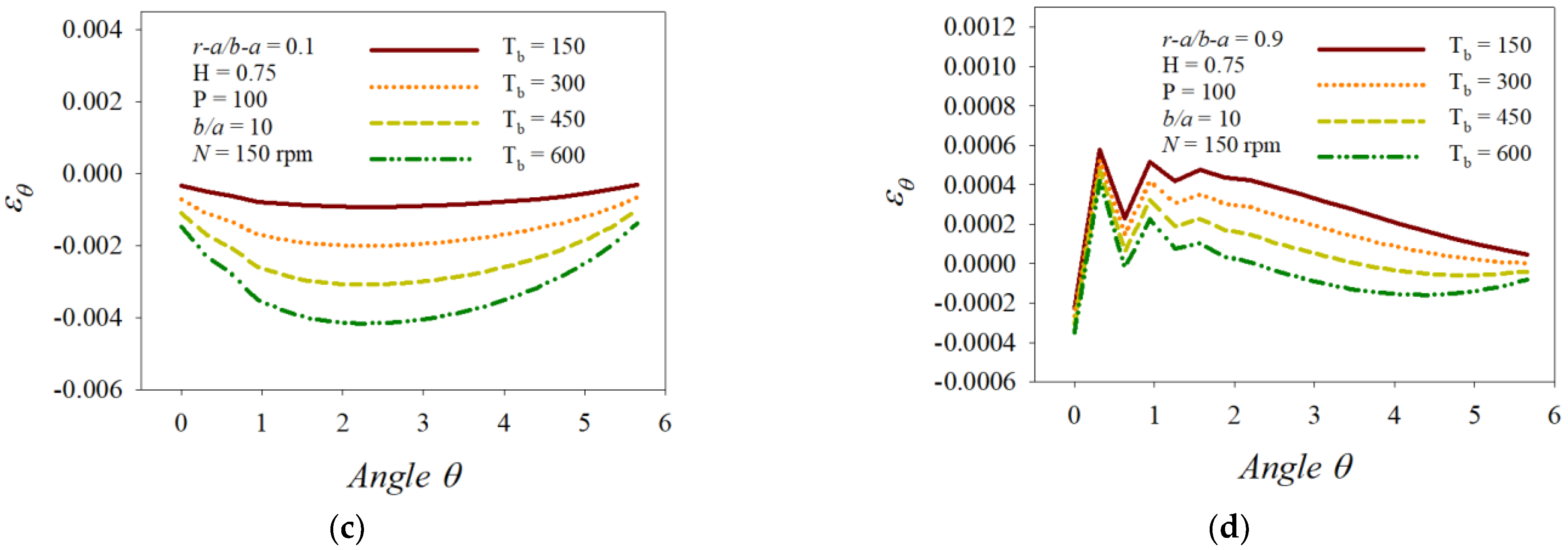
The opposite side to the loading point reacted sensitively and the magnitudes of the displacement, stress, and strain distribution profiles increased over the opposite area.
With the growth in the angular velocity:
(i)
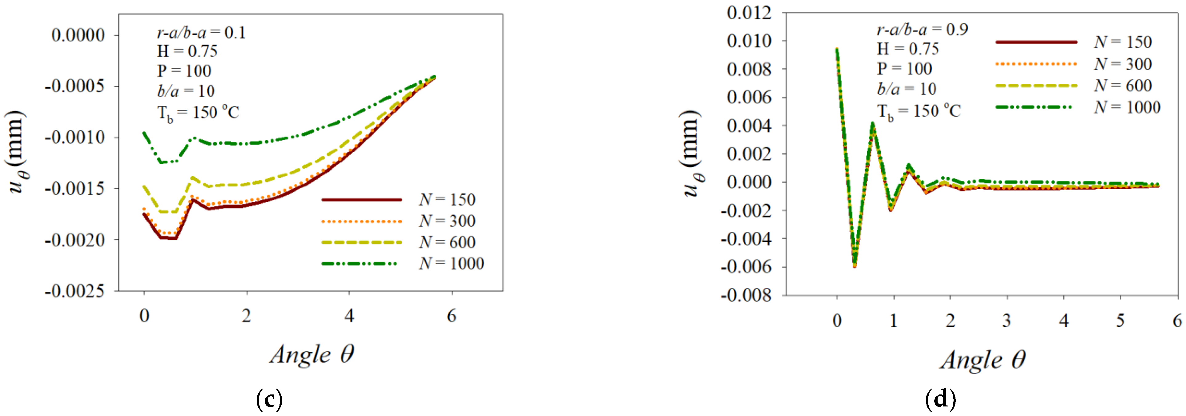
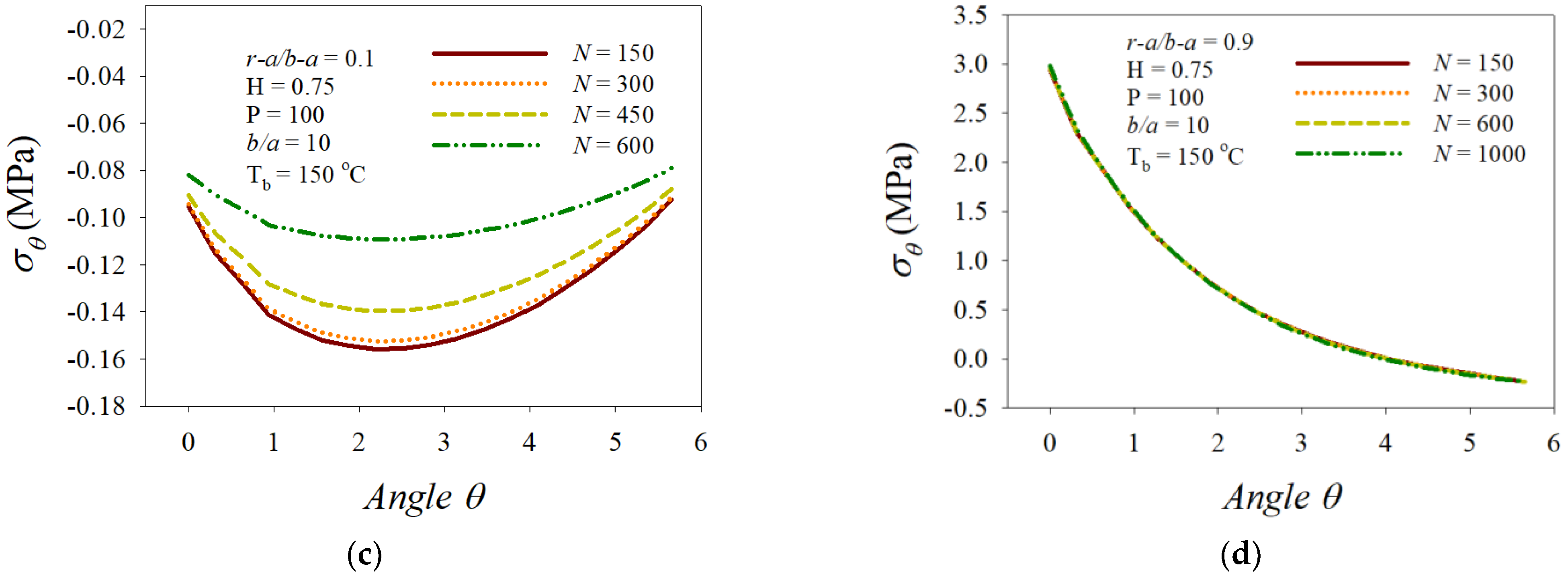
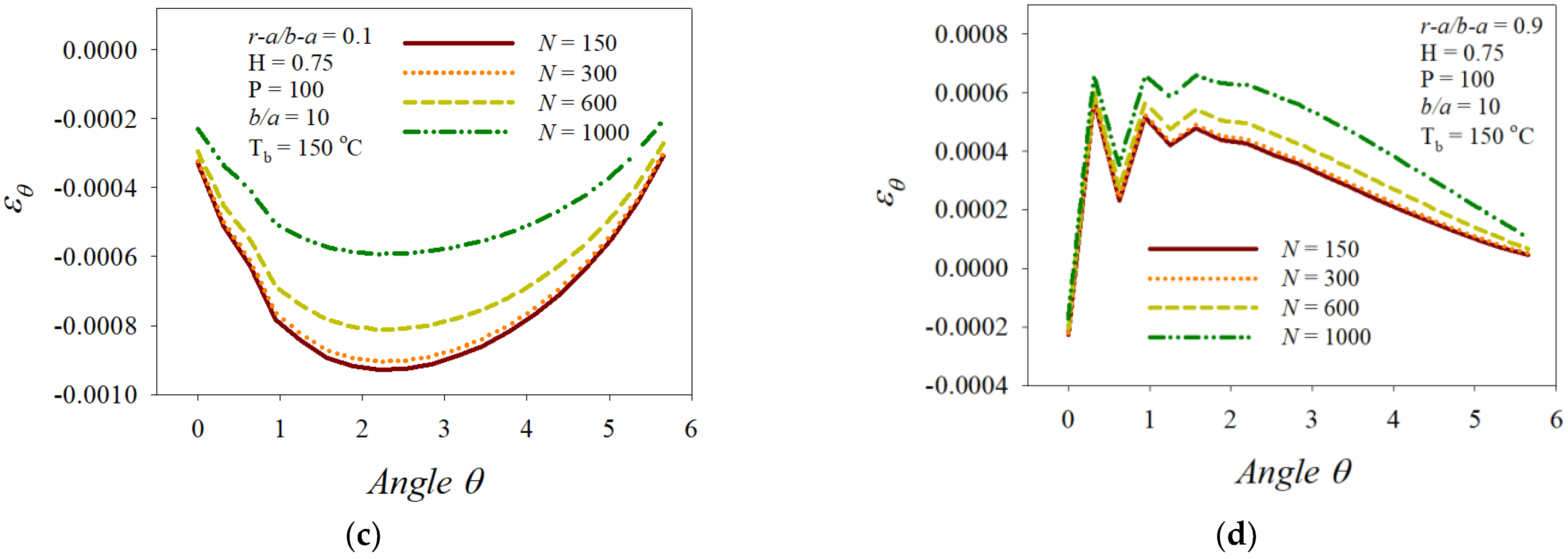
The radial displacement distributions displayed complex change patterns over the opposite side to the loading point.
(ii)
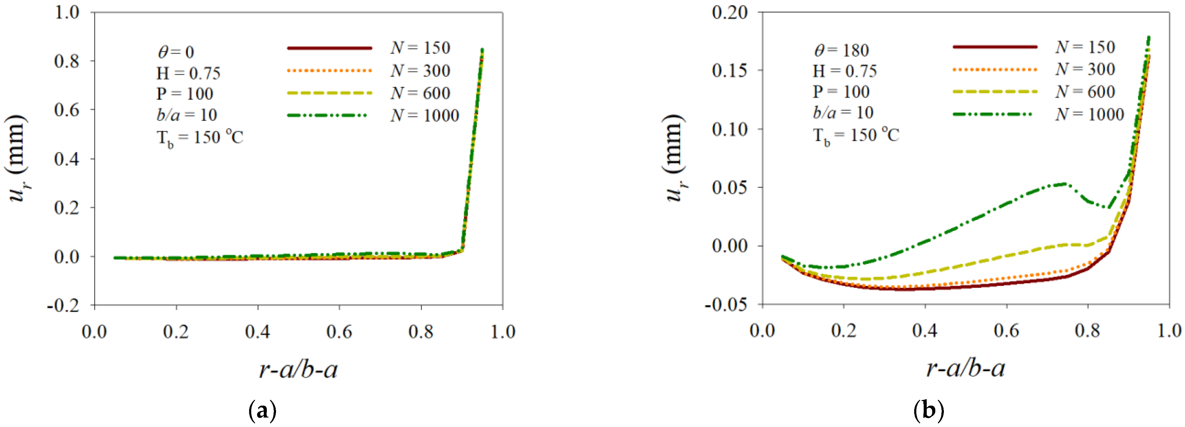
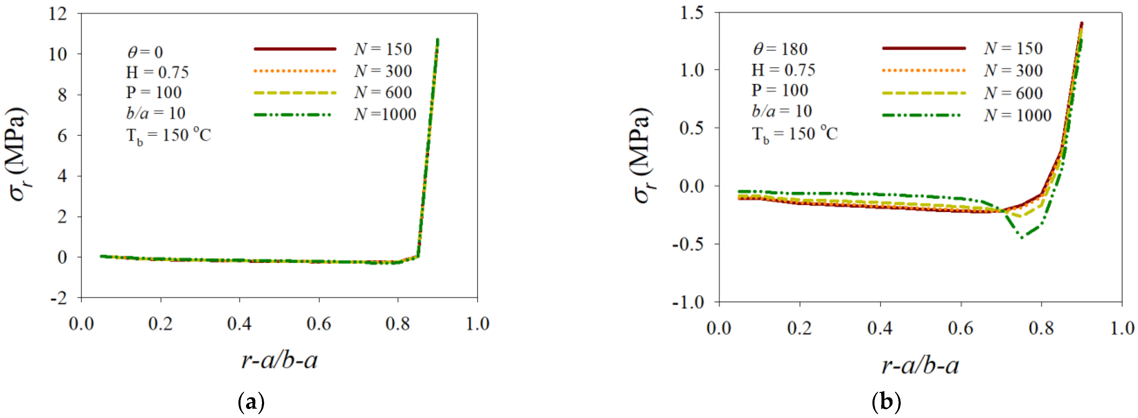
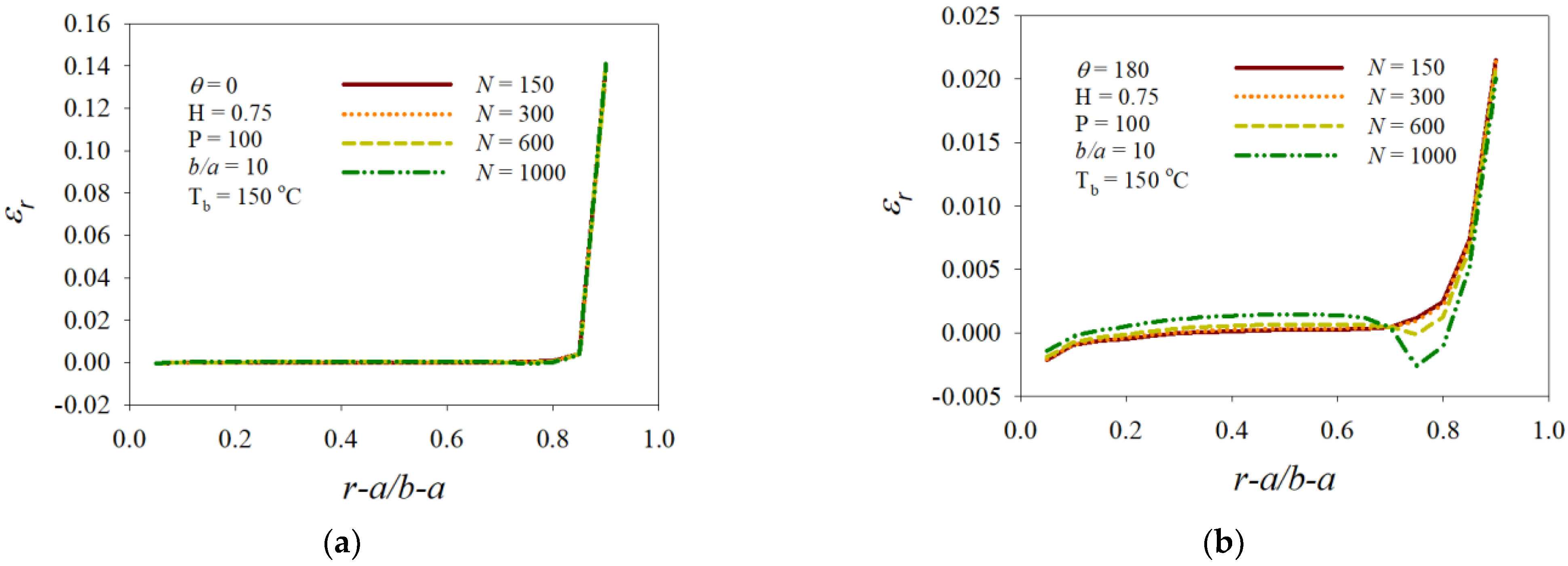
The distribution profiles of the displacement, stress, and strain over the near area of the inner surface moved in the outer-surface direction and the magnitudes decreased.
(iii)
The interval 0.7 < ( r a ) / ( b a )   < 0.9 was the most susceptible area to the variation in the angular velocity, and a dramatic drop appeared at around ( r a ) / ( b a ) = 0.73 of N = 1000.
Through the present study, it was demonstrated that the thermo-elastic characteristics of FG circular disks subjected to contact forces are susceptible to variations in outer boundary temperature and angular velocity. Therefore, both parameters are crucial factors in the design of FG circular cutters or grinding disks undergoing loading pressure to promote proper and reliable thermo-elastic characteristics for practical applications.

Funding

This research received no external funding.

Institutional Review Board Statement

Not applicable.

Informed Consent Statement

Not applicable.

Data Availability Statement

All the data included in this study are available from the corresponding author upon request.

Acknowledgments

This research was supported by Dong-A University.

Conflicts of Interest

The author declares that there are no conflicts of interest.

Nomenclatures

uradial displacement component
v circumferential displacement component
ε r radial strain
ε θ circumferential strain
γ shearing strain
σ r radial stress
σ θ circumferential stress
τ shearing stress
ν Poisson’s ratio
ω angular velocity
Nrevolutions per minute (rpm)
rradius of circular disk
EYoung’s modulus
E 0 initial amount of Young’s modulus
α thermal expansion coefficient
α 0 initial amount of thermal expansion coefficient
ρ density of disk
ρ 0 initial amount of density
β growth rate of E
ϑ growth rate of α
μ growth rate of ρ
T temperature on circular domain
h thickness of homogeneous part
P contact force
a hole radius of circular disk
bouter-surface radius of circular disk

References

  1. Dai, T.; Dai, H.-L. Thermo-elastic analysis of a functionally graded rotating hollow circular disk with variable thickness and angular speed. Appl. Math. Model. 2016, 40, 7689–7707. [Google Scholar] [CrossRef]
  2. Yildirim, S. Hydrogen elasticity solution of functionally-graded spheres, cylinders and Disks. Int. J. Hydrogen Energy 2020, 45, 22094–22101. [Google Scholar] [CrossRef]
  3. Entezari, A.; Filippi, M.; Carrera, E.; Kouchakzadeh, M.A. 3D-wave propagation in generalized thermoelastic functionally graded disks. Compos. Struct. 2018, 206, 941–951. [Google Scholar] [CrossRef]
  4. Pal, S.; Das, D. Free vibration behavior of rotating bidirectional functionally-graded micro-disk for flexural and torsional modes in thermal environment. Int. J. Mech. Sci. 2020, 179, 105635. [Google Scholar] [CrossRef]
  5. Madan, R.; Bhowmick, S.; Saha, K. Limit angular speed of L-FGM rotating disk for both temperature dependent and temperature independent mechanical properties. Mater. Today Proc. 2019, 18, 2366–2373. [Google Scholar] [CrossRef]
  6. Arani, A.G.; Maraghi, Z.K.; Mozdianfard, M.R.; Shajari, A.R. Thermo-piezo-magneto-mechanical stresses analysis of FGPM hollow rotating thin disk. Int. J. Mech. Mater. Des. 2010, 6, 341–349. [Google Scholar] [CrossRef]
  7. Eraslan, A.N. Elastic-plastic deformations of rotating variable thickness annular disks with free, pressurized and radially constrained boundary conditions. Int. J. Mech. Sci. 2000, 45, 643–667. [Google Scholar] [CrossRef]
  8. Sondhi, L.; Thawait, A.M.; Sanyal, S.; Bhowmick, S. Stress and deformation analysis of functionally graded varying thickness profile orthotropic rotating disk. Mater. Today Proc. 2020, 33, 5455–5460. [Google Scholar] [CrossRef]
  9. Bayat, M.; Saleem, M.; Sahari, B.B.; Hamouda, A.M.S.; Mahdi, E. Analysis of functionally graded rotating disks with variable thickness. Mech. Res. Commun. 2008, 86, 283–309. [Google Scholar] [CrossRef]
  10. Yildirim, S.; Tutuncu, N. On the inertio-elastic instability of variable-thickness functionally-graded disks. Mech. Res. Commun. 2018, 91, 1–6. [Google Scholar] [CrossRef]
  11. Mahdavi, E.; Ghaseme, A.; Alashti, R.A. Elastic-plastic analysis of functionally graded rotating disk with variable thickness and temperature-dependent material properties under mechanical loading and unloading. Aetospace Sci. Technol. 2016, 59, 57–68. [Google Scholar] [CrossRef]
  12. Kadkhodayan, M.; Golmakani, M.E. Non-linear bending analysis of shear deformable functionally graded rotating disk. Int. J. Non-Linear Mech. 2014, 58, 41–56. [Google Scholar] [CrossRef]
  13. Khorsand, M.; Tang, Y. Design functionally graded rotating disks under thermoelastic loads: Weight optimization. Int. J. Press. Vessel. Pip. 2018, 161, 33–40. [Google Scholar] [CrossRef]
  14. Zeinkiewics, O.C.; Campbell, J.S. Shape Optimization and Sequential Linear Programming in Optimum Structural Design; Wiley: New York, NY, USA, 1973. [Google Scholar]
  15. Jafari, S.; Hojjati, M.H.; Fathi, A. Classical and modern optimization methods in minimum weight design of elastic rotating disk with variable thickness and density. Int. J. Pres. Ves. Pip. 2012, 92, 41–47. [Google Scholar] [CrossRef]
  16. Saini, R.; Ahlawat, N.; Rai, P.; Khadimallah, M.A. Thermal stability analysis of functionally graded non-uniform asymmetric circular and annular nano discs: Size-dependent regularity and boundary conditions. Eur. J. Mech. 2022, 94, 104607. [Google Scholar] [CrossRef]
  17. Gayen, D.; Chakraborty, D.; Tiwari, R. Stability behavior of two-crack functionally graded shaft in a rotor-disk system: Finite element approach. Mater. Today Proc. 2020, 24, 432–441. [Google Scholar] [CrossRef]
  18. Al-Furjan, M.S.H.; Habibi, M.; Ghabussi, A.; Safarpour, H.; Safarpour, M.; Tounsi, A. Non-polynomial framework for stress and strain response of the FG-GPLRC disk using three-dimensional refined higher-order theory. Eng. Struct. 2021, 228, 111496. [Google Scholar] [CrossRef]
  19. Sathujoda, P. A novel corrosion detection method using wavelet transformed mode shapes of a functionally graded rotor-bearing system. Compos. Part C Open Access 2021, 5, 100134. [Google Scholar] [CrossRef]
  20. Saeedi, S.; Kholdi, M.; Loghman, A.; Ashrafi, H.; Arefi, M. Thermo-elasto-plastic analysis of thick-walled cylinder made of functionally graded materials using successive approximation method. Int. J. Press. Vessel. Pip. 2021, 194, 104481. [Google Scholar] [CrossRef]
  21. Liu, J.; Migórski, S.; Yang, X.; Zeng, S. Existence and convergence results for a nonlinear thermoelastic contact problem. J. Nonlinear Var. Anal. 2021, 5, 647–664. [Google Scholar]
  22. Chawde, D.P.; Bhandakkar, T.K. Mixed boundary value problems in power-law functionally graded circular annulus. Int. J. Press. Vessel. Pip. 2021, 192, 10442. [Google Scholar] [CrossRef]
  23. Howell, P.; Ockendon, J.; Shillor, M. Mathematical theories for two classes of thermoelastic contact problems. Int. J. Solid Struct. 2022; in press. [Google Scholar]
  24. Paoli, L.; Shillor, M. A dynamic thermo-mechanical actuator system with contact and Barber’s heat exchange boundary conditions. Proc. Roy. Soc. Edinb. Sect. A 2021, 151, 734–760. [Google Scholar] [CrossRef]
  25. Cao-Rial, M.T.; Castiñeira, G.; Rodriguez-Aros, A.; Roscani, S. Mathematical and asymptotic analysis of thermoelastic shells in normal damped response contact. Commun. Nonlinear Sci. Numer. Similation 2021, 103, 105995. [Google Scholar] [CrossRef]
  26. Timoshenko, S.P.; Goodier, J.N. Theory of Elasticity, 3rd ed.; McGraw-Hill: New York, NY, USA, 1970. [Google Scholar]
Figure 1. Schematic diagram of functionally graded circular disk model.
Mathematics 10 01518 g001
Figure 2. Schematic diagram for finite volume method: (a) Discretization of circular disk domain, (b) notations of finite control volumes.
Mathematics 10 01518 g002
Figure 3. Validation of finite volume method compared with analytic solution at r = 2 .
Mathematics 10 01518 g003
Figure 4. Effects of outer boundary temperature on the components of displacement: (a) Radial at θ = 0 , (b) radial at θ = 180 , (c) circumferential at ( r a ) / ( b a ) = 0.1, (d) circumferential at ( r a ) / ( b a ) = 0.9.
Mathematics 10 01518 g004aMathematics 10 01518 g004b
Figure 5. Effects of outer boundary temperature on the components of stress: (a) Radial at θ = 0 , (b) radial at θ = 180 , (c) circumferential at ( r a ) / ( b a ) = 0.1, (d) circumferential at ( r a ) / ( b a ) = 0.9.
Mathematics 10 01518 g005aMathematics 10 01518 g005b
Figure 6. Effects of outer boundary temperature on the components of strain: (a) radial at θ = 0 , (b) radial at θ = 180 , (c) circumferential at ( r a ) / ( b a ) = 0.1, (d) circumferential at ( r a ) / ( b a ) = 0.9.
Mathematics 10 01518 g006aMathematics 10 01518 g006b
Figure 7. Effects of angular velocity on the components of displacement: (a) Radial at θ = 0 , (b) radial at θ = 180 , (c) circumferential at ( r a ) / ( b a ) = 0.1, (d) circumferential at ( r a ) / ( b a ) = 0.9.
Mathematics 10 01518 g007aMathematics 10 01518 g007b
Figure 8. Effects of angular velocity on the components of stress: (a) Radial at θ = 0 , (b) radial at θ = 180 , (c) circumferential at ( r a ) / ( b a ) = 0.1, (d) circumferential at ( r a ) / ( b a ) = 0.9.
Mathematics 10 01518 g008aMathematics 10 01518 g008b
Figure 9. Effects of angular velocity on the components of strain: (a) Radial at θ = 0 , (b) radial at θ = 180 , (c) circumferential at ( r a ) / ( b a ) = 0.1, (d) circumferential at ( r a ) / ( b a ) = 0.9.
Mathematics 10 01518 g009aMathematics 10 01518 g009b
Table 1. Mechanical and thermal properties used for analyzing thermo-elastic characteristics of rotating FGM circular disks.
Material/PropertyElastic Module
(MPa)
Thermal Coefficient
( 10 6 / ° C )
Thermal Conductivity
( W / m ° C )
Density
( g / c m 3 )
Substrate (Al)7123.12372.70
Top ( A l 2 O 3 ) 3808.0300.96
Publisher’s Note: MDPI stays neutral with regard to jurisdictional claims in published maps and institutional affiliations.

