1. Introduction
Continuous improvement in the operational characteristics of gas-turbine engines and reducing the time and cost of their creation require the use of the latest techniques aimed at improving the strength and thermal state properties of the engine rotor and stator elements, increasing the compressor stall margin, and improving the emission, among others. One of the most important stages for the development of new technologies in an engine-building enterprise is research testing of a gas generator with simulation of the core inlet conditions for a full-size engine [
1].
At present, the major disadvantages of such tests are the prevailing manual operations, which require high qualifications and the well-coordinated work of personnel, having a multi-iteration nature, and as a consequence, leading to significant time taken to evaluate the required thermo gas dynamic parameters at the inlet of the test gas generator [
1,
2]. Therefore, one the most effective solutions is to increase the level of test automation.
There are two main directions to increase the test automation level, namely, improving the test system hardware and algorithmic tools [
3,
4,
5]. The improvement in hardware is aimed, first of all, at the use of modern high-performance control structures with high-precision, reliable sensors of process parameters, registration, and storage systems. Studies by [
3,
4] have introduced advanced hardware simulators and emulators, which allow for the generation of signals from a control object without the need of a real engine after the dynamic behavior of the system has been identified through measurements.
Improvement in the algorithmic means provides for the use of unique control and monitoring algorithms that provide additional information on changes in process parameters. For example, in [
5], a real-time engine model based with SIMULINK and a test bench were developed to verify the performance of the electronic engine control unit of a turbofan engine. Of greatest interest are solutions aimed at increasing the tests’ automation level without involving significant material resources due to the maximum use of the technical potential of the existing system and a significant complication of its algorithmic component.
Thus, the solution of this problem is impossible without the use of modern algorithmic solutions and control methods [
6,
7,
8]. These methods are not only about exploring the role of and need for automated and precise control systems in engineering by employing root locus design, frequency, and response design [
7,
8]. At the moment, the industry demand is to provide the required thermo gas dynamic parameters at the inlet of the test gas generator under conditions of a limited amount of information and ever-changing properties [
9,
10,
11].
The gas turbine equipment is considered as a complex dynamic control object [
9] and the design method has to ensure the stability and required quality of transient processes at different acceleration modes [
10,
11]. An algorithmic approach based on the concept of constant eigenvectors and analytical design of the control system is known [
10]. Another of the decisions concern fractional-order sliding-mode control scheme based on a recurrent neural network (e.g., two-hidden-layer recurrent neural network [
12]). This neural network is a fully regulated network, which can be simply considered as a combination of a fuzzy neural network and a radial basis function neural network to improve the accuracy of a nonlinear approximation, so it has the advantages of these two neural networks [
13].
The purpose of this article is to develop control system algorithms to test the process of the bypass turbojet engine gas generator with simulation of the required input thermo gas dynamic parameters.
2. Materials and Methods
An increase in the share of research tests of the bypass turbojet engine gas generator (hereinafter referred to as a gas generator) at the initial design phases requires the organization of tests with minimal financial and material costs. One effective solution is the use of specialized test complexes with the simulation of the required input thermo gas dynamic parameters such as temperature, pressure, and flow rate of the working fluid [
14,
15].
One example is a specialized test complex for the study of a gas generator [
15]. The developed complex implements the concept of determining the simplest and most economical means of obtaining a working fluid with the required thermo gas dynamic parameters to test a predetermined object list of different thrust (power) and purpose.
The specialized test complex under consideration [
15] is based on the process of obtaining a working fluid with the required thermo gas dynamic parameters, in which the representation of these parameters is performed on the basis of a modified bypass turbojet engine with separate flows of the gas generator and bypass duct, and with the independent working fluid bleed from the bypass duct of a technological bypass turbojet engine (hereinafter referred to as a technological engine). The working fluid of the technological engine bypass duct through the working fluid supply system enters the inlet of the test gas generator, which ensures the simulation of the input thermo gas dynamic parameters. In turn, the working fluid supply system is an air duct system containing devices to bypass the working fluid into the atmosphere, namely, a controlled bypass damper and discrete bypass valves.
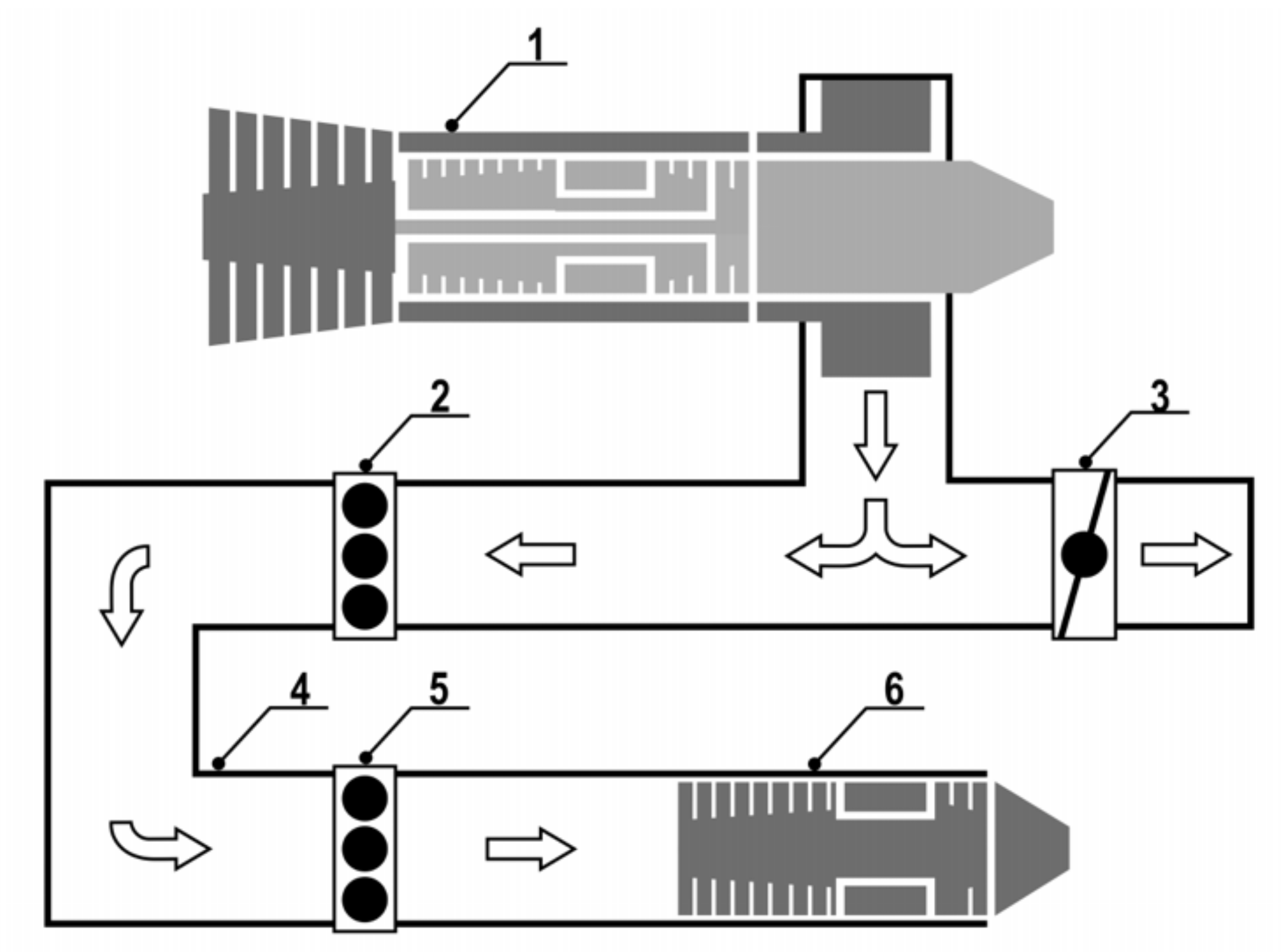
Figure 1 shows the schematic diagram of a specialized test complex.
In
Figure 1, the following designations are adopted: 1—technological engine; 2, 5—discrete bypass of the working fluid into the atmosphere; 3—controlled bypass of the working fluid into the atmosphere; 4—air duct system; 6—gas generator.
The critical weakness of such test complexes is that the provision of the required input thermo gas dynamic parameters, as a rule, is carried out in manual mode, which is accompanied by a continuous change in the complex technical parameters, leading to a significant increase in the costs of the tests and complication. For example, a significant limitation when changing the technological engine operating mode and the amount of working fluid bypassing into the atmosphere is the need to maintain the stall margins of the technological engine compressor in a limited, dynamically changing operational envelope, and, first of all, is associated with the design of a specialized test complex. Therefore, there is a high probability of emergency situations due to the manual control of the gas generator operating mode, the technological engine, and the working fluid supply system; this is required to ensure the coordinated operation of the complex elements in the conditions of rapidly changing processes. Thus, there is a need to develop an automated test control system, namely, its most science-intensive component—the development of control algorithms for the process under consideration.
The test complex should provide a simulation of the gas-dynamic parameters corresponding to the required characteristics of the working fluid at the inlet of the gas generator of the designed full-size engine under various operating modes, namely, maintaining the temperature (
TGG_REQ) and pressure (
PGG_REQ) of the working fluid. The required parameters can be presented as functional dependencies of the gas generator operating modes (
ModeGG) and the required thermo gas dynamic parameters at the inlet of the designed engine such as the temperature (
TBTE_REQ) and pressure (
PBTE_REQ) of the simulated atmosphere Equations (1) and (2):
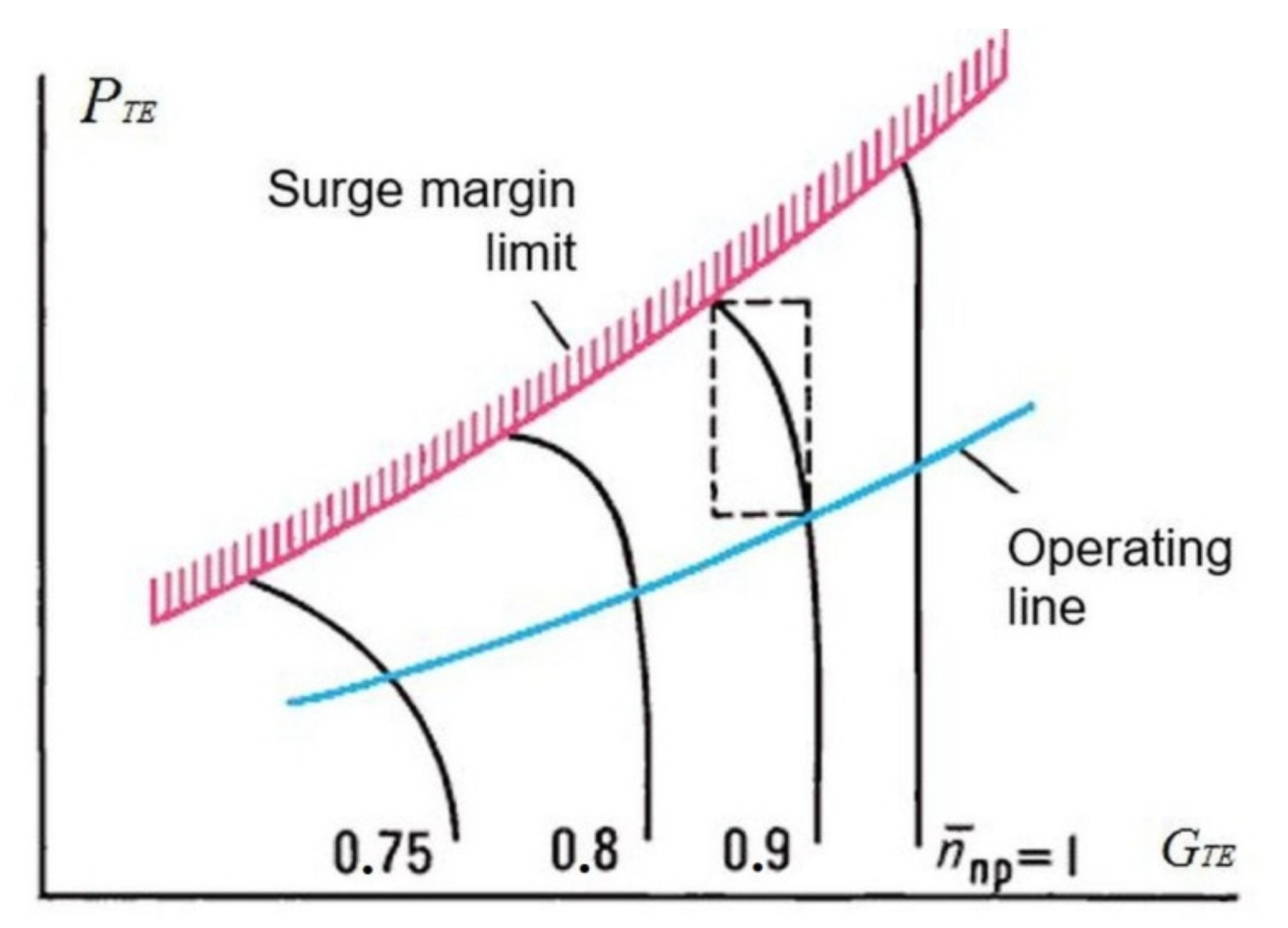
The primary mean to simulate the required gas-dynamic parameters is to provide a joint variation in the technological engine operating mode and the amount of working fluid bypassing into the atmosphere. Providing the required parameters results in a change in the temperature, pressure, and flow rate of the working fluid through the technological engine, which affects the position of the operating point relative to its operating line and is described as dependency between the pressure ratio (PTE) and the flow rate of the working fluid (GTE) through the compressor technological engine.
Figure 2 shows the generalized characteristic of the technological engine compressor. Ensuring the stall margins of the technological engine is a priority task and characterizes the normal operation of the entire test complex when adjusting the parameters at the gas generator inlet.
Therefore, the main task of the developed process control system during operation is to provide the equality of the actual values of temperature TGG and pressure PGG to the set values of temperature TGG_REQ and pressure PGG_REQ of the working fluid at the gas generator inlet while maintaining the operating point position in the permissible area of the technological engine operating envelope.
Thus, it is necessary to provide maintenance of the four main state variables ТGG, PGG, PTE and GTE in the presence of only two control actions: the technological engine operating mode and the amount of the working fluid bypassing into the atmosphere. However, due to the design features of the technological engine, the change in the operating mode is carried out by discrete commands that determine the change in fuel consumption at a slow or fast rate. Due to the design features of bypassing the working fluid into the atmosphere, the rate of the working fluid bypass change is an order of magnitude less than the change rate of the rest of the control actions of the complex. An external disturbance for the control system is a change in the gas generator operating mode, which affects all four controlled parameters. For example, an increase in the gas generator operating mode with the unchanged remaining elements of the complex causes a decrease in the temperature ТGG, pressure РGG, and also causes a decrease in the operating point on the technological engine gas-dynamic characteristic.
The test complex under consideration is a substantially nonlinear system, since it includes a technological engine and a gas generator, which are nonlinear objects with internal cross-links as well as a working fluid supply system, which is an object with significant inertia and nonlinear flow characteristics, determined by the current position controlled bypass of the working fluid to the atmosphere and the pressure drop across the controlled bypass of the working fluid to the atmosphere.
It is also worth noting that the test complex, as a control object, is a multi-variable system in which each controlled variable substantially depends on other control actions. In this case, the mutual relationships between the variables cannot be neglected, since the object represents several dynamic links, connected by taking into account the cross-links between controlled variables, control actions, and disturbances, where each of the control actions of the complex affects all state variables.
Finally, the test complex has significant
non-stationarity, since all parameters of the system have different static and dynamic properties, both depending on the mutual configuration of the operation modes of the complex elements, and depending on their operation duration. For example, the exhibition of various properties of a technological engine associated with a change in the permissible area of the technological engine operating envelope depends on the operating modes of the working fluid supply system or different degrees of warming up of the test complex. Unlike the known approaches [
5,
10,
13], this factor is the key one.
Next, we performed the selection and justification of control methods for the implementation of control algorithms. Taking into account the considered analysis of the control object properties, we proposed comparing the conventional methods of automatic control theory and control methods based on the theory of fuzzy logic.
Conventional methods of control theory based on the assumption that a control object can be represented as serially connected linear dynamic links (proportional, integrating, differentiating, non-periodic, oscillatory, etc.) [
16]. In the structural–parametric synthesis of the control system, each link of the object must correspond to a link with a return transfer function as part of the controller [
9]. To control objects of a low order, typical regulators are usually used, the names of which correspond to the names of the dynamic links: the simplest P-, I-, D-controllers are combined into a controller of the PI, PD, PID type. In [
17], the issue of the parameter setting of conventional PID controllers was considered, the topology of the PID controller based on the observer was introduced, and examples of modeling were given. The study in [
18] presented the structure and optimal parameter setting of the matrix PID controller. In [
19], a new approach was proposed to improve the robust properties of PID controllers. An overview is provided in [
20] of the various types of PID controllers that are commonly used in industrial automation, and their advantages and disadvantages were considered. The study by [
21] presented the setting of the speed controller of a DC motor based on the modified Ziegler-Nichols method, and [
22] investigated a modification of the Ziegler–Nichols method to set a digital PID controller.
The popularity of using conventional methods for the development of controllers is explained by the arrangement simplicity, functional clarity, and suitability for many practical tasks, for example, control of the transport robot drive [
23], temperature control during sintering in spark plasma [
24], optimization of control processes for cooling plants [
25], control of a three-phase inverter in uninterruptible power supplies [
26], among others.
Depending on the type and order of the control object as well as the relationship between its time responses, the controller was set according to the standard criteria and methods [
27]. The criterion selection is based on understanding the control purpose and is not formalized in itself. It is also necessary to consider that when using typical controller settings, overcorrection may occur in the system, for which compensation is necessary to refine the settings or an additional filter is used at the controller input. A typical coefficient controller setting is performed for the area of low coordinate deviations and a low input reference, in which case the controller does not enter saturation. However, with large reference input or disturbing action, the controller can saturate, which must be taken into account in the synthesis. Therefore, to limit the derivative controlled coordinate value, an intensity driver is usually installed at the input of the controller. As a result, properties of the control object such as nonlinearity, multi-variability, and non-stationarity can significantly limit the area of application of conventional synthesis methods and can seriously complicate the controller structure and setting. For example, problems arising from the object nonlinearity are solved by system linearizing or introducing correcting nonlinear links into the controller structure [
28]. However, linearization methods are of limited use, and in many cases, require linearization over a large number of points [
29].
When developing a controller for a multi-variable system, it is necessary to provide independence of the control channels, so that a change in one of the controlled parameters does not lead to a change in others. The property of system independence is achieved by introducing additional corrective feedbacks. The system non-stationarity tasks are solved by using adaptive control [
30], which allows one to synthesize a controller, the structure or settings of which change during the control process depending on the object parameters and properties.
The use of each of these methods separately implies the introduction of additional tools, the use of which is superimposed on the basic control algorithm. The use of all methods at the same time makes the control algorithm practically unrealizable. Thus, notwithstanding that in automatic control theory the synthesis of a controller using conventional methods is performed in a strictly formal way, in practice, such synthesis largely depends both on the properties of the control object and on the experience of the designer. This has been confirmed by a large number of publications devoted to the synthesis of such controllers [
20,
21,
22,
23,
24,
25]. Therefore, it can be assumed that if the synthesis and adjustment of the controller coefficients is a formalized procedure and not a creative process, then such a number of publications would be unjustified.
The whole set of problems arising from the implementation of control algorithms for a complex object such as the test complex under consideration can be solved using modern methods of the fuzzy control theory [
7], which is proposed to be highlighted later.
Despite the indicated complexity of the considered control object, in practice, the specialists conducting the tests carry out the control of the object manually on the basis of a mathematical representation of the ongoing physical processes and knowledge about the particularity of the complex operation, accumulated over many tests, which together constitutes
expert experience. Consequently, to create a control system for the testing process, the fuzzy logic theory can be used [
31,
32], which was developed to translate expert experience into the terms of mathematical logic. In this case, the initial data for the development of control algorithms were the mathematical representation of the object and the experience of experts. The control action is determined by the rule base, which is analogous to solutions based on the expert experience. Thus, control algorithms based on fuzzy logic theory can be developed primarily by experts and engineers in the fields of design and testing of gas turbines.
As indicated earlier, the conventional control methods require an analytical synthesis procedure to the controller setting. To implement this procedure in practice, a high-precision mathematical description of the object in the form of linear differential equations is required. Moreover, if the initial data of the required accuracy are absent, which is quite common, then there are heuristic approaches for the arrangement controllers, which are reduced to the selection of particular solutions in the neighborhood of a particular point. Consequently, the selection of conditions for these particular solutions is completely equivalent to a set of conditions for the rule base of fuzzy control. The defuzzification process, used to transform a fuzzy set into an explicit value at the controller output, can in a sense be considered an analogue of the selection of control loops—selection that is conventionally used in multi-variable system control. It should be noted that for control algorithms based on fuzzy logic, a set of rules and membership functions explicitly determines the behavior of the system, and if additional conditions arise, it can be easily modified during setup or even operation. When modifying conventional control methods, consideration of additional conditions has been transferred to the level of the practical implementation and design of the controller architecture (use of correcting links and connections, selection of loops, etc.) and may require multiple repetitions of a complex procedure of structural–parametric synthesis and adjustments.
Thus, fuzzy control methods are a reasonable alternative to conventional synthesis methods. It is reasonable to use them for control systems with incomplete or rapidly changing information on the object and with high complexity of the object in the presence of significant multi-variable, nonlinearity, and non-stationarity of its properties and characteristics, which cannot be compensated by the introduction of corrective links and feedback. There are many publications where this approach has been implemented for a variety of objects, for example, in control systems of an aircraft [
33], a wind generator [
34], a gas turbine engine [
35], in a hydrogen vehicle power system [
36], in the control system of the tension of an insulating tape in a machine for winding a transformer [
37], while controlling the speed of a DC motor [
38], in a digital twins of the water cooling system [
39], and in a standalone electric vehicle charging station [
40].
Thus, to eliminate the many difficulties in the development of the controller architecture and solve the task of analytical synthesis optimization, we propose the implementation of an automated test control system based on algorithms of fuzzy logic theory.
3. Results
3.1. Basic Data for Formation the Rule Base of the Logical Control
As applied to the test complex, its behavior as a control object is mainly determined by thermophysical and gas-dynamic processes. Therefore, as a collection of behavior concepts, it is necessary to take into account the following simple facts:
increasing/decreasing the operating mode of the process engine increases/decreases the temperature TGG and the pressure PGG at the gas generator inlet;
increasing/decreasing the operating mode of the process engine causes a shift in the operating point up/down on the gas-dynamic characteristic line of the process engine compressor;
increase/decrease in the amount of the working fluid bypassing into the atmosphere causes a decrease/increase in the temperature TGG and the pressure PGG at the gas generator inlet; and
increase/decrease in the amount of the working fluid bypass causes a shift in the operating point up/down on the gas-dynamic characteristic line of the process engine compressor.
It is also necessary to take into account the more subtle aspects of the behavior of the control object, which are also components of expert experience. We list the most typical of them:
changing the operation mode of the process engine has a greater effect on the change in temperature at the gas generator inlet TGG, and the change in the amount of the working fluid bypass has a greater effect on the change in pressure at the gas generator inlet PGG, which is established on the basis of mathematical calculations;
changing the mode of the process engine to regulating the temperature at the gas generator inlet TGG should be performed only after the position of the process engine operating point has stabilized (i.e., the operating point is inside the control band of the gas-dynamic characteristics of the process engine compressor for a given time);
change in the operating mode of the process engine must not be lower than the value corresponding to the “Idle” mode of the process engine and not exceed the value corresponding to the “Maximum” mode of the process engine;
change in the amount of the working fluid bypass to regulate the gas generator inlet pressure PGG should be in an area significantly smaller than the available area of change in the amount of the working fluid bypass. However, locating the working fluid bypass at any point in the available area is possible only if the operating point remains in the range the surge margin of the process engine operating envelope;
critical deviation of the gas generator inlet temperature TGG from its preset value TGG_REQ (the next order value from the maintenance accuracy) cannot be fully compensated by changing the process engine operating mode, since the available range of the working fluid bypass is too low to maintain the operating point in the range of the surge margin of the process engine operating envelope; and
critical approach of the operating point to the boundaries of the surge margin of the process engine operating envelope (the value corresponding to the order of the maintenance accuracy) requires the combined action of all control elements of the complex.
3.2. Description of the Controller Based of Fuzzy Logic Theory
Thus, as a result of generalization of the considered aspects of the expert experience, it is possible to determine the input and output variables of the controller, developed on the basis of the theory of fuzzy logic (hereinafter referred to as the logical controller). For each parameter, it is necessary to set linguistic variables and, as a result, set a base of fuzzy rules that form the basis of the control algorithms.
Then, the following variables must be applied to the logical controller input, characterizing the state of the object under consideration:
Dlt_Т—deviation of the temperature ТGG from the specified TGG_REF (temperature regulate error);
Dlt_Р—deviation of the pressure РGG from the specified PGG_REF (pressure regulate error);
Dlt_OP—deviation of the operating point position (Operating Point) of the technological engine from the centerline (Reference Line), calculated relative to the specified boundaries of the surge margin of the process engine operating envelope;
Derivative_OP—rate of change of position (derivative) of the operating point relative to the Reference Line;
Position_BV—current value of the regulated working fluid bypass; and
Mode_TE—current operating mode of the process engine.
In turn, the values of the input variables are converted by fuzzification blocks using triangular or trapezoidal membership functions.
The real rules base of the logical controller contains several dozen rules that take into account various aspects of the control object behavior, the control particularity with almost fully closed (or open) of the working fluid bypass, and the base also includes specific rules related to the techniques of the gas generator test.
As a result of applying the rules, we obtained a set of fuzzy values for the output linguistic variables. Defuzzification makes the transition from fuzzy values to specific control signals.
As a result, the following control signals to the actuators of the test complex will be generated:
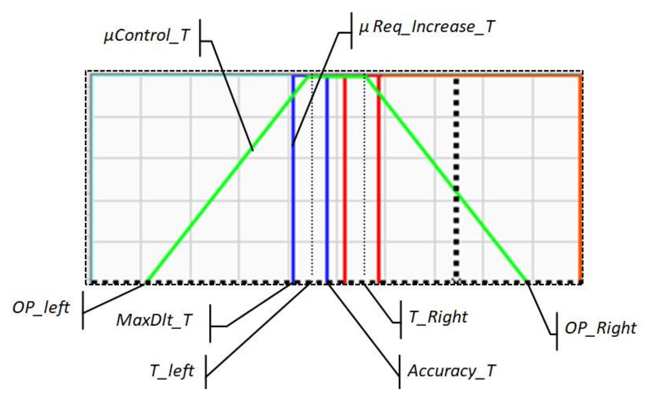
For example, consider the formation of several fuzzy rules that make a significant contribution to the formation of the controller output variables. The rules are presented in simplified form, without taking into account additional and specific conditions. First, fuzzy terms need to be described, characterized by the membership functions used in these rules.
For the input linguistic variable
Dlt_T, define the terms
‘Control_Т’ and
‘Req_Increase_T’, which we will use in the selected rules.
Figure 3 shows the membership function graphs for the terms
‘Control_T’ and
‘Req_Increase_T’.
The term ‘Control_T’ has the following meaning: if the temperature deviation Dlt_T is within the specified limits, then we adjusted the temperature, otherwise, we only adjusted the position of the operating point.
The following membership function is specified for the term
‘Control_T’:
where
T_left, T_right are the boundaries of the temperature regulation zone (left and right) and
OP_left, OP_right are the boundaries of the operating point position regulation zone (left and right).
The term ‘Req_Increase_T’ has the following meaning: if the temperature deviation is less than the lower limit of the specified regulation accuracy Accuracy_T, then the temperature needs to be increased.
The following membership function is specified for the term
‘Req_Increase_T’:
where
MaxDlt_T is the maximum possible temperature deviation and
Accuracy_T is the specified temperature regulation accuracy.
For the linguistic variable Dlt_OP, define the term ‘Req_Increase_OP’, which is used in the selected rules.
The term ‘Req_Decrease_OP’ has the following meaning: if the deviation of the operating point position Dlt_OP is greater than the upper limit of the dead band, then the position of the operating point must be decreased.
The following membership function is specified for the term
‘Req_Increase_OP’ (
Figure 4a):
where
Upper_Line is the upper limit of the dead band when regulation of the operating point position, which is calculated dynamically relative to the centerline.
Considering the derivative of the operating point position is analogous to the differential component for a PID controller.
For the linguistic variable Derivate_OP, define the term ‘Fast_Fall_OP’, which is used in the selected rules.
The variable Derivate_OP belonging to the fuzzy set ‘Fast_Fall_OP’ means that the rate of change (derivative) of the operating point position is less than the permissible value.
The following membership function is specified for the term
‘Fast_Fall_OP’ (
Figure 4b):
where
Zone_Fall is the limit of the control system sensitivity to the rate of decrease in the operating point position.
Since the control of the test bench actuators (the process engine operating mode the value of the working fluid bypass) is carried out using discrete signals, the membership functions for the output terms will have a sigmoid form.
The following membership function is specified for the term ‘
RUD_QF’:
The following membership function is specified for the term
‘BV_Open’:
As a result, we can write down the simplified fuzzy rules as follows:
If ‘Dlt_T’ is ‘Req_Increase_Т’ and ‘Dlt_T’ is ‘Control_Т’ and ‘Dlt_OP’ is not ‘Req_Decrease_OP’ then ‘RUD’ is ‘RUD_QF’.
If ‘Dlt_OP’ is ‘Req_Decrease_OP’ and ‘Dlt_T’ is ‘ControlТ’ and ‘Derivate_OP’ is not ‘Fast_Fall_OP’ then ‘BV’ is ‘BV_Open’.
In fact, the listed rules are expert experience in managing the test complex, which can be formulated as follows:
If an increase in temperature is required at the gas generator inlet, while the temperature deviation from the set one is not very large and the position of the process engine operating point does not require its decrease, then we increase the process engine operation mode (we increased the fuel flow of the process engine).
If the operating point position is required to decrease, while the temperature deviation from the set one is not very large and the decrease rate of the process engine operating point is not less than the set one, then we increase the percentage of the working fluid bypass.
The presented rules do not contain additional conditions that affect the formation of real control actions. In total, the current version of the logical controller rule base contains more than twenty rules that take into account all aspects of the system’s behavior, described on the basis of expert experience.
4. Discussion
To examine the operability and efficiency of the developed logic controller, a simulation was carried out using a specialized software package [
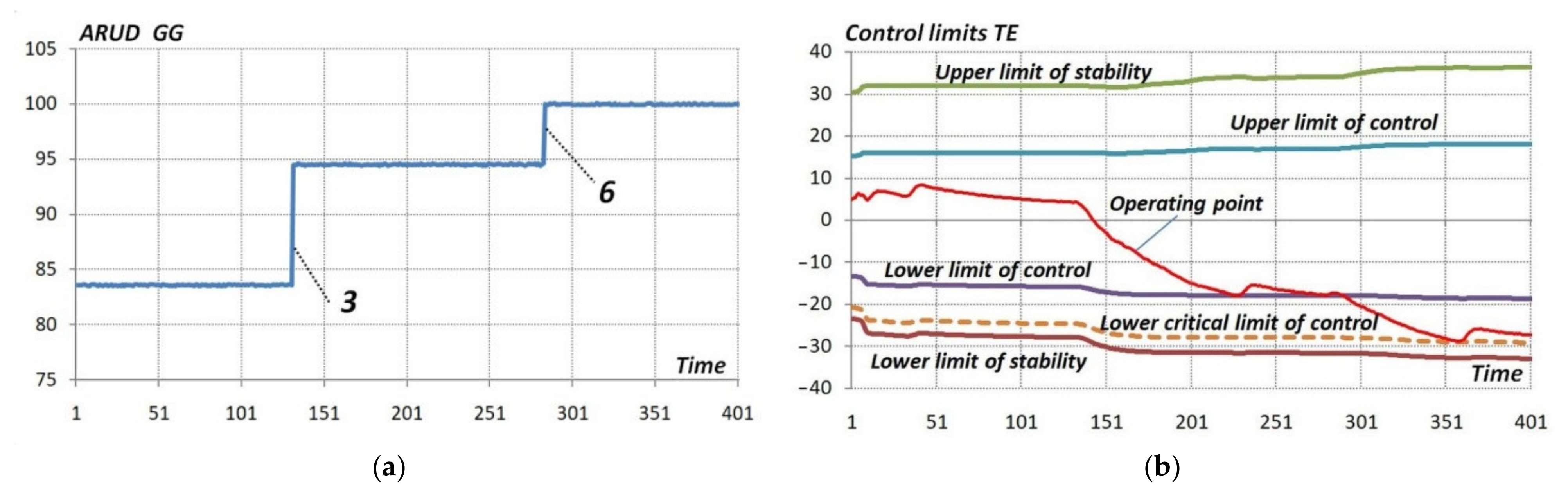
31]. As an external disturbing action was taken, there was a change in the gas generator operating mode, which was settled by the position of the gas generator throttle (
ARUD_GG).
As noted earlier, the main task of the developed control algorithms is to maintain, with a certain accuracy, the specified temperature at the gas generator inlet, which is determined by the functional dependence on the gas generator mode: TGG_REF = f(ARUD_GG). Thus, the controller should minimize the temperature deviation at gas generator inlet TGG from the set TGG_REF (temperature regulate error Dlt_T = TGG_REF − TGG).
When regulating the temperature at the gas generator inlet, the controller must, as a priority, ensure the stall margin of the process engine compressor (i.e., ensure location of the process engine operating point in area limited by the specified stall margins). At the same time, the fuzzy rules are formulated in such a way that the operating point of the process engine compressor must be kept between the specified upper and lower limits of the dead band (regulation). If the operating point approaches the stall margin limits of the process engine (when crossing the critical control limits), it is necessary to ensure a return to the acceptable operating area, neglecting all other conditions.
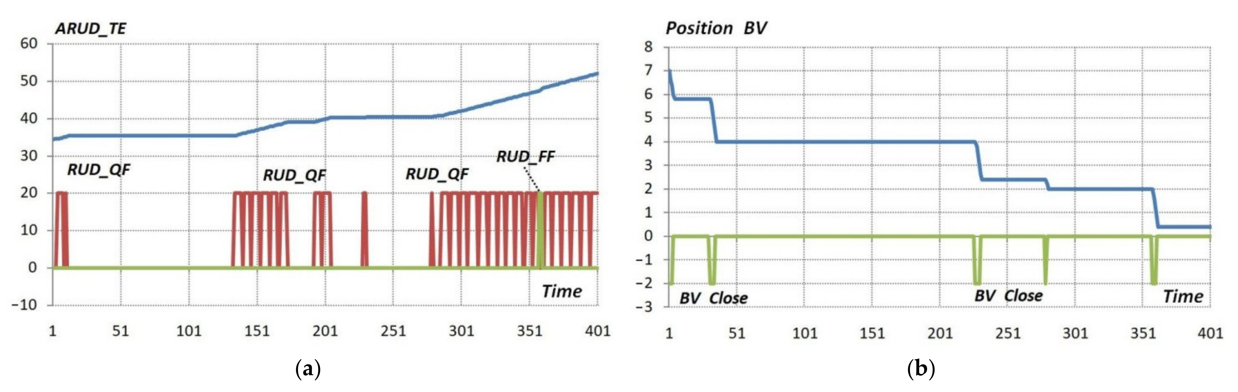
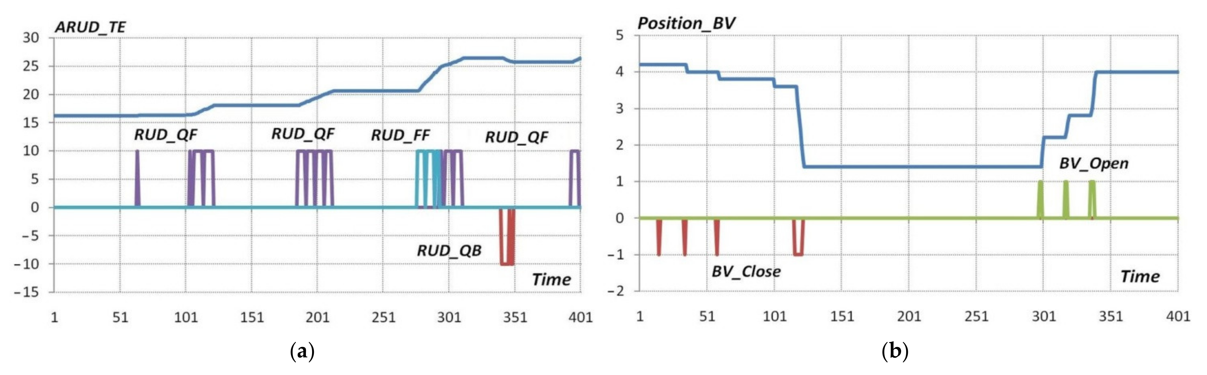
As a result of the logical controller actions, the control of the process engine operating mode is formed: increase/decrease in the fuel supply through discrete change in the throttle lever position АRUD_TE with forward/backward signals at fast (RUD_FF/RUD_QF) or slow (RUD_FB/RUD_QB) rates and control of the working fluid bypass amount (Position_BV) with signals for opening (BV_Open) or closing (BV_close) the regulated working fluid bypass into the atmosphere.
Since the complete cyclogram of tests is too long for its analysis within the article, it is proposed to consider only a few of the most characteristic control sections that illustrate the particularity of the logical controller operation.
For a better perception of information on the action of control algorithms, the graphics with the simulation results can be divided as follows:
the set operating mode of the gas generator (the value of the throttle position) and the set limits of the process engine modes and operating point position;
current values of parameter deviations at the gas generator inlet from the specified value;
illustration of the contribution of the rules to the control of the process engine operating mode and the working fluid bypass value; and
current position and control signals for controlling the process engine mode, current value, and control signals to control the working fluid bypass value.
To analyze the action of the logical controller, the contributions of various rules to the overall behavior of the system are presented. A positive or negative value of the contribution of the rule corresponds to an increase/decrease in the fuel supply of the process engine and the opening/closing of the regulation of the working fluid bypass into the atmosphere. The different weights of the rules on the graphs indicate the fuzzy nature of the sets present in the rules. Contributions of different rules are plotted in different colors. On all graphs, the parameters are presented in relative units, the time scale is conditional, the time step of the points is 0.2 s, and was set in the simulation environment.
Let us next consider the description of the control system operation and explain the behavior of the logical controller at the expert level.
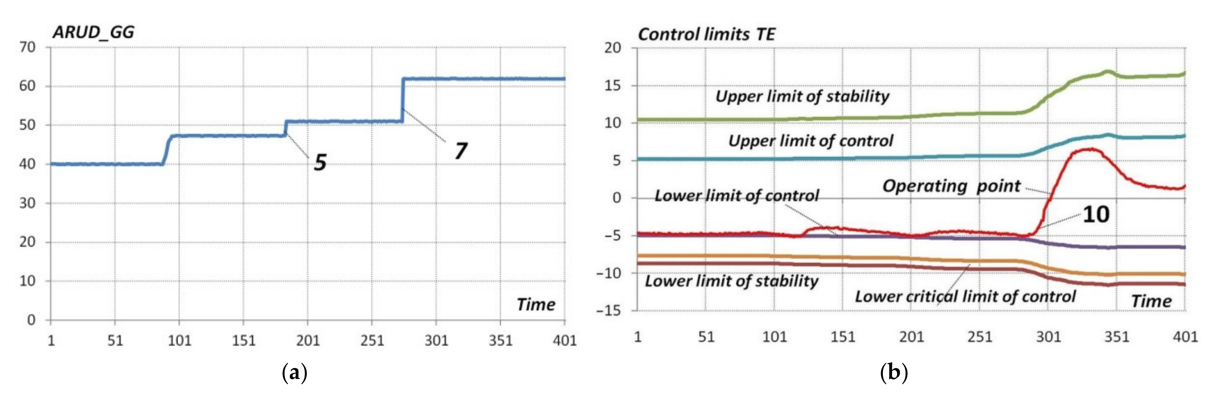
4.1. Analysis of the Controller Action near the Gas Generator “Idle”Mode
Figure 5,
Figure 6,
Figure 7 and
Figure 8 show the graphs of changes in the main parameters of the logic controller and the test complex near the gas generator “Idle” mode.
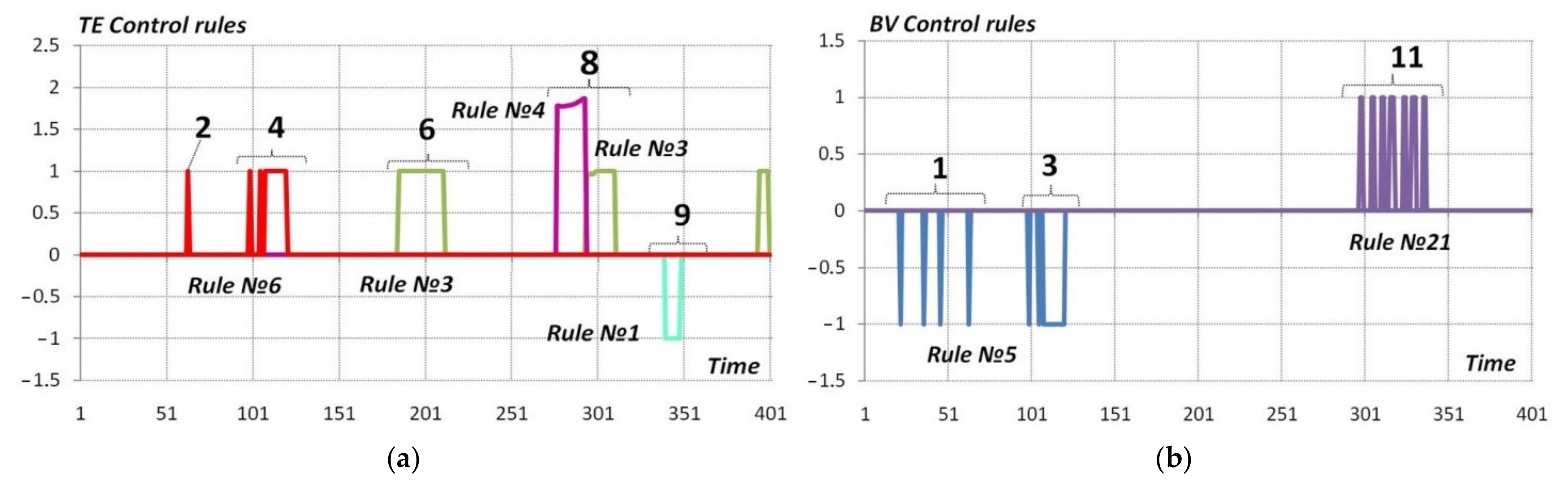
At the beginning, the deviation of the operating point position (
Figure 5b) reaches the lower limit of sensitivity of the control system and to increase the operating point.
Rule no. 2 (position 1 in
Figure 7b) repeatedly instructs one to close the regulated working fluid bypassing into the atmosphere (signal
BV_close,
Figure 8b). As a result, the regulated working fluid bypassing into the atmosphere is almost closed (
Figure 8b). To ensure the continued increase in the operating point,
rule no. 6 (position 2 in
Figure 7a) generates a signal to slow the increase in the process engine fuel flow (signal
RUD_QF,
Figure 8a). Next, repeat the rules’ action and signals to closethe working fluid bypassing into the atmosphere (position 3,
Figure 7b; signal
BV_close,
Figure 8b) and to increase the process engine fuel flow (position 4,
Figure 7a; signal
RUD_QF, Figure 8a).
Changing the gas generator operating mode (position 5,
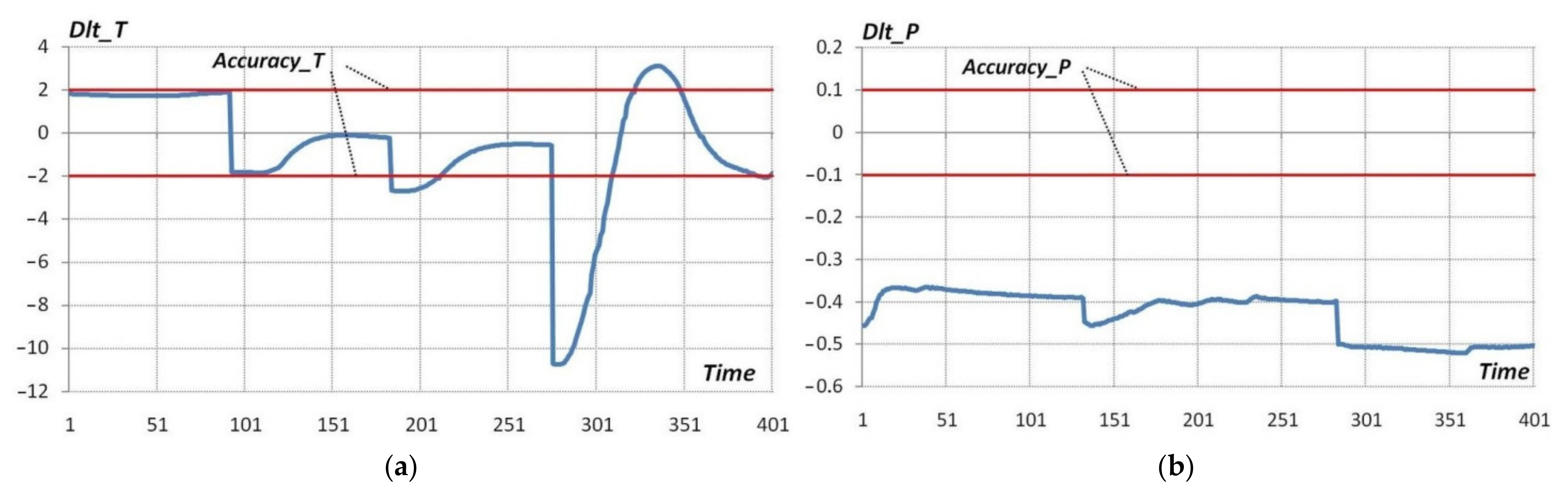
Figure 5a) leads to an increase in the temperature deviation
Dlt_T (
Figure 6a), and in order to compensate for this deviation,
rule no. 3 (position 6,
Figure 7a) generates a signal to slow the increase inthe process engine fuel flow (signal
RUD_QF,
Figure 8a).
The next change in the gas generator operating mode (position 7,
Figure 5a) leads to a sharp increase in the temperature deviation
Dlt_T, therefore, to compensate for it, initially
rule no. 4 (position 8,
Figure 7a) is triggered to rapidly increase the process engine fuel supply (signal
RUD_FF,
Figure 8a), and then
rule no. 3 (position 8,
Figure 7a) is triggered to slowly increase the process engine fuel supply (signal
RUD_QF,
Figure 8a). Since the temperature changes very quickly, the temperature control is accompanied by a small overshoot, to compensate for which,
rule no. 1 (position 9,
Figure 7a) generates a signal to reduce the process engine fuel flow (signal
RUD_QB,
Figure 8a).
To achieve the regulation goals, the fuzzy controller turns the regulated working fluid bypassing into the “closed” state (
Figure 8b). The value of the working fluid bypassing into the atmosphere cannot be increased until the operating point is near the lower limit of sensitivity (
Figure 5b). After the operating point rises from the lower limit (position 10,
Figure 5b),
rule no. 21 (position 11,
Figure 7b) generates a signal to increase the working fluid bypass (signal
BV_Open,
Figure 8b). It should also be noted that the controller does not allow for adjusting the pressure depending on the current position of the operating point.
4.2. Analysis of the Controller Action near of the Gas Generator “Maximum”Mode
Figure 9,
Figure 10,
Figure 11 and
Figure 12 show the graphs of changes in the main parameters of the logic controller and the test complex near the gas generator “Maximum” mode.
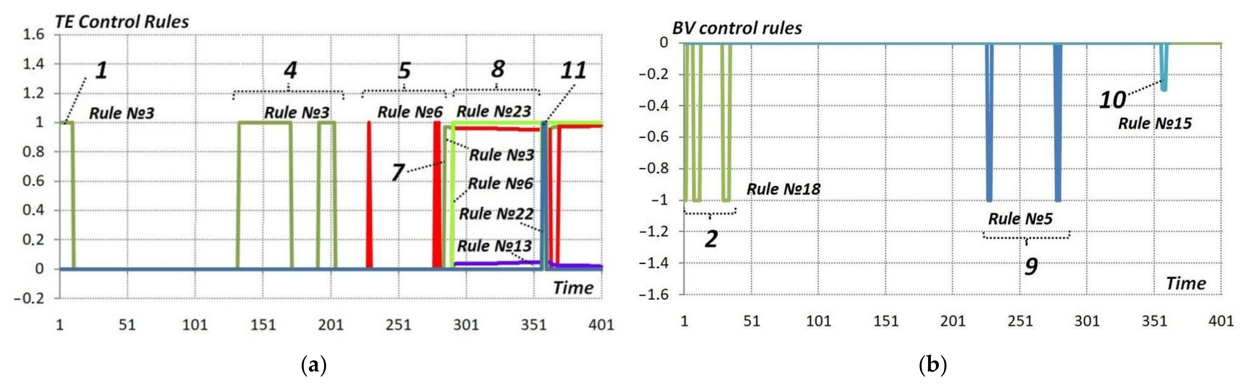
At the beginning, the temperature deviation
Dlt_T exceeds the specified control accuracy
Accuracy_T (
Figure 9a).To increase the temperature,
rule no. 3 (position 1,
Figure 11a) generates a signal to slow the increase in the process engine operating mode (signal
RUD_QF,
Figure 12a). The value of the pressure deviation
Dlt_P does not fall within the limits of the specified control accuracy
Accuracy_P (
Figure 10b) and the operating point position (
Figure 9b), thereby allowing
rule no. 18 (position 2,
Figure 11b) to generate several signals to close off the regulated working fluid bypass (signal
BV_Close,
Figure 12b) to the pressure regulation. It should be noted that the controller, apart from this small section, no longer allows pressure regulation.
Changing the gas generator operating mode (position 3,
Figure 9a) leads to temperature deviation increase
Dlt_T (
Figure 10a), and in order to compensate for this deviation,
rule no. 3 (position 4,
Figure 11a) sequential generates an array of signals to slowly increase the process engine operation mode (signal
RUD_QF,
Figure 12a).
To achieve the regulation goals, the fuzzy controller turns the regulated working fluid bypass into the “closed” state (
Figure 12b). Therefore, when the operating point crosses the lower regulation limit (
Figure 9b),
rule no. 6 (position 5,
Figure 11a) is triggered and signals were generated to increase the process engine operating mode (signal
RUD_QF,
Figure 12a).
A further change in the gas generator operating mode (position 6,
Figure 9a) leads to a sharp temperature deviation
Dlt_T (
Figure 10a), and in order to compensate for which,
rule no. 3 (position 7,
Figure 11a) generates signals to slow the increase inthe process engine operation mode (signal
RUD_QF,
Figure 12a). Furthermore, when the operating point crosses the control system control limit (
Figure 9b),
rules nos. 6, 13, and
23 (position 8,
Figure 11a) are triggered simultaneously, and sequential also generate an array of signals to slow the increase in the process engine operating mode (signal
RUD_QF,
Figure 12a). Since the position of the working point continues to decrease, and the regulated working fluid bypass has not yet reached the “closed” position,
rule no. 5 (position 9,
Figure 12b) is triggered and signals are generated to close the regulated working fluid bypass (signal
BV_Close,
Figure 12b).
Despite all the actions taken by the controller, the operating point drops below the critical regulation limit (
Figure 9b), and at the same time,
rule no. 15 (position 10,
Figure 12b) is triggered to close the regulated working fluid bypass (signal
BV_Close,
Figure 12b) and
rule no. 22 (position 11,
Figure 12a) is triggered to rapidly increase the process engine operating mode (signal
RUD_FF,
Figure 12a).
The test cyclogram was deliberately scheduled in such a way that the controlled system behavior to the extent possible exhibited the most varied factors caused by the physics of the ongoing processes. At the same time, the test complex fully exhibited the properties of a multi-variable, nonlinear, and non-stationary system. As shown by a series of simulated tests, the fuzzy controller provided a predictable and safe simulation of the gas-dynamic parameters of the working fluid. In cases of contradiction between the regulation objectives, the controller found a compromise solution with unconditional keeping of the process engine stall margins.
A further continuation of the study is the verification of the developed algorithms during field tests in a recommendatory (supervisory) mode on a specialized test complex for researching a gas generator of an advanced engine under the conditions of UEC-Aviadvigatel JSC (Russia).


 ,
, 