Article

Research on the Lightweight Design of an Aircraft Support Based on Lattice-Filled Structures

Institute of Systems Engineering, China Academy of Engineering Physics, Mianyang 621900, China
*
Author to whom correspondence should be addressed.
Mathematics 2022, 10(23), 4576; https://doi.org/10.3390/math10234576
Submission received: 7 October 2022 / Revised: 18 November 2022 / Accepted: 21 November 2022 / Published: 2 December 2022
(This article belongs to the Special Issue Numerical Analysis and Optimization: Methods and Applications)

Abstract

:
This work studied the lightweight design of an aircraft support based on lattice-filled structures. Different from the traditional design process of lattice-filled structures, this work combined several approaches, including topology optimization, homogenization analysis, and Non-Uniform Rational B-splines (NURBS) surface modeling, to reduce the structural weight more effectively. The theories and implementations involved in the design process are introduced in this work. The new lattice-filled design of the aircraft support component reduced the weight by 40% compared with the original value, and its additive manufacturability was verified. Finally, the structural responses of the lattice-filled design from both a detailed model and homogenization model were determined and compared, considering both the static responses and dynamic characteristics. The results revealed that the homogenization method efficiently and accurately obtained the structural displacements and natural frequencies of the complex lattice-filled design. This indicates that the homogenization method can effectively reduce the calculation burden of the design process of lattice-filled structures, which opens a new channel for the structural optimizations of lattice-filled structures.

1. Introduction

Weight is one of the important indicators of the structural designs of aircraft components. To the authors’ knowledge, if the structural weight of an aircraft is reduced 1%, the total weight of the aircraft decreases by 3–5%. At the same time, the weight reduction can also expand the flight range of the aircraft. Therefore, almost all components of an aircraft are required to reduce weight. However, under traditional solid structural designs, the structural lightweight has reached a bottleneck. Recently, with the development of additive manufacturing, more attention has been paid to filled structures because of their advantages, such as high specific stiffness, high thermal resistance, and high damping [1,2,3,4].
In various forms of filled structures, the lattice-filled structure has undergone widespread research because of its good designability [5,6,7,8]. The lattice material first proposed by Evans and Ashby et al. [5] was a periodic structured material composed of rods. Ashby [7] compared and analyzed the modulus characteristics of lattice materials and foam materials and concluded that the stiffness of lattice materials was much higher than that of foam materials. Kooistra [8] et al. compared and analyzed the yield strength of lattice materials, honeycomb materials, and foam materials when the matrix material was aluminum and found that the strength of the lattice materials was significantly higher than that of foam materials, and in the case of low density, lattice materials also had certain advantages over honeycomb materials. In recent years, the research scope of lattice-filled structures has rapidly expanded. Yan et al. [9] conducted a bird strike test and numerical simulation of a curved plate filled with an FCC single cell, proving the engineering application potential of the filled structure. Liu et al. [10] studied a kriging-assisted topology optimization method for the design of functionally graded cellular structures (FGCS). Sayyad and Avhad [11] used a new higher order shear and normal deformation theory to calculate the static and free vibration analysis of simply supported FGM sandwich shells. Due to space limitation, recent studies on lattice-filled structures can be found in the literature [12,13,14].
With the help of topology optimization, the weight of lattice-filled structures can be further reduced [15,16,17,18]. Topology optimization is an effective method to find the distribution of a material in a structure under certain external loads and boundary constraints. Among the topology optimization methods [19,20,21,22], the SIMP (Solid Isotropic Material with Penalization) method has the advantage of good realizability [19]. Therefore, we selected the SIMP method to carry out our research. In this work, topology optimization was adopted to obtain the optimized structural design of the macro structure of the lattice-filled structure, while the traditional design process of the lattice-filled structure often does not change the original macro structure design.
The structural numerical analysis of lattice-filled structures by the detailed finite element model is very time consuming. Homogenization analysis is an effective way to overcome this problem. In the homogenization model, the lattice structure is replaced with a simple solid model. The material parameters of the solid domain are calculated from the selected lattice structure. In this way, the DOFs (degrees of freedom) of the analysis model for lattice-filled structures are greatly decreased. Until now, many homogenization approaches have been proposed [23,24,25,26]. Among them, the NIAH (Novel numerical Implementation of Asymptotic Homogenization) approach [26,27] is relatively convenient for implementing, since it only needs to perform several finite element analyses. The NIAH approach [28,29] is a newly proposed homogenization approach, which is not only convenient to execute but can also deal with the homogenization analysis of various kinds of lattice cells, while it is relatively difficult in theory. We selected these two methods to verify the effectiveness of homogenization analysis for complex lattice-filled structures.
The above-mentioned approaches such as lattice materials, topology optimization, and homogenization analysis, have been widely studied in recent years. However, there are few studies on the structural lightweight design involving all of these approaches. This is because these approaches are relatively difficult to implement. If the design problem is carried out strictly according to the theoretical requirements of these approaches, the design process will be unapplicable. For example, for lattice-filled structures with skins, it is difficult to simultaneously design the skin and lattice core in topology optimization. Therefore, the integration of these methods requires a reasonable simplification of each method to facilitate the implementation of the entire design process.
Although the lattice-filled structure has a broad application prospect in the lightweight design of aircraft, its design approaches and implementation ability still lack research. In this study, the homogenization approach, NURBS surface modelling, and topology optimization method were combined to obtain a lightweight design for an aircraft support component. In order to make the design process executable, several technologies were used with simplification. The obtained lightweight design was fabricated using the laser selective melting additive manufacturing process. Finally, the results of the detailed analysis model and the homogenization model for the lattice-filled structures were compared and discussed.
The remainder of this paper is as follows. Section 2 introduces the design problem and initial design. Section 3 describes the involved approaches and design process of the lattice-filled structure. Next, Section 4 compares the structural responses from the detailed model and homogenization model. Finally, the conclusion is given.

2. Design Problem

The considered aircraft’s support is shown in Figure 1, which is used to transfer loads between two parts. The space between the upper flange and the bottom flange is the designable space. This kind of structure exists widely in aircraft; therefore, its lightweight design has been widely studied. After years of improvement, this support adopts the design of a thin-wall structure with several holes. Such structures are very common in topology optimization results. This means that the initial design has been well designed to be lightweight. The initial design of studied support is made of aluminum alloy material, and its weight is 1.60 kg.
The considered component bears two load cases, i.e., the axial overload (Y-axis positive direction, 70 g) and the transverse overload (X-axis positive direction, 60 g). The upper flange connects a 20 kg device, which contributes the main part of the inertial load for the support. In the structural analysis, the device is considered to be a concentrated mass placed in the center of the upper flange.
Based on engineering experience, the structure is designed to meet the following requirements: (1) The maximum deformation should not be greater than the initial design; (2) The static strength under the overload condition should not be higher than the allowable stress of the used base material; (3) The fundamental frequency of the structure should not be lower than the limit value. Figure 2 shows the static structural responses of the initial design. In the axial overload case, the maximum Vonmises stress is about 430 MPa, and the maximum value is 2.09 mm, and in the transverse overload case, the maximum Vonmises stress is about 129 MPa, and the maximum displacement is about 0.24 mm. The initial design’s fundamental frequency is 1040 Hz.

3. Design Process and Implementation of Lattice-Filled Structures

This section first introduces the theories involved in the design process and then introduces the implementations of the design process of the lattice-filled support.

3.1. Design Process and Corresponding Theories

3.1.1. Design Process

In this study, the design process which is given in Figure 3 of the lattice-filled structure is as follows:
(1)
Finite element model modeling: model the design domain, specify the types and parameters of the filled lattice, calculate the equivalent material parameters of the specified lattice, mesh the design domain, define the material parameters as the calculated equivalent parameters, define boundary conditions, etc.;
(2)
Topology optimization: define the objective function, design the variables and constraints of the topology optimization formulation, carry out the topology optimization problem;
(3)
Geometric modeling of topology optimized results: choose several control nodes and the surface of the optimized design, build NURBS surfaces surrounding the topology optimized designs, modify the locations of control nodes, add bolt holes;
(4)
Lattice filling: define the filling parameters and filling domain, uniformly fill the lattices in the filling domain;
(5)
Structural response verification: perform structural analysis; if the performance was not satisfactory, modify the local geometric model or return to (1) to modify the filling parameters.

3.1.2. Finite Element Model Modeling

Before topology optimization, the design space needs to be defined. To improve the effectiveness of topology optimization, the design space is always defined as large as possible [30]. In this work, based on the original design and space constraints of the considered component, an envelope model of the original structure was established and adopted as the design space for topology optimization. The envelope model also has the advantage of the ease of the hexahedral mesh.
Next, the analysis model of topological optimization needs to be developed according to the selected topological optimization method. For topology optimization aimed at obtaining lattice-filled structures, the multiscale topology optimization methods are mostly widely used, which simultaneous optimize the structural designs of the macro structure design and lattice design. These methods require the building of two analysis models, i.e., the macro analysis model and micro analysis model. The multiscale topology optimization has good potential for the structural design of lattice-filled structures, but it requires multi-scale analysis and multi-scale topology optimization formulation, which will be difficult when applying this to some topology optimization problems.
In order to make the optimization process of the lattice-filled structure convenient to implement, this study simplifies the optimization formulation of multiscale topological optimization. In the simplified method, the lattice design is determined before topology optimization, that is, the lattice configuration and parameters remain unchanged in topology optimization. Therefore, in topology optimization, only the macro structural design is optimized. Similar to the multiscale topology optimization method, the analysis model in topology optimization is also a homogenization model, which uses the equivalent material parameters of the chosen lattice as the material parameters. Although the ability of the simplified method to change the lattice-filled design is not as good as the multiscale topology optimization method, it has better adaptability, as it can easily use the existing methods for various optimization problems.
On the other hand, in this work, the considered component bears inertia forces with design-dependent loads. The realization of the load-related topology optimization problem is relatively difficult because of the difficulty of sensitivity analysis. Meanwhile, both the static response and dynamic characteristics are involved in the topology optimization formulation, which makes the optimization formulation relatively complex, as a nonlinear constraint is required to be involved in the topology optimization formulation. For these reasons, this work uses the simplified method to carried out the topology optimization of the lattice-filled structure.
The equivalent material parameters of the lattice structure can be obtained by several approaches. For some lattices with simple designs, for example, BCC lattice or FCC lattice, the equivalent material parameters can be obtained by analytical solutions. However, when the lattice design is complex or has strong anisotropy, homogenization methods are necessary to calculate the equivalent material parameters. Among various homogenization methods, the NIAH (Novel numerical Implementation of Asymptotic Homogenization) approach has the advantage of ease of implementation, as it only needs to perform several linear static analyses.
The NIAH approach is based on perturbation expansion theory. It can significantly reduce the programming workload and greatly improve efficiency through the rich modeling technology and element library of commercial finite element software. With the NIAH approach [28], the equivalent stiffness E i j k l H is obtained by
E i j k l H = 1 | Y | ( χ 0 ( i j ) χ ( i j ) ) T ( f 0 ( i j ) f ( i j ) )
where χ 0 ( i j ) is the displacement field corresponding to the unit strain field, χ ( i j ) is the corresponding characteristic displacement field, f 0 ( i j ) is the initial load vector corresponding to the initial strain, f ( i j ) is the characteristic load vector corresponding to the characteristic strain, and T is the notation for the transpose. The detailed implementation of the NIAH method can be found in the literature [28].

3.1.3. Topology Optimization

In this work, the SIMP method was used to carry out the topology optimization. The optimization problem is described as the maximization of the stiffness of the lattice-filled structure under the mass constraint and frequency constraint. The formulation is defined as follows: take the artificial densities of elements as the design variables, the structural volume fraction, and the fundamental frequency greater than the initial design fundamental frequency as the constraints, and the structural stiffness maximization under both axial and transverse overloads as the objective function. The optimization formulation can be defined as follows:
Find ρ = [ ρ 1 , ρ 2 , ρ i ] T R i = 1 , 2 , , N min C ( x ) = l = 1 2 U l T K U l s . t . { K U = F j = 1 N ρ j v j V f 1 ( ρ ) f 0 0 < ρ min ρ e ρ max 1
where ρ is the relative density, C(ρ) is the weighted sum of the compliances of two overload cases, N is the number of elements, K is the global stiffness matrix, U is the structural displacement vector, F is the load vector, vj is the volume of the j-th element, V* is the value of the effective volume constraint of the structure, f1(ρ) is the fundamental frequency of the structure, f* is the fundamental frequency of the initial design, which is equal to 995 Hz, ρmin and ρmax are the upper and lower limits for the design variable values, and T is the notation for the transpose. In this work, the objective function is the weighted compliance of the structure in the over-load cases.
Note that compared with the requirements of the design problems in Section 2, the topological optimization formulations do not include the stress constraints. This is because topology optimization with stress constraints is difficult to achieve, and the high-precision stress of the lattice-filled structure is also difficult to obtain. Therefore, in this work, the stress constraint is not included in the topology optimization formulation but is verified by the strength analysis of the optimized structure. If the stress exceeds the limit, we need to change the lattice design or parameter and perform the optimization process again or make local adjustment of the structural design.

3.1.4. Geometric Modeling of the Topology Optimized Results

Topological optimization can obtain a better structural design, but it often leads to too complex a structural design to form a 3D geometric model for subsequent design processes. As a result, early topological optimization methods were only used to obtain heuristic designs. In recent years, many researchers have tried to devise new topology optimization methods that can form 3D geometric models directly from the topology optimization results. However, these methods are still in the theoretical research stage, and several problems need to be solved for actual structures. At present, a relatively mature way of processing topology optimization results is to use the Non-Uniform Rational B-splines (NURBS) method to construct geometric models from topology optimization results. Although the method still requires some work, it is much more efficient than the classical sketch-based modeling method. At the same time, the NURBS surface has a good design ability, which provides great freedom for subsequent local design adjustments. Currently, the technology can be implemented through commercial CAD software such as Inspire and Rhino, as well as open-source CAD software such as FreeCAD, as shown in Figure 4.

3.1.5. Lattice Filling

Lattice filling methods can be divided into three categories [31]: uniform filling, form-dependent filling, and random filling. Uniform filling is the most widely used filling method. In the uniform filling method, all lattice cells in the lattice-filled model are the same as each other, which is beneficial to homogenization analysis and geometrical modeling. At present, this uniform filling method can be implemented by various software, such as Solid Works and other commercial CAD modeling software, 3-Matic and other additive manufacturing modeling software, Ansys and other commercial CAE software, and several open-source CAD software platforms. Therefore, we used the uniform lattice-filled method.

3.2. Lightweight Design of Lattice SkinFilling for the Support Structure

The initial design of the considered aircraft component is made of aluminum alloy. To reduce the local stress concentration, additional material needs to be added, which not only increases the weight of the support but also improves the difficult of the assembly and the production of parts.
The envelope space of the initial design is defined as the design domain in topology optimization. The design domain is a hollow cylinder with an inner diameter of 360 mm, an outer diameter of 400 mm, and a height of 100 mm, as shown in Figure 5. The bolted connection regions are set as non-designable domains. A 20 kg concentrated mass is placed in the center of the upper-end face of the model and are connected to the upper-end bolt holes. The displacements of the bolt holes at the bottom flange are all fixed. Both the axial and transverse overload cases are considered in topology optimization.
We chose the BCC lattice as the filling lattice, as shown in Figure 6. The BCC lattice has orthogonal isotropic mechanical characteristics and higher specific stiffness, which is suitable for the structure with multi-directional loads. The base material of the lattice uses Ti-6Al-4V alloy material, and the material parameters are density ρ = 4500 kg/m3, elastic modulus E = 110 GPa, and Poisson’s ratio v = 0.30.
For BCC single cells, the analytical formulation of the elastic modulus in each direction is as follows [32]:
{ ρ ¯ = π sin ϖ ( δ D ) 2 = 3 π ( δ D ) 2 E i j = E 0 ρ ¯ sin 4 ( ϖ ) = 3 π 9 ( δ D ) 2 E 0
where Eij is the equivalent stiffness parameter, ρ ¯ is the relative density of the lattice cells, ϖ is the angle of the single rod and the horizontal plane, δ is the diameter of the rod piece, D is the outer cell envelope dimension, and E0 is the elastic modulus of the base material manufactured for the additive.
The BCC cell contains nine nodes, eight of which are the eight corners of the cube, and the other node is the center of the cube. Its coordinates can be expressed, and then the geometric center coordinates need to be determined, as shown in Equation (4).
x 9 = 1 8 ( x 1 + x 2 + x 3 + x 4 + x 5 + x 6 + x 7 + x 8 ) , y 9 = 1 8 ( y 1 + y 2 + y 3 + y 4 + y 5 + y 6 + y 7 + y 8 ) , z 9 = 1 8 ( z 1 + z 2 + z 3 + z 4 + z 5 + z 6 + z 7 + z 8 )
Considering the additive manufacturability, the BCC cell size is set to 5 mm × 5 mm × 5 mm, and the rod diameter is set to 0.5 mm. The equivalent stiffness parameters of each direction obtained by the NIAH approach and analytical formulation are summarized in Table 1. Note that these two methods both obtain the parameters required by the anisotropic elastic material model.
The results show that differences in the stiffness coefficients of the different directions of the BCC lattice are very small, which shows good isotropic characteristics of BCC lattices. In addition, the equivalent stiffness coefficients of different approaches exhibited few differences. Note that only a few lattices with a simple structure can be used to analytically calculate the equivalent stiffness parameters, while the homogenization approach can be applied to various types of lattices.
Based on the topology optimization formulation given in Equation (3), the topology optimization is carried out using the Altair Optistruct. Figure 7 shows the optimized results from topology optimization. Note that in this study, the structural periodicity constraint that is one of Optistruct’s characteristic function is activated; thus, the obtained topology optimization results have good periodicity characteristics, which greatly simplifies the subsequent geometric modeling of the optimized results.
By comparing the topology optimized design with the initial design, we found that the topology optimized design is a truss-like structure, and most material are distributed to directly connect the upper and lower bolt hole, thus achieving more effective load transfer efficiency.
Using the NURBS surface to rebuild the geometrical model of topology optimization results requires a large amount of work. However, due to the good periodicity of the topology optimization results, the required modeling part is only 1/16 of the support structure. Therefore, the workload of optimized design modeling is greatly reduced.
In the modeling process, firstly, several points are selected as the control points of the NURBS surface, and then NURBS surfaces are built to surround the optimized topology design. After that, we need to adjust the position of each control point to make the geometric model smoother. Finally, several holes are dug to ensure the installation space. The geometrical model of the optimized topology design is shown in Figure 8, which is built by software Solidthinking.
After completing the geometric modeling, we need to determine the skin thickness and uniformly fill the BCC lattice cells to build the lattice-filled structure. In this work, the skin thickness is set to 0.8 mm, and the BCC lattice’s size is set to 5 mm × 5 mm × 5 mm.
The geometric model of the filling space after topological optimization is complex, and compared with the size of the filled cells, the filling space is not large enough to strictly meet the requirement of the number of lattice cells of the homogenization approach. However, in order to meet the requirements of the homogenization approach, the cell size should be very small, while in order to meet the manufacturing requirements, the rod diameter of the lattice needs to be larger than 0.5 mm. This will make it difficult to effectively reduce the weight of the structure. To balance these factors, the above-mentioned cell size was determined. Although it cannot strictly meet the requirements of homogenization analysis theory, it can effectively reduce the structural weight. Therefore, it is important to verify the accuracy of the structural responses of the homogenization approach for the lattice-filled structure.
Finally, the optimized lattice-filled structure weighs 0.97 kg, as shown in Figure 9, which is about 40% less than that of the initial design.

3.3. Machinability Verification

In this work, the optimized lattice-filled design was manufactured by SLM additive manufacturing. The considered aircraft component was constructed of Ti-6Al-4V alloy powder (the average spherical diameter of the powder particles was 30 μm). The process parameters mainly included the laser power, scanning rate, opening spacing, and interlayer thickness. The specific parameters are shown in Table 2. Through the controlling and printing strategy of the parameters shown in Table 2, after nondestructive tests, we confirmed that the internal defect of the load equipment support structure was in the allowable range. The final weight of the workpiece is 1.02 kg, and the physical support structure is shown in Figure 10.

4. Numerical Simulations of the Lattice-Filled Structure

For the lattice-filled structure, the FEM (Finite Element Method) model building and structural analysis of the detailed model are time-consuming. The homogenization approaches can overcome this problem. However, for irregular filled spaces, some parts barely meet the periodic requirements of homogenization approaches, so it is necessary to verify the effectiveness of the structural response based on homogenization analysis. As mentioned previously, the analytical approach and NIAH approach were considered in this study. In this section, only the NIAH approach is presented because the results of these three approaches showed little difference and the NIAH method has a wider range of applications. The accuracy of homogenization analysis has been widely examined. Various researchers showed that homogenization analysis has good accuracy for simple models, see references [23,24,25,26,27,28,29]. The Ansys Workbench was used as the platform in this section.

4.1. Numerical Simulation Model

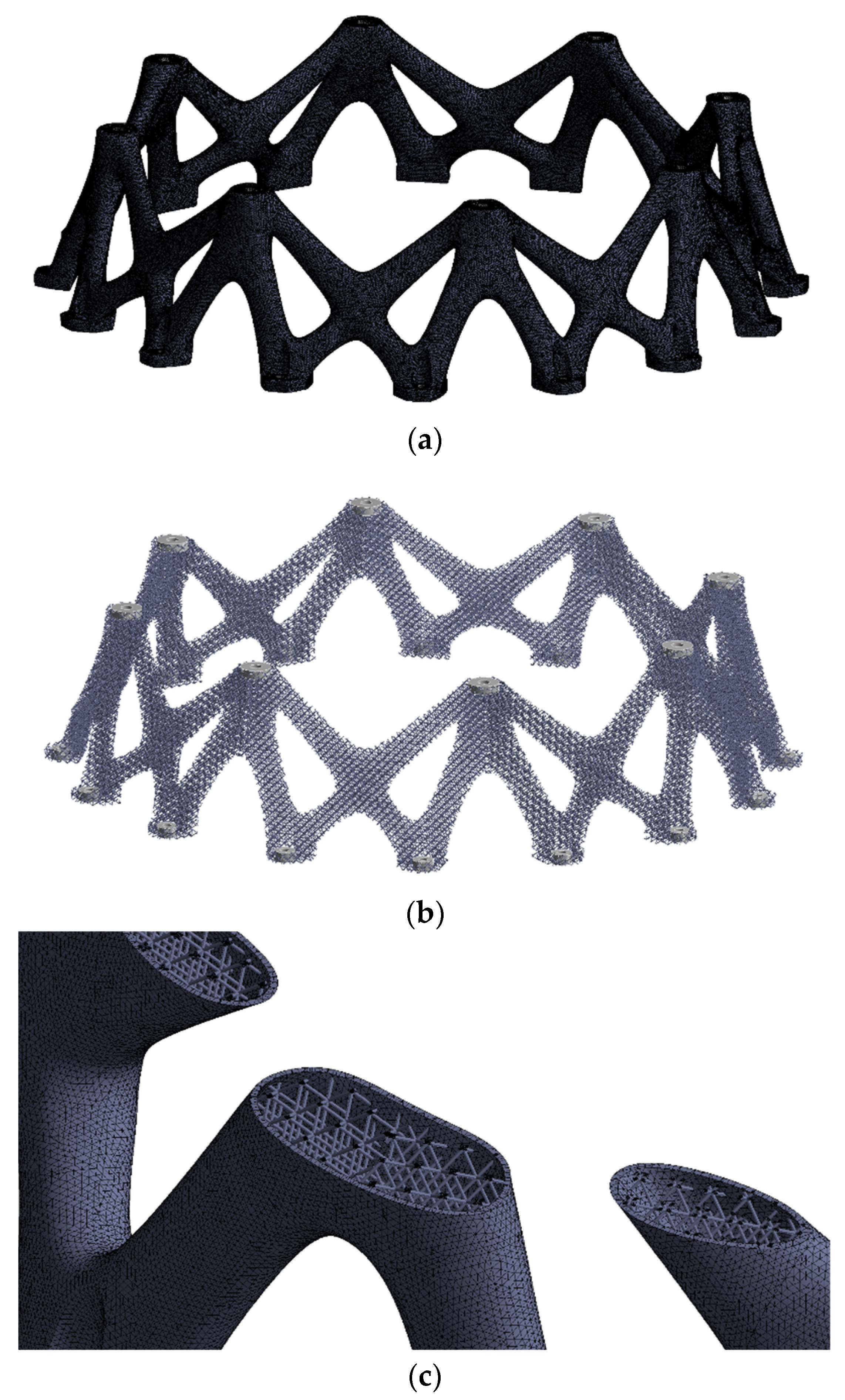
The detailed model was constructed with a mixture of solid, shell, and beam elements. The solid elements were used to model the bole holes, and the shell elements and beam elements were used to model the skin and the lattice, respectively. Although the lattice-filled design has rotational symmetry in geometry, due to computational dynamic problems, we still need to build the finite element model of the entire model, as shown in Figure 11.
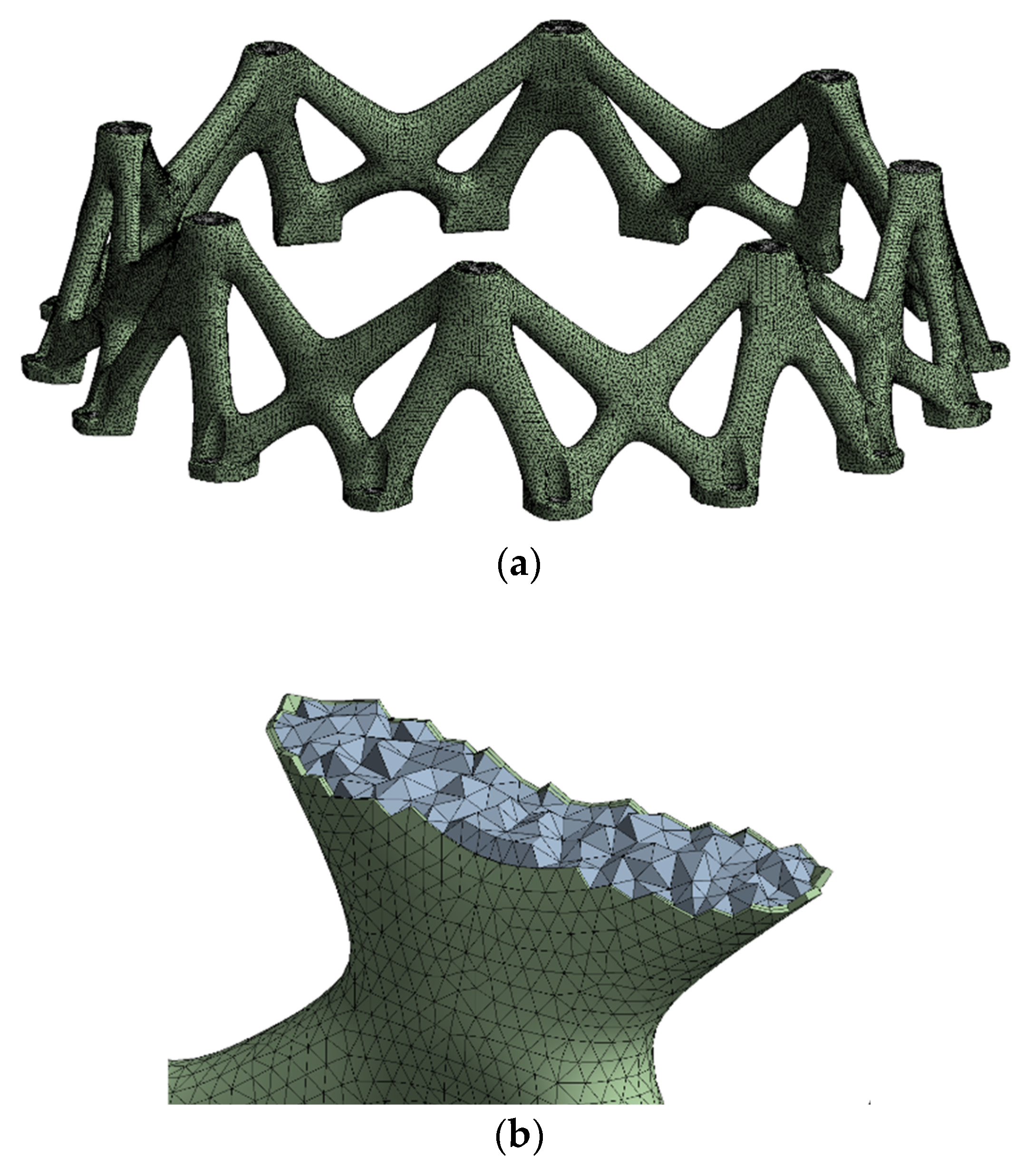
In the homogenization model, the skin is modeled by shell elements, and the lattice-filled domain and bolt holes are both modeled by solid elements, but they use different material parameters. On the other hand, since the detailed model of lattice cells is avoided, the element size of the homogenization model can be relatively large; therefore, the number of DOFs of the homogenization analysis model was much lower compared with the detailed analysis model, as shown in Figure 12.
In the detailed model, all parts used the aluminum alloy material parameters. However, in the homogenization model, the skin and bolt holes still used the aluminum alloy material parameter, but the material parameters of the homogenization domain of the lattice-filled domain used the equivalent material parameters of the specified BCC cell. The analysis model used in this section was uploaded to a website (https://github.com/SongJian6393/file1.git (accessed on 7 October 2022)).

4.2. Static Responses and Discussion

According to the analysis results of the initial design, the structural stress and displacement distributions caused by the axial overload condition (70 g) were relatively large. Therefore, in this section, the axial overload was taken as the load case to compare the differences between the detailed model and the homogenization model.
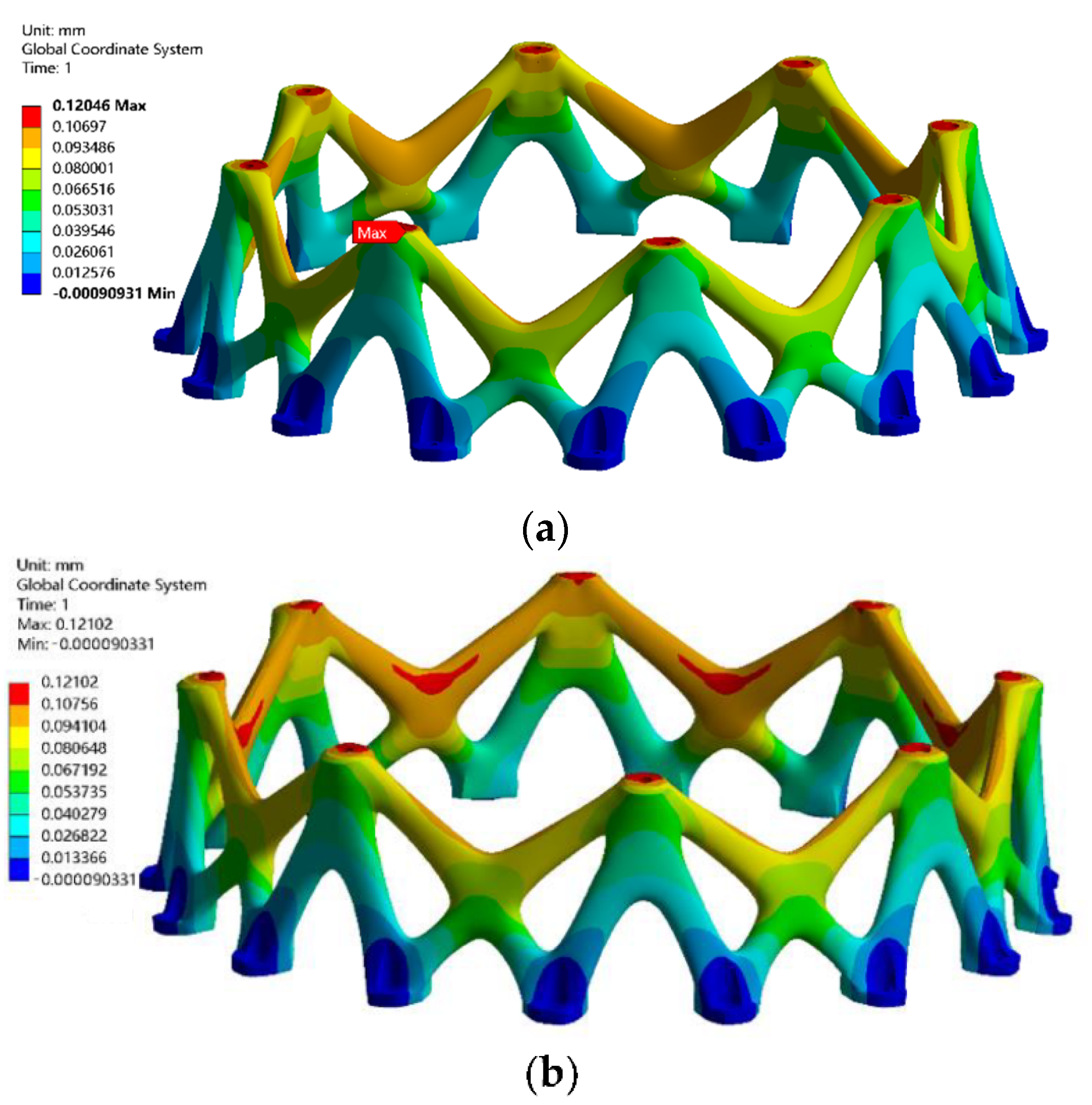
The stress and displacement analysis results based on the detailed and homogeneous analysis models are shown in Figure 13 and Figure 14, respectively. The displacement results showed that the displacement distribution and the peak responses obtained by these two models were generally consistent. In the stress results, the stress distribution was consistent with the homogeneous analysis model, but the detailed model had a higher peak stress. The results showed that the peak stress in the detailed model was about 152 MPa, while the stress level in the homogeneous analysis model was about 120 MPa. This is because the detailed analysis model had a much finer mesh, which can easily cause stress concentration.
The time-consuming value of the homogenization analysis was significantly lower than that of the detailed model because the number of DOFs of the homogenization analysis model was only about 1/4 of that of the detailed model. With the use of a personal computer (i7, 32 G), the homogenization analysis took about 15 s, while the detailed analysis model took about 48 s.
Based on a comparison of the structural responses of the lattice-filled design with the initial design, the peak stress of the lattice-filled structure was lower. The deformation level of the lattice-filled structure was also lower than that of the initial design, indicating that the former had better structural stiffness.

4.3. Dynamic Characteristics and Discussion

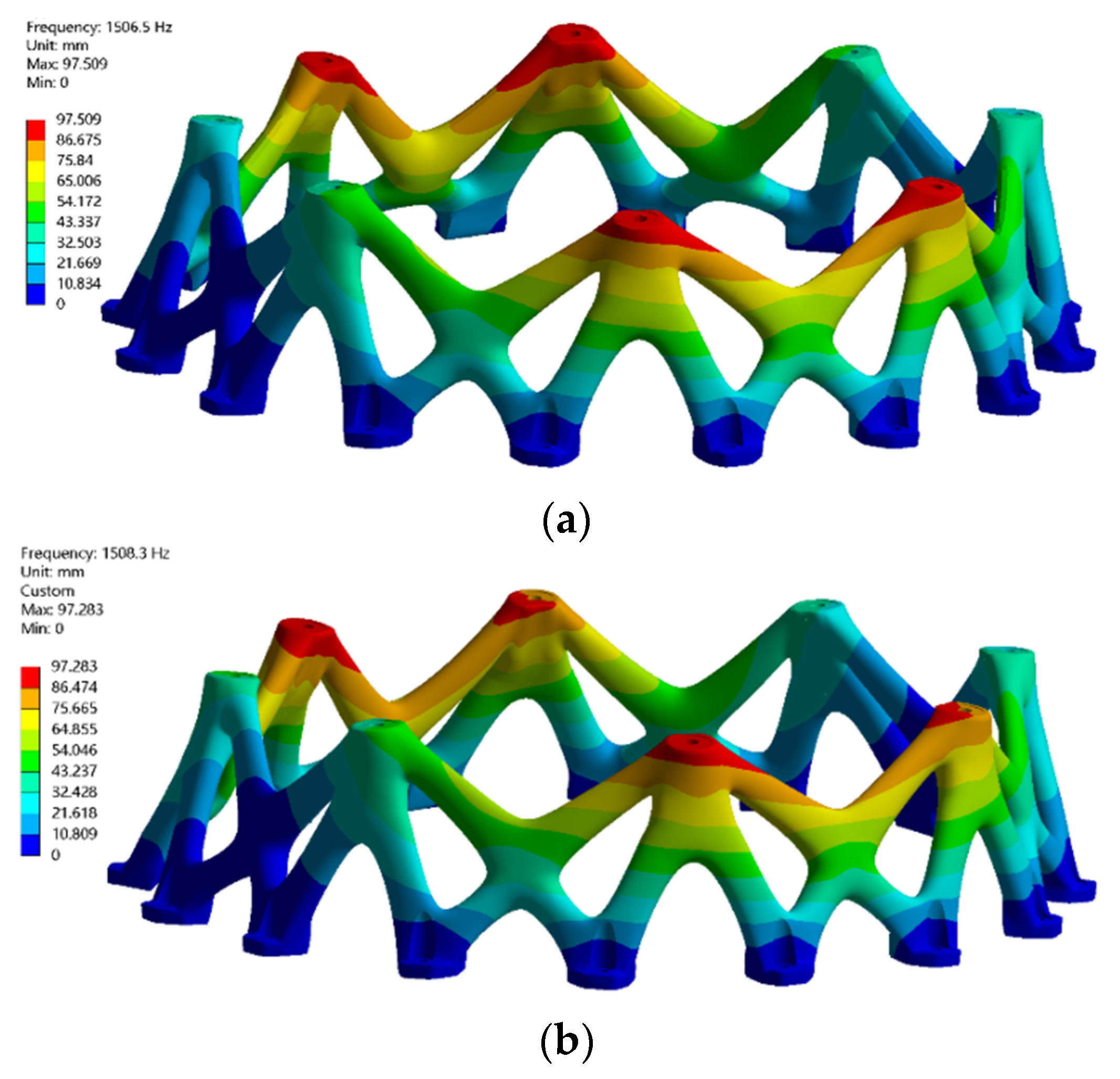
Since the support structure needs to bear and transfer dynamic loads, in this section, the mode shapes and frequencies of the detailed model and homogenization model are compared. Figure 15 shows the first mode shapes obtained from these two analyses, and Table 3 summarizes the frequencies of the first six modes.
The results showed that the difference between the results from the detailed model and the homogenization model was very small, which means that the homogenization analysis can be used to replace the detailed model for structural dynamic characteristics analysis. The results also showed that the calculation time of the homogenization analysis was significantly lower than that of the detailed model. The homogenization analysis took about 28 s, and the detailed analysis took about 353 s.
The fundamental frequency of the initial design was 1040 Hz. Compared with the initial design, the lattice-skin-filling design effectively improved the base frequency of the structure, from 1040 Hz to 1508 Hz, an increase of about 45%.

5. Conclusions

Taking a support structure as a typical design object, this work studied the feasibility of a lattice-filled structure for structural lightweight design and presents a design process in detail. It was found that the topology optimization and lattice-filling structure effectively improved the lightweight of structures. The new lattice-filled design reduced the weight by about 40% compared with the initial design. Further, the geometric reconstruction of the topology optimization results was carried out and filled by BCC cells. This step can be implemented with the help of a variety of commercial or open-source tools. Then, based on SLM additive manufacturing technology, the machinability of the lightweight design of the lattice skin filling was verified. Finally, the finite element model of detailed analysis and homogenization analysis was carried out and discussed, considering both the static structural responses and dynamic characteristics. The results showed that two analyses gave the same results of natural frequencies and mode shapes. However, the peak stress of the detailed model was higher than that of the homogenization model, which means that when using lattice skin to fill the structure, we should pay attention to the situation where the homogenization analysis results are not conservative enough. In general, the homogenization design can effectively improve the charge correction analysis efficiency of the covered lattice skin-filled structure, which is not only reflected in the time consumption of the analysis but is also reflected in the modeling of the finite element models. For machinability, if the selected lattice meets the requirements of additive manufacturing, whether the optimal design can undergo additive manufacturing depends on whether the macro structure can be printed.
In the future, the influence of different lattice configurations and parameters on the structural responses needs to be studied to explore the optimal lattice configurations and filling parameters. The development of mathematics is becoming more and more important for solving engineering problems. It is expected that researchers can find new problems worth studying through this paper.

Author Contributions

Conceptualization, Z.H. and Y.L.; methodology, Z.H.; software, Z.H.; validation, X.H. and D.M.; writing—original draft preparation, Z.H.; writing—review and editing, Z.H. and Y.L.; visualization, Z.H. and Y.L. All authors have read and agreed to the published version of the manuscript.

Funding

This research received no external funding.

Institutional Review Board Statement

Not applicable.

Informed Consent Statement

Not applicable.

Data Availability Statement

The data that support the findings of this study are available from the corresponding author upon reasonable request.

Conflicts of Interest

The authors declare no conflict of interest.

References

  1. Smith, B.H.; Szyniszewski, S.; Hajjar, J.F.; Schafer, B.W.; Arwade, S.R. Steel Foam for Structures: A Review of Applications, Manufacturing and Material Properties. J. Constr. Steel Res. 2012, 71, 1–10. [Google Scholar] [CrossRef] [Green Version]
  2. He, M.; Hu, W. A study on composite honeycomb sandwich panel structure. Mater. Des. 2008, 29, 709–713. [Google Scholar] [CrossRef]
  3. Wadley, H.N.G.; Fleck, N.A.; Evans, A.G. Fabrication and structural performance of periodic cellular metal sandwich structures. Compos. Sci. Technol. 2003, 63, 2331–2343. [Google Scholar] [CrossRef]
  4. Hao, P.; Wang, B.; Li, G. Surrogate-based optimum design for stiffened shells with adaptive sampling. AIAA J. 2012, 50, 2389–2407. [Google Scholar] [CrossRef]
  5. Evans, A.G.; Hutchinsona, J.W.; Ashby, M.F. Multifunctionality of cellular metal systems. Prog. Mater. Sci. 1998, 43, 171–221. [Google Scholar] [CrossRef]
  6. Ashby, M.F.; Evans, A.; Fleck, N.A.; Gibson, L.J.; Hutchinson, J.W.; Wadley, H.N.G. Metal foams: A design guide. Appl. Mech. Rev. 2012, 23, 119. [Google Scholar]
  7. Ashby, M.F. Designing Hybrid Materials. Acta Mater. 2003, 51, 5801–5821. [Google Scholar] [CrossRef]
  8. Kooistra, G.W.; Deshpande, V.S.; Wadley, H.N.G. Compressive behavior of age hardenable tetrahedral lattice truss structures made from aluminium. Acta Mater. 2004, 52, 4229–4237. [Google Scholar] [CrossRef]
  9. Yan, J.; Zhang, C.G.; Huo, S.X.; Chai, X.H.; Liu, Z.H.; Yan, K. Experimental and numerical simulation of bird-strike performance of lattice-material-infilled curved plate. Chin. J. Aeronaut. 2021, 34, 245–257. [Google Scholar] [CrossRef]
  10. Liu, X.; Gao, L.; Xiao, M.; Zhang, Y. Kriging-assisted design of functionally graded cellular structures with smoothly-varying lattice unit cells. Comput. Methods Appl. Mech. Eng. 2022, 390, 114466. [Google Scholar] [CrossRef]
  11. Zhang, C.; Liu, J.; Yuan, Z.; Xu, S.; Zou, B.; Li, L.; Ma, Y. A novel lattice structure topology optimization method with extreme anisotropic lattice properties. J. Comput. Des. Eng. 2021, 5, 1367–1390. [Google Scholar] [CrossRef]
  12. Khalil, M.A.; Lebaal, N.; Demoly, F.; Roth, S. A design and optimization framework of variable-density lattice structures for additive manufacturing. Mech. Adv. Mater. Struct. 2021, 3, 1–15. [Google Scholar] [CrossRef]
  13. Abate, K.M.; Nazir, A.; Yeh, Y.-P.; Chen, J.-E.; Jeng, J.-Y. Design, optimization, and validation of mechanical properties of different cellular structures for biomedical application. Int. J. Adv. Manuf. Technol. 2019, 106, 1253–1265. [Google Scholar] [CrossRef]
  14. Bian, Y.; Yang, F.; Li, P.; Wang, P.; Li, W.; Fan, H. Energy absorption properties of macro triclinic lattice structures with twin boundaries inspired by microstructure of feldspar twinning crystals. Compos. Struct. 2021, 271, 114103. [Google Scholar] [CrossRef]
  15. Liu, L.; Yan, J.; Cheng, G. Optimum structure with homogeneous optimum truss-like material. Comput. Struct. 2008, 86, 1417–1425. [Google Scholar] [CrossRef]
  16. Niu, B.; Yan, J.; Cheng, G. Optimum structure with homogeneous optimum cellular material for maximum fundamental frequency. Struct. Multidiscip. Optim. 2009, 39, 115–132. [Google Scholar] [CrossRef]
  17. Pizzolato, A.; Sharma, A.; Maute, K.; Sciacovelli, A.; Verda, V. Multi-scale topology optimization of multi-material structures with controllable geometric complexity—Applications to heat transfer problems. Comput. Methods Appl. Mech. Eng. 2019, 357, 112552. [Google Scholar] [CrossRef]
  18. Yan, J.; Yang, S.; Duan, Z.; Yang, C. Minimum compliance optimization of a thermoelastic lattice structure with size-coupled effects. J. Therm. Stresses 2015, 38, 338–357. [Google Scholar] [CrossRef]
  19. Sigmund, O. A 99 line topology optimization code written in MATLAB. Struct. Multidiscip. Optim. 2001, 21, 120–127. [Google Scholar] [CrossRef]
  20. Yang, X.Y.; Xie, Y.M.; Steven, G.P.; Querin, O.M. Bidirectional evolutionary method for stiffness optimization. AIAA J. 1999, 37, 1483–1488. [Google Scholar] [CrossRef]
  21. Wang, M.; Zhou, S. Synthesis of shape and topology of multi-material structures with a phase-field method. J. Comput. Aided Mater. Des. 2004, 11, 117–138. [Google Scholar] [CrossRef]
  22. Zhang, W.; Yuan, J.; Zhang, J.; Guo, X. A new topology optimization approach based on Moving Morphable Components (MMC) and the ersatz material model. Struct. Multidisc. Optim. 2016, 53, 1243–1260. [Google Scholar] [CrossRef]
  23. Kalamkarov, A.L.; Kolpakov, A.G. Analysis, Design, and Optimization of Composite Structures, 2nd ed.; Prentice Hall: Hoboken, NJ, USA, 1997. [Google Scholar]
  24. Zhang, H.W.; Liu, Y.; Zhang, S.; Tao, J.; Wu, J.K.; Chen, B.S. Extended multiscale finite element method: Its basis and applications for mechanical analysis of heterogeneous materials. Comput. Mech. 2014, 53, 659–685. [Google Scholar] [CrossRef]
  25. Yan, J.; Huo, S.; Yu, T.; Zhang, C.; Chai, X.; Hu, D.; Yan, K. Multiscale analysis for 3D lattice structures based on parallel computing. Int. J. Numer. Methods Eng. 2021, 122, 6756–6776. [Google Scholar] [CrossRef]
  26. Cheng, G.D.; Cai, Y.W.; Xu, L. Novel implementation of homogenization method to predict effective properties of periodic materials. Acta Mech. Sin. 2013, 29, 550–556. [Google Scholar] [CrossRef]
  27. Cai, Y.; Xu, L.; Cheng, G.D. Novel numerical implementation of asymptotic homogenization method for periodic plate structures. Int. J. Solids Struct. 2014, 51, 284–292. [Google Scholar] [CrossRef] [Green Version]
  28. Xu, L.; Cheng, G.D. Shear stiffness prediction of reissner-mindlin plates with periodic microstructures. Mech. Adv. Mater. Struct. 2017, 24, 271–286. [Google Scholar] [CrossRef]
  29. Wang, B.; Tian, K.; Hao, P.; Zheng, Y.; Ma, Y.; Wang, J. Numerical-based smeared stiffener method for global buckling analysis of grid-stiffened composite cylindrical shells. Compos. Struct. 2016, 15, 807–815. [Google Scholar] [CrossRef]
  30. Yan, K.; Wang, Y.Y.; Pan, Y.; Sun, G.; Chen, J.; Cai, X.H.; Cheng, G.D. Topology Optimization of Simplified Convective Heat Transfer problems using the Finite Volume Method. Sci. China. Technol. Sc. 2022, 4, 1–34. [Google Scholar]
  31. Tang, Y.; Dong, G.; Zhao, Y.F. A hybrid geometric modeling method for lattice structures fabricated by additive manufacturing. Int. J. Adv. Manuf. Technol. 2019, 102, 4011–4030. [Google Scholar] [CrossRef]
  32. Zhang, X.; Zhou, H.; Shi, W.; Zeng, F.; Zeng, H.; Chen, G. Vibration Tests of 3D Printed Satellite Structure Made of Lattice Sandwich Panels. AIAA J. 2018, 56, 4213–4217. [Google Scholar] [CrossRef]
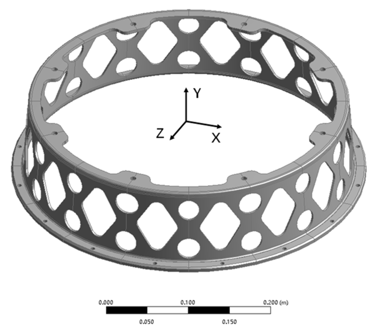
Figure 1. The considered aircraft support, which is a thin-walled structure with several holes and is made of aluminum alloy, weighing 1.60 kg.
Mathematics 10 04576 g001
Figure 2. Structural responses of the initial design: (a) Displacement distribution in the axial overload case; (b) Displacement distribution in the transverse overload case; (c) Vonmises stress distribution in the axial overload case; (d) Vonmises stress distribution in the transverse overload case.
Mathematics 10 04576 g002aMathematics 10 04576 g002b
Figure 3. Flowchart of the design process of the lattice-filled structure.
Mathematics 10 04576 g003
Figure 4. NURBS surface reconstruction topology optimization design.
Mathematics 10 04576 g004
Figure 5. Analysis model in topology optimization; the yellow solid domain is the design domain, and the blue round hole domains are the non-design domains.
Mathematics 10 04576 g005
Figure 6. Schematic diagram of the body-centered cubic cell.
Mathematics 10 04576 g006
Figure 7. Topology optimization results of the support structure.
Mathematics 10 04576 g007
Figure 8. Geomatical model of the optimized topology design.
Mathematics 10 04576 g008
Figure 9. Lattice-filled design of the aircraft support (inner diameter of 360 mm, outer diameter of 400 mm, height of 100 mm): (a) overall view; (b) partial cross-section view.
Mathematics 10 04576 g009
Figure 10. The products of the support structure based on additive manufacturing.
Mathematics 10 04576 g010
Figure 11. Detailed FEM model with a total of about 310,000 nodes: (a) entire model; (b) beam elements of lattice and solid elements of bolt holes; (c) internal view.
Mathematics 10 04576 g011
Figure 12. Homogenization analysis model with a total of 85,000 nodes: (a) full model; (b) internal model.
Mathematics 10 04576 g012
Figure 13. VonMises stress distribution: (a) detailed model analysis results; (b) homogeneous model analysis results.
Mathematics 10 04576 g013
Figure 14. Displacement distribution: (a) The detailed model; (b) The homogenization model.
Mathematics 10 04576 g014
Figure 15. Mode shape of the first mode: (a) The detailed model; (b) The homogenization model.
Mathematics 10 04576 g015
Table 1. The equivalent material’s stiffness coefficients of the specified BCC lattice from different methods.
MethodStiffness Coefficients (MPa)
D11D22D33D12D13D23D44D55D66
Analytical formulation435435435435435435435435435
NIAH431431431419419419425425425
Table 2. SLM Process Parameters.
Laser Power/WScan Rate/mmOpen Space/mmThickness/μm
12035000.10–0.1930
Table 3. Comparison frequencies of the first six modes of the detailed model and the homogenization model.
ModeDetailed ModelHomogenization ModelRelative Error
11508.31506.50.1%
21508.61506.60.1%
31522.91517.10.3%
41526.81527.70.0%
51527.91527.70.0%
61665.61658.90.4%
Publisher’s Note: MDPI stays neutral with regard to jurisdictional claims in published maps and institutional affiliations.