Article

Sizing and Design of a PV-Wind-Fuel Cell Storage System Integrated into a Grid Considering the Uncertainty of Load Demand Using the Marine Predators Algorithm

by
Fayza S. Mahmoud
1,
Ashraf M. Abdelhamid
2,*,
Ameena Al Sumaiti
3,*,
Abou-Hashema M. El-Sayed
1 and
Ahmed A. Zaki Diab
1,*
1
Electrical Engineering Department, Faculty of Engineering, Minia University, Minia 61111, Egypt
2
Communications and Electronics Engineering Department, College of Engineering, Umm Al-Qura University, Al-Lith Branch, Makkah 24382, Saudi Arabia
3
Advanced Power and Energy Center, Electrical Engineering and Computer Science, Khalifa University, Abu Dhabi 127788, United Arab Emirates
*
Authors to whom correspondence should be addressed.
Mathematics 2022, 10(19), 3708; https://doi.org/10.3390/math10193708
Submission received: 22 July 2022 / Revised: 20 September 2022 / Accepted: 26 September 2022 / Published: 10 October 2022

Abstract

:
In this paper, the utility grid is integrated with hybrid photovoltaic (PV)/wind/fuel cells to overcome the unavailability of the grid and the single implementation of renewable energy. The main purpose of this study is smart management of hydrogen storage tanks and power exchange between the hybrid renewable energy and the grid to minimize the total cost of the hybrid system and load uncertainties. PV and wind act as the main renewable energy sources, whereas fuel cells act as auxiliary sources designed to compensate for power variations and to ensure continuous power flow to the load. The grid is considered a backup system that works when hybrid renewable energy and fuel cells are unavailable. In this study, the optimal size of the components of the hybrid energy system is introduced using two methods: the marine predators’ algorithm (MPA) and the seagull optimization algorithm (SOA). The optimal sizing problem is also run accounting for the uncertainty in load demand. The results obtained from the proposed optimization are given with and without uncertainty in load demand. The simulation results of the hybrid system without uncertainty demonstrate the superiority of the MPA compared with SOA. However, in the case of load uncertainty, the simulation results (the uncertainty) are given using the MPA optimization technique with +5%, +10%, and +15% uncertainty in load, which showed that the net present cost and purchase energy are increased with uncertainty.
MSC:
49K35; 49K45; 93E20

1. Introduction

The use of fossil fuels causes tremendous increases in environmental pollution and harmful emissions [1]. In 2020, the pollution in the world decreased by 5.9% compared to that in 2019 because of the corona virus pandemic, which significantly reduced the world energy consumption [2]. Consequently, the world started paying more attention to hybrid renewable energy systems (HRES), the definition of which includes single or multiple sources of renewable energy (RE). For example, wind, solar, fuel cells (FCs), hydropower, biomass, and biogas energy are being used to increase the efficiency of the system and improve the power supply reliability. Moreover, FCs are used as a backup storage system with efficiencies higher than those of batteries [3,4,5,6,7]. Most HRESs are used either standalone or are combined with an electrical grid. Standalone systems are used to cover consumption in isolated regions [8]. Meanwhile, combined systems are used in regions with uncertain atmospheric conditions to overcome the unreliability of the utility grid [9,10,11,12,13,14,15,16,17].
Nowadays, many studies explain and evaluate the modeling, optimal sizing, and simulation of hybrid systems including RE with FCs and those connected to a grid using a proposed optimization technique for enhancing the reliability as well as minimizing the energy cost of the system [17,18,19,20,21,22]. Several optimization algorithms for attaining the optimal solution to HRES have been presented in the literature review. Particle swarm optimization (PSO) was combined with branch bound algorithm (BBA) for the optimal sizing of HRESs in connection with a grid under uncertainty [23]. The optimal solution for a photovoltaic (PV)/wind/diesel was shown through the deployment of the strength Pareto evolutionary algorithm for reducing the CO2 emissions and obtaining the minimum total cost of a hybrid system [24]. In another study, the genetic algorithm (GA) method was applied for the optimum design of a solar (PV)/wind, with a storage battery bank for minimizing the loss of power supply probability (LPSP) and the system total cost [25]. Also, the optimal design for a PV/wind turbine/battery hybrid system was implemented using gray wolf optimization (GWO) to obtain the minimum total cost per annum and improve system reliability [26]. This research presents the various hybrid energy system configurations to meet the power requirements of the electric vehicle charging station (EVCS) situated in the northwest region of Delhi, India. Moreover, modified salp swarm algorithm (MSSA) is used to minimize the total net present cost and levelized cost of energy [27].
The aim of Ref. [28] is to find the sizing of the HRES components taking into consideration uncertainties of PV, wind systems and load demand through the use of an improved crow search algorithm (ICSA). The results of the system proved the superiority of the ICSA in comparison with PSO and crow search algorithm. Also, the simulation results showed that the cost of the system is increased and that its reliability is improved. In a previous study [29], the uncertainty of wind energy systems is determined by Monte Carlo simulation according to the wind speed variation. Due to the uncertainty of renewable energies, a probability undetermined scenario-based sizing model (PUSS model) is applied for optimal sizing of HRES comprising wind generators, solar photovoltaic panels, energy-storage devices, and diesel generators [30]. The effect of the uncertainty on load demand was also studied in another piece of research [31]. Also, a method to estimate the PV power uncertainty is explained in a previous study [32].
The main reason for using new optimization methods in power systems is that optimization techniques many times are complex, might require high computational time, and/or recognized for less convergence speed, being trapped in local optima, and inaccurate results. Because of the fluctuation and unpredictability of renewable power generation and the continuous variations in the load demand, hybrid systems should be implemented considering generation and load uncertainty to achieve precise costs and reliability. Many advanced approaches for estimating uncertainty have been presented in previous studies, including distance-based analysis, robust optimization (RO), probabilistic method (PM), feasibility method, information gap decision theory (IGDT), and hybrid possibility probability method (HPP) [33,34]. One paper analyzed the methods for delivering electricity in remote locations and mentioned the benefits and drawbacks of each solution [35]. The critical issue in such research was the desalination of water in remote areas at low cost and without any pollution, and desalination units were supplied by renewable energy sources (wind/solar/FCs) for improving the performance of the system and its efficiency [36]. More studies have demonstrated the optimization of grid integration with hybrid renewable energy, with FCs as backup storage systems. A combination of either PV/FC or PV/FC/grid has been analyzed to feed the load with low-cost energy in remote areas. Results indicate that grid-integrated HRES are more economic and perform better than off-grid systems [37]. The seagull optimization technique has been aaplied to get the optimal design of the grid-connected renewable energy system, composed of PV panels, wind turbines, inverter, rectifier, electrolyzer, and fuel cell for minimizing the energy cost [17].
Over the last few years, FCs started gaining more attention as storage systems and played important roles in HRES for delivering continuous power to load [38]. FCs have many benefits in comparison with batteries; for instance, they have no harmful emissions, high efficiencies, and low temperatures [39]. In this paper, if the power of solar PV and wind energy is larger than the load consumption, the excess power feeds an electrolyzer system for producing hydrogen, which is kept in tanks for later use to supply FCs to generate electricity. When the level of the hydrogen tank gets to the maximum (top), the power extracted from the PVs and wind system is sold to the grid. However, if the power generated from PVs, wind, and FCs does not meet the load demand, the shortage in power is compensated from the main grid. Also, for the optimal sizing, the numbers of PV arrays, wind turbines, hydrogen tanks mass, the rated power of electrolyzers, inverters, and FCs should be optimized. This is in addition to optimizing the power between the RES and the utility, which is determined by two elements (selling and purchasing coefficients) [40]. The most critical issues in this study are the modeling of the hybrid system components to satisfy the load requirements, attaining the maximum system reliability and attaining the minimum generated energy cost. Because of the complexity of the optimization of the hybrid system, new techniques were discovered to solve optimization problems, such as the marine predator’s algorithm (MPA) and the seagull optimization algorithm (SOA). Moreover, the proposed optimization techniques have been comprehensively compared in terms of the best solution. The south of Egypt has been used as a case study to confirm the feasibility of the proposed techniques by calculating the hourly wind speed, solar radiation, and temperature.

Installation Description

Figure 1 displays a diagram of an RES connected to a grid consisting of solar PV cells, wind energy, a utility grid, bidirectional converters, FCs, electrolyzers, hydrogen tanks, and a certain load. FCs act as backup storage systems, whereas solar and wind energy work as the primary source. The power grid serves as a secondary (auxiliary) source to meet the required power.

2. Mathematical Modeling

This section focuses on the mathematical model of the hybrid system components, and electrical power exchange (selling and purchasing) is explained. Then, hydrogen management, objective constraints, and power management strategies are analyzed to reach the optimal configuration of every component in the hybrid system.
The lifetimes of wind energy, solar PV cells, and FCs are considered as 20, 25, and 15 years, respectively, and the lifetime of the system is taken as 25 years. According to the lifetime of the case of study, two methods are proposed for minimizing the total energy cost and sizing of the components of the hybrid system.

2.1. Modeling PV System

The PV output power of PV modules is proportional to solar radiation, temperature, and geographical locations [41]. The amount of power can be calculated as follows [40]:
P pv t = P r pv n pv η pv η wire I t 1000 1 λ T T am + NOCT 20 800 I am t 25
where n pv , P r _ pv , and P pv t are the number of PV cells, the maximum power of the PV cells, and the output power produced from solar PV cell, respectively. η wire and ηpv are the wiring efficiency and the efficiency of the PV cells, respectively. λ T is the temperature coefficient of the solar PV modules, and Iam(t) is the ambient of solar radiation.
The total output power produced from solar PV cells is calculated as follows:
P tot _ pv t = N pv × P pv t

2.2. Modeling Wind Turbine System

The wind speed and hub height characteristics are the most important factors in generating output power from wind turbines, which can be determined using the following equation [42,43]:
V 2 = V 1 H 2 H 1 β WT
where V 1 and V 2   are the wind speed at a reference point at ( H 1 ) and hub height ( H 2 ), and β WT indicts to the friction coefficient, and its value is 0.143 [44].
The following equation is applied to estimate the output power produced from the wind turbines (WTs) [44].
P w t = n w η w P r _ w ( V 2 ( t ) V 2 c in ) ( V 2 r V 2 c in ) V c _ in < V ( t ) < V r n w η w P w r V r < V ( t ) < V c _ off O V ( t ) < V c _ in   or   V ( t ) < V c _ off
where P w t is the output power produced from WTs, n w ,   η w ,   and   P r _ w are the number of WTs, the WTs efficiency, and the maximum power of the WTs, respectively.
The total output power produced by a group of wind turbines is calculated as follows:
P tot _ w = N w ×   P w t

2.3. Modeling Grid System

The HRES can be integrated into the grid through a common coupling point because the utility grid is considered a bidirectional source that can either purchase energy from the grid when the power generation from PV, wind, and FCs cannot satisfy the required consumption, or sell energy to the grid in case the power produced from the HRES is greater than the load demand and when the hydrogen tank reaches full charge. The purchasing cost of energy from the network can be evaluated by:
C g p = £ p _ pur × t = 1 8760 P g p
where £ p _ pur is the Egyptian price for purchasing power from the exterior grid, $/kWh is 0.08 $/kWh, and P pur _ g refers to (indicates) the power bought from the electric grid.
The following equation is used to estimate the proceeds from selling power to the utility grid:
C g s = £ P sell × t = 1 8760 P g s
where C sell _ g is the proceeds from the sold power to the grid, and P   sell _ g is the selling power into the external grid. £ P _ sell is the Egyptian price (tariff rate) of selling power, which is equal to 0.2 $/kWh.

2.4. Modeling Electrolyzers

The excess energy generated from PVs and wind sources is utilized to feed the electrolyzer for the generation of hydrogen by separating water into oxygen (from the cathode side) and hydrogen (from the anode side) by passing a direct current (DC) through two electrodes (See Equation (8)) [45]. Then, the produced hydrogen is stored in tanks with high pressure [46].
Electricity +   H 2 O =   H 2 + 1 2   O 2
The power output delivered from the electrolyzer to the tank of the hydrogen is illustrated as follows [45]:
P ele H 2 t = P ren _ ele × η ele
where P ele H 2 t is the electrolyzer output power (kw), P ren _ ele is the electrolyzer input power (kw), and η ele   is the efficiency of the electrolyzer assigned a constant value.

2.5. Modeling H2 Tank

During peak periods, if the power produced from the PVs and wind sources is low, the necessary amount of hydrogen is used to feed FCs to compensate for the leakage (shortage) in the required power. The hydrogen energy at any (t) is illustrated as follows:
E H 2 t Δ t = E H 2 t t 1 + P ele H 2 t P H 2 t fc t η st _ t × Δ t
where E H 2 t Δ t and E H 2 t t 1   are the amounts of energy kept in the tank at times t and (t − 1), respectively. P H 2 t fc t is the power supplied to the FCs. η st _ t is the hydrogen tank efficiency, which is taken as 95% for all operations.
The mass of the hydrogen produced from the electrolyzes can be estimated as follows [45]:
M H 2 t Δ t = E H 2 t Δ t HHV H 2
where HHV H 2 is the higher heating value of the hydrogen and is set to 39.7 kWh/m2.

2.6. Modeling FC

An FC is a device employed to convert chemical energy to electrical DC energy using an electrolyzer [47,48,49], and is composed of two electrons (anode and cathode) and an electrolyte that lies in between. It has more advantages compared with batteries such as its simplicity, low maintenance, and high efficiency, and it also causes no pollution (i.e., is a green energy source) [47].
The generated power from FC can be determined by Equation (12) as follows:
P fc inv =   P H 2 t fc × η fc  
where P H 2 t fc is the FC input power, and η fc   is the efficiency of the FCs.

2.7. Modeling DC/AC Converter

The power produced from the PVs and wind turbines is needed for a conversion of DC power to alternating current (AC) power as the consumed power by the loads is AC. The output power generated from the inverter is calculated through Equation (13):
P inv AC = P fc inv × P ren inv   η inv  
where P fc inv is the FC output power, P ren inv is the output power produced from RES, and η inv is the the inverter’s efficiency assumed constant (90%).

2.8. Economical Evaluation of the Optimization Parameters

2.8.1. Loss of Power Supply Probability

The loss of power supply probability (LPSP) is a criterion used for evaluating the reliability of the proposed energy system, the LPSP is constrained to not increase to about ε LP [43]. The below equation is used for calculating the value of the LPSP.
LPSP = t = 1 8760 ( P ld t P w t P pv t P fc t ) t = 1 8760 P ld t

2.8.2. Fluctuation of the Power Sold to the Grid

The fluctuation rate ( F g s ) of the power supplied to the grid can be estimated as follows:
F g s = P g s _ max P g s _ min Δ t
where P g s _ max and P g s _ min are considered the maximum and minimum surplus power delivered to the main utility, respectively. The value of the fluctuation rate should not exceed a predefined value ( ε fl ) [50].

2.8.3. Cost of Energy (COE)

The total annual cost of the hybrid system is equal to the overall cost of each component in the proposed system (PV, wind turbine, FCs, electrolyzer, H2 tank, converters, and cost of purchasing and selling of energy to the grid).
C an _ total = C an _ cap + C an _ rep + C an _ o & m + C pen + C g p C g s
where   C an _ total is the overall annual cost in the hybrid system, C an _ cap , C an _ rep , and C an _ o & m   are the annual capital cost for every component in the system, the annual replacement cost, and annual cost for operation and maintenance cost for each component in the system, respectively. C g p and C g s represent the annual cost of purchasing from and selling energy to the grid, respectively.
Annual capital cost: It can be calculated as follows:
C an _ cap = C an _ cap _ pv + C an _ cap _ wt + C an _ cap _ fc +   C an _ cap _ ele + C an _ cap _ H 2 t + C an _ cap _ con
The annual capital cost of each component in the overall system is illustrated as shown in (18):
C ann _ cap _ wt = C cap _ wt × CRF ( i , n wt ) C ann _ cap _ fc = C cap _ fc × CRF ( i , n fc ) C ann _ cap _ ele = C cap _ ele × CRF ( i , n ele ) C an _ cap _ H 2 = C cap _ H 2 t × CRF ( i , n H 2 t ) C an _ cap _ pv = C cap _ pv × CRF ( i , n pv ) C an _ cap _ con = C cap _ con × CRF ( i , n con )
where C cap _ wt ,   C cap _ fc , C cap _ ele ,   C cap _ H 2 t , C cap _ pv , and C cap _ con are the initial capital costs of the wind turbine module, FC, hydrogen tanks, electrolyzers, PV module, and converter, respectively.   n wt , n fc , n ele , n H 2 t , n pv , and n con are the lifetime of the WTs, FCs, hydrogen tanks, electrolyzers, PV module, and converter, respectively. i represents the annual interest rate (%).
Capital Recovery Factor ( CRF ) is involved for converting the investment cost to the capital cost. Equation (19) is considered to determine CRF.
CRF i , n i = i 1 + i n i 1 + i n i 1
where n i is the lifespan for each subsystem.
  • Annual replacement cost: this cost appears when the lifetime of the components is shorter than the project lifetime.
C an _ rep = C rep _ i × ( N n i ) N
  • Annual operation and maintenance cost: This refers to the cost either required to operate a component of the hybrid system or used when any component needs repair.
C tot _ o & m = C an _ o & m _ pv × t pv + C an _ o & m _ wt × t wt + C an _ o & m _ fc × t fc +   C an _ o & m _ ele × t ele + C an _ o & m _ h 2 t × t h 2 t + C an _ o & m _ con × t con
where C an _ o & m _ pv ,   C an _ o & m _ wt , C an _ o & m _ fc , C an _ o & m _ ele , C an _ o & m _ h 2 t , and C an _ o & m _ con are the operation and maintenance cost of PVs, WTs, FC, hydrogen tanks, electrolyzers, and converter, respectively, whereas t pv ,   t wt ,   t fc ,   t ele ,   t h 2 t ,   and   t con are the operating hours for solar PV, WTs, FC, hydrogen tanks, electrolyzers, and converter, respectively.
  • Penalty cost: This appears when the values of the fluctuation rate and LPSP exceed the predefined value. It is evaluated as follows:
C pen =   C pen 1 × LPSP ε LP × t = 1 8760 P ld t + C pen 2 × F g s ε fl ε fl 100
where C pen 1 and C pen 2 are the penalty costs of the shortage and supply fluctuation, respectively.
  • Annual purchasing cost of the main network: tit is the cost of power purchased from the grid and calculated using Equation (6).
  • Annual cost of selling energy to the grid: it is the cost of the power sold to the electric grid and can be calculated using Equation (7).
The net present cost (NPC) of the hybrid renewable energy sources can be obtained using Equation (23):
NPC = C an _ tot CRF
The COE of the hybrid power systems is formulated using the following equation:
COE = C an _ _ tot t = 1 8760 P ld t = NPC t = 1 8760 P ld t × CRF

3. Energy Management Strategy (Operation)

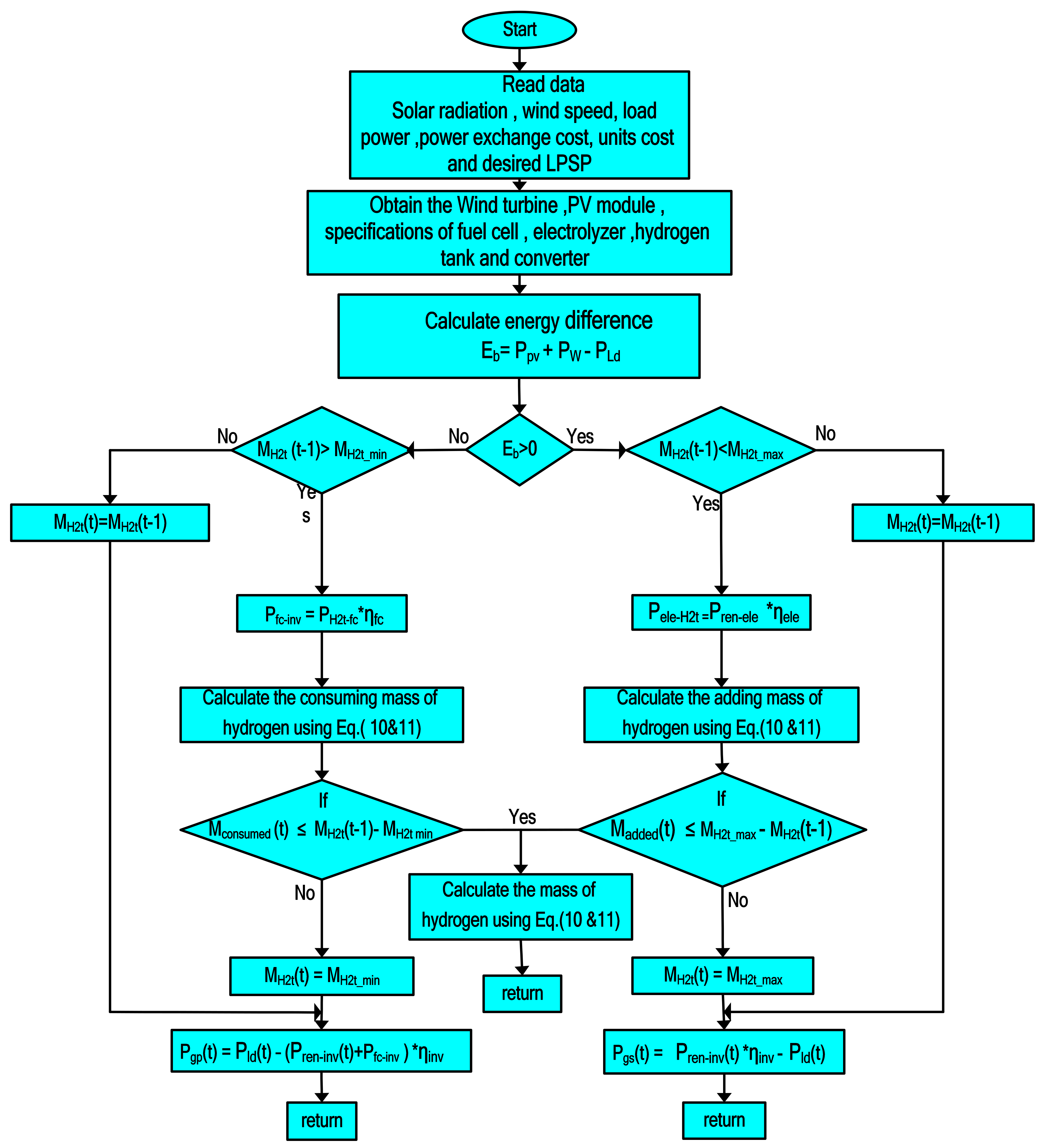
An energy management strategy is employed for controlling and managing the produced energy from the hybrid energy systems to cover the required load. The shortage in load can be satisfied by two sources: the first is the renewable energy sources, which act as the main sources, and the second is the grid as an auxiliary source. An FC is taken as a backup storage system. Moreover, it is used to determine the generated hydrogen by the electrolyzer, the power produced by the FC from hydrogen tanks, and the selling and purchasing power.
The optimization program is used to determine the energy balance ( E b ):
E b = P ren P ld  
P ren _ e = P PV + P W
In this regard, there are three cases in this study.
Case 1: E b = 0 . This case occurs when the consumption of the loads equals the generated power from RES.
Case 2: E b > 0 . When the amount renewable energy output power ( P ren ) is higher than the load requirement, the extra energy is supplied to the electrolyzers to generate hydrogen that would be stored in high-pressure tanks, and the surplus power would be sold to the grid.
Case 3: E b < 0 . During peak periods, if the generated power from RES cannot satisfy the load requirement, the unmet energy is covered by the FC, which is supplied from the hydrogen tanks. If the amount of stored hydrogen in H 2 tanks is not sufficient to feed the FC, the energy needed to cover the unmet load demand is bought from the electric grid. Figure 2 describes this strategy for the hybrid energy system.

3.1. Constraints

The components of the power system have to operate under certain constraints according to the following equation to balance the power generated from the system at any time.
P ld = P pv + P w + P fc ±   P g
The generated power must be constrained to avoid charging problems from the electrolyzer and discharging by the FC device.
M H 2 t _ min M H 2 t t   M H 2 t _ max
where M H 2 t _ max denotes the full capacity of the H2 tanks, and M H 2 t _ min is the minimum of the hydrogen tanks capacity.
The LPSP must be constrained for evaluating the hybrid power system reliability. LPSP ε LP , where ε LP = 5 % .

3.2. Objective Function

In this work, minimizing the COE and LPSP is considered the main objective of the hybrid system, and it can be determined as follows:
min y of   = min   j 1   COE + j 2   LPSP  

4. Optimization Techniques

In this study, optimization algorithms (SOA and MPA) are applied to design renewable energy systems for the optimal configuration of the HRES.

4.1. Seagull Optimization Algorithm (SOA)

Seagulls are sea birds which have different lengths and weights. They eat eggs, insects, earthworms, fish, and reptiles. These birds are very intelligent in searching for food. They use pieces of bread to attack and hunt fish or create rain sounds with their feet for attacking unseen (hidden) earthworms. These agents can drink both saltwater and freshwater because they have two glands on the top of the head, which are designed to dispose of the extra salt. In general, seagulls can live in colonial (groups), and they use their intelligence in migration and hunting their prey. Their migration behavior is described seagulls’ movement from one location to alternative location seasonally to obtain the most plentiful food sources [17,51].

The Mathematical Model

  • Migration (exploration)
During migration, seagulls should meet three conditions that can be described as follows:
  • Preventing collisions: collisions between other seagulls is avoided by updating their place using an additional parameter M b
P new y = M b × P initial y
where P new y and P initial y represent the new position of the candidates after preventing the collision and the seagull’s initial position, respectively. y denotes the present iteration, and M b is the motion of the agents in the searching space and can be calculated as follows:
M b = w w × y y max
where y = (0, 1………, y max ), and y max is the maximum number of iterations. w decreases linearly to 0, and the value of   M b starts at   w and ends at 0 when y max   is reached.
  • Movement to the best position: after preventing collisions with other individuals, the seagull moves toward the direction of the best search space. This can be explained as follows:
P to best y = A × P best y P initial y
where P to _ best y is the position toward the best search seagull, and P best y is the better location in the searching space at iteration y. A is a parameter to balance the local and global searches and can be calculated as follows:
A = 2 × B × B × ran
where ran represents a random element [0–1].
  • Remaining close to the best search candidate: after the seagull moves toward the best position, its position can be updated to reach the new best position.
P c best y = P new y + P to best y
where P c _ best y is the best-fit search agent.
2.
Attack of seagulls (exploitation)
During a seagull attack, a seagull can change its speed and angle of the attack toward the prey in spiral 3D motion using X, Y, and Z as an indication of their motion behavior:
X = k × cos θ
Y = k × sin θ
Z = k × θ
k = γ × e θ l
where k is the spiral radius, γ and l   are constants of the spiral movement, and θ   denotes the angle that is randomly between 0 and   2 π .
The position of seagulls can be updated through Equation (39):
P initial y = X × Y × Z × P c best y + P best y
where P initial y   keeps the best result and updates the location of other seagulls. Figure 3 Illustrate the SOA optimization algorithm.

4.2. Marine Predators Algorithm (MPA)

In this optimization technique, both predator and prey are searching agents. This is due to the fact that the prey is also looking for its food at the same time that a predator is trying to find its prey [52]. The initial solution is of uniform distribution over the searching space based on the following formula:
Y 0 = Y min + rand Y max Y min
where Y 0 is the initial value of the parameters, and Y min and Y max   are the minimum and maximum bounds on each variable. rand is a random element between 0 and 1. Then, the theory of the survival of the fittest is used to calculate the MP fitness. The fittest solution is a top MP, used to construct an elite matrix [53].
Elite = Y 1 , 1 1 Y 1 , 2 1 Y 2 , 1 1 Y 2 , 2 2 . . Y n , 1 1 . . Y 1 , d 1 . Y 2 , d 1 . . . Y n , d 1
Then, another matrix called prey is used to update the position of the predator and has the same dimensions as the elite matrix.
prey = Y 1 , 1 Y 1 , 2 Y 2 , 1 Y 2 , 2 . . Y n , 1 . . Y 1 , d . Y 2 , d . . . Y n , d
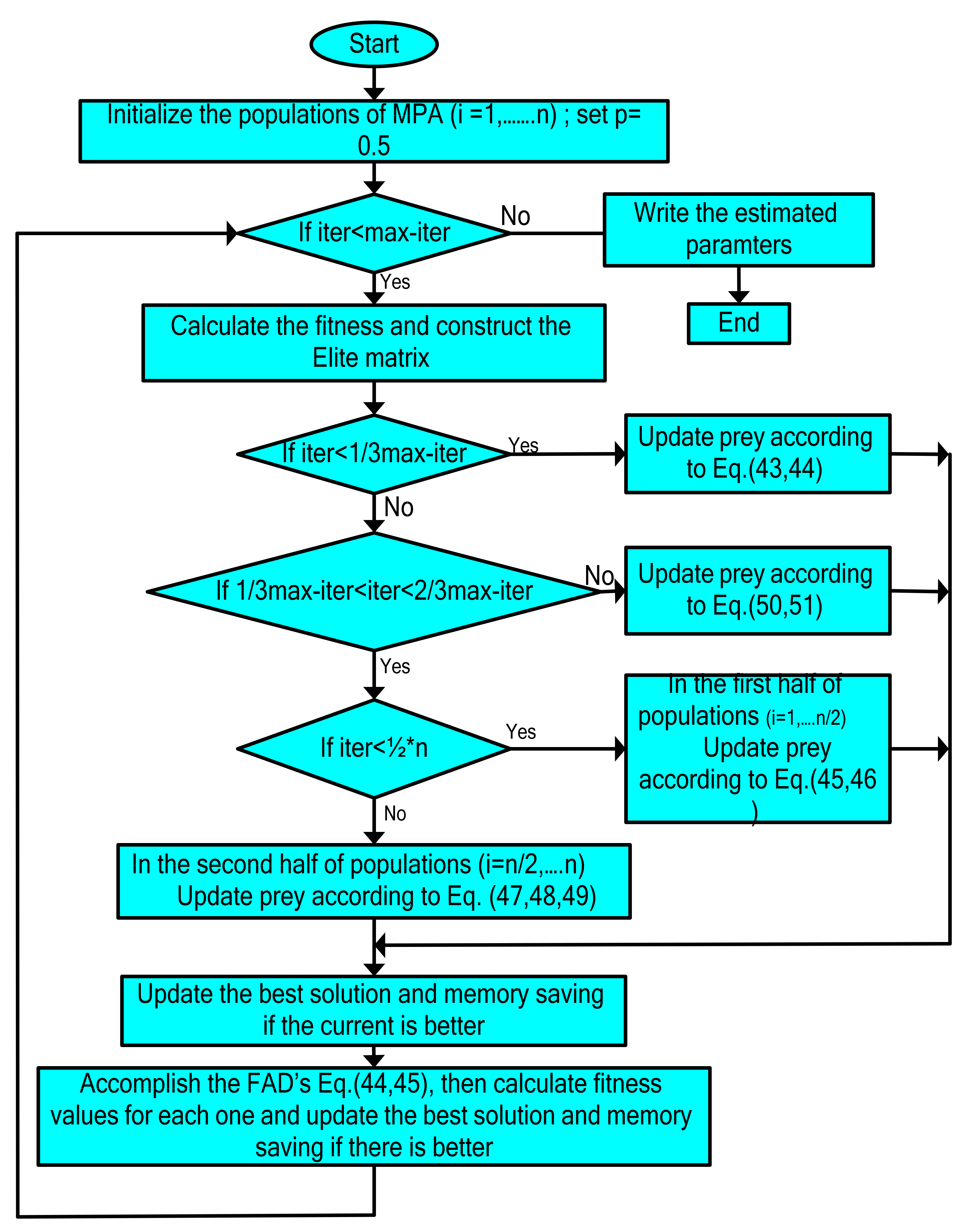
The movement of the predator and prey in MPA optimization consists of three main phases of optimization, specified by a period of iteration. In the first phase, the predator does not move at all, whereas it moves in Brownian motion in the second phase. In the third phase, it shows a Levy behavior. The MPA optimization algorithm is shown in Figure 4.

4.2.1. Exploration Phase

This phase happens in the initial iteration (one-third of iterations) of the optimization when the step size or the motion’s speed is high (V ≥ 10) for high exploring ability   iter < 1 3 max iter .
stepsize j = K B Elite j K B Prey j j = 1 , , n
Prey j = Prey j + P . K stepsize j
where iter   is the recent iteration, and   max iter is the maximum number of iterations, respectively, K B and K are vectors that contain random numbers. The first vector is based on the nominal distribution introducing Brownian motion, but the second vector is in the range of [0–1].   represents the entry wise multiplications.   P is considered a constant value (0.5).

4.2.2. Intermediate Phase

This phase happens in the unit velocity ratio (V~1), when both predator and prey move at the same pace.
1 3 max iter < iter < 2 3 max iter
The population in this phase is divided into two parts: the first half for exploration and the second for exploitation.
  • The first half of the population:
The prey is the explorer and is moving in Levy steps. The updates in prey’s position are as per the predator’s movement in Brownian motion.
stepsize j = K L Elite j K L Prey j j = 1 , , n / 2
stepsize j = K B K B Elite j Prey j j = 1 , , n / 2 , n
where K L is the Levy flight behavior.
  • The second half of the population
The predator is responsible for exploitation and moves in Brownian motion.
stepsize j = K B K B Elite j Prey j j = 1 , , n
Prey j = Elite j + P . CF stepsize j
where CF is defined as an adaptive parameter for controlling the predator’s step size and can be calculated as follows:
CF = ( 1 iter max _ iter ) 2   iter max _ iter

4.2.3. Exploitation Phase

This phase occurs in a low-velocity ratio ( V = 0.1 ) when the predator’s movement is faster compared to the prey’s movement, and this is described as follows:
iter < 2 3 max iter
stepsize j = K L K L Elite j Prey j j = 1 , , n
Prey j = Elite j + P . CF stepsize j

5. Case Study

“Marsa Alam” is located in the south east of Egypt, situated on the western coast of the Red Sea. This city covers an area of about 38,433 km2. It is positioned at latitude 25.5° N, longitude 36.7° E, and 60 m above the seawater level. The town is about 274 km south of Hurghada, 134 km south of Kosseir, and about 170 km east of the Nile Valley. Marsa Alam has a population of approximately 11,497 people.
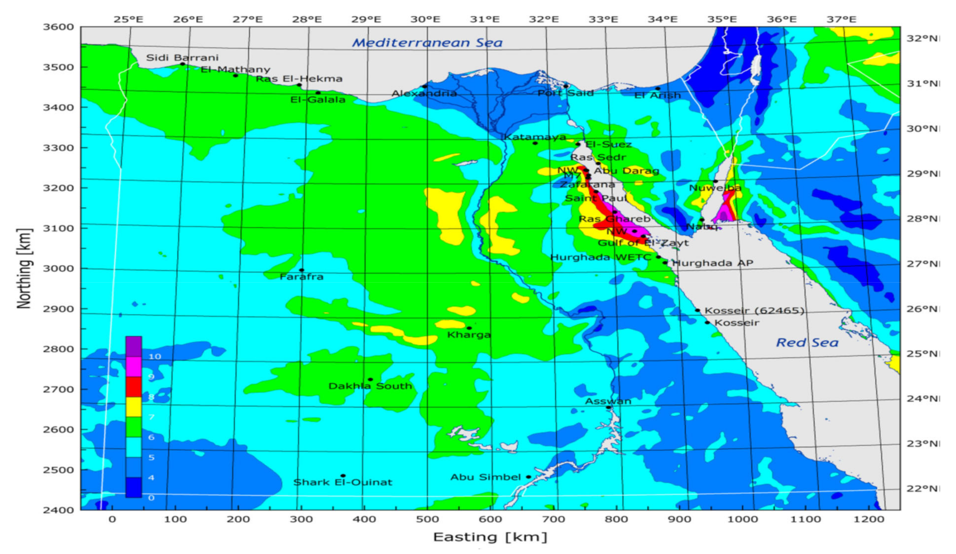
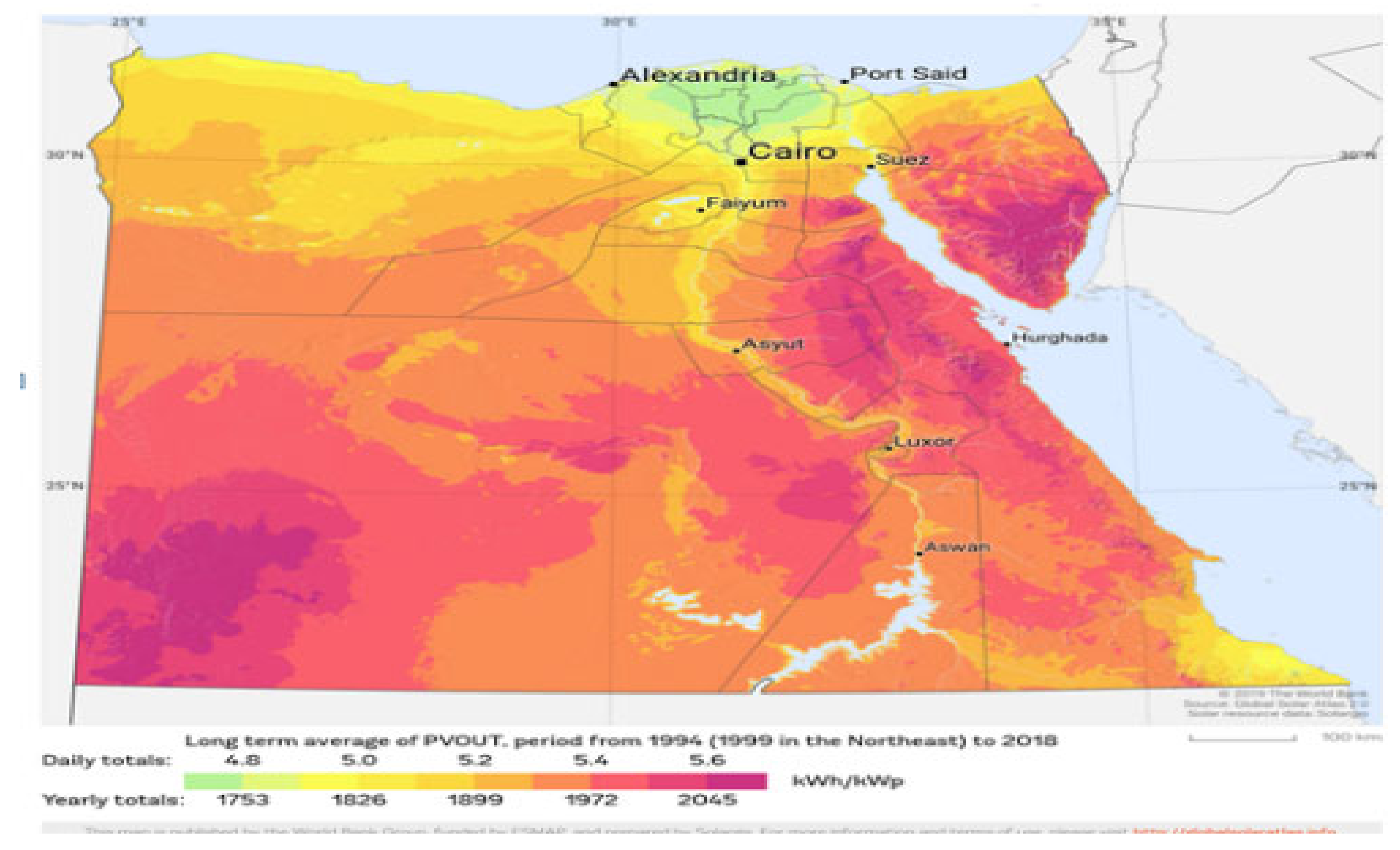
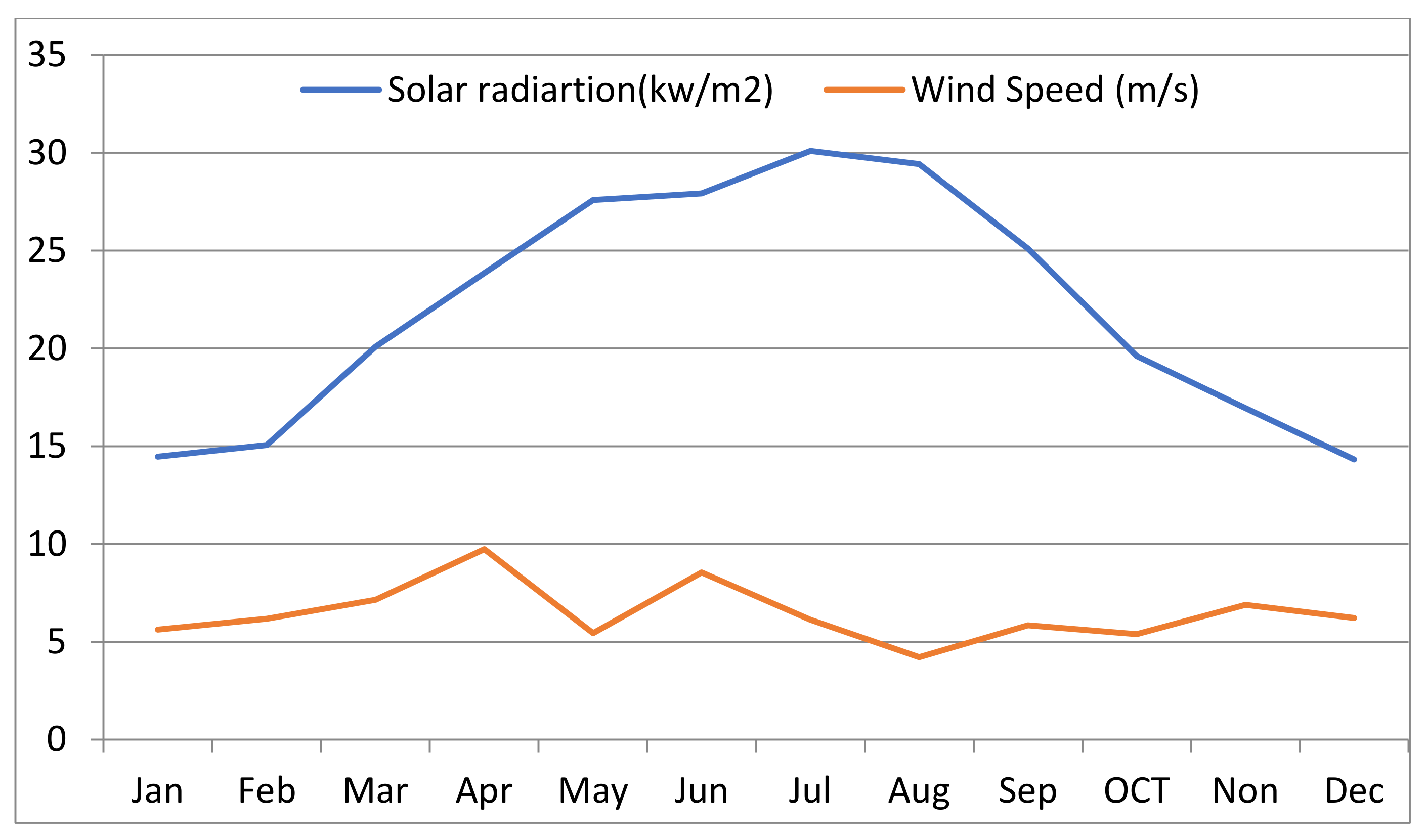
The superior renewable energy projects are concentrated in south Egypt as a result of its high solar radiation and high wind speed. Figure 5 and Figure 6 display the wind speed and the solar radiation spectra for the region (Marsa Alam). The data of the study area were obtained over one year (8760 h). As shown in Figure 7, this region promised to implement solar PV and WTs. Figure 8 shows the average annual variation of the load demand for the study area.

6. Simulation Results of the Hybrid System

In this study, the specifications of each element utilized in HRES are illustrated in Table 1. The system’s lifetime was taken as 25 years, the interest rate was taken 6%, and the lifetime of FC was taken 5 years.
The simulation results were obtained using MATLAB software program. In addition, the maximum number of iterations and the highest number of searching agents are 50 and 30, respectively.
In this paper, the optimization process is implemented without and with uncertain load to find the optimal solution for each element, such as the number of solar PVs panel, the number of WTs, the electrolyzer’s rated power, the mass of the H2 tanks, and the rated power of the FC and inverter. The economic specifications of the system components have been listed in Table 1.
Case 1: Results of the HRES without uncertain load (optimal case)
The simulation results of the proposed optimization for the two techniques are introduced in Table 2. Figure 9 illustrates the convergence curves for the PSO, SOA and MPA optimization methods, that proved the superiority of the MPA compared with SOA. As shown in Figure 9, MPA reached the optimum solution of 1.0102 after five iterations, whereas SOA reached the optimum solution of 1.0169 after three iterations. According to the results of the optimization algorithms, it is concluded that the MPA predicts the best COE of 0.3044 $/kWh, with the least NPC of 7.350895 × 10⁶ $ and LPSP of −4.883 × 10⁻¹⁸. Finally, SOA estimates 0.3115 $/kWh for the COE, which results in an NPC of 7.523017 × 10⁶ and LPSP of −9.7063 × 10⁻¹⁹, which agree with the defined value (<0.05). While the PSO has been applied for comparison purposes with one of the most conventional optimization algorithms, as expected, the results of PSO algorithm are not satisfactory when comparing with other optimization algorithms of MPA and SOA. The analyses of the results of PSO show that an increase in the NPC results in increasing the sold power to the grid and increasing renewable energy sources. The reset discussion will be focused on the MPA and SOA as their superior performance against PSO.
The comparison is clearly presented in Figure 10, in which the components of the objective function for each optimization method are presented.
The results of MPA optimization algorithms proved that the COE is minimum at the proposed location. The optimal sizing of the system is determined to be 250 PV arrays, 70 wind turbine, electrolytes with rates power of 300 kw, 150 kg for the maximum mass of H2 tanks, the FC with rated power of 100 KW and also, inverter with rated power of 150 KW.
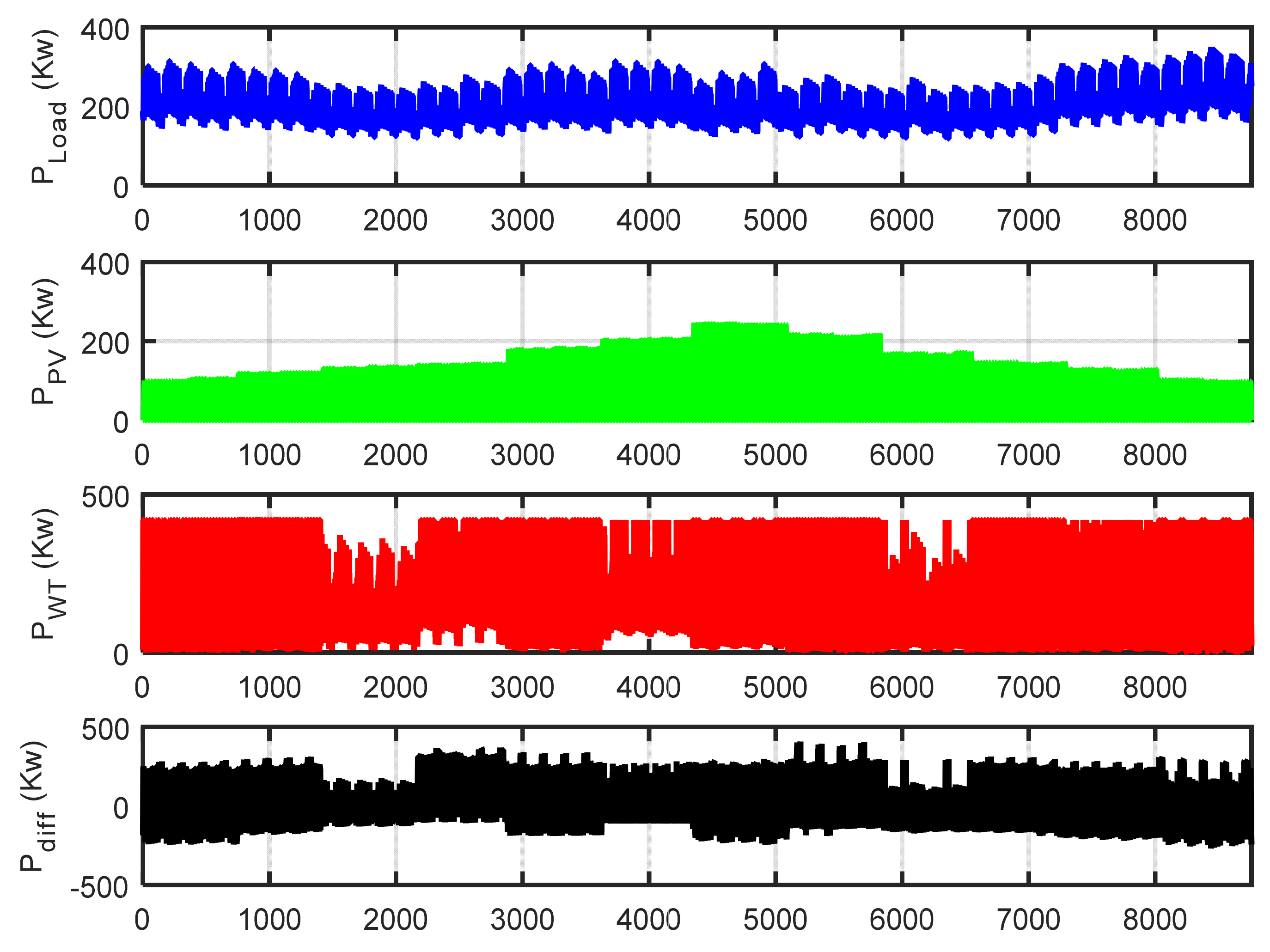
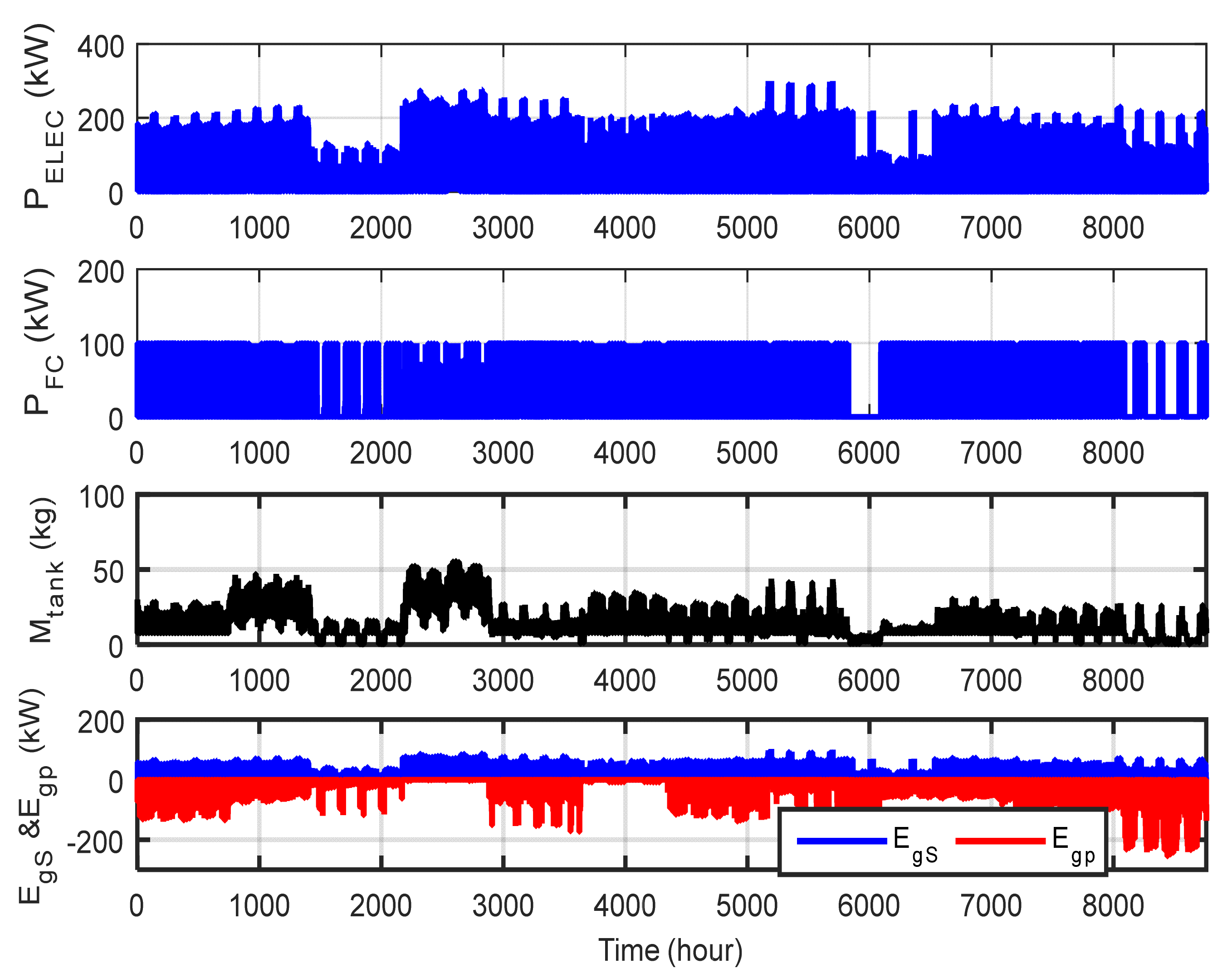
Figure 11 shows the variability in the power generation per hour for the elements of the HRES at the optimal scenario for MPA. The simulation results illustrated in this figure are the load demand ( P ld ), power produced from PV (   P pv ), power generated from the WT ( P w ), difference among the load and the overall power generated from PVs and WTs ( P diff ), rated power consumed by the electrolyzer ( P ele ), power produced by fuel cell ( P fc ), mass of the hydrogen tanks ( P H 2 t ), rated power of the inverter ( P inv ) and lastly the power exchange with the electrical network, which displays the sell and purchase power during the period of operation ( E g S   and   E g p ).
As a matter of the designed constraints, it is really hard to obtain the mandates of the optimization techniques while assuring no energy is exchanged with the external power grid. It is obviously observed that almost enough energy would be flowing to/from an exterior utility to satisfy the load.
Depending on the status of the power generation of RES, the following three cases are presented:
If the generated energy from RES and the power consumed by the load demand are equal, there is no need for any external source to satisfy the load.
If the power generation from the RES is high, the electrolyzer is used to absorb the surplus energy to produce hydrogen, and the latter is collected in its tanks. After the hydrogen tank reaches its maximum limit, the excess power is sold to the electrical grid.
During the hours of low power generation, the lack of energy is compensated by producing energy from the FC. Moreover, when the FC power generation is not sufficient to satisfy the requirements of the load, then the remaining energy demand is obtained from the exterior grid. During the hours of low power generation, the lack of energy is compensated by producing energy from the FC. Moreover, when the FC power generation is not sufficient to satisfy the requirements of the load, then the remaining energy demand is obtained from the exterior grid.
Figure 12 shows the results of the HRES for one day at the optimum case of operation using the MPA algorithm. As seen in Figure 12, at night times as well as at early hours, the power produced from PV and the wind turbine reached its minimum value; thus, the unmet load is covered by the FC. It is observed from this figure that, after 04:00 a.m., the wind speed apparently reaches its maximum value, and the output power from the WTs have increased. In this case, the electric energy over the load demand is utilized to operate the electrolyzer to produce hydrogen to be stored in tanks. The stored hydrogen is supplied to the FC for the generation of electricity to feed the load in case of low power generation, and the remaining power is sold to the external utility. During the daytime, the difference between the load and the renewable energy increases. If the hydrogen tank is not full, the extra energy is changed into hydrogen. Meanwhile, if the hydrogen tank is at its maximum, the excess energy will be sold to the main network. Finally, there are several benefits for using SOA and MPA such as simplicity, low computational time, and high convergence speed. Also, the proposed techniques provided high accuracy and better performance compared to GA and PSO. But particle swarm optimization algorithm (PSO) and genetics algorithm (GA) suffer from partial optimization and high computation time and are inefficient for large and complex systems.
Case 2: Results of the hybrid system with uncertain load (+5%, +10%, and +15%).
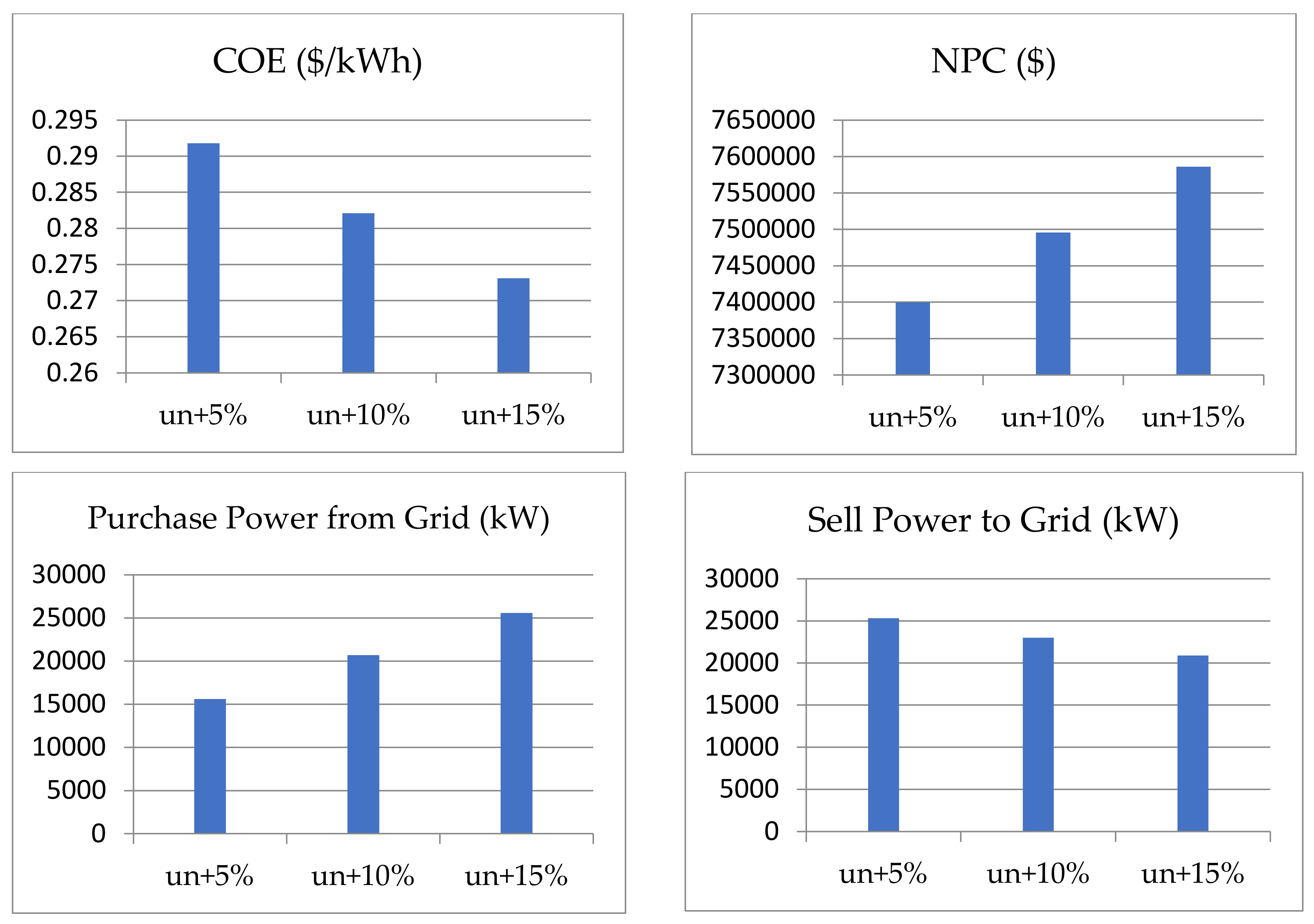
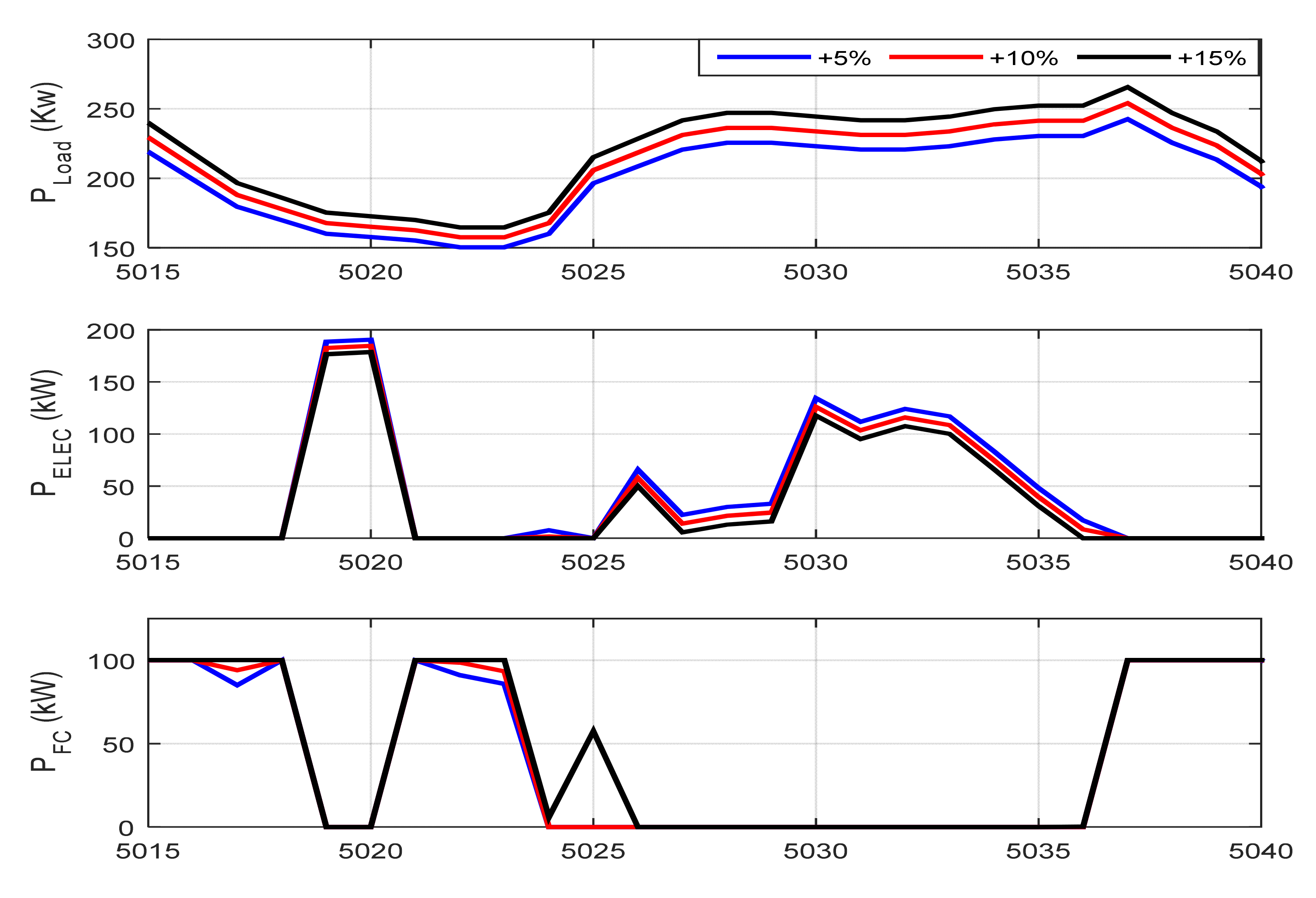
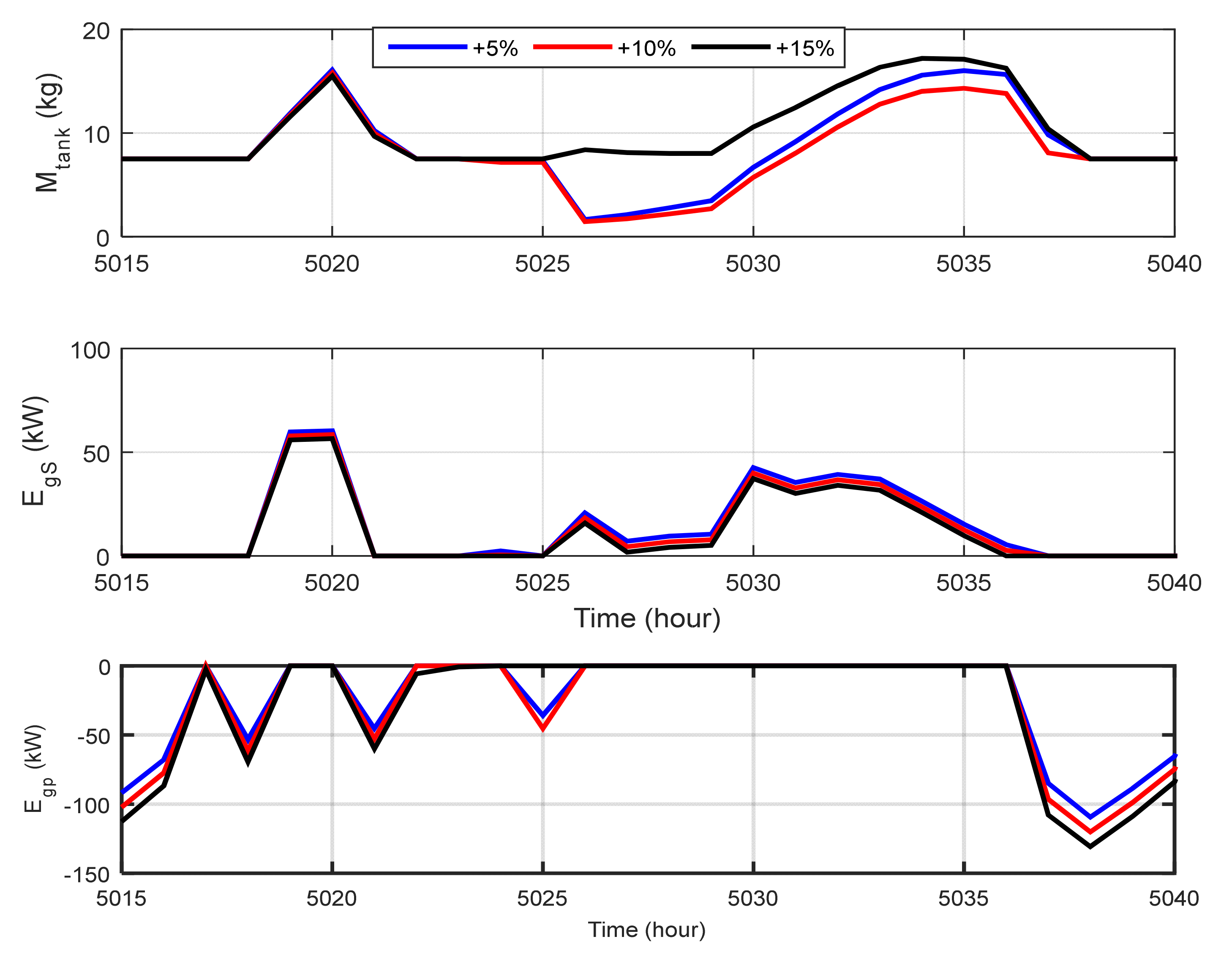
In this case, the results of the HRES are implemented using the MPA technique, considering generation and uncertainty in load demand. Table 3 presents the optimum solution of the optimization parameters based on MPA with +5%, +10%, and +15% uncertainty in the load demand. According to the simulation results in Table 3, considering the load uncertainty, it can be seen that the values of COE are equal to 0.2918$ with +5% uncertainty, 0.2821$ with +10% load uncertainty, and 0.2731$ with +15% load uncertainty. Also, the convergence curve of the optimization algorithm (MPA) with load uncertainty is presented in Figure 13. The comparison is clearly presented in Figure 14, in which the components of the objective function for each optimization method are presented. The results in Figure 15 proved the increase in the total cost of energy as a matter of the consideration of the uncertainty in load demand. Also, the amount of purchased power from the grid is increased to cover the remaining power and decreased in selling power to the grid.

7. Conclusions

In this paper, the optimal sizing of the hybrid renewable energy connected to the grid in Marsa Alam, Egypt, is performed using MPA in MATLAB. This system consists of PV panels, wind turbines, FC, an electrolyzer, a hydrogen tank, and a converter. The main goal of this work is to satisfy the load demand of the proposed location with the minimum COE, while ensuring high power supply reliability and low fluctuations in the energy exchange with the external grid. A comprehensive comparison between MPA and SOA is presented to obtain the optimal case. The simulation results ensure the superiority of MPA in solving the optimization problem and reaching the best optimum solution of the objective function of 0.3044, which represents the minimum values of the COE of 0.3044 $/kWh and LPSP of 4.883 × 10⁻¹⁸, which agree with the predefined values. Moreover, load uncertainty is applied in this study to minimize the total cost of a PV/wind/FC hybrid system and to optimize the system against possible changes in load. The future work should include other formulation of the optimization problem with studying it considering multi-objective function in order to improve the results of the optimal design of the energy systems.

Author Contributions

Conceptualization, A.A.Z.D. and F.S.M.; Data curation, A.A.Z.D. and F.S.M.; Formal analysis, A.A.Z.D. and F.S.M.; Investigation, A.A.Z.D. and A.A.S.; Methodology, A.A.Z.D. and A.A.S.; Project administration, A.A.Z.D. and A.A.S.; Resources, A.A.Z.D.; Software, A.A.Z.D., A.-H.M.E.-S. and F.S.M.; Supervision, A.A.Z.D.; Validation, A.A.Z.D. and F.S.M.; Visualization, A.A.Z.D., A.M.A. and F.S.M.; Writing—original draft, A.A.Z.D. and F.S.M.; Writing—review & editing, A.A.Z.D., F.S.M., A.A.S., A.-H.M.E.-S. and A.M.A. All authors have read and agreed to the published version of the manuscript.

Funding

Research excellence award #8474000427, Khalifa University, Abu Dhabi, UAE.

Institutional Review Board Statement

Not applicable.

Informed Consent Statement

Not applicable.

Data Availability Statement

Not applicable.

Acknowledgments

The authors would like to thank the Deanship o Scientific Research at Umm Al-Qura University for supporting this work by Grant Code: (22UQU4350562DSR04).

Conflicts of Interest

The authors declare no conflict of interest. Non-financial competing interest.

Abbreviations

PVPhotovoltaic.
MPAMarine Predators’ algorithm.
SOASeagull optimization algorithm.
HRESHybrid Renewable Energy Systems.
RESRenewable Energy System.
FCsFuel cells.
PSOParticle Swarm Optimization.
BBABranch-Bound Algorithm.
GAGenetic algorithm.
ICSAImproved crow search algorithm.
RORobust optimization.
PMProbabilistic method.
IGDTInformation gap decision theory.
HPPHybrid possibility probability method.
P pv t   a n d   P w t The generated power by solar PV cell and WT respectively.
WTsWind turbines.
P tot _ w   a n d   P tot _ pv t The total output power generated by a group of wind. turbines and solar PV cells respectively.
P ld The load demand power.
P fc inv The generated power by FC.
P r _ pv The maximum power of PV modules.
n pv   and   n w The number of solar PV cells and WTs.
η wire and   η pv The wiring efficiency and the efficiency of the solar PV cells.
n w   and   η w  
P r _ w
The number of WTs and the WTs efficiency.
The maximum power of the WTs.
λ T The temperature coefficient of the PV modules.
I am t The ambient of solar radiation.
£ p _ pur The Egyptian price for purchasing power from the utility, $/kWh.
P pur _ g The purchasing power from the electric grid.
C sell _ g The proceeds from selling power.
P sell _ g
£ P _ sell
The power sold to the grid.
The Egyptian price (tariff rate) of selling power.
P ele H 2 t The electrolyzer output power(kw).
P ren _ ele The electrolyzer input power(kw).
η ele The efficiency of the electrolyzer.
E H 2 t Δ t   and   E H 2 t t 1 The amount of energy kept in the tank at time t and time (t − 1).
P H 2 t fc t The power supplied to the FCs.
η st _ t The hydrogen tank efficiency.
H H V H 2 The higher heating value of hydrogen.
P H 2 t f c The power input to the FC.
η fc   & η inv The efficiency of the FC and the inverter respectively.
P fc inv
P ren inv
The FC output power.
The output power produced from RES.
P H 2 t f c The FC input power.
F g s The fluctuation rates.
P g s _ max   and   P g s _ min Max and Min surplus power delivered to the main utility, respectively.
COEEnergy cost.
C an _ tot The overall annual cost.
C an _ cap ,   C an _ rep ,   and   C an _ o & m The capital cost of every system component per annum, the replacement cost of every system component per annum, and cost for operation and maintenance every system component per annum, respectively.
C g p and   C g s The annual cost of purchasing and selling energy to the grid, respectively.
C cap _ wt ,   C cap _ fc ,   C cap _ ele ,   C cap _ H 2 t ,   C cap _ pv ,   and   C cap _ con The initial capital cost of the wind turbine, FC, electrolyzer, hydrogen tank, PV module, and converter, respectively.
n wt , n fc ,   n ele ,   n H 2 t ,   n pv ,   and   n con The lifetime of the wind turbine module, FC, electrolyzer, hydrogen tank, PV module, and converter, respectively.
iThe annual interest rate (%).
C R F The capital recovery factor.
n i The lifespan for each subsystem.
C an _ rep Annual replacement cost.
C rep _ i Replacement cost for individual system.
C an _ o & m _ p v ,   C an _ o & m _ w t ,   C an _ o & m _ f c ,   C an _ o & m _ e l e ,   C an _ o & m _ h 2 t ,   and   C an _ o & m _ c o n The operation and maintenance cost of wind turbine, PV modules, FC, electrolyzer, hydrogen tank, and converter, respectively.
t pv ,   t wt ,   t fc ,   t ele ,   t h 2 t ,   and   t con The operating hours for PV, wind turbine, FC, Electrolyzer, hydrogen tank, and converter, respectively.
C pen The penalty costs.
C pen 1 and C pen 2 The penalty costs of the shortage and supply Fluctuation, respectively.
NPCThe net present cost.
M H 2 t _ max   and   M H 2 t _ min The full and the minimum capacity of the hydrogen.
LPSP Loss of power supply probability.
P new y   and   P initial y The new position of candidates after preventing collision and the seagull’s initial position, respectively.
y The present iteration.
M b The agent’s motion in the search space.
y max The maximum number of iterations.
P to _ best y The position in the direction of the best search seagull.
P best y The best position in the searching space at iteration y.
P c _ best y The best-fit searching agent.
P initial y The updating position of the seagulls.
Y 0 The initial value of the parameters.
Y min and   Y max Lower and Upper boundaries of each variable.
i t e r   and   max iter Current iteration and maximum iterations.

References

  1. Liu, X.; Jin, Z. An analysis of the interactions between electricity, fossil fuel and carbon market prices in Guangdong, China. Energy Sustain. Dev. 2020, 55, 82–94. [Google Scholar] [CrossRef]
  2. Qarnain, S.S.; Muthuvel, S.; Bathrinath, S. Review on government action plans to reduce energy consumption in buildings amid COVID-19 pandemic outbreak. Mater. Today Proc. 2021, 45, 1264–1268. [Google Scholar] [CrossRef] [PubMed]
  3. Doshi, R.; Kute, V. A review paper on security concerns in cloud computing and proposed security models. In Proceedings of the 2020 International Conference on Emerging Trends in Information Technology and Engineering (IC-ETITE), Vellore, India, 24–25 February 2020. [Google Scholar]
  4. Hosseini Firouz, M.; Ghadimi, N. Optimal preventive maintenance policy for electric power distribution systems based on the fuzzy AHP methods. Complexity 2016, 21, 70–88. [Google Scholar] [CrossRef]
  5. Rajanna, S.; Saini, R. Modeling of integrated renewable energy system for electrification of a remote area in India. Renew. Energy 2016, 90, 175–187. [Google Scholar] [CrossRef]
  6. Samy, M.M.; Barakat, S. Hybrid invasive weed optimization-particle swarm optimization algorithm for biomass/PV micro-grid power system. In Proceedings of the 2019 21st International Middle East Power Systems Conference (MEPCON), Cairo, Egypt, 17–19 December 2019. [Google Scholar]
  7. Subudhi, P.S.; Krithiga, S. Wireless power transfer topologies used for static and dynamic charging of EV battery: A review. Int. J. Emerg. Electr. Power Syst. 2020, 21, 20190151. [Google Scholar] [CrossRef] [Green Version]
  8. Diab, A.A.Z.; El-Rifaie, A.M.; Zaky, M.M.; Tolba, M.A. Optimal sizing of stand-alone microgrids based on recent metaheuristic algorithms. Mathematics 2022, 10, 140. [Google Scholar] [CrossRef]
  9. Bekele, G.; Boneya, G. Design of a photovoltaic-wind hybrid power generation system for Ethiopian remote area. Energy Procedia 2012, 14, 1760–1765. [Google Scholar] [CrossRef] [Green Version]
  10. Belatrache, D.; Saifi, N.; Harrouz, A.; Bentouba, S. Modelling and Numerical Investigation of the thermal properties effect on the soil temperature in Adrar region. Alger. J. Renew. Energy Sustain. Dev. 2020, 2, 165–174. [Google Scholar] [CrossRef]
  11. Bhattacharjee, S.; Acharya, S. PV–wind hybrid power option for a low wind topography. Energy Convers. Manag. 2015, 89, 942–954. [Google Scholar] [CrossRef]
  12. Kaur, R.; Krishnasamy, V.; Kandasamy, N.K. Optimal sizing of wind–PV-based DC microgrid for telecom power supply in remote areas. IET Renew. Power Gener. 2018, 12, 859–866. [Google Scholar] [CrossRef]
  13. Khare, V.; Nema, S.; Baredar, P. Solar–wind hybrid renewable energy system: A review. Renew. Sustain. Energy Rev. 2016, 58, 23–33. [Google Scholar] [CrossRef]
  14. Mouli, G.C.; Bauer, P.; Zeman, M. System design for a solar powered electric vehicle charging station for workplaces. Appl. Energy 2016, 168, 434–443. [Google Scholar] [CrossRef] [Green Version]
  15. Nehrir, M.; Wang, C.; Strunz, K.; Aki, H.; Ramakumar, R.; Bing, J.; Miao, Z.; Salameh, Z. A review of hybrid renewable/alternative energy systems for electric power generation: Configurations, control, and applications. IEEE Trans. Sustain. Energy 2011, 2, 392–403. [Google Scholar] [CrossRef]
  16. Wang, L.; Singh, C. Multicriteria design of hybrid power generation systems based on a modified particle swarm optimization algorithm. IEEE Trans. Energy Convers. 2009, 24, 163–172. [Google Scholar] [CrossRef]
  17. Lei, G.; Song, H.; Rodriguez, D. Power generation cost minimization of the grid-connected hybrid renewable energy system through optimal sizing using the modified seagull optimization technique. Energy Rep. 2020, 6, 3365–3376. [Google Scholar] [CrossRef]
  18. Badr, M.A.E.S. Hybrid Wind and Solar Systems Optimization. In Modeling, Simulation and Optimization of Wind Farms and Hybrid Systems; IntechOpen: London, UK, 2020; p. 262. [Google Scholar]
  19. Barakat, S.; Ibrahim, H.; Elbaset, A.A. Multi-objective optimization of grid-connected PV-wind hybrid system considering reliability, cost, and environmental aspects. Sustain. Cities Soc. 2020, 60, 102178. [Google Scholar] [CrossRef]
  20. Das, D.; Esmaili, R.; Xu, L.; Nichols, D. An optimal design of a grid connected hybrid wind/photovoltaic/fuel cell system for distributed energy production. In Proceedings of the 31st Annual Conference of IEEE Industrial Electronics Society, IECON 2005, Raleigh, NC, USA, 6–10 November 2005; p. 6. [Google Scholar]
  21. Samy, M.M.; Mosaad, M.I.; Barakat, S. Optimal economic study of hybrid PV-wind-fuel cell system integrated to unreliable electric utility using hybrid search optimization technique. Int. J. Hydrog. Energy 2021, 46, 11217–11231. [Google Scholar] [CrossRef]
  22. Banhidarah, A.K.; Al-Sumaiti, A.S. Heuristic search algorithms for optimal locations and sizing of distributed generators in the grid: A brief recent review. In Proceedings of the 2018 Advances in Science and Engineering Technology International Conferences (ASET), Dubai, Sharjah, Abu Dhabi, United Arab Emirates, 6 February–5 April 2018; pp. 1–5. [Google Scholar]
  23. Yuan, G.; Gao, Y.; Ye, B.; Huang, R. Real-time pricing for smart grid with multi-energy microgrids and uncertain loads: A bilevel programming method. Int. J. Electr. Power Energy Syst. 2020, 123, 106206. [Google Scholar] [CrossRef]
  24. Dufo-López, R.; Bernal-Agustín, J.L.; Yusta-Loyo, J.M.; Domínguez-Navarro, J.A.; Ramírez-Rosado, I.J.; Lujano, J.; Aso, I. Multi-objective optimization minimizing cost and life cycle emissions of stand-alone PV–wind–diesel systems with batteries storage. Appl. Energy 2011, 88, 4033–4041. [Google Scholar] [CrossRef]
  25. Tafreshi, S.; Zamani, H.; Ezzati, S.; Baghdadi, M.; Vahedi, H. Optimal unit sizing of distributed energy resources in microgrid using genetic algorithm. In Proceedings of the 2010 18th Iranian Conference on Electrical Engineering, Isfahan, Iran, 11–13 May 2010; pp. 836–841. [Google Scholar]
  26. Hadidian-Moghaddam, M.; Arabi-Nowdeh, S.; Bigdeli, M. Optimal sizing of a stand-alone hybrid photovoltaic/wind system using new grey wolf optimizer considering reliability. J. Renew. Sustain. Energy 2016, 8, 035903. [Google Scholar] [CrossRef]
  27. Bilal, M.; Alsaidan, I.; Alaraj, M.; Almasoudi, F.M.; Rizwan, M. Techno-Economic and Environmental Analysis of Grid-Connected Electric Vehicle Charging Station Using AI-Based Algorithm. Mathematics 2022, 10, 924. [Google Scholar] [CrossRef]
  28. Moghaddam, S.; Bigdeli, M.; Moradlou, M. Optimal design of an off-grid hybrid renewable energy system considering generation and load uncertainty: The case of Zanjan city, Iran. SN Appl. Sci. 2021, 3, 732. [Google Scholar] [CrossRef]
  29. Yan, J.; Zhang, H.; Liu, Y.; Han, S.; Li, L. Uncertainty estimation for wind energy conversion by probabilistic wind turbine power curve modelling. Appl. Energy 2019, 239, 1356–1370. [Google Scholar] [CrossRef]
  30. Li, K.; Song, Y.; Wang, R. Multi-Objective Optimal Sizing of HRES under Multiple Scenarios with Undetermined Probability. Mathematics 2022, 10, 1508. [Google Scholar] [CrossRef]
  31. Ahn, H.; Rim, D.; Pavlak, G.S.; Freihaut, J.D. Uncertainty analysis of energy and economic performances of hybrid solar photovoltaic and combined cooling, heating, and power (CCHP+ PV) systems using a Monte-Carlo method. Appl. Energy 2019, 255, 113753. [Google Scholar] [CrossRef]
  32. Thevenard, D.; Pelland, S. Estimating the uncertainty in long-term photovoltaic yield predictions. Sol. Energy 2013, 91, 432–445. [Google Scholar] [CrossRef]
  33. Zubo, R.H.; Mokryani, G.; Rajamani, H.-S.; Aghaei, J.; Niknam, T.; Pillai, P. Operation and planning of distribution networks with integration of renewable distributed generators considering uncertainties: A review. Renew. Sustain. Energy Rev. 2017, 72, 1177–1198. [Google Scholar] [CrossRef] [Green Version]
  34. Samper, M.E.; Vargas, A. Investment decisions in distribution networks under uncertainty with distributed generation—Part II: Implementation and results. IEEE Trans. Power Syst. 2013, 28, 2341–2351. [Google Scholar] [CrossRef]
  35. Beza, T.M.; Wu, C.-H.; Kuo, C.-C. Optimal Sizing and Techno-Economic Analysis of Minigrid Hybrid Renewable Energy System for Tourist Destination Islands of Lake Tana, Ethiopia. Appl. Sci. 2021, 11, 7085. [Google Scholar] [CrossRef]
  36. Smaoui, M.; Krichen, L. Design and energy control of stand-alone hybrid wind/photovoltaic/fuel cell power system supplying a desalination unit. J. Renew. Sustain. Energy 2014, 6, 043111. [Google Scholar] [CrossRef]
  37. Ghenai, C.; Salameh, T.; Merabet, A. Technico-economic analysis of off grid solar PV/Fuel cell energy system for residential community in desert region. Int. J. Hydrog. Energy 2020, 45, 11460–11470. [Google Scholar] [CrossRef]
  38. Khan, M.J.; Mathew, L.; Alotaibi, M.A.; Malik, H.; Nassar, M.E. Fuzzy-Logic-Based Comparative Analysis of Different Maximum Power Point Tracking Controllers for Hybrid Renewal Energy Systems. Mathematics 2022, 10, 529. [Google Scholar] [CrossRef]
  39. Diab, A.A.Z.; Sultan, H.M.; Mohamed, I.S.; Kuznetsov, O.N.; Do, T.D. Application of different optimization algorithms for optimal sizing of PV/wind/diesel/battery storage stand-alone hybrid microgrid. IEEE Access 2019, 7, 119223–119245. [Google Scholar] [CrossRef]
  40. Diab, A.A.Z.; Sultan, H.M.; Kuznetsov, O.N. Optimal sizing of hybrid solar/wind/hydroelectric pumped storage energy system in Egypt based on different meta-heuristic techniques. Environ. Sci. Pollut. Res. 2020, 27, 32318–32340. [Google Scholar] [CrossRef]
  41. Yang, H.; Wei, Z.; Chengzhi, L. Optimal design and techno-economic analysis of a hybrid solar–wind power generation system. Appl. Energy 2009, 86, 163–169. [Google Scholar] [CrossRef]
  42. Mousa, H.H.; Youssef, A.-R.; Mohamed, E.E. Variable step size P&O MPPT algorithm for optimal power extraction of multi-phase PMSG based wind generation system. Int. J. Electr. Power Energy Syst. 2019, 108, 218–231. [Google Scholar]
  43. Asadi Bagal, H.; Mir Mousavi, M.m.; Janghorban Lariche, M.; Mohammadinodoushan, M.; Hayati, H. Wind power penetration impact on power system frequency. Int. J. Ambient. Energy 2019, 40, 455–462. [Google Scholar] [CrossRef]
  44. Malheiro, A.; Castro, P.M.; Lima, R.M.; Estanqueiro, A. Integrated sizing and scheduling of wind/PV/diesel/battery isolated systems. Renew. Energy 2015, 83, 646–657. [Google Scholar] [CrossRef] [Green Version]
  45. Diab, A.A.Z.; El-ajmi, S.I.; Sultan, H.M.; Hassan, Y.B. Modified farmland fertility optimization algorithm for optimal design of a grid-connected hybrid renewable energy system with fuel cell storage: Case study of Ataka, Egypt. Int. J. Adv. Comput. Sci. Appl. 2019, 10, 119–132. [Google Scholar] [CrossRef] [Green Version]
  46. Ott, S.; Orfanidi, A.; Schmies, H.; Anke, B.; Nong, H.N.; Hübner, J.; Gernert, U.; Gliech, M.; Lerch, M.; Strasser, P. Ionomer distribution control in porous carbon-supported catalyst layers for high-power and low Pt-loaded proton exchange membrane fuel cells. Nat. Mater. 2020, 19, 77–85. [Google Scholar] [CrossRef] [PubMed]
  47. Singla, M.K.; Nijhawan, P.; Oberoi, A.S. Hydrogen fuel and fuel cell technology for cleaner future: A review. Environ. Sci. Pollut. Res. 2021, 28, 15607–15626. [Google Scholar] [CrossRef]
  48. Singla, M.K.; Nijhawan, P.; Oberoi, A.S. Parameter estimation of proton exchange membrane fuel cell using a novel meta-heuristic algorithm. Environ. Sci. Pollut. Res. 2021, 28, 34511–34526. [Google Scholar] [CrossRef]
  49. Singla, M.K.; Nijhawan, P.; Oberoi, A.S. Cost–benefit comparison of fuel cell–based and battery-based renewable energy systems. Int. J. Energy Res. 2022, 46, 1736–1755. [Google Scholar] [CrossRef]
  50. Xu, L.; Ruan, X.; Mao, C.; Zhang, B.; Luo, Y. An improved optimal sizing method for wind-solar-battery hybrid power system. IEEE Trans. Sustain. Energy 2013, 4, 774–785. [Google Scholar]
  51. Dhiman, G.; Kumar, V. Seagull optimization algorithm: Theory and its applications for large-scale industrial engineering problems. Knowl.-Based Syst. 2019, 165, 169–196. [Google Scholar] [CrossRef]
  52. Sattar, M.A.E.; Al Sumaiti, A.; Ali, H.; Diab, A.A.Z. Marine predators algorithm for parameters estimation of photovoltaic modules considering various weather conditions. Neural Comput. Appl. 2021, 33, 11799–11819. [Google Scholar] [CrossRef]
  53. Askari, Q.; Younas, I.; Saeed, M. Political Optimizer: A novel socio-inspired meta-heuristic for global optimization. Knowl.-Based Syst. 2020, 195, 105709. [Google Scholar] [CrossRef]
Figure 1. This is a figure of a hybrid renewable energy system connected to a grid.
Mathematics 10 03708 g001
Figure 2. Management strategy for the hybrid energy system.
Mathematics 10 03708 g002
Figure 3. Description of SOA optimization algorithm.
Mathematics 10 03708 g003
Figure 4. MPA optimization algorithm.
Mathematics 10 03708 g004
Figure 5. Egypt’s wind energy map.
Mathematics 10 03708 g005
Figure 6. Egypt’s solar radiation intensity.
Mathematics 10 03708 g006
Figure 7. Average annual variation of wind speed and solar radiation for the study area.
Mathematics 10 03708 g007
Figure 8. Average annual variation of the load demand for the study area.
Mathematics 10 03708 g008
Figure 9. Convergence curves when deploying the optimization algorithms (MPA, SOA and PSO).
Mathematics 10 03708 g009
Figure 10. Comparison of the optimization parameters of MPA and SOA.
Mathematics 10 03708 g010
Figure 11. Results of the optimal solution for MPA at 8760 h.
Mathematics 10 03708 g011aMathematics 10 03708 g011b
Figure 12. Results of the optimal solution using MPA for one day when operating in summer.
Mathematics 10 03708 g012
Figure 13. Convergence curves of the optimization algorithm (MPA) with load uncertainty.
Mathematics 10 03708 g013
Figure 14. Comparison of the optimization parameters for MPA in case load uncertainty.
Mathematics 10 03708 g014
Figure 15. Results of the optimization technique MPA of a certain day of operation in summer with uncertainty in load (+5%, +10%, and +15%).
Mathematics 10 03708 g015aMathematics 10 03708 g015b
Table 1. Economic specifications of the system components.
ParametersWind TurbinePV ArrayElctrolyzerHydrogen TankFuel CellInverter
Capital cost (US$/unit) 118,412 136,912 52,311 17,004 71,219.2 12,387
Replacement cost (US$/unit) 52,500 22,500 9000 50,000 7500
O & M   cost (US$/unit-yr) 5250 5000 7500 2250.4 17,500 1203.02
Lifetime(year) 20 25 20 20 5 15
Table 2. Results of the optimization parameters based on MPA, SOA, and PSO.
ItemsOptimal Solution
MPASOAPSO
Best objective function1.01021.01691.46433350572227
n _PVs250250500
n _WT707070
Electrolyzer rated power (kW)300300442.6293
Mass of the H2 tanks (kg)150150135.7179
FC rated power kW)100100250
Inverter rated power (kW)150150510.4037
Number of iterations to attain an optimal solution53PSO does not reach to the optimum.
COE ($/kWh)0.30440.31150.5176
LPSP−4.883 × 10⁻¹⁸−9.7063 × 10⁻¹⁹−3.461 × 10⁻¹⁵
NPC ($)7.350895 × 1067.523017 × 1061.2498 × 107
Sold power to the grid ( P g S )27.82 × 10327.821 × 1035.0515 × 104
Purchased power from the grid ( P g p ) 14.22 × 10327.737 × 1032.7878 × 103
Table 3. Results of the optimization parameters based on MPA with load uncertainty.
ItemsLoad Uncertainty
+5%+10%+15%
Best objective function1.01021.01021.0102
n_PVs250250250
n_WT707070
Electrolyzer rated power of (kW)300300300
Mass of the H2 tanks (kg)150150150
FC rated power kW)100100100
Inverter rated power (kW)150150150
Number of iterations to attain an optimal solution749
COE ($/kWh)0.29180.28210.2731
LPSP−4.285 × 10⁻¹⁸−5.328 × 10⁻¹⁸−5.6198 × 10⁻¹⁸
NPC ($)7.399616 × 1067.495652 × 1067.586028 × 106
Sold power to the grid ( P g S )25.321 × 10323.005 × 10320.893 × 103
Purchased power from the grid ( P g p ) 15.585 × 10320.729 × 10325.568 × 103
Publisher’s Note: MDPI stays neutral with regard to jurisdictional claims in published maps and institutional affiliations.