Article

Research on a Real-Time Monitoring Method for the Three-Dimensional Straightness of a Scraper Conveyor Based on Binocular Vision

1
State Laboratory of Coal Resources and Safe Mining, China University of Mining and Technology, Xuzhou 221116, China
2
School of Mines, China University of Mining and Technology, Xuzhou 221116, China
*
Author to whom correspondence should be addressed.
Mathematics 2022, 10(19), 3545; https://doi.org/10.3390/math10193545
Submission received: 15 July 2022 / Revised: 23 August 2022 / Accepted: 19 September 2022 / Published: 28 September 2022
(This article belongs to the Special Issue Modeling and Simulation for the Electrical Power System)

Abstract

:
Measuring the straightness of the scraper conveyor, which is an indispensable piece of equipment in a fully mechanized coal face, can prevent accidents such as derailment of the shearer and is also important for the precise positioning of the shearer and the accurate control of the hydraulic support. The existing scraper conveyor straightness measurement methods have the disadvantages of inconsistent measurement cost, accuracy, and reliability as well as low dimension of straightness description. To this end, this paper proposes a method for monitoring the three-dimensional straightness of a scraper conveyor based on binocular vision. Trapezoidal window matching technology was used to realize the image acquisition of multiple stations and multiple sensors. The bit pose acquisition model of binocular vision 3D reconstruction was used to obtain the 3D coordinates of the feature points on the sign board in each local coordinate system and the bit pose information of each sign board. The pose relay videometric method was used to convert the straightness in each local coordinate system to the global coordinate system to realize the 3D reconstruction of the scraper conveyor. Finally, the straightness measurement test of the preset scraper conveyor was carried out, and the error analysis was carried out by comparing with the manual measurement results, which showed that the measurement errors were all within ±30 mm. At the same time, the standard deviation of errors in both directions was small, which indicates that the straightness measurement method for the scraper conveyor in this paper has high reliability. In addition, the visual measurement process is independent of each other, so there is no error accumulation in the visual straightness measurement method. The analysis shows that the method of measuring the straightness of a scraper conveyor based on binocular vision can realize continuous and real-time monitoring of the scraper conveyor.

1. Introduction

Under the development trend of large-scale mines, intelligent mining has become the core technology support for the transformation and upgradation of the coal industry [1,2], among which, realizing the precise perception of the mine is an important foundation for the intelligent construction of the mine. Meanwhile, the straightness problem of the scraper conveyor, as an indispensable piece of equipment in the fully mechanized coal face, will affect the precise positioning of the shearer and the accurate control of the hydraulic support [3,4]. Moreover, the lack of straightness will worsen the scraper chain wear and, in serious cases, will lead to the shearer derailment [5,6,7,8]. Therefore, it is important to sense the straightness of the scraper conveyor in real time and with accuracy.
Currently, more research has been conducted by scholars on the problem of the straightness of the scraper conveyor. The Australian Commonwealth Scientific and Industrial Research Organization (CSIRO) proposed to detect the 3D trajectory of the shearer and, thus, inverse the morphology of the scraper conveyor by means of the strap-down inertial navigation technique [9]. Subsequently, several scholars have studied it in depth and achieved autonomous positioning of shearer by installing sensors such as gyroscopes and accelerometers on the shearer [10,11,12]. However, this method is affected by the vibration of the shearer and has high environmental requirements, and the measured straightness error is within ±640 mm, which is far from the requirement of ±50 mm for straightening accuracy of the coal face [4,13]. Other scholars have used a fiber grating to measure the straightness of the scraper conveyor [3,4], which is a simple technical method with simple facilities that is easy to implement and has high accuracy, but the optical fiber strainometer is expensive and the measurement cost is relatively high, while it is easily destroyed in the complex environment of the working, and the reliability needs to be further improved [13]. In recent years, machine vision measurement methods have developed considerably [13,14] and are widely used in pharmaceutical, chemical, automotive, and industrial industries because of their high accuracy, continuity, cost effectiveness, and flexibility. Based on this, some scholars applied it to scraper conveyor trajectory monitoring [13,14,15,16], and the measured scraper conveyor straightness error was less than ±50 mm [13], which meets the coal face straightening accuracy requirement. However, most of the reports related to vision-based straightness measurement of scraper conveyors have monitored the two-dimensional trajectory of the scraper conveyor, and there are fewer studies on the use of vision technology to obtain the information of the middle chute pose, which leads to the lack of accurate description of the spatial morphology of the scraper conveyor, thus affecting the positioning accuracy of the shearer and the accurate control of the hydraulic support. Therefore, it is necessary to conduct an in-depth study on the vision-based method of acquiring the middle chute pose of the scraper conveyor, and based on this, a further study on the method of measuring the three-dimensional straightness of the scraper conveyor.
The idea of the straightness measurement of a scraper conveyor based on vision technology is to obtain the image signal of the scraper conveyor using vision sensors and then apply vision algorithms to reconstruct the scraper conveyor in three dimensions [17,18,19]. However, the scraper conveyor of the fully mechanized coal face is long, and it is currently difficult for one vision sensor to obtain its complete image information. Therefore, how to use the computer to control multiple vision sensors to complete the image acquisition work and how to convert multiple independent local coordinate systems into a unified global coordinate system are the key issues to realize the visual measurement of the scraper conveyor’s straightness.
This paper proposes a real-time monitoring method for three-dimensional straightness of a scraper conveyor based on binocular vision technology, establishes a position acquisition model for three-dimensional reconstruction of binocular vision, and designs a visual measurement system for the straightness of a scraper conveyor. Based on this, a visual measurement model was built, and laboratory tests were conducted. The visual measurement error is discussed and analyzed by comparing with the manually measured straightness of the scraper conveyor.

2. Scraper Conveyor Straightness Visual Relay Measurement Method

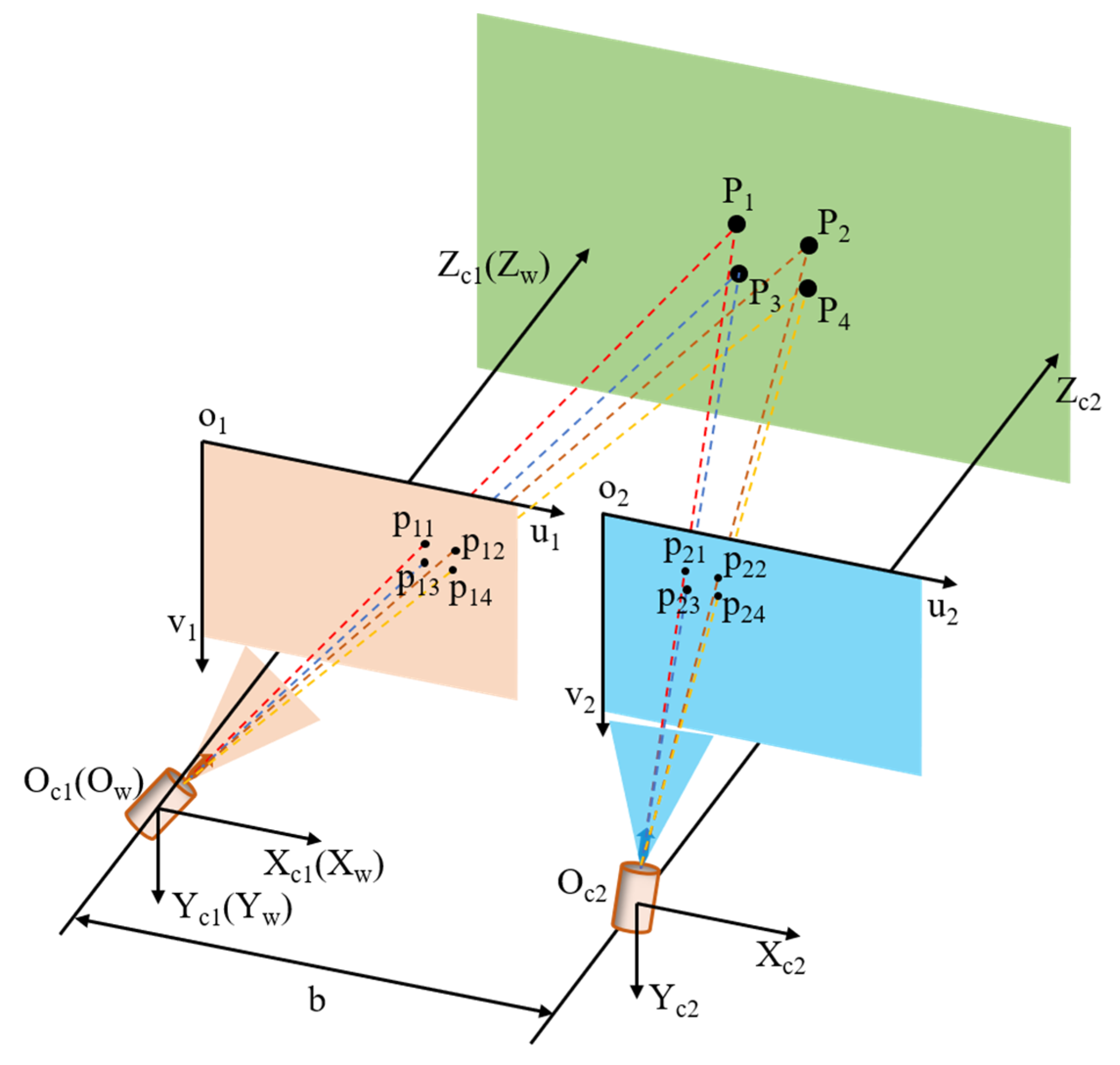
2.1. Target Pose Acquisition Model Based on Binocular Vision 3D Reconstruction

In this paper, the target is reconstructed in three dimensions based on binocular vision techniques [20,21], based on which the target pose is solved by using the principle of the P4P algorithm [22,23,24], the basic principle of which is shown in Figure 1. The model contains a total of three coordinate systems, namely, the world coordinate system ( O w X w Y w Z w ), the camera coordinate system ( O c X c Y c Z c ), and the image pixel coordinate system ( O x y ). Among them, the internal parameters of the left and right cameras are the same, and the X-axes of the two camera coordinate systems overlap and the Y-axes are parallel. Meanwhile, the main optical axis is perpendicular to the camera image plane, and the world coordinate system coincides with the 1# camera coordinate system. Moreover, the axes of the same direction in different coordinate systems are parallel to each other.
In Figure 1, Oc1 and Oc2 are the optical centers of the left and right cameras, respectively, and the distance between them is b. p1i, p2i (i = 1~4) are the projection points of the target P i w = ( X w i , Y w i , Z w i ) in the imaging planes of the Oc1 and Oc2 optical centers, and their coordinates are P 1 i = ( u 1 i , v 1 i ) and P 2 i = ( u 2 i , v 2 i ) under the respective camera pixel coordinate systems. According to the relationship between similar triangles, it is obtained that
u 1 i = f X w i Z w i
u 2 i = f ( X w i b ) Z w i
v 1 i = v 2 i = f Y w i Z w i
where f is the focal length of the two cameras.
Then, the parallax of the two image points is
d = ( u 1 i u 2 i ) = f × b Z w i
where d is the parallax of the two image points.
From Equation (4), it can be seen that, in the binocular vision 3D reconstruction-based positional acquisition model, when the parallax d, the camera focal length f, and the distance b between the optical center points of the two cameras are determined, the 3D coordinates of the target point in the world coordinate system can be obtained as P i w = ( X w i , Y w i , Z w i ) .The coordinates of point P i in the world coordinate system and the pixel coordinates p 1 i = ( u 1 i , v 1 i ) it makes in camera 1# can be converted as follows:
Z c i u i v i 1 = 1 d x 0 u 0 0 1 d y v 0 0 0 1 f 0 0 0 f 0 0 0 1 0 0 0 R t 0 1 X W i Y W i Z W i 1 = N 1 N 2 X W i Y W i Z W i 1
where N1 is the internal parameter of the camera, which can be obtained through calibration experiments. N2 is the external parameter of the camera, which mainly consists of two parameters: the rotation matrix R − 1 and the translation vector t .
The binocular vision algorithm can solve for the world coordinates corresponding to the pixel coordinates of feature points, and the internal parameters of the camera can be obtained through calibration experiments, and then the external parameters of the camera, N2, can be solved, where the rotation matrix is
R = r 11 r 12 r 13 r 21 r 22 r 23 r 31 r 32 r 33
Then, the roll angle ( θ x ), pitch angle ( θ y ), and azimuth angle ( θ z ) can be solved from the rotation matrix.
θ x = a tan r 32 / r 33
θ y = a tan r 31 / r 32 2 + r 33 2
θ z = a tan r 21 / r 11
From Equation (4) to Equation (9), it is shown that in the case of known points of one image, feature matching needs to be performed in another image to find the corresponding image points, so as to establish the project image pair to complete the 3D reconstruction of the target body. Then, based on the coordinate conversion algorithm, the pose information of the target can be obtained by combining the in-camera parameters. Among them, the feature matching [25] process can be divided into four stages. First, the pixel values of the target feature points are extracted, and the descriptors of the feature points are calculated. Second, under the same rules, the image coordinate systems are established separately for two cameras, and then, the two image coordinate systems are rotated and translated to make the established image coordinate systems coincide completely. Third, in one of the camera images, feature markers are recognized and matched based on the descriptors of the feature points and the image coordinate system region of the feature points is located. Finally, the feature markers are positioned in the region of the coordinate system corresponding to the one for the other camera image.

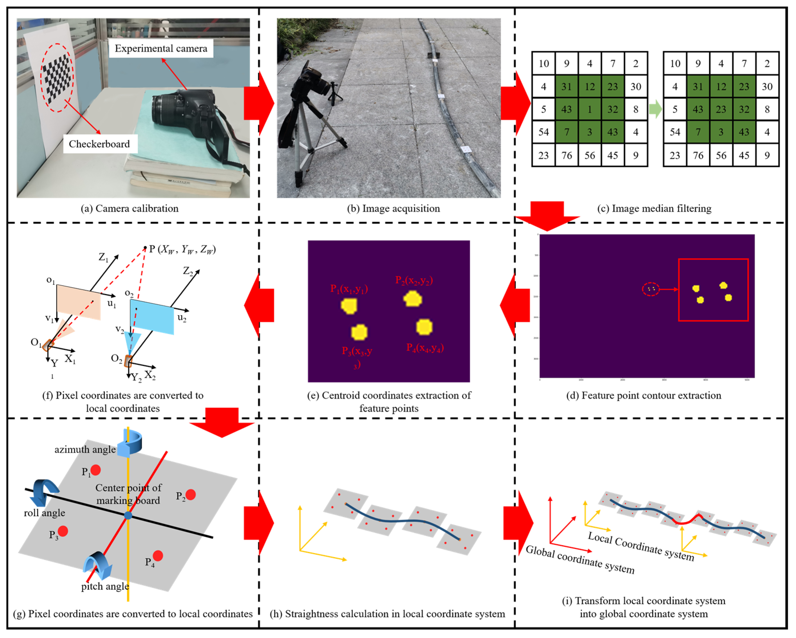
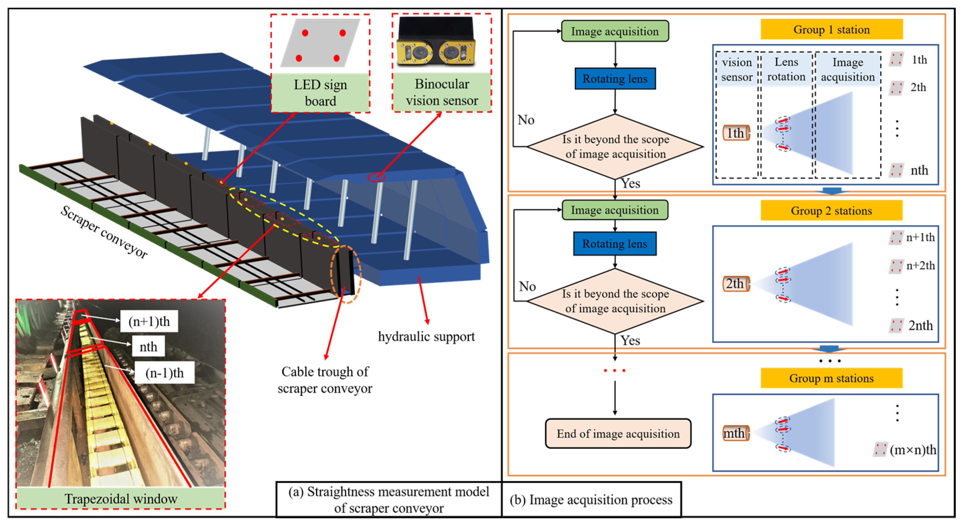
2.2. Scraper Conveyor Straightness Visual Relay Measurement Method

This paper proposes the measurement method based on binocular vision principle of “visual relay” to measure the straightness of a scraper conveyor. Firstly, multiple stations are set up at the lower end of the hydraulic support roof beam along the coal face; each station is equipped with a binocular vision sensor, and an LED sign board is set up at the cable slot side of each middle chute of the scraper conveyor by measuring the straightness of the sign board to characterize the straightness of the scraper conveyor. Then, the trapezoidal window matching technique [13,26] is used so that the vision sensor only acquires the image of the sign board on one of the middle chutes at any moment. After the acquisition of this sign board image is completed, the computer controls the sensor lens to rotate by a certain angle for the acquisition of the next middle chute sign board image, and so on, so that the trapezoidal window slides from the near end to the far end of the sensor, as shown in Figure 2. When the sensor completes the image acquisition task of the scraper conveyor section “radiated” by this station, the sensor of the next station takes over the image acquisition work (visual relay) and repeats the above steps. Finally, the straightness of the scraper conveyor at each station is unified under the global coordinate system using the pose relay videometric method [27,28], which is given as follows:
R 1 , n = i = 1 n 1 R n i , n i + 1 = R n 1 , n R n 2 , n 1 , , R 1 , 2 t 1 , n = i = 1 n 2 ( j = 0 n 2 i R n j 1 , n j ) t i , i + 1 + t n 1 , n
where R 1 , n , t 1 , n is the straightness relationship between the first-level relay camera transfer to the nth-level relay camera. t i , i + 1 is the straightness relationship between the relay camera at level i and the relay camera at level i + 1, and its value can be obtained by solving the straightness of the images captured by the relay camera at that level. n is the number of cameras.

3. Scraper Conveyor Straightness Binocular Vision Measurement System and Experimental Model

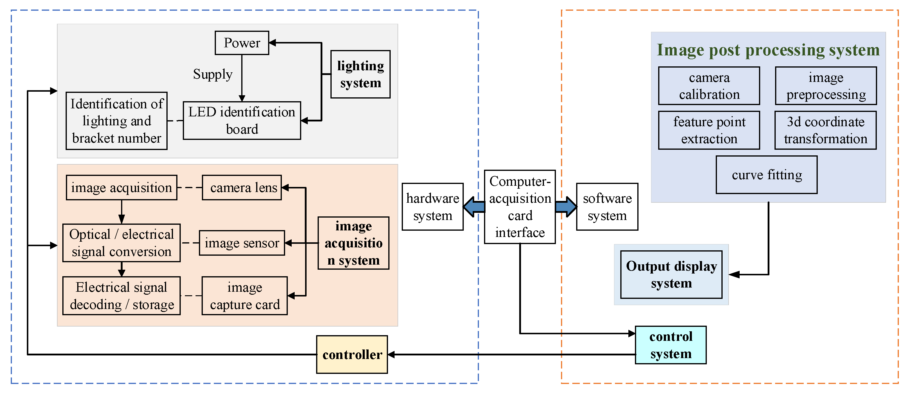
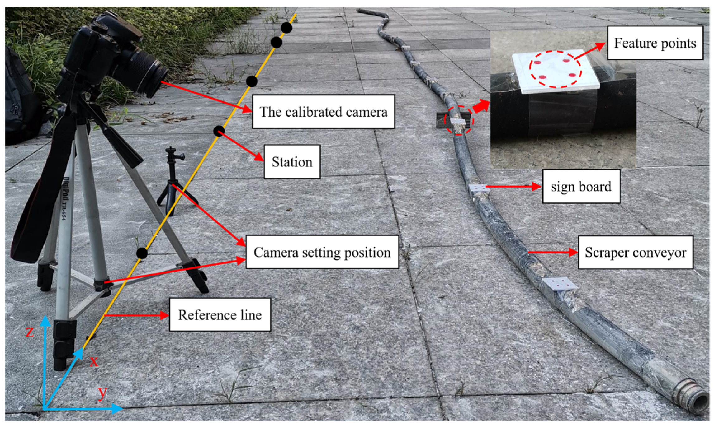
3.1. Scraper Conveyor Straightness Binocular Vision Measuring System

In this paper, a binocular vision measurement system for scraper conveyors designed based on the proposed straightness measurement method for scraper conveyor is described, see Figure 3. The whole measurement system contains five subsystems, which are the lighting system, the image acquisition system, the probe control system, the image post-processing system, and the display system.
The lighting system is to set an LED sign board on the cable slot side of the middle chute of each scraper conveyor, and the lighting on and off of each LED sign board is controlled through a wireless sensor network, so that the camera only acquires the feature point information of a certain sign board at one time. It can effectively reduce the impact of backlighting and dust on image acquisition at the coal face; meanwhile, it can grasp the hydraulic bracket number corresponding to each sign board.
The image acquisition system is mainly composed of the optical lens, the image sensor, the image acquisition card, and the controller. During the measurement, the probe control system is used to control the optical lens to obtain the feature point information of the middle chute, and the image sensor is used to convert the optical signal into an electrical signal, and then, the image acquisition card is used to realize the decoding of the electrical signal so that the digital image is stored in its own cache space. After the image acquisition is completed, the digital image signal is transmitted to the image post-processing system through the supporting computer capture card interface, and the subsequent spatial straightness of the scraper conveyor is characterized through the output display system.

3.2. Experimental Model by Binocular Visual Measurement of the Straightness of the Scraper Conveyor

Based on the above binocular vision measurement system, the experimental model is designed as shown in Figure 4, where the rubber tube represents a scraper conveyor in accordance with the actual underground situation, and the sign board is set at 300, 900, 1500, 2100, 2700, 3300, 3900, 4500, 5100, and 5700 mm before the x-direction on the rubber tube. A total of five stations are set up along the x-direction at 600, 1800, 3000, 4200, and 5400 mm in front of the x-direction, with two calibrated cameras in each station instead of binocular vision sensors. Meanwhile, the x direction is the direction of the shearer operation, the y direction is the direction of coal face advancement, and the z direction is the vertical direction.

4. Experimental Study of the Straightness Measurement of a Scraper Conveyor Based on Binocular Vision

The straightness measurement experimental process of the scraper conveyor based on binocular vision in this paper is shown in Figure 5. Before the experiment, the calibration of the test camera was carried out using the Zhang Zhengyou checkerboard method [29,30], which designed the checkerboard grid board as a 7 × 10 black-and-white square grid with each square sized 12 mm × 12 mm, with the calibration camera model as EOS 600D mining explosion-proof camera, as shown in Figure 5a. The calibration test was performed by taking 12 checkerboard images from different angles and then extracting the corner point information of each image, followed by further extracting its sub-pixel corner point information and, finally, completing the calibration of the camera.
After the camera calibration is completed, images of each sign board of the pre-set scraper conveyor are acquired with the use of the scraper conveyor straightness visual measurement test model, as shown in Figure 5b. Before image acquisition, two base points are pre-set in advance in each measurement station by the placement of the camera as a substitute for the binocular vision sensor. During image acquisition, the images of the sign board are acquired sequentially along the x-direction, and in order to avoid the influence of unclear images on the test results, two images of the same sign board should be acquired by each camera.
After the image acquisition is completed, the clearest image of the same sign board taken by each camera is selected, and the noise reduction process of median filtering is performed. Then the Canny algorithm is applied to detect the edges of the feature points and extract the center-of-mass pixel coordinates of the feature point contours on each sign board. Subsequently, the coordinate conversion principle is used to convert the coordinates of each pixel into coordinates under the coordinate system of each measuring station, from which information on the pose of each middle chute of the scraper conveyor and on the straightness of each section of the scraper conveyor within the local coordinate system is obtained. Finally, the pose relay videometric method is used to transfer the local coordinate system to the global coordinate system for each segment of the scraper conveyor, so that the complete 3D form of the scraper conveyor in the global coordinate system is obtained.

5. Results and Discussion

5.1. Scraper Conveyor Straightness Measurement Results

Through the visual measurement experiment to determine the straightness of the scraper conveyor, the three-dimensional coordinates of the feature points on each sign board in its local coordinate system are obtained and further calculated to obtain the pose of the middle chute of each section, and the results are shown in Table 1.
The pose relay videometric method is used to convert the information regarding the local straightness of the scraper conveyor to the reference coordinate system shown in Figure 5, thus obtaining the spatial straightness information of the pre-set scraper conveyor, as shown in Figure 6.
As can be seen from Figure 6, the visual measurement results of the straightness of the scraper conveyor are in good agreement with the manual measurement results, and the minimum measurement errors in both directions are located at the starting point, and the maximum measurement errors are located at 4500 mm before the x-direction. In the horizontal direction, the minimum relative displacement between two adjacent middle chutes measured visually was 7 mm and the maximum relative displacement was 72.5 mm, while the minimum relative displacement between two adjacent middle chutes measured manually was 2 mm and the maximum relative displacement was 105 mm. In addition, there are measurement anomalies at 2100 mm and 5100 mm before the x-direction, i.e., the center point of the sign board measured by vision deviates from the true trajectory trend line of the scraper conveyor. In the vertical direction, the minimum relative displacement between two adjacent middle chutes measured visually was 0 mm and the maximum relative displacement was 40.5 mm, while the minimum relative displacement between two adjacent middle chutes measured manually was 3 mm and the maximum displacement was 56 mm. At the meantime, anomalies exist at 3900 mm, 4500 mm, and 5700 mm before the x-direction. The existence of the anomalous point is because the solution of the coordinates of the center point of each sign board is independent of each other, resulting in the measured values of the two adjacent points of the anomalous point being the equally smaller or larger than the actual value, while the anomalous point is exactly the opposite, which leads to the deviation of the point from the real trajectory trend line of the scraper conveyor, further indicating that the straightness measurement method of the scraper conveyor based on binocular vision in this paper does not have the accumulation of errors.

5.2. Error Analysis

The analysis of the visual measurement error was started by manually measuring the spatial coordinates of the center point of each sign board of the scraper conveyor relative to the reference coordinate system and comparing them with the visual measurement results, as shown in Figure 7a,b.
From Figure 7c,d, it can be seen that the visual measurement errors are “sawtooth” shaped, and the frequency of the horizontal errors and the peak points are larger compared with the corresponding errors in the vertical direction. In the horizontal direction, the mean value of the error is 14.0 mm, and the standard deviation of the error is 8.4. In the vertical direction, the mean value of the error is 7.5 mm, and the standard deviation of the error is 5.3. The mean value of the horizontal direction measurement error is nearly 1.87 times the mean value of the vertical direction measurement error, which is due to the large error in manually measuring the z-axis coordinates of the center point of each sign board, making it partially offset with the visual measurement error, thus resulting in a smaller error in the vertical direction compared with the horizontal direction error. Meanwhile, the standard deviation of the measurement error in both directions is small, indicating that the error is more stable, further indicating that the straightness measurement method of the scraper conveyor based on binocular vision in this paper is highly reliable.

6. Conclusions

(1)
A visual relay measurement method for the straightness of a scraper conveyor is proposed, in which a target pose acquisition model is established based on binocular vision 3D reconstruction, and the image acquisition of multiple stations and sensors is realized by using trapezoidal window matching technology, in which the straightness in each local coordinate system is converted to the global coordinate system by using the pose relay videometric method, so as to realize the 3D reconstruction of scraper conveyor.
(2)
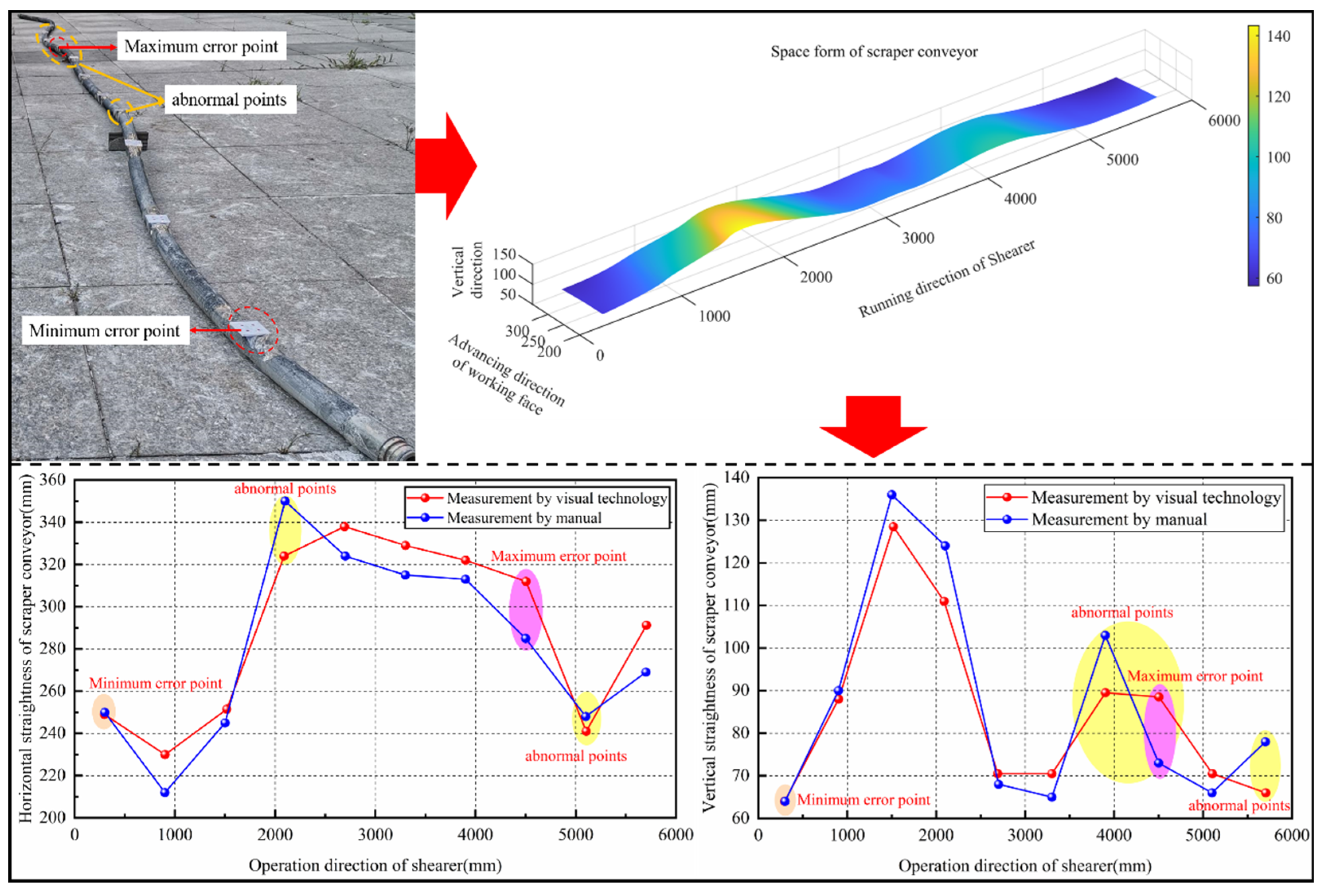
The visual joint measurement experimental model of the scraper conveyor was designed, the visual measurement test was carried out to obtain the spatial morphology of the scraper conveyor, and it was found that the minimum relative displacement between two adjacent middle chutes in the horizontal direction was 7 mm and the maximum relative displacement was 72.5 mm, and the minimum relative displacement between two adjacent middle chutes in the vertical direction was 0 and the maximum relative displacement was 40.5 mm.
(3)
The visual measurement and manual measurement results were compared and found to be in better agreement. Moreover, the visual measurement process is independent of each other, resulting in some points (anomalies) deviating from the real trajectory trend line of the scraper conveyor, indicating that the straightness measurement method of the scraper conveyor based on binocular vision in this paper has no error accumulation.
(4)
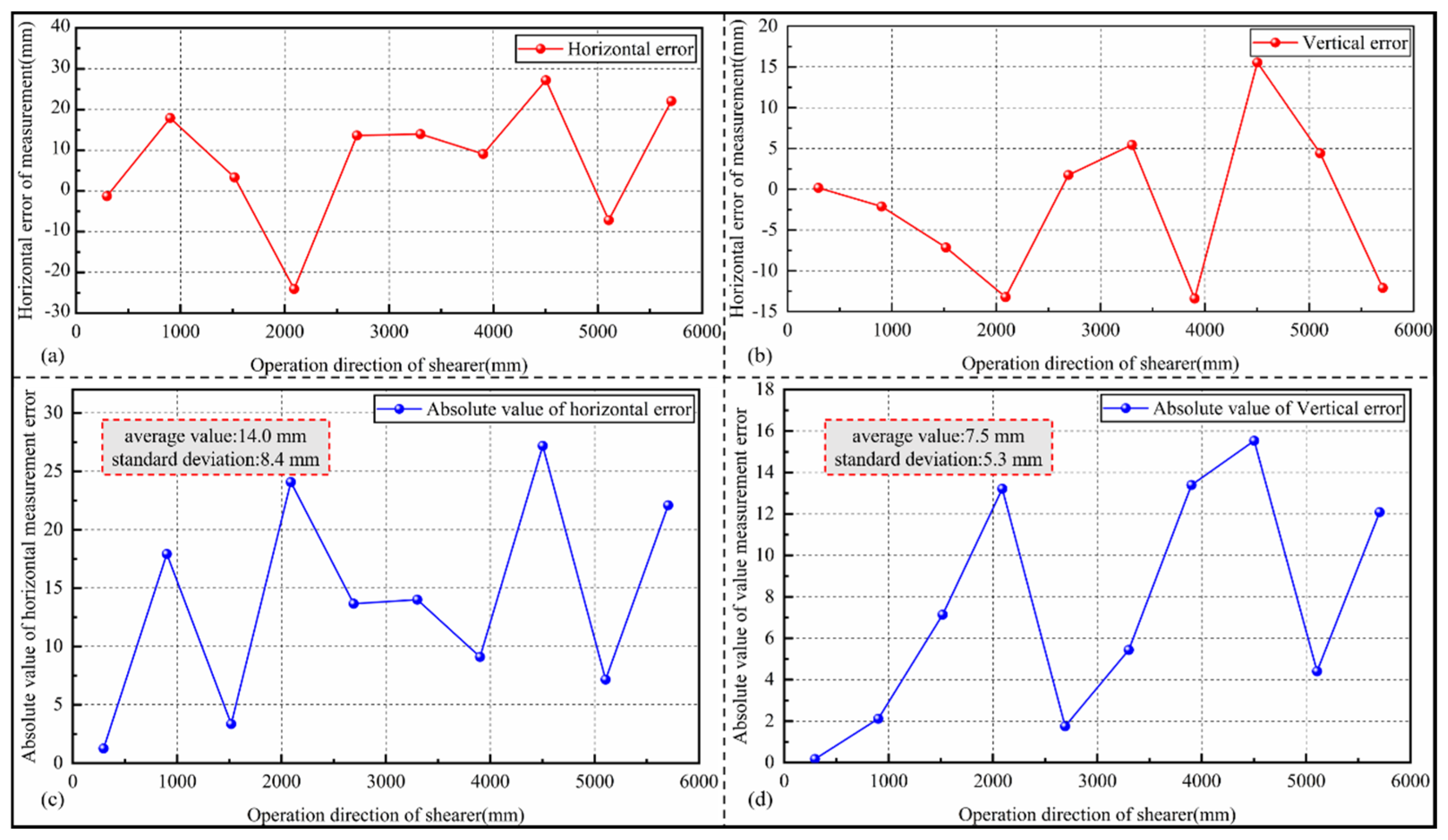
The visual measurement of scraper conveyor straightness error was analyzed, finding that the measurement error in both directions is within ±30 mm, which meets the requirement of ±50 mm for straightness accuracy of the coal face. Meanwhile, the standard deviations of the errors in the horizontal and vertical directions are small, 8.4 and 5.3, respectively, indicating that the straightness measurement method of the scraper conveyor based on binocular vision in this paper is highly reliable.

Author Contributions

Conceptualization, J.L., Z.W. and J.C.; Formal analysis, J.L. and K.X.; Investigation, J.L.; Methodology, J.L., P.S., Z.W. and J.C.; Project administration, Z.W.; Software, J.L., P.S., J.C., K.X. and H.G.; Supervision, Z.W. and J.C.; Validation, K.X. and H.G.; Visualization, P.S. and M.W.; Writing—original draft, J.L.; Writing—review & editing, Z.W. All authors have read and agreed to the published version of the manuscript.

Funding

This research was funded by [Jingyi Cheng] grant number [52274102] and The APC was funded by [the National Natural Science Foundation of China].

Conflicts of Interest

The authors declare no conflict of interest.

References

  1. Wang, G.F.; Du, Y.B. Coal mine intelligent standard system framework and construction ideas. J. China Coal Soc. 2020, 48, 1–9. [Google Scholar]
  2. Wang, G.F.; Du, Y.B.; Ren, H.W.; Fan, J.D.; Wu, Q.Y. Top level design and practice of smart coal mines. J. China Coal Soc. 2020, 45, 1909–1924. [Google Scholar]
  3. Fang, X.Q.; Liang, M.F.; Li, S.; Zhang, L.; Yan, H.B.; Xie, X.P.; Wei, R.; Wu, G.; Lv, J.K. Key technologies of multi-parameter accurate perception and security decision in intelligent working face. J. China Coal Soc. 2020, 45, 493–508. [Google Scholar]
  4. Fang, X.; Ning, Y.; Li, S.; Liang, M.F.; Wu, G.; Gu, C. Research on key technique of straightness perception of scraper conveyor based on fiber grating. Coal Sci. Technol. 2019, 47, 152–158. [Google Scholar]
  5. Liu, Q.X. Analysis on the Structural Performance of Sprocket of the SGZ1000 Scraper Conveyor. Mech. Manag. Dev. 2021, 36, 60–62. [Google Scholar]
  6. Xue, X.G. Analysis of Multiple Faults for Underground Scraper Conveyor and Its Prevention Strategy. Inn. Mong. Petrochem. Ind. 2021, 47, 76–77. [Google Scholar]
  7. Wang, R. Common Faults and Countermeasures of the Scraper Conveyor in Mines. Mech. Manag. Dev. 2021, 36, 290–292. [Google Scholar]
  8. Meng, G.Y.; Li, G.P.; Wo, L.; Wang, A.M. Intelligent Key Technologies of Complete Heavy Scraper Conveyor Equipment. Coal Sci. Technol. 2014, 42, 57–60. [Google Scholar]
  9. Kellym, S.; Hainsworthd, W.; Reid, D.C.; Caris, C.; Humphries, P.; Ralston, J.C.; Hargrave, C.O.; Gurgenci, H.; Li, F.; Poulsen, H.I.; et al. The Landmark Longwall Automation Project; ACARP Project, Report C10100A; ACARP: Brisbane, Australia, 2005. [Google Scholar]
  10. Hao, S.Q.; Wang, S.B.; Xie, G.J. Research of determination technologies of position and attitude of shearer on long-wall fully mechanized coal mining face. Ind. Mine Autom. 2014, 40, 21–25. [Google Scholar]
  11. Wang, S.B.; He, Y.; Wang, S.J.; Zhang, B.Y.; Ge, S.R. Study on the alignment method and experiment of scraper conveyor. J. China Coal Soc. 2017, 42, 3044–3050. [Google Scholar]
  12. Li, A.; Hao, S.Q.; Wang, S.B.; Ge, Z.; Ge, S. Experimental study on shearer positioning method based on SINS and Encoder. Coal Sci. Technol. 2016, 44, 95–100. [Google Scholar]
  13. Liu, P.K.; Wang, C. Straightness measurement algorithm based on machine vision for coal longwall face. J. Min. Sci. Technol. 2017, 2, 267–273. [Google Scholar]
  14. Yang, Z. Research on measurement technology of working face straightness based on vision measurement. Coal Eng. 2016, 48, 134–136. [Google Scholar]
  15. Jing, M. Optimization method of straightness error based on video measuring machine. J. Appl. Opt. 2016, 37, 419–424. [Google Scholar]
  16. Li, Y.H. A Study of Great Length Guide-Ways Straightness Vision Measurement; Xi’an University of Technology: Xi’an, China, 2009. [Google Scholar]
  17. Meng, Q.H.; Lin, C.Q.; Fan, D.X. Research on Machine Vision Principles and Applications. Autom. Appl. 2020, 4, 80–82. [Google Scholar]
  18. Zhang, Y.; Wang, B.P.; Fang, Y.; Song, Z. 3D Radar Imaging Method Based on Structured Sparse Reconstruction of Target Scene. J. Electron. Inf. Technol. 2021, 43, 1185–1191. [Google Scholar]
  19. Yang, W.J.; Zheng, L.X. Talking about Machine Vision. Mod. Comput. 2020, 30, 66–69+76. [Google Scholar]
  20. Luo, Y. The measurement method of dam deformation based on binocular stereovision. Electron. Test 2013, 19, 65–68. [Google Scholar]
  21. Zhao, N. Research and application of binocular stereo vision system. Electron. Technol. Softw. Eng. 2021, 5, 118–119. [Google Scholar]
  22. Zhu, F.; Yu, F.S.; Wu, Y.M.; Hao, C. P4P camera attitude calibration accuracy analysis. Acta Opt. Sin. 2018, 38, 241–249. [Google Scholar]
  23. Zhang, Z.J. Research on Technology of Position and Orientation Measurement for Vision Navigation Based on Coplanar Feature Points; PLA University of Information Engineering: Zhengzhou, China, 2013. [Google Scholar]
  24. Yang, J.H.; Liu, D.K.; Du, W.H.; Xing, L.N. Research on binocular ranging system based on image features. J. Syst. Simul. 2022, 34, 624–632. [Google Scholar]
  25. Xia, J.Y.; Xu, X.Q.; Xiong, J.L. Iterative pose estimation using paraperspective camera model. Opt. Precis. Eng. 2012, 20, 1342–1349. [Google Scholar]
  26. Ames, A. Visual perception and the rotating trapezoidal window. Psychol. Monogr. Gen. Appl. 1951, 65, i-32. [Google Scholar] [CrossRef]
  27. Chao, G.; Jiang, G.W.; Fu, S.H.; Yan, J. Software design and implementation of multi-camera transmission pose measurement system. Opto-Electron. Eng. 2011, 38, 8. [Google Scholar]
  28. Jiang, G.W. Study on Pose Relay Videometrics Method with Camera-Series and Ship Deformations Measurement; University of National Defense Science and Technology: Changsha, China, 2010. [Google Scholar]
  29. Lu, Y.; Wang, H.; Tong, W.; Junjie, L. Based on Harris-Zhang Zhengyou plane calibration method of camera calibration algorithm. J. Xi’an Univ. Archit. Technol. Nat. Ence Ed. 2014, 46, 860–864. [Google Scholar]
  30. Lu, P.P.; Liu, Q.; Guo, J.M. Camera Calibration Implementation Based on Zhang Zhengyou Plane Method. In Proceedings of the Chinese Intelligent Systems Conference (CISC), Yangzhou, China, 15–16 October 2015. [Google Scholar]
Figure 1. Pose acquisition model based on binocular vision 3D reconstruction.
Mathematics 10 03545 g001
Figure 2. Scraper conveyor visual contact force measurement method.
Mathematics 10 03545 g002
Figure 3. Visual measurement system with scraper conveyor straightness.
Mathematics 10 03545 g003
Figure 4. Scraper conveyor visual measurement experimental model.
Mathematics 10 03545 g004
Figure 5. Process of measuring straightness of scraper conveyor based on binocular vision.
Mathematics 10 03545 g005
Figure 6. Scraper conveyor straightness measurement results.
Mathematics 10 03545 g006
Figure 7. Visual measurement error diagram. (a) Relative error in horizontal direction; (b) Relative error in vertical direction; (c) Absolute value of error in horizontal direction; (d) Absolute value of error in vertical direction. From (a,b), it can be seen that the overall error of the scraper conveyor straightness measurement method based on binocular vision is within ±30 mm, which meets the requirement of ±50 mm for coal face straightening accuracy. In the horizontal direction, the maximum value of the visual measurement error is 27.2 mm, and the minimum value is −1.3 mm. In the vertical direction, the maximum value of the visual measurement error was 15.5 mm, and the minimum value was 0.2 mm. It was found that the error in the horizontal direction was generally larger than that in the vertical direction. To further analyze the error, the absolute value of the error is taken, as shown in (c,d).
Mathematics 10 03545 g007
Table 1. Information on the pose of scraper conveyor in each station.
Station NumberSign Board NumberRolling AnglePitch AngleAzimuth
11−18°28′28″
2−1°59′54″5°42′38″5°42′38″
23−1°59′44″6°0′32″18°28′58″
4−1°59′54″−7°59′28″17°31′32″
35−1°59′54″−3°8′15″
6−1°59′54″−3°8′15″
47−1°59′54″2°51′45″
8−1°59′54″−4°59′14″−18°28′28″
59−1°59′57″
10−1°59′50″−4°38′1″34°3′41″
Publisher’s Note: MDPI stays neutral with regard to jurisdictional claims in published maps and institutional affiliations.

