Article

Using Matlab/Simulink Software Package to Investigate Fault Behaviors in HVDC System

1
Department of Electrical and Electronics Engineering, Federal University Oye-Ekiti, P.M.B. 373, Km 3 Oye-Afao Road, Oye-Ekiti 370112, Ekiti State, Nigeria
2
Department of Nuclear and Renewable Energy, Ural Federal University Named after the First President of Russia Boris Yeltsin, 19 Mira Street, 620002 Ekaterinburg, Russia
3
Department of Electrical Engineering, College of Engineering, Jouf University, Sakaka 72388, Saudi Arabia
4
Department of Electrical Engineering, Faculty of Engineering, Aswan University, Aswan 81542, Egypt
*
Author to whom correspondence should be addressed.
Mathematics 2022, 10(16), 3014; https://doi.org/10.3390/math10163014
Submission received: 17 July 2022 / Revised: 15 August 2022 / Accepted: 19 August 2022 / Published: 21 August 2022
(This article belongs to the Special Issue Modeling and Simulation for the Electrical Power System)

Abstract

:
Existing studies show that several performance issues will arise in the HVDC link during the three phase-to-ground fault at the side of the inverter and that the DC voltage will oscillate around zero and will not affect the rectifier of the AC system though the inverter of the AC system, and the AC voltages will become zero and the AC currents will show high amplitude as well as minor disturbances. It has also been argued that when the fault is applied on a single-phase to ground fault at the inverter side on the AC side, the voltage will decrease. In this paper, we focus on single line-to-ground fault, double line-to-ground fault, and three phase-to-ground fault at the inverter of the AC system and their behavior on the DC link as well as on the AC system of the rectifier with detailed simulations. A high voltage direct current (HVDC) Monopolar system is modeled using a Matlab/Simulink software package for the research. The results show that during the three phase-to-ground fault at the AC system of the inverter, the DC voltage will increase with a bogus waveform and the currents of the AC system at the rectifier will collapse to zero.At the double phase-to-ground fault level, the DC voltage will experience an increase in waveform while the currents of the AC system of the rectifier will experience different disturbances. At the single phase-to-ground fault level, the DC voltage will remain stable and the rectifier side of the AC system will also experience a stable state for both currents and voltages.

1. Introduction

A number of research works have been carried out on the high voltage direct current (henceforth, HVDC) system. For example, Imani et al. [1] use the Intrinsic Time Decomposition (ITD) approach in an HVDC system, a non-communication-based protection (NCP) scheme. Their mission is to locate a problem in an HVDC line and also to evaluate the performance of the proposed approach against a variety of situations, including external disturbances such as AC line fault and rapid changes in active power.In addition, they confirm that defect detection and classification from the scheme can be completed in less than 1 millisecond. Simulink/Matlab with PSCAD/ EMTDC environment is used to simulate the system and results are carried out along with the energy index called Teager Kaiser Energy Operator which is used to compute and input signals. Singh et al. [2] believe that understanding fault characteristics is necessary in order to isolate the defective parts. In their study, AC side defects such as SLG, LLG, and LLLG fault along with line-to-line and line-to-ground faults on the HVDC side are also examined. The PSCAD/EMTDC–Simulink model are used in their work to illustrate the various fault characteristics. Londhe et al. [3] develop a fault detection system for the HVDC transmission line using the Bayesian regularization neural network.A model of the HVDC transmission line is designed to obtain information on both healthy and defective circumstances.In their further study, line-to-line and double line-to-ground faults for the DC link are taken into consideration. AC side faults such as triple-line-to-ground, double-line-to-ground, line-to-ground, line-to-line, and triple-line faults at the converter side are also discussed. The results are obtained in Matlab/Simulink. Merlin et al. [4] suggest a technique for identifying and classifying defects in HVDC systems based on an Artificial Neural Network. In their result, they are able to identify and categorize faults in any point of the system including the rectifier substation, inverter substation, and in the DC line using just a voltage signal spectrum (VSS). Chen et al. [5] propose a fault identification method for HVDC transmission line based on KNN and t-SNE.They prove that it can accurately realize internal and external fault identification as well as fault pole selection. In addition, they confirm that the method can address the low accuracy of HVDC transmission line protection for remote highresistance and also believe that it has a good anti-interference ability and a great ability to handle transition resistance.
Furthermore, Khairnar et al. [6] observe that the pole-to-ground fault is seen to be the most frequent fault and it can cause a significant over-current in the AC grid resulting in the damage of converter valves. They also detect that the rectifier station has a greater impact than the inverter station when a fault occurs. The PSCAD software is used to carry out the simulation. Hameurlaine et al. [7] address several performance issues that may arise in the HVDC link. In their results, during the three phase-to-ground fault at the side of the inverter, the DC voltage will oscillate around zero (0) due to the commutation failure (CF) on the inverter side. Furthermore, they confirm that the fault will not affect the rectifier of the AC system but the inverter of the AC system and the AC voltages will become zero and AC currents will show a high amplitude fault and minor disturbances. Malik and Modi [8] also investigate the fault analysis for the HVDC transmission line. In their research, they investigate how the system reacts to various types of malfunctions which help them to distinguish the AC and DC fault. All the simulations are carried out in Matlab. Karthikeyan et al. [9] also study different fault characteristics of the AC system. Various fault simulations including single, two, three phase-to-ground, and DC line-to-line faults are carried out in different places of the test system in their simulation. The DC transmission system’s transient reaction under disturbance is then compared with that of the AC system. They also look at the rate of change of the transient DC current and conclude that the quickest transient is caused by a DC fault while the slowest transient is caused by a load shift. Dessouky et al. [10] focus on DC pole-to-pole which is among the most harmful defects in the system and fault behavior is carried out using Matlab-Simulink.
In addition, Roy [11] similarly focuses on detecting the types of problems and their locations. Both the AC grid and the DC transmission lines are used to simulate the faults. On the AC grid, short circuit shunt faults are simulated for various fault resistances, fault inception times, and short circuit ratios (SCR). The faults are properly classified in all cases, and the locations of DC line-to-ground (DCLG) fault are determined with convincing precision. All the simulations are carried out using the MATLAB software. Muzzammel [12] suggests that it is necessary to anticipate or identify any abnormalities in HVDC systems. In the findings, it is confirmed that machine learning is a method of extracting information from data without having to program it explicitly. A fault diagnostic technique based on machine learning is created and Matlab/Simulink is used to carry out the simulations.Johnson and Yadav [13] carry out a simple accurate method for defect location in HVDC transmission lines using Artificial Neural Networks. The HVDC system is modeled in PSCAD/EMTDC but further research is carried out in the Matlab environment. Their study is on fault location in AC RMS voltage and DC line voltage and current, but Johnson and Yadav [14] use K-nearest neighbors in their study. Saleem et al. [15] present a fault detection and classification in HVDC transmission lines with the help of the Discrete Wavelet Transform. In their paper, the proposed method is successfully tested for a variety of fault types at various line locations. In the end, MATLAB/Simulink is used to acquire the details. Agarwal et al. [16] claim that fault detection is critical for the transmission line. In their paper, they calculate the THD when the model is simulated and examined using FFT. After the results, they suggest that the proposed method is capable of detecting faults. Muzzammel and Raza [17] discover that a lot of research has been done to develop new approaches and existing techniques based on speed and accuracy in order to prevent the negative effects of a fast surge in DC fault current. They prove that machine learning is extremely useful for classification and location of faults. In their work, Matlab/Simulink is employed to simulate the model.
Still on previous studies, Usman et al. [18] confirm that power transmission experiences numerous problems because of expansion, increase in population, urbanization, and environmental concerns. Their goal is to identify any abnormal behavior on the AC and DC sides and determine the time required for restoring the system to its reliable state settings and MATLAB/SIMULINK is used to carry out the analysis. Salem et al. [19], in their findings, discover that most common forms of HVDC faults are DC pole-to-pole and DC pole-to-ground faults.The authors use extensive mathematical and theoretical approaches for the stages of the faults. A comprehensive simulation result based on Matlab–Simulink software is undertaken to verify this assignment. Melo et al. [20] examine a new method for detecting problems in transmission lines in HVDC systems. The proposed method makes an advantage of synchronized voltage and current data. The approach for detecting defects in transmission lines employs a self-adaptive threshold and includes redundancy, allowing fault identification even when either the voltage or current signal is lost. Simulink/MATLAB® is used to simulate the system and results are carried out. Singh and Ukil [21] have also shown that electrical energy consumption has risen dramatically in recent years as a result of its use for commercial, industrial, household, social, and agricultural purposes. Because of its advantages, HVDC technology is rapidly being adopted for bulk power transmission. They therefore employ the PSCAD to simulate various types of failures in HVDC transmission lines, but the MATLAB software is used to examine the generated fault signals. The most interesting part is that fault detection in an HVDC system must be quick and precise. They indicate in their study that the S-transform may successfully detect the transient signal. According to them, it may be used to distinguish between different types of defects as well as load variations. Naveen et al. [22] present faults on the HVDC Monopolar transmission line such as the performance of the converter, DC faults (voltage and current), and a line-to-ground fault on the AC side. They use the Matlab/Simulink environment to model and simulate.In their results, it shows that during faulty conditions, the AC voltages waveforms have a slight decrease, and AC currents decrease from their expected value. An overview of previous literature with respect to their strengths and weaknesses ispresented in Table 1. Some of the conclusions that can be drawn from the previous studies are: first, it has been shown that several performance issues may arise in the HVDC link during the three phase-to-ground fault at the side of the inverter and that the DC voltage will oscillate around zero and will not affect the rectifier of the AC system, though the inverter of the AC system and the AC voltages will become zero and AC currents will show high amplitude as well as minor disturbances. Second, it has been argued that when the fault is applied on a single-phase to ground fault at the inverter side on the AC side, the voltage will decrease. In this paper, we focus on a single line-to-ground fault, double line-to-ground fault, three phase-to-ground fault at the inverter of the AC system, and their behavior on the DC link as well as on the AC system of the rectifier with detailed simulations. A high voltage direct current (HVDC) Monopolar system is modeled using Matlab/Simulink software package for the research. The paper has four sections. The introduction is presented in Section 1 and materials and methods are discussed in Section 2. The proposed model appears in Section 3, results and discussion are considered in Section 4, and the conclusion is presented in Section 5.

2. Materials and Methods

In this section, we discuss materials and methods which include synchronous machine, converter transformer, three-phase graetz bridge rectifier, Mosfet, and DC filter. The discussion is presented below.

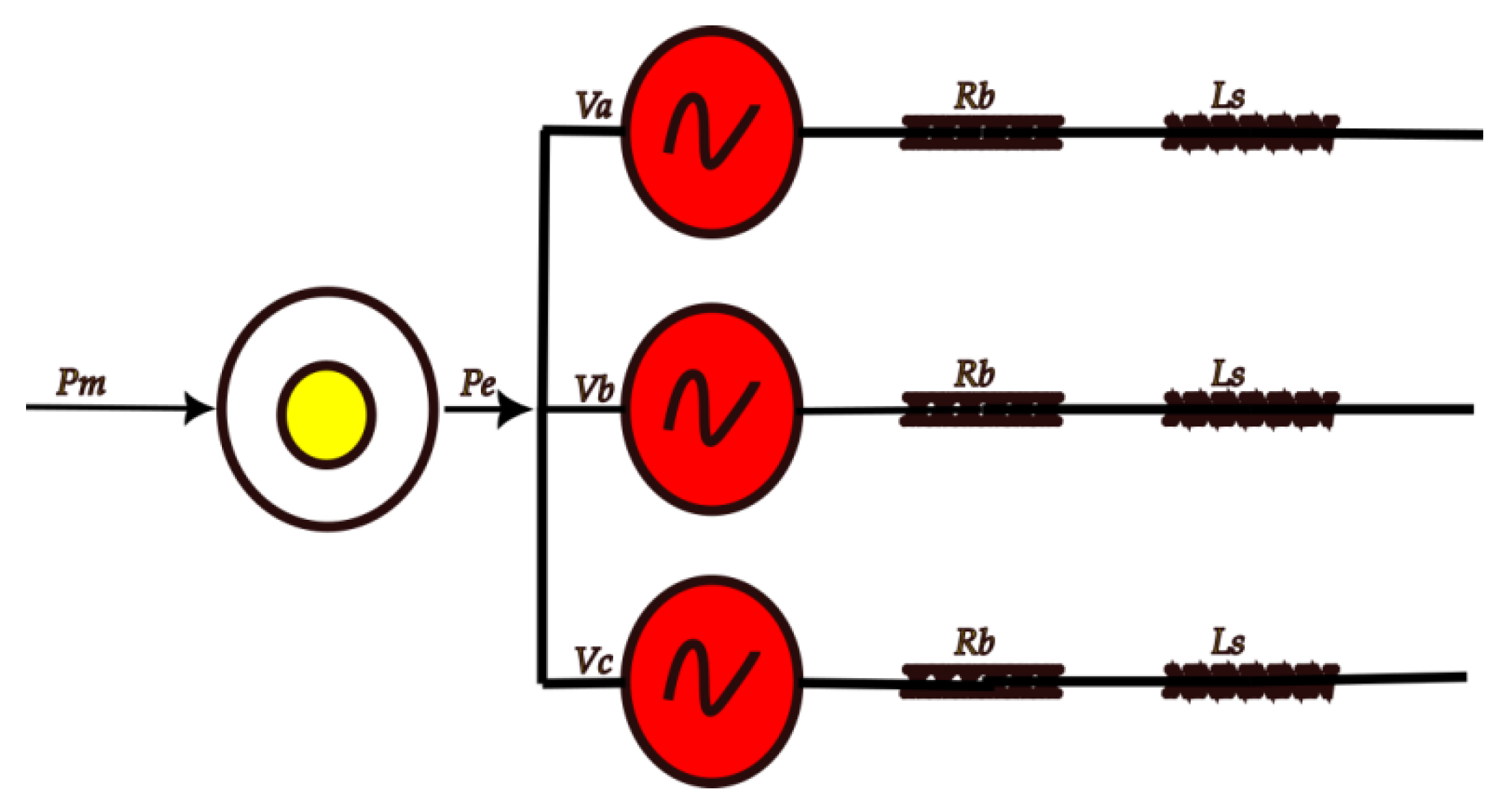
2.1. Synchronous Machine

Synchronous machines are an important source of energy in electrical power networks and are frequently used as generators. The rotor and stator are the machine’s main mechanical parts. Additionally, the machine’s magnetic fields and currents interact to create a torque that slows down the rotor. A generator or a motor is created as a result of these two processes which convert mechanical energy to electromagnetic energy. At a steady state the rotor speed is proportional to the frequency of voltages and currents in the stator [23]. Power systems have used synchronous machines widely; they serve as both the main power generators in large conventional power plants and the remote stand-alone systems. Several new types of synchronous generators, including multi-pole machines for wind power conversion systems, are being developed for rapidly emerging renewable and distributed generation (DG) systems. With the aid of this equipment, a high efficiency, dependable power system with good power quality can be achieved [24]. The mathematical formulas are given below.
ϑ = p m 2 ϑ m
where,
ϑ : The rotor electrical angle
ϑ m : The rotor mechanical angle
p m : The number of magnetic poles on the rotor
In addition, frequencies are defined as follows:
f r e = θ t : The rotor electrical frequency;
f r m = ϑ m t : Rotor mechanical frequency;
f g : Represents the grid frequency, for example:
f g = 2 π 50   o r   2 π 60   rad / s  
Following Equation (1) we have,
f r e = p m 2 f r m
The frequencies are typically measured in rad/s,
The angular acceleration of the rotor is given by
t f r m = 1 J ( T m r T e d r )
where,
J :   Represents the rotor moment of inertia
T m r : Represents the mechanical torque, accelerating the rotor
T e d r : Representing the electromagnetic torque
In addition, the power can be expressed as
p m e c a c c = T m r f r m = 2 p m T m r f r e p e l e c d e c = T e d r f r m = 2 p m T e d r f r e
where
p m e c a c c :   Represents the mechanical power
p e l e c d e c : Represents the electromagnetic power
So, the Equations(2) and (3):
t f r e = p m 2 J ( T m r T e d r )
The following Equations (4) and (5) have
t f r e = ( p m 2 ) 2 1 J f r e ( p m e c a c c p e l e c d e c ) = K f g f r e ( p m e c a c c p e l e c d e c )
where K = ( p m 2 ) 2 1 J f g .
It is also assumed that the mechanical torque is governed by a droop mechanism which is expressed as
T m r = p m 2 f g ( 3 P r e f 1 D ( f r e f g ) )
where
D : Represents the damping coefficient
P r e f : Represents the reference power
The flow of power in the machine is summarized in Figure 1.

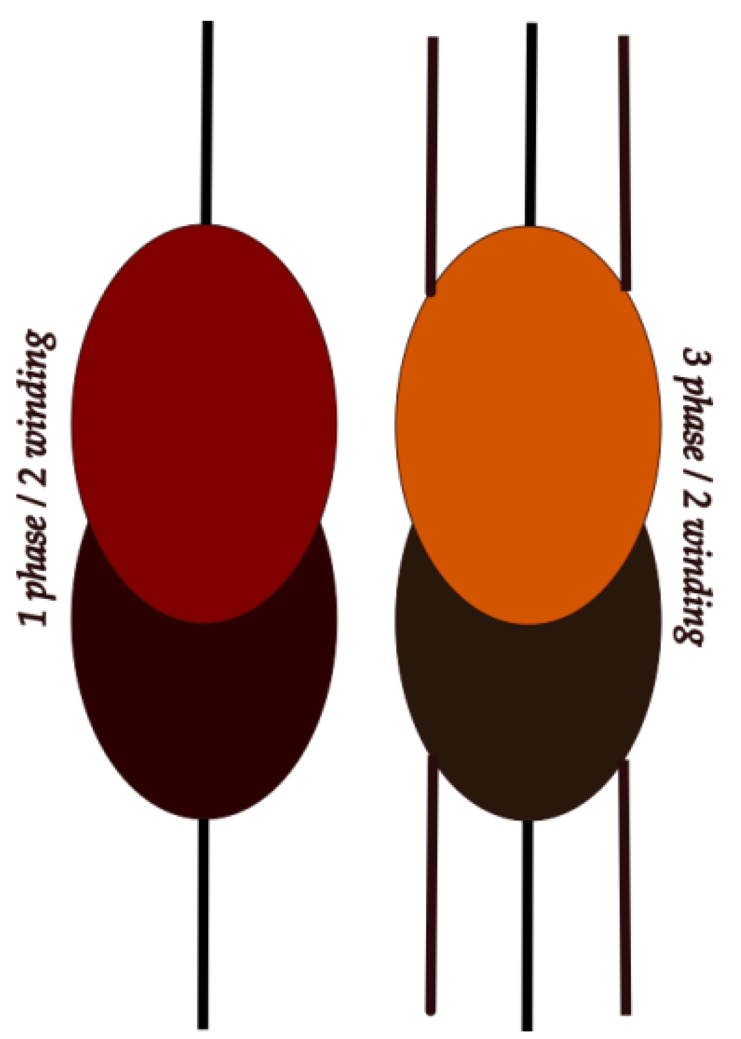
2.2. Converter Transformer

Transformer is a passive component (PC) thattransferselectrical energy from one electrical circuit (EC) to another and is also used to adjust the AC voltage levels; these transformers are classified as step-down or step-up type to decrease or increase the voltage level. The transformer is positioned in the middle to connect the universal bridge to the AC networks at both ends. The converter transformer is by far the most important part. The converter transformer can be used in either the three-phase system or the single-phase layout. However, the one-phase/two winding transformer and three-phase/two winding transformer, as shown in Figure 2, are both acceptable model conformations for the converter banks [25].

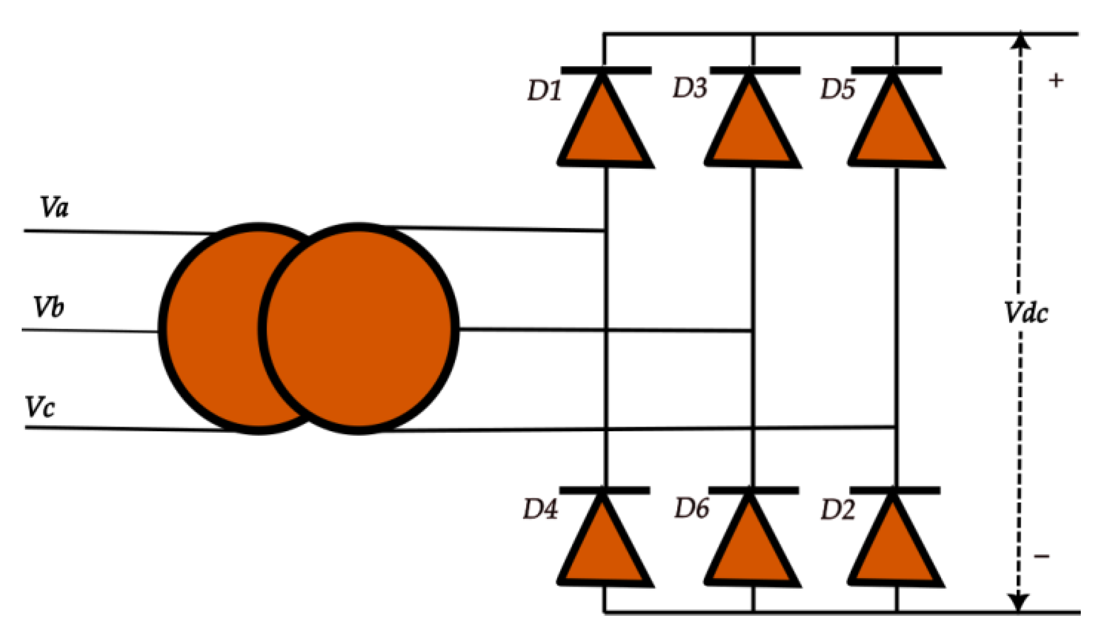
2.3. Three-Phase Graetz Bridge Rectifier

A voltage source is necessary for the standard line commutated converter of the diode valves to verify commutation. Commutation, with relation to the diode valve, is the transfer of current from one phase to another. The Graetz Bridge serves as the cornerstone for the three phases. The current Id passes through the diodes of D1, D3, and D5 (at the up group) and D2, D4, and D6 (at the down group) throughout execution [26]. One diode to the next will naturally experience current flow. The diagram of the three phase 6 pulse bridge rectifier is shown in Figure 3. Let us consider that the rectifier is provided from a three-phase voltage system. The mathematical formula is expressed as given in the equation
V 1 = V m cos ( w 0 t )
V 2 = V m cos ( w 0 t 2 p i 3 )
V 3 = V m cos ( w 0 t 4 p i 3 )
The amplitude V m of the three-phase voltage equals
V m = V p ( r m s ) 2
where
V p ( r m s ) : is the root mean square value
The DC output voltage
V o u t = 3 3 p i V m
For the input current, I r m s the formula can be expressed as
I r m s = 6 3 I o u t
The power output of the rectifier output, P o u t
P o u t = V o u t I o u t = 3 3 p i V m I o u t = P i n

2.4. Mosfet

A voltage-controlled field effect transistor is a MOSFET. It contains a “Metal Oxide” Gate electrode that is separated electrically from the primary semiconductor n-channel or p-channel by a very thin layer of insulating material, often silicon dioxide, also known as glass. This extremely thin insulated metal gate electrode can be compared to a capacitor’s base plate. The input resistance of the MOSFET is so high, up in the Mega-ohms (M) range, due to the isolation of the regulating Gate, that it is practically unlimited.
The MOSFET also performs the function of a voltage-controlled resistor, where the input voltage determines how much current flows through the main channel between the drain and source. If not handled carefully or protected, the MOSFET can easily become damaged due to its extremely high input resistance, which allows enormous amounts of static charge to collect. In addition, due to its quick switching time, low gate drive power, and ability to sustain simultaneous high current and voltage applications without experiencing any destructive failure, MOSFET is one of the most widely used power devices [27].

2.5. DC Filter

2.5.1. Capacitor

A stable DC voltage with a little ripple is what the HVDC system is concerned with at the transmission line. Therefore, a DC capacitor placed across the converter station can eliminate this ripple and produce a steady DC voltage. To maintain a reliable steady-state performance when the system is disrupted by a disturbance, the capacitor’s capacity should not be too large.

2.5.2. Smoothing Reactor

The DC voltage and current fluctuations are lessened, and the DC current rising speed is suppressed [28].

3. Proposed HVDC Monopolar System

The parameters of the system description are given below in the following subsections.

3.1. Synchronous Machine

For the synchronous machine (generator) design at the sending end, the parameters are: three-phase phase apparent power = 100 MVA; line-to-line voltage = 25 kV; frequency = 60 Hz; Stator resistance = 2.8544 × 10⁻³.

3.2. Transformer

The parameters for the transformer are: the nominal power (VA) = 50 kVA; nominal frequency = 60 Hz; phase to phase (L-L) nominal voltage = 600 V; the resistance and leakage inductance = 0.002 & 0.08.

3.3. Three-Phase Load

The inverter end parameters of the load are: nominal phase to phase (L-L) voltage = 440 V; nominal frequency = 50 Hz; Active power = 5 × 10³ W. The model for the HVDC monopolar system is as shown in Figure 4.

4. Results and Discussion

We looked into the behavior of the HVDC network in a variety of operational conditions, such as AC network faults. Different fault circumstances were imposed on the network from the receiving end in order to evaluate the system’s performance and the effects of the imposed AC line faults. We ran simulations in the Matlab/Simulink environment in order to categorize the fault situations of the system. An AC line failure at the receiving end was used in this scenario.
When a three phase-to-ground (LLLG) fault develops on the receiving end of the load at 0.2 s, the AC grid voltages of phase A, phase B, and phase C will reduce to zero. This is shown in Figure 5a. It will also be observed that the magnitude of the AC grid currents will show rise in sinusoidal waveforms higher than the normal values shown in Figure 5b. The DC line voltage will rapidly increase, resulting in an oscillation waveform shown in Figure 5c. During the fault, the rectifier end, the AC grid voltages will result in a slight increase in magnitude, which is shown in Figure 5d, while the magnitude of the AC grid currents of phase A, phase B, and phase C will result in zero values, shown in Figure 5e. After the fault, the system will return to the normal state of 0.62 s. At 0.2 s, the double phase-to-ground (LLG) fault will occur at the receiving end of the load. The AC grid voltages of phase A and phase C will rapidly drop to zero while the phase B will experience an increase in voltage shown in Figure 6a, and the AC currents of pole A and pole C will result in a rise in magnitude which is higher than the original values; but the phase B will maintain a steady state waveform, and this is shown in Figure 6b. The DC line voltage will show a false waveform shown in Figure 6c. At the sending end, AC grid voltages will have slight increase in values with slight disturbances and the AC grid currents will have clear results of different distortions which are shown in Figure 6d,e. At the inverter end of the load, a single line-to-ground (LG) fault occurs. The voltage magnitude of pole C will collapse to zero at 0.2 s (0.4–0.6) while the other poles of A & B will shoot up in voltages shown in Figure 7a and the current of phase A, phase B, and phase C will appear to be normal as shown in Figure 7b. The DC voltage will maintain a stable state which is shown in Figure 7c. At the rectifier end of the source, the AC voltages and currents will display normal standard values which are shown in Figure 7d,e. After the fault of 0.2 s, the system will become balanced.

5. Conclusions

Single line-to-ground fault, double line-to-ground fault, and three phase-to-ground fault at the inverter of the AC system and their behavior on the DC link as well as on the AC system of the rectifier with detailed simulations are carried out in this paper. A high voltage direct current (HVDC) Monopolar system is modeled using a Matlab/Simulink software package for the research. It is noticed that the three phase-to-ground fault at the AC system of the inverter will result in aslight increase in AC voltages and the currents will drop significantly to zero at the rectifier side. It is also submitted that the AC voltages will increase in magnitude and the currents will have different surge distortions during the double phase-to-ground fault at the receiving end and that the single line to ground fault will show no effect at the rectifier side during the standard conditions. For the DC transmission line behavior, during the three phase-to-ground fault at the inverter side the DC voltage will rise with a bogus waveform and the result of the DC voltage during a double phase-to-ground fault will be less than the DC voltage during an LLLG fault with a false sinusoidal waveform, while the behavior of the DC voltage during the single line to ground fault will show a balanced state with no effect.
Furthermore, at the inverter side of the three-phase AC system where the fault is applied, the result shows that the AC voltages will reduce to zero and the AC currents will rise in sinusoidal waveforms higher than the normal values during the three phase-to-ground fault. During the double phase-to-ground fault, the AC voltages of phases where the fault is applied will rapidly drop to zero while the other will experience increase in voltage, and the AC currents of the affected poles will result in a rise in magnitude which is higher than the original values as the other phase will maintain a steady state waveform. It has been shown also that during the single phase-to-ground fault at the inverter, the voltage magnitude of the affected will collapse to zero while the other poles will shoot up in voltages and the currents of phases will appear to be normal. One question that has not been addressed in this paper is: Can we still have the same results if any other software is used? The answer to this question can be the focus of another paper.

Author Contributions

Conceptualization, O.I.; methodology, O.I. and E.B.A.; software, O.I., E.B.A. and S.K.; validation, O.I., E.B.A., S.K. and EMA; formal analysis, O.I., E.B.A., S.K. and E.M.A.; investigation, O.I., E.B.A., S.K. and E.M.A.; resources, O.I., E.B.A., S.K. and E.M.A.; data curation, O.I., E.B.A., S.K. and E.M.A.; writing—original draft preparation, O.I.; writing—review and editing, O.I., E.B.A., S.K. and E.M.A.; visualization, O.I.; project administration, O.I.; funding acquisition, S.K. and E.M.A. All authors have read and agreed to the published version of the manuscript.

Funding

The research funding from the Ministry of Science and Higher Education of the Russian Federation (Ural Federal University Program of Development within the Priority-2030 Program) is gratefully acknowledged. Grant number: FEUZ–2022-0031.

Institutional Review Board Statement

Not applicable.

Informed Consent Statement

Not applicable.

Data Availability Statement

Not applicable.

Conflicts of Interest

The authors declare no conflict of interest.

References

  1. Imani, A.; Moravej, Z.; Pazoki, M. A novel time-domain method for fault detection and classification in VSC-HVDC transmission lines. Int. J. Electr. Power Energy Syst. 2022, 140, 108056. [Google Scholar] [CrossRef]
  2. Singh, D.; Saxena, D.; Chauhan, R.K. Analysis of the Impact of AC Faults and DC Faults on the HVDC Transmission Line. In Machine Learning, Advances in Computing, Renewable Energy and Communication; Springer: Singapore, 2022; pp. 123–136. [Google Scholar]
  3. Londhe, A.S.; Ingale, A.S.; Khadse, C.B. Bayesian Regularization Neural Network-Based Fault Detection System in HVDC Transmission System. In Smart Technologies for Energy, Environment and Sustainable Development; Springer: Singapore, 2022; Volume 1, pp. 601–607. [Google Scholar]
  4. Merlin, V.L.; dos Santos, R.C.; Pavani, A.P.; Vieira, J.C. A frequency spectrum-based method for detecting and classifying faults in HVDC systems. Electr. Power Syst. Res. 2022, 207, 107828. [Google Scholar] [CrossRef]
  5. Chen, L.; Wu, H.; Yang, Y.; Li, D. Fault Identification Method of HVDC Transmission Line based on t-SNE. Int. Core J. Eng. 2022, 8, 222–236. [Google Scholar]
  6. Khairnar, S.K.; Hadpe, S.S.; Shriwastava, R.G.; Khule, S.S. Fault Detection and Diagnosis of Monopolar Configured VSC Based High Voltage Direct Current Transmission Line. Glob. Transit. Proc. 2022, 3, 43–54. [Google Scholar] [CrossRef]
  7. Hameurlaine, A.; Sayah, H.; Boukezzi, L. Design of Protection Strategies and Performance Analysis of an HVDC Link During Multiple Disturbances. Eng. Technol. Appl. Sci. Res. 2022, 12, 8760–8764. [Google Scholar] [CrossRef]
  8. Malik, M.; Modi, S. HVDC Transmission Line Faults Analysis. Int. J. Eng. Res. Technol. 2020, 8. [Google Scholar] [CrossRef]
  9. Karthikeyan, M.; Yeap, Y.M.; Ukil, A. Simulation and Analysis of Faults in High Voltage DC (HVDC) Power Transmission. In Proceedings of the IECON 2014—40th Annual Conference of the IEEE Industrial Electronics Society, Dallas, TX, USA, 29 October–1 November 2014; pp. 1786–1791. [Google Scholar]
  10. Dessouky, S.S.; Fawzi, M.; Ibrahim, H.A.; Ibrahim, N.F. DC Pole to Pole Short Circuit Fault Analysis in VSC-HVDC Transmission System. In Proceedings of the 2018 Twentieth International Middle East Power Systems Conference (MEPCON), Cairo, Egypt, 18–20 December 2018; pp. 900–904. [Google Scholar]
  11. Roy, N.B. Fault Identification and Determination of Its Location in a HVDC System Based on Feature Extraction and Artificial Neural Network. J. Inst. Eng. India Ser. B 2021, 102, 351–361. [Google Scholar] [CrossRef]
  12. Muzzammel, R. Machine Learning Based Fault Diagnosis in HVDC Transmission Lines. In Intelligent Technologies and Applications; Bajwa, I.S., Kamareddine, F., Costa, A., Eds.; Communications in Computer and Information Science; Springer: Singapore, 2019; Volume 932, pp. 496–510. ISBN 9789811360510. [Google Scholar]
  13. Johnson, J.M.; Yadav, A. Fault Location Estimation in HVDC Transmission Line Using ANN. In Proceedings of First International Conference on Information and Communication Technology for Intelligent Systems: Volume 1; Satapathy, S.C., Das, S., Eds.; Smart Innovation, Systems and Technologies; Springer International Publishing: Cham, Switzerland, 2016; Volume 50, pp. 205–211. ISBN 978-3-319-30932-3. [Google Scholar]
  14. Johnson, J.M.; Yadav, A. Fault Detection and Classification Technique for HVDC Transmission Lines Using KNN. In Information and Communication Technology for Sustainable Development; Mishra, D.K., Nayak, M.K., Joshi, A., Eds.; Lecture Notes in Networks and Systems; Springer: Singapore, 2018; Volume 10, pp. 245–253. ISBN 978-981-10-3919-5. [Google Scholar]
  15. Saleem, U.; Arshad, U.; Masood, B.; Gul, T.; Khan, W.A.; Ellahi, M. Faults Detection and Classification of HVDC Transmission Lines of Using Discrete Wavelet Transform. In Proceedings of the 2018 International Conference on Engineering and Emerging Technologies (ICEET), Lahore, Pakistan, 22–23 February 2018; pp. 1–6. [Google Scholar]
  16. Agarwal, S.; Singh, R.K.; Verma, V. Fault Detection Using Harmonic Analysis of Single Terminal DC Current Signal of HVDC Line. In Advances in Smart Grid Automation and Industry 4.0; Reddy, M.J.B., Mohanta, D.K., Kumar, D., Ghosh, D., Eds.; Lecture Notes in Electrical Engineering; Springer: Singapore, 2021; Volume 693, pp. 631–638. ISBN 9789811576744. [Google Scholar]
  17. Muzzammel, R.; Raza, A. Fault Classification and Location in MT-HVDC Systems Based on Machine Learning. In Artificial Intelligence Applications in Electrical Transmission and Distribution Systems Protection; CRC Press: Boca Raton, FL, USA, 2021; pp. 453–479. [Google Scholar]
  18. Usman, A.M.; Kutay, M.; Ercan, T. MATLAB/SIMULINK Model for HVDC Fault Calculations. In Proceedings of the 2019 International Aegean Conference on Electrical Machines and Power Electronics (ACEMP) & 2019 International Conference on Optimization of Electrical and Electronic Equipment (OPTIM), Istanbul, Turkey, 27–29 August 2019; pp. 493–499. [Google Scholar]
  19. Salem, A.A.; Ewada, A.M.; Abdelsalam, A.A. Modeling and Performance Analysis of VSC-HVDC Transmission System with DC Side Line to Line Fault. In Proceedings of the 2021 22nd International Middle East Power Systems Conference (MEPCON), Assiut, Egypt, 14–16 December 2021; pp. 326–332. [Google Scholar]
  20. Melo, Y.; Neves, W.; Fernandes, D. Fault detection and localization for HVDC transmission lines. In Proceedings of the 2018 Simposio Brasileiro de Sistemas Eletricos (SBSE), Niteroi, Brazil, 12–16 May 2018; pp. 1–5. [Google Scholar]
  21. Singh, K.; Ukil, A. Fault Detection in HVDC Transmission Line by S-Transform Technique. In Proceedings of the 2019 IEEE PES Asia-Pacific Power and Energy Engineering Conference (APPEEC), Macao, China, 1–4 December 2019; pp. 1–5. [Google Scholar]
  22. Gaur, N.; Mahela, O.P.; Mahia, R.N. Analysis of faults on Monopolar hvdc transmission line. Int. J. Electr. Electron. Eng. (IJEEE) 2014, 4, 11–18. [Google Scholar]
  23. Levron, Y.; Belikov, J.; Baimel, D. A tutorial on dynamics and control of power systems with distributed and renewable energy sources based on the DQ0 transformation. Appl. Sci. 2018, 8, 1661. [Google Scholar] [CrossRef] [Green Version]
  24. Chen, Z.; Blaabjerg, F.; Iov, F. A Study of Synchronous Machine Model Implementations in Matlab/Simulink Simulations for New and Renewable Energy Systems. In Proceedings of the 2005 International Conference on Electrical Machines and Systems, Nanjing, China, 27–29 September 2005; Volume 3, pp. 1960–1965. [Google Scholar]
  25. Carlson, A.; Sweden, L. Specific Requirements on HVDC Converter Transformers; ABB Transformers AB: Ludvika, Sweden, 1996; pp. 1–4. [Google Scholar]
  26. Gnanarathna, U.N.; Gole, A.M.; Jayasinghe, R.P. Efficient Modeling of Modular Multilevel HVDC Converters (MMC) on Electromagnetic Transient Simulation Programs. IEEE Trans. Power Deliv. 2011, 26, 316–324. [Google Scholar] [CrossRef] [Green Version]
  27. Langpoklakpam, C.; Liu, A.C.; Chu, K.H.; Hsu, L.H.; Lee, W.C.; Chen, S.C.; Sun, C.W.; Shih, M.H.; Lee, K.Y.; Kuo, H.C. Review of Silicon Carbide Processing for Power MOSFET. Crystals 2022, 12, 245. [Google Scholar] [CrossRef]
  28. Lu, Q.; Sun, Y.; Mei, S. Nonlinear Control Systems and Power System Dynamics; Springer: Berlin/Heidelberg, Germany, 2013. [Google Scholar]
Figure 1. Synchronous Machine model.
Mathematics 10 03014 g001
Figure 2. The transformer types.
Mathematics 10 03014 g002
Figure 3. Three-phase bridge rectifier.
Mathematics 10 03014 g003
Figure 4. Model of HVDC Monopolar system.
Mathematics 10 03014 g004
Figure 5. Simulation results for HVDC system during a three phase-to-ground (LLLG) fault at station 2. (a) Three-phase AC voltages at the inverter side. (b) Three-phase AC currents at the inverter side. (c) DC line voltage. (d) Three-phase AC voltages at the rectifier side. (e) Three-phase AC currents at the rectifier side.
Mathematics 10 03014 g005aMathematics 10 03014 g005b
Figure 6. During a double phase-to-ground fault at station 2, simulation results for the HVDC system were obtained. (a) Three-phase AC voltages at the inverter side. (b) Three-phase AC currents at the inverter side. (c) DC line voltage. (d) Three-phase AC voltages at the rectifier side. (e) Three-phase AC currents at the rectifier side.
Mathematics 10 03014 g006aMathematics 10 03014 g006b
Figure 7. Simulation findings for the HVDC system were achieved during a single phase-to-ground (LG) fault. (a) Three-phase AC voltages at the inverter side. (b) Three-phase AC currents at the inverter side. (c) DC line voltage. (d) Three-phase AC voltages at the rectifier side. (e) Three-phase AC currents at the rectifier side.
Mathematics 10 03014 g007aMathematics 10 03014 g007bMathematics 10 03014 g007c
Table 1. Overview of the Literature review.
No.Ref.TitleStrengthWeakness
1Imani et al. [1] A novel time-domain method for fault detection and classification in VSC-HVDC transmission linesThe fault is detected within 0.8 ms after occurrence and then, the faulty pole is determined. The proposed scheme is able to detect high resistance fault up to 100 Ω. The ITD algorithm leads to low computational burden and achieve effective fault detection index. In contrast to the most of non-unit protection schemes, the selectivity of the proposed scheme is examined and verified.The results show that during the three phase-to-ground fault at the AC system of the inverter, the currents of the AC system at the rectifier will collapse to zero. At the double phase-to-ground fault level, the currents of the AC system of the rectifier will experience a difference. The results show that during the three phase-to-ground fault at the AC system of the inverter, the currents of the AC system at the rectifier will collapse to zero. At the double phase-to-ground fault level, the currents of the AC system of the rectifier will experience different disturbances. At the single phase-to-ground fault level, the rectifier side of the AC system will also experience a stable state for both currents and voltages
2Singh et al. [2]Analysis of the Impact of AC Faults and DC Faults on the HVDC Transmission LineFrom the simulation result, we can see that DC faults have the highest current and therefore are the most dangerous faults. In the future, an IGBT-based high-speed hybrid circuit breaker can be designed to isolate such dangerous faultThe results show that during the three phase-to-ground fault at the AC system of the inverter, the currents of the AC system at the rectifier will collapse to zero.At the double phase-to-ground fault level, the currents of the AC system of the rectifier will experience different disturbances. At the single phase-to-ground fault level, the rectifier side of the AC system will also experience stable state for both currents and voltages
3Londhe et al. [3] Bayesian Regularization Neural Network-Based Fault Detection System in HVDC Transmission System.The triple line-to-ground AC fault is detected accurately with 96% of accuracy with the proposed method. However, the least accuracy is observed in case of double-line-to ground fault, which is 90%. The feature extraction process before the training may increase the accuracy of the proposed systemThe results show that during the three phase-to-ground fault at the AC system of the inverter, the currents of the AC system at the rectifier will collapse to zero.At the double phase-to-ground fault level, the currents of the AC system of the rectifier will experience different disturbances. At the single phase-to-ground fault level, the rectifier side of the AC system will also experience a stable state for both currents and voltages
4Merlin et al. [4] A frequency spectrum-based method for detecting and classifying faults in HVDC systems.The proposed algorithm presents high accuracy and low response time, regardless of the considered technology (VSC–HVDC or CSC–HVDC). In order to reinforce this statement, their study shows 100% of correct answers with respect to fault detection and an average detection time of 4.9 ms. In terms of classification function, it shows 97.2% of correct answers and an average time of 9.76 ms.The results show that during the three phase-to-ground fault at the AC system of the inverter, the currents of the AC system at the rectifier will collapse to zero.At the double phase-to-ground fault level, the currents of the AC system of the rectifier will experience different disturbances. At the single phase-to-ground fault level, the rectifier side of the AC system will also experience stable state for both currents and voltages
5Chen et al. [5] Fault Identification Method of HVDC Transmission Line based on t-SNE.The results of extensive simulation experiments show that the t-SNE and Knearest neighbor-based fault identification method for HVDC transmission lines can effectively achieve in- and out-of-zone fault identification and fault pole selection under different fault distances and different transition resistances, and has strong tolerance to transition resistance and antiinterference capability.The results show that during the three phase-to-ground fault at the AC system of the inverter, the currents of the AC system at the rectifier will collapse to zero.At the double phase-to-ground fault level, the currents of the AC system of the rectifier will experience different disturbances. At the single phase-to-ground fault level, the rectifier side of the AC system will also experience a stable state for both currents and voltages
6Khairnar et al. [6] Fault Detection and Diagnosis of Monopolar Configured VSC Based High Voltage Direct Current Transmission Line.During the transient phase, it provides relatively low voltage stress to various power system components, necessitating a lower insulation rating. The effect of simultaneous ac and dc faults is greatest, resulting in current transients and oscillations when the fault is cleared. Faults also have an impact on the converter stations’ performance. The voltages fluctuate in faulty situations. In comparison to the inverter station, the rectifier station has the most impact.The results show that during the three phase-to-ground fault at the AC system of the inverter, the currents of the AC system at the rectifier will collapse to zero.At the double phase-to-ground fault level, the currents of the AC system of the rectifier will experience different disturbances. At the single phase-to-ground fault level, the rectifier side of the AC system will also experience a stable state for both currents and voltages.
7Hameurlaine et al. [7] Design of Protection Strategies and Performance Analysis of an HVDC Link During Multiple Disturbances.Simulation results show clearly that the reliability of an HVDC control system does not depend only on the controller, but also on protection functions. The obtained results demonstrate that the DC fault line is eliminated by the rectifier operation in inverter mode through the increase of its firing angle to ensure the extinction of the residual current. For three-phase faults, the commutation failure prevention greatly reduces the risk of repeated commutation failures. Finally, from the simulation results, it can be seen that the system works stably with the purposed protection devices and the fixed parameter PI controller applied to an HVDC system.The results show that during the three phase-to-ground fault at the AC system of the inverter, the currents of the AC system at the rectifier will collapse to zero.At the double phase-to-ground fault level, the currents of the AC system of the rectifier will experience different disturbances. At the single phase-to-ground fault level, the rectifier side of the AC system will also experience stable state for both currents and voltages
Publisher’s Note: MDPI stays neutral with regard to jurisdictional claims in published maps and institutional affiliations.

