Abstract
Any severe motor disability is a condition that limits the ability to interact with the environment, even the domestic one, caused by the loss of control over one’s mobility. This work presents RoboEYE, a power wheelchair designed to allow users to move easily and autonomously within their homes. To achieve this goal, an innovative, cost-effective and user-friendly control system was designed, in which a non-invasive eye tracker, a monitor, and a 3D camera represent some of the core elements. RoboEYE integrates functionalities from the mobile robotics field into a standard power wheelchair, with the main advantage of providing the user with two driving options and comfortable navigation. The most intuitive and direct modality foresees the continuous control of frontal and angular wheelchair velocities by gazing at different areas of the monitor. The second, semi-autonomous modality allows navigation toward a selected point in the environment by just pointing and activating the wished destination while the system autonomously plans and follows the trajectory that brings the wheelchair to that point. The purpose of this work was to develop the control structure and driving interface designs of the aforementioned driving modalities taking into account also uncertainties in gaze detection and other sources of uncertainty related to the components to ensure user safety. Furthermore, the driving modalities, in particular the semi-autonomous one, were modeled and qualified through numerical simulations and experimental verification by testing volunteers, who are regular users of standard electric wheelchairs, to verify the efficiency, reliability and safety of the proposed system for domestic use. RoboEYE resulted suitable for environments with narrow passages wider than 1 m, which is comparable with a standard domestic door and due to its properties with large commercialization potential.
1. Introduction
The drive-by mean of eyes, gazing at a monitor or any equivalent interface, is an open research topic studied since the early 2000s. Nevertheless, there is limited technology transfer through commercial solutions for potential daily users—persons affected by severe motor disabilities. The literature also shows a similar trend, with a limited number of references on autonomous mobility topics through assistive solutions.
Mainly due to the few technological options available in the past, such limitations are recently being reduced thanks to innovative and more commercial hardware and software solutions developed by both established and new manufactures [1]. Contactless devices represent one of the most important examples of such improvements, allowing gaze tracking without any other body-mounted tools. During the last years were presented on the market a lot of new contactless eye tracking models [2], an index of how this technology is promisingly growing.
This work addresses the problem of implementing a reliable and efficient driving strategy based on eye-tracking starting from a standard power wheelchair. That involved the developed custom hardware and software solutions derived from the mobile robotic fields, resulting in a semi-autonomous system able to interact with the user smoothly and comfortably. The reconfiguration of power wheelchairs, already used and known to the final user offer a larger possibility of commercialization. For this advantage there are other works that aim to modify the existing structures of wheelchairs and in-sightseeing strollers, adapting them to the individual needs of the user and his individual degree of disability. For example, [3,4] worked on a hybrid assisted wheelchair for its propulsion and [5] about wheelchair parallel control trough electroencephalogram signals or [6] that investigated how the center of gravity of the human body affects the performance parameters of a wheelchair.
The aim of our work was to provide an additive module to the wheelchair in order to make users with severe motor disabilities autonomous in movement. We developed two driving modalities taking into account the uncertainties of the user’s gaze and the implemented sensors. In particular, the semi-autonomous modality was tested through numerical simulations and experimental verification for the passage of the wheelchair through a door. The results demonstrated that narrow passages can be easily and safely overcome, and which parameters are more effective than others in reaching a target point.
The paper was organized as follows:
- The first part reports the state-of-the-art references on the eye-driving topic, used in this work as initial guidelines for the system developed.
- Subsequently, the sections present the original design choices in integrating eye-tracking technology on a power wheelchair, the automation and functionalities included, and the driving strategies and the motion performance of the system, both evaluated through numerical simulations and experimental tests.
- The final part describes the modalities followed in the experimental campaign, the results obtained and the related operational outcomes.
RoboEYE combines two technologies: an eye tracker and a power wheelchair. Considered individually, each of these technologies was well researched in the past, but, in contrast, the integration of the two represents a topic with a limited number of references in the literature, [7,8,9] are examples. The results of these studies suggest that eye-gaze control may be a solution for wheelchair navigation for users with severe motor disabilities.
Other studies have integrated additional input mechanisms, such as Brain–Computer Interfaces [10,11] or soft-switch [12], to increase the sensitivity and accuracy of gaze control.
However, our tests prove that it may not be necessary to integrate other functional inputs, this aided by the semi-autonomous driving modality for more difficult operations.
1.1. Eye Tracking
Eye-tracking technology provides a measurement of the gazed point, or area, on a monitor. More than the medical and commercial applications [13,14], this technology has improved to a maturity suitable for its application as an effective human–machine interface (HMI), exploiting the fact that the eye has one of the fastest human movements, although mainly conceived for exploration and less for control.
As the main advantage, the usage of eyes as input [15] allows those users who, due to disease or physiological status, cannot use standard interfaces such as a joystick or a keyboard, to interact with other people or the environment quite efficiently. The main disadvantage affecting this technology is the sensibility to various factors such as light condition, the color of the iris, head movement [16,17]. In this context, [18,19,20] analyzed these elements and provided a more detailed characterization of the measurement process together with a method to assess and compensate [21,22] for uncertainty in eye tracking. The latter element was considered in the proposed solution, and it proved to be a key element for the smooth control of the wheelchair using a commercial, non-invasive, eye tracker.
1.2. Eye Driven Wheelchairs
As for wheelchair systems that exploited an eye-tracking technology as a driving solution, [23] represents the first real attempt: a glass-mounted camera was used to track eye movement from a short distance. This approach, like many others based on different technologies [24], foresaw the use of wearable technology, the only one available in the past. However, these can only provide a limited number of commands, can prove tiring [25], and therefore not suitable for prolonged use.
As for non-wearable (and less invasive) technology, [26] proposed a solution based on a webcam and gaze direction analysis. The solution is interesting but both the camera position (almost in front of the user’s face) and the lack of a video interface could lead to poor management of the system and to complex driving practice. Other works, such as [27], used a rather expensive eye-tracking system; definitely more promising and probably more efficient than the previous one, although the high cost considerably reduces its affordability for private users.
With regard to the use of these systems, [28] has indeed shown that drive-by mean of eyes achieves better performance than standard control techniques and interfaces. As well as [29,30], in which the interaction with the eye tracker was included in a simulated environment, achieving a safer training environment than a real space, but also useful for optimizing HMI design and navigation modalities.
A comparison [31] between a screen-based interface and an interface without the use of a digital screen [32,33] mainly highlighted the limitations and problems related to the feedback provided to users with the latter.
A work similar to ours is proposed in [34], the main contribution of our paper comes from the inclusion of the uncertainty information about the gaze position in the human–machine interaction and therefore the creation of a smart HMI able to adapt to this parameter. In addition, fatigue and safety issues during driving were considered, proposing as a solution a semi-autonomous navigation modality that allows the system to safely navigate through narrow passages. Last but not least, the design of the system considered the cost-effectiveness of the technology, its ability to be configured, customized and then transferred to the end-user.
2. Eye Tracking as Driving Interface
A good driving interface should achieve two operational conditions: to minimize user stress resulting from the intensive use of the system and, at the same time, maximize driving performances and comfort of motion. The interaction with the technology should result intuitive for the user and possibly take into account the metrological performances of the sensing interface, in this case, the eye tracker, and the physiological characteristics of the users.
These two points, in the form of uncertainties in the measurements and in the user’s model, are usually not considered in most common driving interfaces, i.e., a joystick, because the inputs provided to the system are very fast and accurate. In the case of eye-tracking, the uncertainty in the assessment of the gazed point is instead a critical element: its magnitude, which is not negligible, tends to decrease the accuracy of the interaction between the user and mechatronic system. This uncertainty, in the form of both random and systematic errors in the measurement of the gazed position, should be corrected before applying any control law for wheelchair navigation to improve the usability and intuitiveness of the system [22,29].
3. Materials and Methods
RoboEYE, shown in Figure 1a, was built from a GR558, a power wheelchair of Nuova Blandino Srl, reconfigured to include some advanced robotic functionalities. It included two driving modalities: direct and semi-autonomous. These were designed to provide to the user different driving experiences, resulting from the focus required, the feeling derived from the amount of control over motion, and the level of safety provided by the system about the environment. The user at any time can switch from one modality to the other from an idle state.
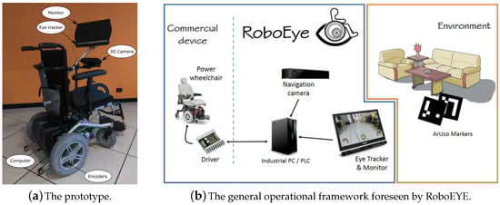
Figure 1.
RoboEYE.
3.1. Direct Drive
The direct drive modality can be selected by gazing at the corresponding button for 2 s on the designed interface. It should provide a versatile maneuverability, with reduced jerks, and a comfortable overall experience [29]. The proposed solution tackles such assumption by foreseeing the continuous variation of frontal and angular velocities with two different control laws: a rational one for the forward direction and a linear one for the rotations. In particular, the speed values increase moving the gaze from the central bottom part of the screen to the external corners, where it reaches the maximum allowable speed values. For both, a rest zone is defined, in the central bottom part of the monitor, where the wheelchair does not move.
The width of the area is defined to be comparable to the maximum eye tracker uncertainty, 100 pixel in our setup [20].
3.2. Semi-Autonomous Drive
Although direct control is a very natural and effective way of controlling motion, it may cause fatigue if used for long periods due to the need to keep attention on the monitor. The drive modality used for the semi-autonomous navigation, from [35], solves the problem of fatigue by enabling the wheelchair to reach the selected target position autonomously. It foresees the use of visual markers and Augmented Reality (AR) to localize a specific Point of Interest (POI) in the domestic environment and then drive the wheelchair there. The POI detection is performed by searching in the RGB frame through the ArUco library, something similar to [36,37] who analyze and use the segmentation algorithms in video-surveillance systems and cluttered environments.
The semi-autonomous navigation technique can be described as follows:
- Detection of POIs in the Field of View (FoV) of the camera through ArUco markers (each POI is uniquely defined by a couple of markers).
- Localization of the wheelchair with respect to each single POI.
- Planning of the best path to reach each POI.
- Show to the user the result about the path related to the reachable POIs and wait the choice.
- Execution of the selected path.
A localization algorithm [35] returns the position and the attitude of all POIs detected in the frontal FoV and, the AR engine shows pins in correspondence of these plus a maneuver calculated by a path planning algorithm [38]. The user can select a POI by gazing at its pin for 2 s while a loading circle marks the selection in time. After that, the wheelchair performs the maneuver by exploiting the path-following task from [38]. At the end of the path, the wheelchair automatically stops allowing the user to select a new POI or switch back to direct ocular driving.
However, in the context of domestic navigation, a fully dynamic path generation and action could be dangerous from the presence of narrow passages or obstacles. For this reason, the planning tool foresaw the division of the maneuver into two sub-parts: (i) a path that brings the wheelchair nearby the POI, and (ii) a fixed conclusive maneuver, defined for each POI, thus ensuring a safe approach or passage toward the target position.
The first is determined dynamically by exploiting a clothoid [38,39], a curve characterized by a continuous third-order curvature that ensures continuity in the jerk and so an optimal comfort level in the navigation. On top of that, the curve can be expressed analytically [40,41], providing as advantages a simple data management for control, HMI and AR, but also it facilitates the identification of obstacles and thus their avoidance. In this way, it is possible to evaluate the feasibility of the planned path. As for the final maneuver, this was associated with a graph-based map of the environment containing all POIs’ information. Depending on the type of POI, passage (i.e., through a door) or approach point (i.e., for reaching a desk), a linear or curvilinear segment was defined considering the geometry of the enthronement, the position of the markers and POI.
Given a selected POI and the complete path, the HMI checks and notifies the presence of obstacles along it. If so, the HMI highlights the path in red, preventing the execution of the maneuver. In this case, it is asked to the user himself to perform a corrective movement and bring the wheelchair into a suitable condition for a safe maneuver. This strategy stems from the desire to emphasize the user’s decision rather than the development of a fully autonomous system.
3.3. Prototype Components
The default electronics of a GR558 power wheelchair were removed and replaced with a commercial driver to power the original motors and two encoders on the wheels for odometric localization, Figure 1.
A Time of Flight (ToF) Microsoft Kinect V2 camera was mounted on the front of the wheelchair, a few centimeters above the user’s legs. The position was identified by considering the advice from a pool of volunteer testers, regular users of standard and special powered wheelchairs. They highlighted the importance of seeing their knees inside the driving interface, resulting in an effective strategy for better depth perception from the video interface [35].
A monitor was mounted at the front to show the user the HMI and the information from the TOF about the environment. A Windows PC manages the system logic. It collects the data from the encoders, calculates the position of the wheelchair and the control parameters required to pilot the drivers. It also manages the eye tracker (fastened below the monitor), the HMI and the ToF.
The PC was configured with a real-time Windows Operating System (OS). Both the HMI and the hardware manager were developed in UNITY, and the communication between the OS and the driver was structured over RS232 serial communication.
3.4. Navigation
Advanced robotics functionalities, based on video and 3D data processing, represent a core element of the semi-autonomous navigation modality. These were derived from specific libraries, which could not be directly coded at the HMI level, and were therefore coded in a dedicated C++ DLL. It was organized in three levels with two parallel tasks performing absolute localization and driver communication. On top of this, a wrapper class connects the C++ level to the C# of the HMI. Figure 2 shows a general scheme.
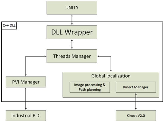
Figure 2.
A schematic representation of the DLL structure implemented on the prototype.
Wheelchair localization is performed by merging two contributions: encoder odometry and the custom-designed absolute localization method based on TOF data.
As for the first, this was derived from the odometric recursion from [42]. As for the second, this was designed differently from the canonical ones, which usually rely on matching range data with a previously created map [43]. A vision-based solution foresees the use of AR functionalities [44,45] to locate the wheelchair with respect to the POIs without the use of a map. The main advantages are: (i) the simplification of the data structure, (ii) a lower computational cost and (iii) the possible use of low-cost sensors, this at the only cost of introducing visual tags, as spatial anchors, into the domestic environment.
RoboEYE was designed to work mainly in a domestic environment. In this context, the furniture is a reliable landmark, as it is unlikely to be moved frequently over time. The most interesting furniture from an operational point of view, such as doors, tables and so on, were then referenced using AR tags [46]. For each of them, a POI was defined as a target pose . An operational example is a television: the POI is defined with respect to the marker, placed nearby the device so that the user can reach with the semi-autonomous navigation modality a predefined position, and watch it most comfortably.
The steps involved in the localization process are shown in the Algorithm 1 and detailed here:
- Data acquisition: the information concerning the color image and the depth stream data are collected by the ToF camera and passed to the processing block.
- Kinect position assessment: the system determines the transformation, in terms of height and attitude, between the sensor and the ground using a RANdom SAmple Consensus plane fitting (RANSAC) [47]. This task is fundamental to compensate for the mobility of the camera on the chassis, especially in the attitude.
- Roto-translation of 3D points: depth frames (3D cloud points) are transformed from the ToF to the wheelchair reference system. This also allows the organization of a more versatile ad efficient AR framework.
- Target detection: an ArUco function analyzes the RGB frames searching for markers. If present, the algorithm evaluates their 3D positions by isolating the corresponding 3D points at the markers. This strategy, compared to the one based on standard vision, works without the knowledge of the camera’s intrinsic parameters. The main advantage is to avoid a calibration phase, otherwise necessary. The localized markers, and the corresponding POIs, are then passed to the interface as possible target and anchor positions for autonomous navigation.
| Algorithm 1 Localization algorithm |
|
The two concurrent localization modalities are merged to minimize both the influence of the slow ToF camera localization and the drift error of the odometric localization. A Bayesian-based approach was considered by [48] for that, resulting in very accurate navigation, when compared to the single localization options, and thus a safer system.
4. Sources of Uncertainty
The passage through a door, or narrow passage in general, is one of the most important tasks for the sake of autonomous domestic mobility. In the case of a semi-autonomous motion, the maneuver depends on the localization of the wheelchair with respect to the environment, which is a task mostly required to a single, properly organized device. In RoboEYE, the ToF fulfills such a role in combination with the POIs. Both ToF and POIs detection are subject to uncertainty.
4.1. Uncertainty of Human–Machine Interface
The front monitor displays the HMI, shown in Figure 3, and presents the navigation options to the user. They include a video stream from the camera in the background, buttons to start/stop navigation in the foreground, and, on top of all the detected POIs with identified the feasible paths.
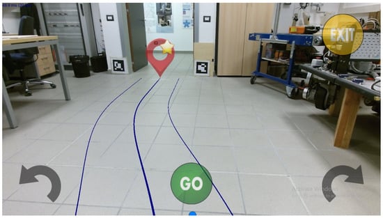
Figure 3.
The human–machine interface shown on the front monitor with Augmented Reality (AR) cues activated through ArUco Markers.
The graphics engine considers the role of uncertainty from eye-tracking and its effect on human–machine interaction, proportionally adapting the size of buttons and pins according to the magnitude of such parameter. It was computed online, exploiting an exponential moving average of the gazed point on the monitor over time:
is the value of the exponential moving average at a step k, is the difference of the gaze position in two consecutive steps and N is the number of samples considered in the moving average, set in the proposed application set to 10. A uniform weighting of was considered for all the samples in the average.
The presented organization achieved the main advantage of fast, reliable and structured access from high-level software interfaces to low-level variables, modules and functions, allowing the natural integration of kinematic information into the AR. The result was a natural, simple and efficient HMI resulting in a smooth and comfortable control of the motion of the wheelchair.
4.2. Uncertainty of ToF
The onboard position of the ToF device can be assessed with a limited accuracy since it has to be fixed at a critical point. From the specifications identified by the testers, to be effective in driving the ToF has to (i) be frontal to the system, (ii) point toward the floor to identify possible obstacles and (iii) allow easy repositioning to allow the user to sit in and get out of the wheelchair even with assistive equipment.
Such a setup implies possible small variations in the position of the device from the calibrated reference, caused by vibrations, slack in the mounting system, or mechanic tolerances. This can be modeled as uncertainty in such parameters, resulting in an error that propagates from the initial path planning, when the wheelchair is stationary, throughout the maneuver, where the path is automatically updated every time the target POI falls within the FoV of the ToF. The result is a non-negligible displacement of the wheelchair from the intended target position, which represents a dangerous condition for the user. For this reason, an error budget analysis was structured to highlight the influence of the uncertainty in the ToF position for the performance of the autonomous navigation toward a target POI.
4.3. Uncertainty of Marker-Based Localization
Any localization process exploited in (semi-)autonomous navigation should include, for safety reasons, an assessment of the uncertainty of the detected positions. In RoboEYE, this requirement was achieved through a repeatability analysis involving the measurement of static positions of multiple markers placed in the FoV of the ToF. The tests considered two conditions: distance and orientation. In the first, the marker and the wheelchair were aligned, moving the latter to different distances, Figure 4 reports the measurements as point-type markers. In the second, represented by the cross-type markers, the attitude of the wheelchair was changed with respect to the marker, keeping the position fixed.
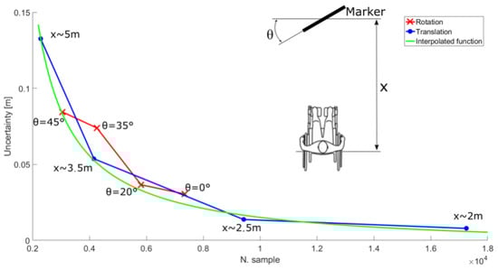
Figure 4.
The correlation between the standard deviation in marker localization versus the number of points associated with a marker.
The experimental evidence highlighted a correlation between the number of 3D points within the marker area and the covariance of the measure. Such observation was then exploited to determine the standard deviation of the position of the marker as a function of the number of points detected:
is the number of 3D points detected within the marker, and , , are numerical coefficients resulting from fitting Equation (2) with the experimental data. Equation (2) was applied on the main decomposition of the 3D point cloud at the marker, thus determining two contributes, frontal and transverse, and subsequently combining them in a covariance matrix.
5. Maneuver Modeling with Monte Carlo Simulation
A Monte Carlo simulation [49] was structured to model the influence of the uncertainty in the position of the ToF along with the maneuver. Figure 5 shows the spatial configuration considered, which represents an ideal operational scenario: an area starting 2 away from the wheelchair, 2 long and 4 wide. Within this area, a uniform grid of doors was defined with fixed steps of m in the directions x and y. For each , 5 attitudes ranging from 0 to 45 were defined. The simulation considered the wheelchair starting from the origin and the door defined at a position . The target pose was defined as a point placed m in front of the door.
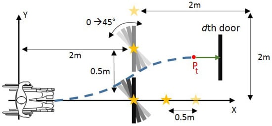
Figure 5.
The scheme of the tests used in the Monte Carlo simulation.
Only the upper part of the area (positive ys) was considered for symmetry. As a further simplification, only positive angles were considered for the attitude of s: negative angles simulate an approach from a high incidence direction, an unlikely operational condition given the vision-based structure of the navigation.
The simulation included the kinematic model of the wheelchair and the uncertainty in the kinematic parameters. The result is a set of covariance matrices along the executed path, which represent the possible true position reached by the wheelchair at a defined confidence level [42]. This was set to 99.7% (s) to maximize the reliability of the results, and hence the safety of the system.
Given the nth of the N simulation runs and the dth door, the nominal onboard position of the ToF is modified by adding a systematic error randomly selected from a pool of possible uncertainty levels in displacement, named , and attitude, . Such bias remains fixed for the entire duration of the nth run, and it causes an error in the generation of the virtual measurements linking the wheelchair to . To reduce the number of factors in the proposed analysis, the values defined by represent radial displacements and not independent x and y components. These were instead computed starting from the distance definition and by randomly selecting a displacement angle (different from ).
The simulation starts with the initial planning and motion of the wheelchair from the origin towards . After a defined latency, the simulation performs a data update as a new measurement of seen from the actual position of the wheelchair. A new path planning and path following operations are then run, structuring a loop that ends when the wheelchair is less than away from . After that, a conclusive planning step is performed and the final pose and the covariance matrix are recorded. As a final step, another 100 random seeds are taken from and used to project the position of the wheelchair towards the door’s line (a segment of length). Figure 6 shows an example of the simulation.
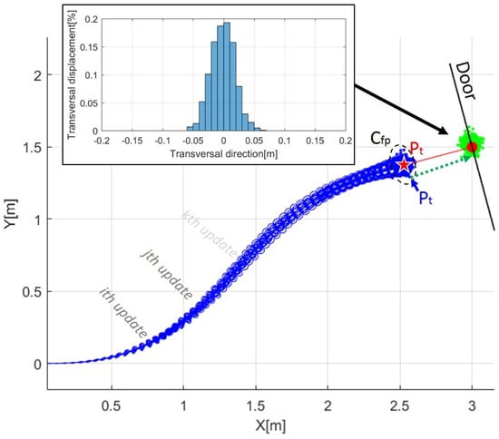
Figure 6.
Simulation example of the wheelchair path from the origin to the target pose : in black the reference geometry for the door, in red is the liner approach to the door, in blue are both the ellipses representing the uncertainty propagation along the path for all the simulated paths, the dots are the seeds from the final curvilinear positions and covariances and in green are the final positions after the conclusive linear path. The figure also shows histograms of the performance factor as the final transverse displacement of the wheelchair along the door line.
The kinematic parameters considered for the wheelchair model were a wheelbase of m and a wheel radius of m (). Regarding the data acquisition process, an update in the planning at 10 Hz was considered, equivalent to a routine every 3 samples from the ToF (native operational frequency of 30 Hz). The wheelchair speed was set to m/s, the fastest speed suitable for safe domestic use. Any lower speed reduces the influence of the uncertainty in the final position as it implies a slower motion and therefore more updates and the application of more corrective actions during the approach to the target position.
The levels of uncertainty considered in the sensor position were chosen based on hardware configurations, mounting and fastening options available with standard (certified) mechanical mounts:
- m
- [rad]
For each - configuration, 100 trials were run.
5.1. Minimum Door Clearance
The transverse displacement of the wheelchair along the door line was considered as a performance factor for each seed. From the distribution , the minimum door clearance was assessed using the following expression:
is the wheelchair width, while and represent the systematic and random errors in reaching the door: the first is computed as the mean of the distribution of s, the latter as the standard deviation. The value of stands as an additional safety factor (). Figure 7 shows a geometric representation of the formula.
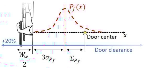
Figure 7.
Scheme for the assessment of the minimum door clearance involving the wheelchair width and the systematic and random errors in reaching the door of the distribution of performance factors s, respectively and .
Given the multidimensional structure of the data, the 2 s, and the 3 spatial coordinates of the door, the maximum value among the 5 available was used as a representation of the identified clearance. This condition is the most precautionary as the widest door clearance derives from it.
Figure 8 shows the resulting door clearance organized along the tested doors’ position at different levels of and . Figure 9a instead reports the maximum clearance value among the whole tested area.
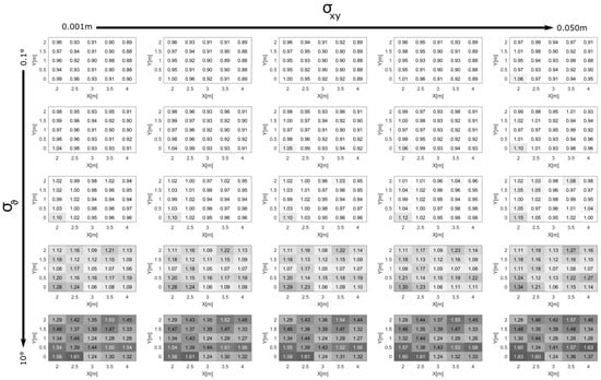
Figure 8.
Distributions of door clearance.
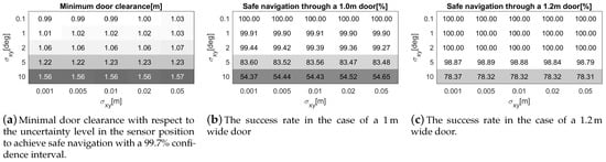
Figure 9.
Success rate in door passing, clearance versus s.
5.2. Success Rate
The success rate in navigating through a door for a given clearance was assessed by computing the percentage of seeds that resulted in a passage without impact, modeled as . Figure 9 shows the percentages for a door of 1 (a) and (b), standard dimensions for domestic environments in which a disabled subject lives [50].
Such results can be used in several ways: (i) to determine the minimum door clearance given an uncertainty level in the position of the sensor, (ii) to identify the maximum allowable s given the doors within a home or (iii) to identify the best trade-off condition for the design of the wheelchair and the environment in which it will be used.
In this work, the focus was on the latter point, identifying in the m clearance the suitable condition given an assessment of the position of the ToF with and lower than m and 2 deg, respectively. Between the two, the angular condition is the most restrictive one, and the RoboEYE design was modified accordingly by considering a vertical rather than horizontal rotating support.
The highlighted results are specific to the considered geometry and the implementation of the presented system. However, the definitions and methodology presented are general and aim to include in the design and modeling of the system all the relevant amount of interest for a better understanding of the autonomous system, its implications also to the operational environment. The method can be directly applied to different geometries and configurations of a wheelchair, or other similar applications, with only minor modifications in the parameter definition.
6. Experimental Testing
An experimental test campaign was also carried out. Similar to the previous analysis, the performance of semi-autonomous navigation was assessed through a repeatability analysis on the final positions reached by the real wheelchair given a set of initial, controlled states.
Two markers were set at a clearance of , Figure 10a shows the considered scheme and the semi-autonomous navigation activated by pointing as the associated POI. Figure 10 shows the sequence of action followed in the tests. The initial position [X′, Y′, θ] of the wheelchair was referenced to the reference frame , set at the center and aligned along with the door. The following test conditions were achieved:
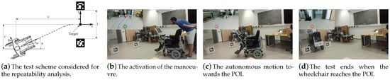
Figure 10.
An example of a semi-autonomous navigation action sequence, the same adopted for the repeatability analysis.
- fixed initial position and attitude;
- shifted from the initial reference position along the Y′ direction, from m to m in steps of m;
- all the tree initial conditions are changed randomly.
Table 1 shows the initial condition of the tests.

Table 1.
Initial conditions of the repeatability analysis.
The outcomes of the test, reported in Figure 11, were:
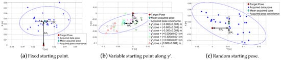
Figure 11.
Results of the repeatability analysis.
- a correlation between the initial shift along the y′ direction and the final position reached by the wheelchair, visible in Figure 11b with samples grouped accordingly to their initial starting position;
- in the case of a variable starting positions, maximum displacements from the target position of 0.18 m along the transversal direction, and 0.08 m longitudinally, Figure 11c;
- a systematic displacement between the mean position of the sample set and the target, probably deriving from the limited knowledge of extrinsic parameters of the ToF with respect to the wheelchair.
Table 2 reports the average offset between the target pose and the mean final wheelchair position, values that confirm the results achieved in simulation.
Table 2.
Results of repeatability analysis.
7. Conclusions
A domestic robotic wheelchair driven by the user’s gaze was designed in this work to allow users with severe motor disability to move easily and autonomously within their homes. The wheelchair, named RoboEYE, was developed considering commercial contactless technology to interface the user with its control. This non-invasive technology and other components are added to a reconfigured power wheelchair of Nuova Blandino Srl. Compared to other state-of-the-art solutions, RoboEYE offers (i) the minimum invasiveness to the user, (ii) it integrates functionalities derived from the mobile robotics field, (iii) it considers the role of the uncertainty in the human–machine interaction and (iv) it is based on low-cost hardware solutions. The result is an efficient and cost-effective system, suitable for the technological transfer to its potential users.
Two options are offered to the user: (a) direct eye control, in which the motion of the wheelchair is directly connected to the gazed point on the monitor, and (b) semi-autonomous, in which the user only has to select a visual target to allow autonomous maneuvering towards such point. The main investigation of this work regards the latter, potentially the most hazardous of the two. This driving modality allows the user to navigate safely also through narrow passages without fatigue. In particular, the performance of the system was evaluated in detail by performing both numerical simulations and experimental verification. The analysis showed a maximum transverse displacement from the target position of m, resulting from uncertainties that inevitably affect the knowledge of the parameters of the kinematics and the sensor position. For the considered wheelchair, of m width, the operational outcome is a minimum clearance of m for autonomous, reliable and safe navigation through a narrow passage. Such a requirement meets the standards for a domestic usage of the system, such as a house with doors wider than 1 m, which is a common dimension for a structured environment for a wheelchair user. Another evidence obtained from the results is that the angular condition of the ToF has more impact during the motion than , so more attention should be given to this parameter in wheelchair design.
The advantage of the methodology presented here is that with minor changes it can be applied to different geometries and configurations of a wheelchair, or other similar applications.
The limitations of the proposed approach are related to the fact that RoboEYE is designed to work mainly in a domestic environment or more generally in indoor environments. The technologies used for eye-tracking would be affected by sunlight if the system were used outdoors. Another issue not discussed here is related to the level of illumination that can negatively affect the performances of the POIs detection.
Author Contributions
Conceptualization, L.M.; Resources, G.M.A.G.; Software, L.M., M.Z., P.T. and M.T.; Supervision, L.M. and M.D.C.; Validation, L.M.; Writing—original draft, L.M., A.L. and M.P. All authors have read and agreed to the published version of the manuscript.
Funding
This research received no external funding.
Institutional Review Board Statement
The study was conducted according to the guidelines of the Declaration of Helsinki, and approved by the Ethics Committee of the University of Trento (protocol code 2016-020 and date of approval 21 July 2021).
Informed Consent Statement
Informed consent was obtained from all subjects involved in the study.
Acknowledgments
This research was supported by the company Nuova Blandino Srl, Alberto Tassone, and Andrea Gravina, who provided the necessary devices and technology. We would also like to thank the Abilita service of APSS and the people involved in the project, who provided insight and expertise that helped the research. The research team would like to thank all the volunteers who participated in the testing campaign. Their willingness to help us was fundamental to the realization of the device and this work. Special thanks go to Corsi, for his inestimable help and strong will.
Conflicts of Interest
The authors declare no conflict of interest.
References
- Armanini, A.; Conci, N. Eye tracking as an accessible assistive tool. In Proceedings of the 2010 11th International Workshop on Image Analysis for Multimedia Interactive Services (WIAMIS), Desenzano del Garda, Italy, 12–14 April 2010; pp. 1–4. [Google Scholar]
- Al-Rahayfeh, A.; Faezipour, M. Eye tracking and head movement detection: A state-of-art survey. IEEE J. Transl. Eng. Health Med. 2013, 1, 2100212. [Google Scholar] [CrossRef] [PubMed]
- Cremers, G. Hybrid-powered wheelchair: A combination of arm force and electrical power for propelling a wheelchair. J. Med. Eng. Technol. 1989, 13, 142–148. [Google Scholar] [CrossRef] [PubMed]
- Wieczorek, B.; Warguła, Ł.; Rybarczyk, D. Impact of a hybrid assisted wheelchair propulsion system on motion kinematics during climbing up a slope. Appl. Sci. 2020, 10, 1025. [Google Scholar] [CrossRef]
- Li, J.; Ji, H.; Cao, L.; Zang, D.; Gu, R.; Xia, B.; Wu, Q. Evaluation and application of a hybrid brain computer interface for real wheelchair parallel control with multi-degree of freedom. Int. J. Neural Syst. 2014, 24, 1450014. [Google Scholar] [CrossRef] [PubMed]
- Wieczorek, B.; Kukla, M. Effects of the performance parameters of a wheelchair on the changes in the position of the centre of gravity of the human body in dynamic condition. PLoS ONE 2019, 14, e0226013. [Google Scholar] [CrossRef] [PubMed]
- Leishman, F.; Monfort, V.; Horn, O.; Bourhis, G. Driving assistance by deictic control for a smart wheelchair: The assessment issue. IEEE Trans. Hum.-Mach. Syst. 2014, 44, 66–77. [Google Scholar] [CrossRef]
- Leaman, J.; La, H.M. A comprehensive review of smart wheelchairs: Past, present, and future. IEEE Trans. Hum.-Mach. Syst. 2017, 47, 486–499. [Google Scholar] [CrossRef]
- Elliott, M.A.; Malvar, H.; Maassel, L.L.; Campbell, J.; Kulkarni, H.; Spiridonova, I.; Sophy, N.; Beavers, J.; Paradiso, A.; Needham, C.; et al. Eye-controlled, power wheelchair performs well for ALS patients. Muscle Nerve 2019, 60, 513–519. [Google Scholar] [CrossRef] [PubMed]
- Cruz, R.; Souza, V.; Filho, T.B.; Lucena, V. Electric Powered Wheelchair Command by Information Fusion from Eye Tracking and BCI. In Proceedings of the 2019 IEEE International Conference on Consumer Electronics (ICCE), Las Vegas, NV, USA, 11–13 January 2019; pp. 1–2. [Google Scholar] [CrossRef]
- Shinde, S.; Kumar, S.; Johri, P. A Review: Eye Tracking Interface with Embedded System IOT. In Proceedings of the 2018 International Conference on Computing, Power and Communication Technologies (GUCON), Greater Noida, India, 28–29 September 2018; pp. 791–795. [Google Scholar] [CrossRef]
- Meena, Y.K.; Cecotti, H.; Wong-Lin, K.; Prasad, G. A multimodal interface to resolve the Midas-Touch problem in gaze controlled wheelchair. In Proceedings of the 2017 39th Annual International Conference of the IEEE Engineering in Medicine and Biology Society (EMBC), Jeju Island, Korea, 11–15 July 2017; pp. 905–908. [Google Scholar] [CrossRef]
- Bergstrom, J.R.; Schall, A. Eye Tracking in User Experience Design; Elsevier: Amsterdam, The Netherlands, 2014. [Google Scholar]
- Duchowski, A.T. Eye tracking methodology. In Theory and Practice; Springer: Zürich, Switzerland, 2007; Volume 328. [Google Scholar]
- Voronka, N.; Jacobus, C.J. Low-Cost Non-Imaging Eye Tracker System for Computer Control. U.S. Patent 6,299,308, 9 October 2001. [Google Scholar]
- Guestrin, E.D.; Eizenman, M. General theory of remote gaze estimation using the pupil center and corneal reflections. IEEE Trans. Biomed. Eng. 2006, 53, 1124–1133. [Google Scholar] [CrossRef] [PubMed]
- Brolly, X.L.; Mulligan, J.B. Implicit calibration of a remote gaze tracker. In Proceedings of the CVPRW’04, Conference on Computer Vision and Pattern Recognition Workshop, Washington, DC, USA, 27 June–2 July 2004; p. 134. [Google Scholar]
- Holmqvist, K.; Nyström, M.; Mulvey, F. Eye tracker data quality: What it is and how to measure it. In Proceedings of the Symposium on Eye Tracking Research and Applications, Santa Barbara, CA, USA, 28–30 March 2012; pp. 45–52. [Google Scholar]
- Cerrolaza, J.J.; Villanueva, A.; Villanueva, M.; Cabeza, R. Error characterization and compensation in eye tracking systems. In Proceedings of the Symposium on Eye Tracking Research and Applications, Santa Barbara, CA, USA, 28–30 March 2012; pp. 205–208. [Google Scholar]
- Fornaser, A.; De Cecco, M.; Leuci, M.; Conci, N.; Daldoss, M.; Armanini, A.; Maule, L.; De Natale, F.; Da Lio, M. Eye tracker uncertainty analysis and modelling in real time. J. Phys. Conf. Ser. 2017, 778, 012002. [Google Scholar] [CrossRef]
- De Cecco, M.; Zanetti, M.; Fornaser, A.; Leuci, M.; Conci, N. Inter-eye: Interactive error compensation for eye-tracking devices. In AIP Conference Proceedings; AIP Publishing: Ancona, Italy, 2016; Volume 1740, p. 050007. [Google Scholar]
- Zanetti, M.; De Cecco, M.; Fornaser, A.; Leuci, M.; Conci, N. The use of INTER-EYE for 3D eye-tracking systematic error compensation. In Proceedings of the ELMAR, 2016 International Symposium, Zadar, Croatia, 12–14 September 2016; pp. 173–176. [Google Scholar]
- Lin, C.S.; Ho, C.W.; Chen, W.C.; Chiu, C.C.; Yeh, M.S. Powered wheelchair controlled by eye-tracking system. Opt. Appl. 2006, XXXVI, 36. [Google Scholar]
- Pingali, T.R.; Dubey, S.; Shivaprasad, A.; Varshney, A.; Ravishankar, S.; Pingali, G.R.; Polisetty, N.K.; Manjunath, N.; Padmaja, K. Eye-gesture controlled intelligent wheelchair using Electro-Oculography. In Proceedings of the 2014 IEEE International Symposium on Circuits and Systems (ISCAS), Melbourne, Australia, 1–5 June 2014; pp. 2065–2068. [Google Scholar]
- Bi, L.; Fan, X.A.; Liu, Y. EEG-based brain-controlled mobile robots: A survey. IEEE Trans. Hum.-Mach. Syst. 2013, 43, 161–176. [Google Scholar] [CrossRef]
- Purwanto, D.; Mardiyanto, R.; Arai, K. Electric wheelchair control with gaze direction and eye blinking. Artif. Life Robot. 2009, 14, 397. [Google Scholar] [CrossRef]
- Wästlund, E.; Sponseller, K.; Pettersson, O.; Bared, A. Evaluating gaze-driven power wheelchair with navigation support for persons with disabilities. J. Rehabil. Res. Dev. 2015, 52, 815–826. [Google Scholar] [CrossRef] [PubMed]
- Tall, M.; Alapetite, A.; San Agustin, J.; Skovsgaard, H.H.; Hansen, J.P.; Hansen, D.W.; Møllenbach, E. Gaze-controlled driving. In Proceedings of the CHI’09 Extended Abstracts on Human Factors in Computing Systems, Boston, MA, USA, 4–9 April 2009; pp. 4387–4392. [Google Scholar]
- Maule, L.; Fornaser, A.; Leuci, M.; Conci, N.; Da Lio, M.; De Cecco, M. Development of innovative HMI strategies for eye controlled wheelchairs in virtual reality. In Proceedings of the International Conference on Augmented Reality, Virtual Reality and Computer Graphics, Lecce, Italy, 15–18 June 2016; pp. 358–377. [Google Scholar]
- Araujo, J.M.; Zhang, G.; Hansen, J.P.P.; Puthusserypady, S. Exploring Eye-Gaze Wheelchair Control. In Proceedings of the ACM Symposium on Eye Tracking Research and Applications, Stuttgart, Germany, 2–5 June 2020; pp. 1–8. [Google Scholar]
- Singer, C.C.; Hartmann, B. See-Thru: Towards Minimally Obstructive Eye-Controlled Wheelchair Interfaces. In Proceedings of the 21st International ACM SIGACCESS Conference on Computers and Accessibility, Pittsburgh, PA, USA, 28–30 October 2019; pp. 459–469. [Google Scholar]
- Subramanian, M.; Songur, N.; Adjei, D.; Orlov, P.; Faisal, A.A. A.Eye Drive: Gaze-based semi-autonomous wheelchair interface. In Proceedings of the 2019 41st Annual International Conference of the IEEE Engineering in Medicine and Biology Society (EMBC), Berlin, Germany, 23–27 July 2019; pp. 5967–5970. [Google Scholar]
- Jafar, F.; Fatima, S.F.; Mushtaq, H.R.; Khan, S.; Rasheed, A.; Sadaf, M. Eye Controlled Wheelchair Using Transfer Learning. In Proceedings of the 2019 International Symposium on Recent Advances in Electrical Engineering (RAEE), Islamabad, Pakistan, 28–29 August 2019; Volume 4, pp. 1–5. [Google Scholar]
- Cojocaru, D.; Manta, L.F.; Vladu, I.C.; Dragomir, A.; Mariniuc, A.M. Using an Eye Gaze New Combined Approach to Control a Wheelchair Movement. In Proceedings of the 2019 23rd International Conference on System Theory, Control and Computing (ICSTCC), Sinaia, Romania, 9–11 October 2019; pp. 626–631. [Google Scholar]
- Maule, L.; Fornaser, A.; Tomasin, P.; Tavernini, M.; Minotto, G.; Da Lio, M.; De Cecco, M. Augmented Robotics for Electronic Wheelchair to Enhance Mobility in Domestic Environment. In Proceedings of the International Conference on Augmented Reality, Virtual Reality and Computer Graphics, Ugento, Italy, 12–15 June 2017; pp. 22–32. [Google Scholar]
- Peleshko, D.; Ivanov, Y.; Sharov, B.; Izonin, I.; Borzov, Y. Design and implementation of visitors queue density analysis and registration method for retail videosurveillance purposes. In Proceedings of the 2016 IEEE First International Conference on Data Stream Mining & Processing (DSMP), Lviv, Ukraine, 23–27 August 2016; pp. 159–162. [Google Scholar]
- Ivanov, Y.; Peleshko, D.; Makoveychuk, O.; Izonin, I.; Malets, I.; Lotoshunska, N.; Batyuk, D. Adaptive moving object segmentation algorithms in cluttered environments. In Proceedings of the Experience of Designing and Application of CAD Systems in Microelectronics, Lviv, Ukraine, 24–27 February 2015; pp. 97–99. [Google Scholar]
- De Cecco, M.; Bertolazzi, E.; Miori, G.; Oboe, R.; Baglivo, L. PC-Sliding for vehicles path planning and control. In Proceedings of the ICINCO 2007, 4th International Congress on Informatics in Automation, Control and Robotics, Angers, France, 9–12 May 2007. [Google Scholar]
- Bertolazzi, E.; Frego, M. Fast and accurate clothoid fitting. arXiv 2012, arXiv:1209.0910. [Google Scholar]
- Frego, M.; Bertolazzi, E.; Biral, F.; Fontanelli, D.; Palopoli, L. Semi-analytical minimum time solutions with velocity constraints for trajectory following of vehicles. Automatica 2017, 86, 18–28. [Google Scholar] [CrossRef]
- Bertolazzi, E.; Frego, M. Interpolating clothoid splines with curvature continuity. Math. Methods Appl. Sci. 2018, 41, 1723–1737. [Google Scholar] [CrossRef]
- De Cecco, M.; Baglivo, L.; Pertile, M. Real-time uncertainty estimation of odometric trajectory as a function of the actual manoeuvres of autonomous guided vehicles. In Proceedings of the 2006 IEEE International Workshop on Advanced Methods for Uncertainty Estimation in Measurement, AMUEM 2006, Sardinia, Italy, 20–21 April 2006; pp. 80–85. [Google Scholar]
- Li, Z.; Xiong, Y.; Zhou, L. ROS-Based Indoor Autonomous Exploration and Navigation Wheelchair. In Proceedings of the 2017 10th International Symposium on Computational Intelligence and Design (ISCID), Hangzhou, China, 9–10 December 2017; Volume 2, pp. 132–135. [Google Scholar]
- Kato, H.; Billinghurst, M. Marker tracking and hmd calibration for a video-based augmented reality conferencing system. In Proceedings of the 2nd IEEE and ACM International Workshop on Augmented Reality (IWAR’99), San Francisco, CA, USA, 20–21 October 1999; pp. 85–94. [Google Scholar]
- Garrido-Jurado, S.; Muñoz-Salinas, R.; Madrid-Cuevas, F.J.; Marín-Jiménez, M.J. Automatic generation and detection of highly reliable fiducial markers under occlusion. Pattern Recognit. 2014, 47, 2280–2292. [Google Scholar] [CrossRef]
- Romero-Ramirez, F.J.; Muñoz-Salinas, R.; Medina-Carnicer, R. Speeded up Detection of Squared Fiducial Markers. Image Vis. Comput. 2018, 76, 38–47. [Google Scholar] [CrossRef]
- Fischler, M.A.; Bolles, R.C. Random sample consensus: A paradigm for model fitting with applications to image analysis and automated cartography. Commun. ACM 1981, 24, 381–395. [Google Scholar] [CrossRef]
- De Cecco, M.; Baglivo, L.; Ervas, E.; Marcuzzi, E. Asynchronous and time-delayed sensor fusion of a laser scanner navigation system and odometry. In Proceedings of the XVIII IMEKO World Congress, Metrology for a Sustainable Development, Rio de Janeiro, Brazil, 17–22 September 2006; pp. 17–22. [Google Scholar]
- JCGM. Evaluation of Measurement Data—Supplement 1 to the “Guide to the Expression of Uncertainty in Measurement”-Propagation of Distributions Using a Monte Carlo Method; Elsevier: Amsterdam, The Netherlands, 2008. [Google Scholar]
- Irish Wheelchair Association. Best Practice Access Guidelines, Designing Accessible Environments; Irish Wheelchair Association: Dublin, Ireland, 2014. [Google Scholar]
Publisher’s Note: MDPI stays neutral with regard to jurisdictional claims in published maps and institutional affiliations. |
© 2021 by the authors. Licensee MDPI, Basel, Switzerland. This article is an open access article distributed under the terms and conditions of the Creative Commons Attribution (CC BY) license (http://creativecommons.org/licenses/by/4.0/).