Abstract
This work proposes new interface conditions between the layers of a three-dimensional composite structure in the framework of coupled thermoelasticity. More precisely, the mechanical behavior of two linear isotropic thermoelastic solids, bonded together by a thin layer, constituted of a linear isotropic thermoelastic material, is studied by means of an asymptotic analysis. After defining a small parameter , which tends to zero, associated with the thickness and constitutive coefficients of the intermediate layer, two different limit models and their associated limit problems, the so-called soft and hard thermoelastic interface models, are characterized. The asymptotic expansion method is reviewed by taking into account the effect of higher-order terms and defining a generalized thermoelastic interface law which comprises the above aforementioned models, as presented previously. A numerical example is presented to show the efficiency of the proposed methodology, based on a finite element approach developed previously.
1. Introduction
The use of composite structures, obtained by bonding together simpler structural members, has spread in all fields of engineering in the last decades. On the one hand, the structural assembly presents a significant improvement of the mechanical properties and an enhancement of its performances. On the other hand, the bonded joints among the composite constituents may cause a jump of the physical fields at the interface level and radically modify the global mechanical response. Thus, the correct modeling of composite interfaces is crucial in the understanding and design of complex structures.
From a theoretical point of view, the bonded region is considered as a thin interphase between two adjacent parts. By letting the thickness of this layer tend to zero, the interphase is reduced into a two-dimensional surface, called imperfect interface, where ad-hoc transmission conditions in terms of the representative physical fields are prescribed. The contact laws can be derived by means of classical variational tools and more refined mathematical techniques, in different physical frameworks, involving uncoupled (thermal conduction and elasticity) and coupled (piezoelectricity and multiphysics) phenomena.
Concerning the thermal (or electrical) conduction case, two main interface laws have been formulated: the lowly-conducting (LC) or Kapitza’s model and highly-conducting (HC) model. The LC model provides a discontinuity of the temperature field (electric potential) and a continuity of the normal heat flow (electric displacement) across the interface (see, e.g., [1,2,3]). The HC model gives rise to two-dimensional Young–Laplace equation, defined on the interface, depending on the jump of the normal heat flow (electric displacement) and maintaining the temperature (electric potential) continuous (see, e.g., [4,5]). A unifying approach of a general imperfect interface model, involving the concurrent jump of both the temperature field and the normal heat flow, recovering both the LC and HC models, was proposed by [6,7]. Concerning the linear elastic case, three types of imperfect interfaces have been proposed: the spring-layer interface model (SL) (soft interface), the coherent interface (CI) (rigid interface), and the general imperfect interface. The SL models considers that the traction vector is continuous across the interface, while the displacement presents a jump linearly proportional to the traction vector (see, e.g., [8,9]). The CI model has been developed for continuum theories with surface effects and nano-sized materials (see, e.g., [10,11,12]): the traction vector suffers a jump, while the displacement field is continuous across the interface. Finally, in the general imperfect model, both the displacement and normal traction fields are discontinuous across the interface [13,14].
The asymptotic expansions method and convergence approaches represent mathematical tools, usually employed in the derivation and justification of classical thin structures and layered plates [15,16,17,18,19]. These methodologies are based on the behavior of the problem solution, when a small parameter , related to the thickness of the interphase, tends to zero. Considering that the material properties of the intermediate layer depend on , different limit behaviors can be derived by means of the asymptotic analysis: for , an SL interface model can be recovered (see, e.g., [20,21]); and, for , the CI interface model is mathematically justified by means of strong convergence arguments in [22,23]. Within the framework of a higher-order theory, assuming the interphase elastic constants are independent of the small thickness (), the asymptotic analysis yields to a general stiff imperfect interface condition, prescribing both the jumps of the displacement and traction vector fields and recovering as a particular case the perfect contact conditions at the zeroth-order [24,25,26,27,28].The above transmission conditions have been generalized by considering some multiphysics and multifield couplings, such as in piezoelectricity and magneto-electro-thermo-elasticity [29,30], poroelasticity [31], and micropolar elasticity [32].
The goal of the present work is to identify the interface limit models of a composite constituted by a thin thermoelastic layer surrounded by two thermoelastic bodies in the framework of dynamic coupled thermoelasticity. Different situations are analyzed by varying the stiffnesses ratios between the middle layer and the adherents: namely, the soft thermoelastic lowly conducting interface, where the intermediate material coefficients have the order of magnitude with respect to those of the surrounding bodies, and the hard thermoelastic moderately conducting interface, where the constitutive parameters have the same order of magnitude. Following the ideas of [33], a generalized interface law is derived, comprising the aforementioned behaviors. A numerical investigation was performed in the framework of the finite element method (FEM), employing the approach developed in [34] for multiphysics problems, in order to assess the validity of the asymptotic models. Convergence results and a comparison between the full 3D model and the generalized interface problem are given.
2. Position of the Problem
In the sequel, Greek indices range in the set , Latin indices range in the set , and the Einstein’s summation convention with respect to the repeated indices is adopted. Let us consider a three-dimensional Euclidian space identified by and such that the three vectors form an orthonormal basis. Let be the space of square matrices. We introduce the following notations for the inner products: , for all vectors and in and , for all and in .
Let us define a small parameter . We consider the assembly constituted of two solids , called the adherents, bonded together by an intermediate thin layer of thickness , called the adhesive, with cross-section . In the following, and S are called interphase and interface, respectively. Let be the plane interfaces between the interphase and the adherents and let denote the composite system comprising the interphase and the adherents (cf. Figure 1a).
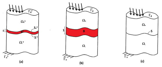
Figure 1.
Initial (a); rescaled (b); and limit (c) configurations of the composite.
Let us assume that and are constituted by three homogeneous linear isotropic thermoelastic materials, whose constitutive laws are defined as follows:
where is the Cauchy stress tensor, associated with the linearized strain tensor , represents the thermodynamic entropy and is the heat flow field. Constants , , , , and represent the Lamé’s constants, the thermal stress coefficient, the calorific capacity, and the thermal conductivity, respectively.
The thermoelastic state is defined by the couple , where and are the displacement field and variation of temperature, respectively. The thermoelastic composite is subject to body forces and heat source , applied on the top and bottom bodies, while all thermo-mechanical loadings and inertia forces are neglected in the intermediate layer . The thermoelastic state verifies the following coupled thermoelasticity system:
where denotes the time derivative of f and represents a reference temperature. The transmission conditions across the interfaces and implies the continuity of the state and of its normal dual counterpart with respect to , meaning that , , , on , where stands for the jump function evaluated at the interface . The boundary conditions are posed on , with ; we recall that . For simplicity, we assume homogeneous boundary conditions on , concerning displacements and temperature, and non-homogeneous boundary conditions on , concerning surface forces and surface heat flow . Hence, one has: and on , and and on , where is the outer unit normal vector to . The initial conditions are posed in . Let , , and be, respectively, the variation of temperature, the displacement, and velocity fields at time ; one has and in .
Let us introduce the functional spaces and . Given a certain state , for all test functions and for any fixed , we introduce the following bilinear and linear forms:
The variational form of the coupled thermoelastic system defined on the variable domain reads as follows:
for all , with initial condition , , and . The coupled hyperbolic–parabolic equations associated with variation problem (5) imply a degenerate system. Hence, the standard existence theorems are not applicable. For instance, in [35,36], by applying the pseudo-monotone theory, a weak solution is provided for a sufficiently small thermal stress coupling coefficient. In [37,38], a solution to the implicit evolution equation is derived after time-differentiation of the equilibrium equation provided by sufficiently smooth data of the problem. Under suitable regularity properties of the initial data, source and boundary values, and constitutive parameters, the well-posedness of thermo-electro-elastic evolution problem is extensively discussed in [39]: the proof of existence, uniqueness, and regularity of the solution has been obtained through the Faedo–Galerkin method. The existence and uniqueness theorems have also been extended to the thermo-electro-magneto-elastic case [40] and can be easily adapted to the present coupled thermoelastic problem.
Rescaling
To study the asymptotic behavior of the solution of problem (5) when tends to zero, we rewrite the problem on a fixed domain independent of . By using the approach of [15], we consider the bijection given by
where, after the change of variables, the adherents occupy and the interphase . The sets denote the interfaces between B and and is the rescaled configuration of the composite. Lastly, and indicate the images through of and (cf. Figure 1b). Consequently, and in and and in In the sequel, only if necessary, and denote the restrictions of functions to and B.
The constitutive coefficients of are assumed to be independent of , while the constitutive coefficients of present the following dependences on : , , , , and , with . Two different limit behaviors are characterized according to the choice of the exponent p: by choosing , a model for a soft thermoelastic interface with low conductivity is deduced; and, when , a model for a hard thermoelastic interface with moderate conductivity is obtained. Finally, the data, unknowns, and test functions verify the following scaling assumptions: , , , , , ,. Thus, .
According to the previous hypothesis, problem (5) can be reformulated on a fixed domain independent of . Thus, the following rescaled problem (in the sequel, we omit the explicit dependences on time t of the unknowns and data) is obtained:
for all , , with initial condition , , and , where
where
and
Now, an asymptotic analysis of the rescaled problem (7) can be performed. Since the rescaled problem (7) has a polynomial structure with respect to the small parameter , we can look for the solution of the problem as a series of powers of :
where and . By substituting (16) into the rescaled problem (7), and by identifying the terms with identical power of , as customary, a set of variational problems is obtained to be solved in order to characterize the limit thermoelastic state , the first-order corrector term and their associated limit problem, for . The order 1 can be considered as a corrector term of the order 0, giving a better approximation of the initial model.
3. The Soft Thermoelastic Interface Model
In this section, the limit model for a soft thermoelastic interface model, corresponding to an adhesive which is weaker with respect to the adherents, is derived. By choosing and injecting (16) into (7), the following set of variational problems is obtained:
In the sequel, the limit problems at order 0 and order 1 are presented, by skipping all the mathematical technicalities involved in the solution of problems (see [33] for a detailed description of the asymptotic analysis).
- Order 0 model
- Order 1 model
where and , denote, respectively, the mean value and the jump functions at the interfaces. The soft thermoelastic interface models at order 0 and order 1 present various similarities, compared with the linear elastic case [27]. At order 0, from a mechanical point of view, the interface behaves as linear springs reacting to the jump between the top and bottom displacements and temperature, while the traction vector and normal heat flow are remains continuous. The order 1 model provides a mixed contact law, expressed by a concurrent discontinuity in terms of thermoelastic state, traction vector, and normal heat flow. The order 1 transmission conditions can be also rewritten in terms of and , as follows:
The jump and mean values of the traction vector and normal heat flow at the interface depend on and are analogous to those obtained for the soft elastic case in [26]. It is interesting to notice that, at order 1, the jump of the heat flow at the interface inside the intermediate layer depend on the variation in time of the normal displacement .
4. The Hard Thermoelastic Interface Model
In this section, the limit model for a hard thermoelastic interface, corresponding to an intermediate layer having the same rigidities of the top and bottom bodies, is derived. Let , the asymptotic expansion (16) is inserted in (7), and the following set of variational problems is obtained:
A detailed equivalent analysis on the solution of the variational problems can be found in [33]. In the sequel, the limit problems at order 0 and order 1 are presented.
- Order 0 model
- Order 1 model
where , , with and , denotes the two-dimensional Laplacian operator. Note that, in this case, and .
The hard thermoelastic interface problems above present the same structures of the analogous linear elastic hard interface models [24,25,26]. Concerning the order 0, the transmission conditions provide a continuity of the thermoelastic state and of its conjugated counterpart, which is typical for adhesives having the same rigidity properties of the adherents. In this case, the upper and lower bodies are perfectly bonded together. At order 1, a mixed interface model is obtained, characterized by a jump of the state and traction vector depending on the values of the thermoelastic state and traction vector at order 0. These order 0 terms are known since they have been determined in the previous problem and they appear in the formulation as source terms. The interface conditions at order 1 can be interpreted as the two-dimensional coupled thermoelastic problem defined on the plane of the interface.
5. Generalized Interface Transmission Conditions
In [26,33], it has been shown that it is possible to obtain a condensed form of transmission conditions summarizing both the orders 0 and 1 of the soft and hard cases in only one couple of equations in terms of the jump of the displacement field and tractions at the interface. Equivalently, it is possible to define an implicit general thermoelastic interface law starting from the hard case, comprising the order 0 and order 1 soft and hard thermoelastic interface models.
To this end, by denoting by , and , suitable approximations of , and , respectively, and following the approach developed in [26,33], one can obtain the implicit form of the transmission conditions:
with .
To write the variational formulation of the general coupled thermoelastic interface problem, the expression of the general transmission conditions presented in (24) is employed. In what follows, for the sake of simplicity, the indices and symbol are omitted. Let us write the variational form of the equilibrium equations on each sub-domain and . The sum of the two equations leads to
which can be written
letting and . Then, using the property and relations (24), and after an integration by parts, one has
for all , where , with , , and
where , and denote the loads on the lateral boundary of the interface , with outer unit normal vector (see [33]).
6. FEM Implementation
The numerical simulations were carried out by means of the finite element method, discretizing the variational problem (27). This helped validate the proposed asymptotic approach. The FEM analysis was performed considering the coupled dynamic thermoelastic problem and comparing the solution of the three-phase model (two adherents and adhesive) with the generalized interface (two adherents + interface). The problem was solved employing the software GetFem++ (see [41,42] for more details), with a standard linear solver (conjugate gradient). For that purpose, standard piecewise linear finite elements were considered.
Let us consider a thermoelastic laminated plate occupying a 3D domain defined by , with 1 cm, , . (see Figure 2). Clearly, with self-explanatory notation, , , and . The adherents are made of Material 1, while the adhesive is constituted by Material 2.
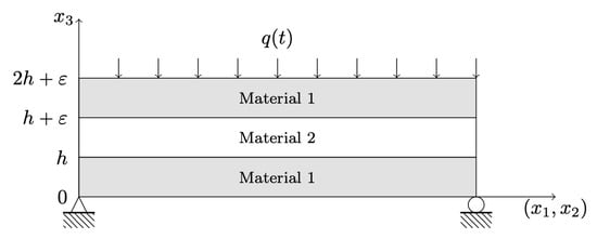
Figure 2.
The 3D geometry of the thermoelastic laminated plate represented in the plane
Simply supported boundary conditions are considered on the bottom edges of the composite plate. The plate is subject to a thermal shock on the top face, with and , whose plot is illustrated in Figure 3. The bottom face is thermally insulated . No volume or surface mechanical loads were applied .
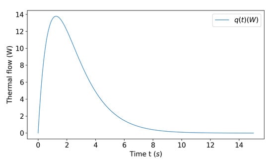
Figure 3.
Applied heat flow shock.
The FEM discretization was carried out using piecewise linear finite elements on hexahedrons, with 7280 nodes (29,203 degrees of freedom) for the three-phase problem and 5824 nodes (23,635 degrees of freedom) for the problem with the generalized interface law. The time discretization was realized using a Newmark-beta scheme with and for the second time derivative of the displacements, and a Crank–Nicholson scheme for the first derivative of the thermodynamic entropy. It is worth noting that both methods are unconditionally stable and of order two in time. The time step of discretization is equal to s.
The numerical example considers a composite plate, in which the adherents and the adhesive have very different thermo-mechanical properties. Material 1 is aluminum (Al), while Material 2 is a polyvinyl chloride (PVC) foam. The constitutive parameters are listed in Table 1.

Table 1.
Thermoelastic material properties for Al and PVC Foam.
To evaluate the accuracy of the asymptotic analysis, the influence of the relative thickness , for fixed time instants, on the -relative error was investigated. The -relative errors and was computed taking into account the solution of the initial three-phase problem, discretized with a FE mesh, and the solution of the interface problem (27). Table 2 and Table 3 report the relative error values for increasing time and vanishing relative thickness.

Table 2.
Relative error .

Table 3.
Relative error .
The convergence diagrams of the the relative -norms of the displacements and temperatures, obtained with the three-phase problem and the reduced interface problem, are plotted in Figure 4, as the thickness ratio tends to zero, at time s and s, respectively. Moreover, the evolution in time of the -relative is reported in Figure 5.
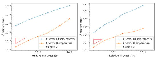
Figure 4.
Convergence diagrams with respect to for: s (left); and s (right).
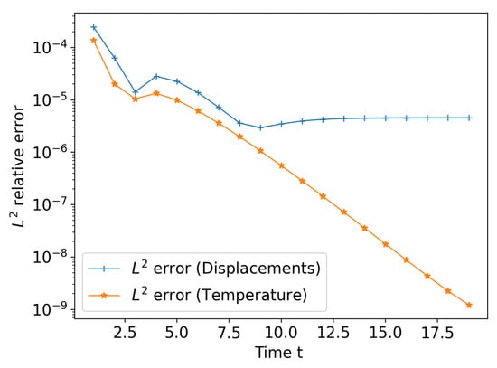
Figure 5.
Evolution of the relative error with respect to the time ().
From the results in Table 2 and Table 3 and, especially, Figure 4, it can be noticed that, by decreasing the thickness ratio , the relative errors present an immediate reduction for fixed times. The convergence rate is of the order and remains constant for increasing time instants. As illustrated in Figure 5, the evolution in time of the -relative error, for fixed , becomes approximately steady after s for the displacement field, while it presents a decreasing trend concerning the temperature field. Besides, even for a relative thickness , at time s, the relative error is close to about 1.89, for the displacement field, and about 5.16, for the temperature field. Hence, the proposed general thermoelastic interface model provides an acceptable solution and it is able to correctly approximate the solution of the three-phase problem. Moreover, the reduced model can also be employed for moderately thick adhesives.
In the sequel, the numerical results obtained by solving the general interface model are presented, considering a relative thickness of . Following the approach by [43], hereinafter, the results are provided using dimensionless variables:
- ,
- ,
where , , and ℓ and V are defined by
Let us notice that the domain is chosen such that , and .
Figure 6 represents the trend of the displacement and temperature , evaluated along on the orthogonal fiber to the mid-plane of the interface at point , for given times. The plot shows that, after the thermal shock, the displacement evolves in opposite directions within the adherents: the composite laminated plate tends to expand and contract itself along the through-the-thickness axis. On the other hand, the temperature field remains constant along the -axis within the adherents, for given times, reaching a steady value after a certain time interval. As expected, the plots also report a jump of the state fields in correspondence of the intermediate layer, and, thus, the adhesive behaves as a soft thermoelastic interface. This is mainly due to the material properties of the adhesive, which are smaller with respect to the those of the adherents.
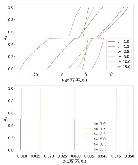
Figure 6.
Displacement and temperature along the -axis, on a fiber , for given times.
Figure 7 illustrates the evolution of the displacement field U and temperature with respect to the time t, at a given point , placed on the bottom face of the composite plate. As expected, the thermal shock induces an oscillatory trend concerning the displacements. Conversely, the temperature evolves to a steady state, corresponding to a constant value, after a sudden increase related to the thermal shock application.
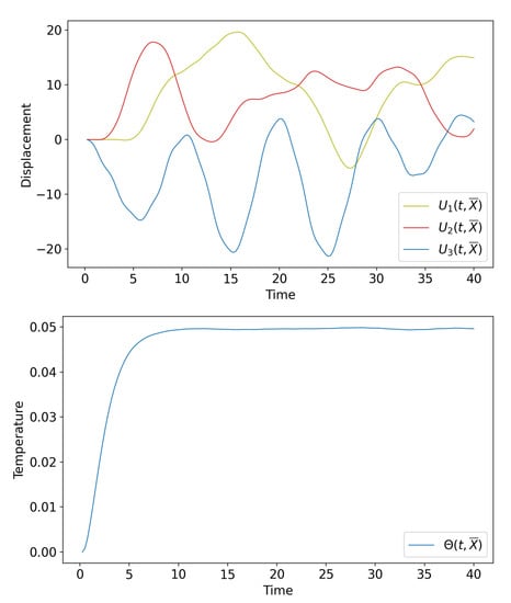
Figure 7.
Displacement field and temperature versus time t, at a given point .
Figure 8 represents the trend of the stresses and , evaluated along on the orthogonal fiber to the mid-plane of the interface at point , for given times. The plot shows that, after the thermal shock, the stress remains constant along the -axis within the adherents. In this particular case, the thermal contribution to is predominant with respect to the elastic one, i.e., : indeed, their diagrams present analogous trends and differ for a constant of proportionality (see Figure 6 and Figure 8). The stress presents an oscillating behavior along inside the adherents, but its contribution is negligible compared with . Moreover, the normal and shear stresses , evaluated at the top and bottom faces of the intermediate layer, are very similar and, thus, their jump almost vanishes. This is typical of soft interface models, in which the thermoelastic state presents a discontinuity, while its conjugated quantities (traction vector and normal heat flow) are continuous across the interface.
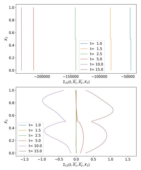
Figure 8.
Stresses and along the -axis, on a fiber , for given times.
Figure 9 shows a comparison between the evolution in time of , at a given point , of a homogeneous three-layer plate, made of aluminum, and the Al/PVC composite plate. Although the thickness ratio is small (), the effect of the adhesive becomes relevant concerning the response of the plate to the thermal shock. The homogeneous plate appears to be stiffer with respect to the composite one, which manifests a significant amplitude and period increase of the motion.
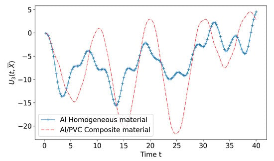
Figure 9.
Evolution in time of at a given point for a homogeneous Al-plate and an Al/PVC composite plate.
7. Concluding Remarks
General imperfect interface conditions are proposed in the framework of coupled thermoelasticity, simulating the thermomechanical behavior of a thin-bonded joint. The approach used to obtain the transmission conditions is based on the asymptotic expansions method. Zero- and higher-order interface models are derived for soft and hard interphases. Following [33], a general transmission law, comprising the two regimes (soft and hard) at the various order, is derived. To assess the validity of the previous asymptotic approach, numerical simulations were developed using a finite element method, which generalizes an analogous methodology to dynamical coupled thermoelasticity, already proposed in [34] in the framework of piezoelectricity. The numerical example consisted of a thermoelastic composite three-layer aluminum plate, with a PVC adhesive, subject to a thermal shock. Two different configurations were considered: the first one consisted of an initial three-phase problem, while the second one took into account the FE discretized form of interface problem (27). The most significant fields (displacement and temperature) and their -relative errors were then computed and compared to test the validity of the proposed interface laws and the accuracy of the asymptotic model. The proposed general thermoelastic interface model provides an acceptable solution and it is able to correctly approximate the solution of the three-phase problem. These findings clearly indicate that the approach of substituting the interphase with the proposed interface law provides a robust modeling for the composite.
Author Contributions
The following statements should be used “Conceptualization, M.S., S.D., R.R. and F.L.; methodology, M.S., S.D., R.R. and F.L.; software, S.D.; validation, M.S. and S.D.; formal analysis, M.S., S.D. and R.R.; investigation, M.S.; data curation, M.S., S.D. and R.R.; writing—original draft preparation, M.S.; writing—review and editing, M.S., S.D., R.R. and F.L.; funding acquisition, R.R. All authors have read and agreed to the published version of the manuscript.
Funding
This research received no external funding.
Institutional Review Board Statement
Not applicable.
Informed Consent Statement
Not applicable.
Data Availability Statement
Not applicable.
Conflicts of Interest
The authors declare no conflict of interest.
References
- Benveniste, Y. The effective conductivity of composites with imperfect thermal contact at constituent interfaces. Int. J. Eng. Sci 1986, 24, 1537–1552. [Google Scholar] [CrossRef]
- Benveniste, Y. Effective thermal-conductivity of composites with a thermal contact resistance between the constituents-nondilute case. J. Appl. Phys. 1987, 61, 2840–2843. [Google Scholar] [CrossRef]
- Kapitza, P.L. Collected Papers of P. L. Kapitza; ter Haar, D., Ed.; reprinted 1965; Pergamon: Oxford, UK, 1941. [Google Scholar]
- Pham Huy, H.; Sanchez-Palencia, E. Phenomenes de transmission à travers des couches minces de conductivité elevée. J. Math. Anal. Appl. 1974, 47, 284–309. [Google Scholar]
- Miloh, T.; Benveniste, Y. On the effective conductivity of composites with ellipsoidal inhomogeneities and highly conducting interfaces. Proc. R. Soc. Lond. A 1999, 455, 2687–2706. [Google Scholar] [CrossRef]
- Hashin, Z. Thin interphase/imperfect interface in conduction. J. App. Phys. 2001, 89, 2261–2267. [Google Scholar] [CrossRef]
- Javili, A.; Kaessmair, S.; Steinmann, P. General imperfect interfaces. Comput. Methods Appl. Mech. Engrg. 2014, 275, 76–97. [Google Scholar] [CrossRef]
- Benveniste, Y. Effective mechanical behaviour of composite materials with imperfect contact between the constituents. Mech. Mat. 1985, 4, 197–208. [Google Scholar] [CrossRef]
- Hashin, Z. Thin interphase/imperfect interface in elasticity with application to coated fiber composites. J. Mech. Phys. Solids 2002, 50, 2509–2537. [Google Scholar] [CrossRef]
- Gurtin, M.E.; Murdoch, A.I. A continuum theory of elastic material surfaces. Arch. Ration. Mech. Anal. 1975, 57, 291–323. [Google Scholar] [CrossRef]
- Yvonnet, J.; Le Quang, H.; He, Q.C. An XFEM/level set approach to modelling surface/interface effects and to computing the size-dependent effective properties of nanocomposites. Comput. Mech. 2008, 42, 119–131. [Google Scholar] [CrossRef]
- Yvonnet, J.; Mitrushchenkov, A.; Chambaud, G.; He, Q.C. Finite element model of ionic nanowires with size-dependent mechanical properties determined by ab initio calculations. Comput. Methods Appl. Mech. Eng. 2011, 200, 614–625. [Google Scholar] [CrossRef]
- Benveniste, Y.; Miloh, T. Imperfect soft and stiff interfaces in two-dimensional elasticity. Mech. Mat. 2001, 33, 309–323. [Google Scholar] [CrossRef]
- Benveniste, Y. A general interface model for a three-dimensional curved thin anisotropic interphase between two anisotropic media. J. Mech. Phys. Solids 2006, 54, 708–734. [Google Scholar] [CrossRef]
- Ciarlet, P.G. Mathematical Elasticity, Vol. II: Theory of Plates; North-Holland: Amsterdam, The Netherlands, 1997. [Google Scholar]
- Serpilli, M.; Lenci, S. Asymptotic modelling of the linear dynamics of laminated beams. Int. J. Solids Struct. 2012, 49, 1147–1157. [Google Scholar] [CrossRef]
- Serpilli, M.; Lenci, S. An overview of different asymptotic models for anisotropic three-layer plates with soft adhesive. Int. J. Solids Struct. 2016, 81, 130–140. [Google Scholar] [CrossRef]
- Furtsev, A.; Itou, H.; Rudoy, E. Modeling of bonded elastic structures by a variational method: Theoretical analysis and numerical simulation. Int. J. Solids Struct. 2020, 182–183, 100–111. [Google Scholar] [CrossRef]
- Furtsev, A.; Rudoy, E. Variational approach to modeling soft and stiff interfaces in the Kirchhoff-Love theory of plates. Int. J. Solids Struct. 2020, 202, 562–574. [Google Scholar] [CrossRef]
- Klarbring, A. Derivation of the adhesively bonded joints by the asymptotic expansion method. Int. J. Eng. Sci. 1991, 29, 493–512. [Google Scholar] [CrossRef]
- Geymonat, G.; Krasucki, F.; Lenci, S. Mathematical Analysis of a bonded joint with a soft thin adhesive. Math. Mech. Solids 1999, 16, 201–225. [Google Scholar] [CrossRef]
- Bessoud, A.L.; Krasucki, F.; Serpilli, M. Asymptotic analysis of shell-like inclusions with high rigidity. J. Elast. 2011, 103, 153–172. [Google Scholar] [CrossRef]
- Ljulj, M.; Tambaca, J. 3D structure – 2D plate interaction model. Math. Mech. Solids 2019, 4, 3354–3377. [Google Scholar] [CrossRef]
- Lebon, F.; Rizzoni, R. Asymptotic analysis of a thin interface: The case involving similar rigidity. Int. J. Eng. Sci. 2010, 48, 473–486. [Google Scholar] [CrossRef]
- Lebon, F.; Rizzoni, R. Asymptotic behavior of a hard thin linear interphase: An energy approach. Int. J. Solids Struct. 2011, 48, 441–449. [Google Scholar] [CrossRef]
- Rizzoni, R.; Dumont, S.; Lebon, F.; Sacco, E. Higher order model for soft and hard elastic interfaces. Int. J. Solids Struct. 2014, 51, 4137–4148. [Google Scholar] [CrossRef]
- Dumont, S.; Rizzoni, R.; Lebon, F.; Sacco, E. Soft and hard interface models for bonded elements. Compos. Part B Eng. 2018, 153, 480–490. [Google Scholar] [CrossRef]
- Lebon, F.; Rizzoni, R. Higher order interfacial effects for elastic waves in one dimensional phononic crystals via the Lagrange-Hamilton’s principle. Eur. J. Mech. A Solids 2018, 67, 57–70. [Google Scholar] [CrossRef]
- Serpilli, M. Mathematical modeling of weak and strong piezoelectric interfaces. J. Elast. 2015, 121, 235–254. [Google Scholar] [CrossRef]
- Serpilli, M. Asymptotic interface models in magneto-electro-thermo-elastic composites. Meccanica 2017, 52, 1407–1424. [Google Scholar] [CrossRef]
- Serpilli, M. Classical and higher order interface conditions in poroelasticity. Ann. Solid Struct. Mech. 2019, 11, 1–10. [Google Scholar] [CrossRef]
- Serpilli, M. On modeling interfaces in linear micropolar composites. Math. Mech. Solids 2018, 23, 667–685. [Google Scholar] [CrossRef]
- Serpilli, M.; Rizzoni, R.; Lebon, F.; Dumont, S. An asymptotic derivation of a general imperfect interface law for linear multiphysics composites. Int. J. Solids Struct 2019, 180–181, 97–107. [Google Scholar] [CrossRef]
- Dumont, S.; Serpilli, M.; Rizzoni, R.; Lebon, F. Numerical Validation of Multiphysic Imperfect Interfaces Models. Front. Mater. 2020, 7, 158. [Google Scholar] [CrossRef]
- Shi, P.; Shillor, M. Existence of a solution to the N dimensional problem of thermoelastic contact. Indiana Univ. Math. J. 1992, 17, 1597–1618. [Google Scholar]
- Khludnev, M.; Kovtunenko, V.A. Analysis of Cracks in Solids; WIT-Press: Southampton, UK; Boston, MA, USA, 2000. [Google Scholar]
- Xu, X. The N-dimensional quasistatic problem of thermoelastic contact with Barbers heat exchange conditions. Adv. Math. Sci. Appl. 1996, 6, 559–587. [Google Scholar]
- Showalter, R.E. Diffusion in poro-elastic media. J. Math. Anal. Appl. 2000, 251, 310–340. [Google Scholar] [CrossRef]
- Miara, B.; Suarez, J.S. Asymptotic pyroelectricity and pyroelasticity in thermopiezoelectric plates. Asympt. Anal. 2013, 81, 211–250. [Google Scholar] [CrossRef]
- Bonaldi, F.; Geymonat, G.; Krasucki, F.; Serpilli, M. An asymptotic plate model for magneto-electro-thermo-elastic sensors and actuators. Math. Mech. Solids 2017, 22, 798–822. [Google Scholar] [CrossRef]
- Renard, Y.; Pommier, J. Getfem++. An Open Source Generic C++ Library for Finite Element Methods; Tech. Rep.; INSA Lyon: Villeurbanne, France, 2002. [Google Scholar]
- Geuzaine, C.; Remacle, J.-F. Gmsh: A 3-d finite element mesh generator with built-in pre- and post-processing facilities. Int. J. Numer. Methods Eng. 2009, 79, 1309–1331. [Google Scholar] [CrossRef]
- Jafarinezhad, M.R.; Eslami, M.R. Coupled thermoelasticity of FGM annular plate under lateral thermal shock. Compos. Struct. 2017, 168, 758–771. [Google Scholar] [CrossRef]
Publisher’s Note: MDPI stays neutral with regard to jurisdictional claims in published maps and institutional affiliations. |
© 2021 by the authors. Licensee MDPI, Basel, Switzerland. This article is an open access article distributed under the terms and conditions of the Creative Commons Attribution (CC BY) license (http://creativecommons.org/licenses/by/4.0/).