Article

Air-to-Air Flight: ANFIS-Assisted Multi-Pack LiPo Battery Charging System for Continuous Flying Missions of UAVs

by
Essam Ali
1,2,*,
Mohamed Abdelrahem
1,3,*,
José Rodríguez
4,
Abdelfatah M. Mohamed
1 and
Alaaeldin M. Abdelshafy
1,2
1
Electrical Engineering Department, Assiut University, Assiut 71515, Egypt
2
Electrical Distribution and Transmission Technology Department, New-Assiut Technological University, New-Assiut, Assiut 71625, Egypt
3
High-Power Converter Systems (HLU), Technical University of Munich (TUM), 80333 Munich, Germany
4
Center for Energy Transition, Universidad San Sebastián, Santiago 8420524, Chile
*
Authors to whom correspondence should be addressed.
Technologies 2026, 14(6), 379; https://doi.org/10.3390/technologies14060379
Submission received: 29 May 2026 / Revised: 16 June 2026 / Accepted: 18 June 2026 / Published: 22 June 2026

Abstract

Continouous unmanned aerial vehicle (UAV) missions are fundamentally limited by Lithium-Polymer (LiPo) battery endurance under intermittent and power-constrained renewable energy conditions. This paper proposes an integrated energy management and charging framework for a photovoltaic (PV)-powered mobile station equipped with a hybrid energy storage system (HESS) and an automated battery replacement (ABR) mechanism. A lexicographic priority-based allocator sequentially serves ABR actuation, multi-slot LiPo charging, and Brushless DC (BLDC) propulsion, while the HESS compensates for PV intermittency. At the charging level, a constraint-aware constant current–constant voltage (CC–CV) strategy is enhanced by an adaptive neuro-fuzzy inference system (ANFIS) trained on optimization-derived labels using battery temperature and its rate of change, thus enabling anticipatory thermal current derating with smooth, discontinuity-free control action. Anti-windup proportional–integral (PI) regulation and bumpless mode transfer ensure stable CC-to-CV transitions. An event-triggered emergency mode accelerates battery readiness via a max-first selection policy. Comparative simulations against a PSO/DE-optimized PID benchmark over a full diurnal PV cycle demonstrate that the ANFIS controller reduces the CC-mode current tracking root-mean-square error (RMSE) by up to 96.9%, delivers higher charge throughput, and lowers battery degradation proxies, including SOC-weighted thermal dose and equivalent full cycles (EFC). The proposed framework reliably sustains continuous charge–swap–recharge logistics under fluctuating renewable generation.

1. Introduction and Related Works

Efficient lithium-ion battery charging using the CC-CV method is necessary for continuous UAV operations, yet it faces limitations in fast and constrained settings. Although most research work revolves around single-cell charging processes, there is a lack of work on multi-pack charging under the constrained, time-varying power-supply conditions encountered in UAV systems.

1.1. Energy Challenges and Power Management in UAV Systems

Unmanned aerial vehicles (UAVs) are increasingly deployed in applications such as surveillance, environmental assessment, precision agriculture, infrastructure inspection, and disaster management [1,2]. Moreover, UAVs have attracted significant interest due to advances in microprocessors, artificial intelligence (AI), sensing technologies, and manufacturing processes, thus enabling the development of more intelligent and capable systems [3].
UAVs rely on battery-powered propulsion due to its simplicity and operational flexibility. Lithium-based batteries, particularly lithium polymer (LiPo) types, are widely used in both recreational and commercial UAVs due to their favorable balance between performance and cost. LiPo batteries are especially suitable for compact UAVs because of their low weight and relatively high energy density [4]. However, the limited capacity of these batteries restricts UAV operating time, necessitating frequent energy replenishment during extended missions [5]. This limitation remains a major barrier to fully autonomous and persistent UAV operations.
Significant efforts have been made to improve battery performance; however, the specific energy of current technologies is still insufficient for long-endurance applications. Furthermore, increasing energy density often introduces trade-offs in safety and reliability [6]. A comprehensive thermal analysis of lithium-ion packs specifically targeting drone applications shows that optimized cooling geometries and phase-change materials can substantially mitigate heat accumulation during high-rate discharge [7], further motivating the need for temperature-aware charging at the ground station.
Alternative energy solutions have therefore been explored in the literature and summarized in the taxonomy diagram shown in Figure 1. Fuel cells offer higher specific energy than conventional batteries [8,9]. In addition, hybrid energy architectures combining batteries, fuel cells, solar panels, and supercapacitors have been proposed to enhance system performance [10]. In such systems, the energy management system (EMS) plays a critical role in coordinating power flow and improving efficiency.
Despite their advantages, fuel cells face challenges such as increased system complexity, hydrogen storage requirements, slow transient response, high cost, and limited infrastructure. Consequently, they are typically used in hybrid configurations with batteries or supercapacitors [11,12,13].
Onboard batteries are rapidly depleted due to propulsion demands and payload requirements. Therefore, autonomous energy replenishment systems are essential to enable UAVs to land, recharge, and resume operation without human intervention [14].
Two main solutions are widely adopted: autonomous charging stations and battery-swapping systems. Charging stations utilize either wireless power transfer or conductive interfaces, while battery-swapping systems reduce downtime through automated replacement mechanisms [15,16,17,18,19,20,21]. A broad survey of powering and charging technologies for UAVs, covering inductive pads, direct-contact connectors, and swapping architectures, further highlights the trade-offs between energy density, alignment tolerance, and mission continuity [22].
Recent research has focused on photovoltaic (PV)-powered charging stations for remote and off-grid applications. While fixed PV stations demonstrate feasibility, mobile PV-based platforms provide greater flexibility by allowing deployment closer to UAV operation zones [23,24]. However, solar intermittency remains a major challenge. To address this issue, hybrid energy storage systems (HESS), combining batteries and supercapacitors, are used to buffer energy fluctuations and ensure stable operation [25]. Recent work on data-driven power management of battery–supercapacitor HESS in solar DC-microgrids confirms that intelligent supervisory strategies can smooth PV intermittency effectively [26].

1.2. Lithium-Ion Charging Techniques and Continuous Energy Supply for UAVs

This subsection reviews prior studies relevant to: (i) lithium-ion/LiPo charging protocols covering both traditional and fast-charging approaches; (ii) constraint-aware and fast-charging methods; (iii) intelligent charging, fuzzy/learning-based controllers including ANFIS; (iv) UAV continuous-mission energy replenishment (docking and exchange). The objective is to position the proposed power-constrained ANFIS-assisted CC–CV strategy within the existing literature and clearly identify the research gap addressed in this work.
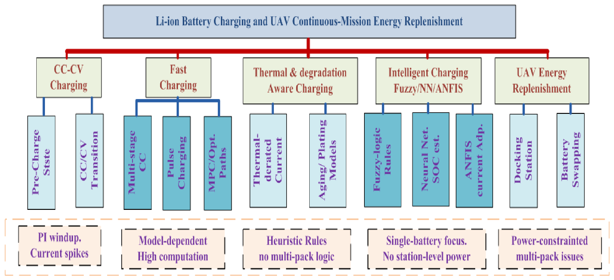
Figure 2 presents a taxonomy of the relevant literature on lithium-ion battery charging strategies and UAV continuous-mission energy replenishment. Five research streams are identified: conventional CC–CV charging, fast-charging protocols, thermal and degradation-aware methods, intelligent fuzzy/neural/ANFIS-based controllers, and UAV docking and swapping systems. Each stream is reviewed with respect to its known limitations; they collectively motivate the proposed ANFIS-assisted, power-constrained supervisory charging approach developed in this work.

1.2.1. Conventional CC–CV Charging and Practical Limitations

Due to its simplicity, reliability, and compatibility with voltage-limited chemistries, the constant current–constant voltage (CC–CV) method remains the dominant industrial charging strategy for lithium-based batteries [27,28,29]. The protocol begins with a low-current pre-charge stage when the battery is deeply discharged, transitions to a constant-current (CC) phase until the terminal voltage reaches its ceiling, and then enters a constant-voltage (CV) phase in which the current gradually tapers to a tail-current threshold.
Despite its widespread adoption, several limitations arise when fast charging or constrained operation is required. First, charging must strictly satisfy safety constraints on voltage, current, and temperature to prevent degradation and hazardous conditions. Second, aggressive current profiles aimed at reducing charging time can accelerate aging mechanisms such as lithium plating, particularly under low-temperature or high-voltage conditions. Third, practical implementation issues, including current spikes during CC↔CV transitions and proportional–integral (PI) controller windup, may compromise stability and safety [30]. A recent evaluation of CC–CV charging under different transition regimes further quantifies how the switching threshold voltage and the SOC at transition jointly influence charge time, temperature rise, and cycle life [31], reinforcing the need for debounced, hysteresis-based mode supervisors of the type proposed in this work.

1.2.2. Fast-Charging Protocols Beyond CC–CV Charging

Numerous works extending the single-stage CC–CV protocol have been reported and are aimed at minimising charge time while limiting battery aging.
A widely used class is the multi-stage constant-current (MSCC) controller, where the charging current is scheduled in steps or ramps as a function of voltage, SOC, or time. These protocols can reduce charge time and temperature rise compared with a single high CC level [32]. Coyote-optimization-algorithm (COA) based search of SOC-transition points and current levels for MSCC charging is reported to reduce temperature rise by up to 46% while cutting charge time by 4% [33], without requiring electrochemical models. A PSO-guided multi-stage constant-current constant-voltage (MMSCC-CV-PSO) strategy further reduces charging time by 21% and energy consumption by 15% compared with standard CC–CV, while providing online monitoring of lithium plating [34]. addedParallel aging-optimized MSCC protocols based on three-electrode measurements confirm that the choice of SOC-transition boundaries critically governs both plating risk and long-term capacity retention [35].
The second class of considerable interest is pulse charging, in which brief current pulses and rest periods are interleaved to reduce polarization and control thermal rise. Results vary depending on battery chemistry and pulse timing [36].
Optimal charge paths are obtained through equivalent-circuit or electrochemical models by maximising cost functions that trade off charging time, energy loss, temperature rise, or estimated aging [37]. Model Predictive Control (MPC) and related predictive frameworks enforce constraints explicitly and handle multivariable electro-thermal coupling [38]. An MPC-based optimal fast-charging strategy for NMC cylindrical cells at different temperatures minimizes temperature while maximising SOC simultaneously [39], highlighting the suitability of predictive frameworks for thermal-safety-aware charging.
Although fast-charging literature is rich and varied, deployment under limited computation and uncertain conditions remains challenging. Many model-based techniques require parameter identification and internal state observability—requirements that are difficult to satisfy in the multi-pack, PV-powered station context of this work.

1.2.3. Temperature-Aware and Degradation-Aware Charging

Temperature is a critical constraint in lithium battery charging because it affects kinetics, internal resistance, heat generation, and degradation mechanisms. Some previous work proposed thermal-derated charging where current limits depend on measured temperature, mostly by means of heuristic rules, lookup tables, or electro-thermal models [40]. Plating-risk indicators, side-reaction models, or empirical aging maps as degradation-aware charging may further decrease the current under conditions associated with high degradation rates [41]. An electrochemical-thermal-life-model-based multi-stage CC strategy (C-MCC) that dynamically adjusts current using real-time negative electrode overpotential and temperature as dual constraint boundaries achieves over 2C-rate effective charging below SOC 0.64 with only 5% modeling error [42]. A high-power SOC-range-segmented strategy that combines temperature constraint with key SOC-segment targeting provides insight into managing temperature rise during aggressive fast charging [43]. These approaches collectively emphasize that practical fast charging is not solely an electrical control problem; it is inherently electro-thermal and must incorporate predictive safety margins—an insight directly embodied in the ANFIS thermal limiter of this work.

1.2.4. Intelligent Charging: Fuzzy Logic, Neural Networks, and ANFIS

Intelligent control methods have been widely proposed to handle the nonlinear dynamics of battery systems, particularly under uncertain operating conditions and incomplete system knowledge.
Fuzzy-logic-based chargers map measurements such as voltage error, temperature, and SOC to action commands or mode-switching decisions using linguistic rules. The reported benefits include smooth control actions and robustness to modeling uncertainty [44]. Fuzzy-logic controllers have also been applied for DC bus voltage stabilization in PV–fuel-cell–battery–supercapacitor hybrids, demonstrating the broad applicability of rule-based controllers in energy management [45].
Methods based on neural networks have been applied for SOC estimation and, in certain cases, direct charging control or profile generation [46]. Recurrent architectures, including long short-term memory (LSTM) and dual-input networks, have demonstrated superior accuracy in online SOC tracking across the full battery lifetime [47]. Data-driven Koopman MPC approaches and LSTM–TCN-based energy management further show the potential of machine-learning methods in real-time microgrid HESS control [48].
Adaptive Neuro-Fuzzy Inference Systems (ANFIS) combine fuzzy rule structures with data-driven learning of parameters, enabling compact nonlinear function approximation while preserving interpretability through membership functions and rules [49]. An early but foundational ANFIS-based SOC estimator using hybrid learning (gradient descent and least-squares estimation) with Sugeno fuzzy rules achieved better interpolation performance than back-propagation ANNs [50], establishing ANFIS as a credible tool for battery management. An ANFIS-optimized closed-loop charging strategy in MATLAB/Simulink (Appendix B).
Demonstrates shorter charge times and improved life compared with CC–CV and PID-feedback approaches [51], directly motivating the ANFIS-based derating approach of the present work. ANFIS has also been applied to active cell-balancing control, where 7 × 7 membership functions with hybrid least-squares/back-propagation training achieve near-ideal voltage balancing across multiple lithium cells [52]. In energy management for hybrid electric vehicles, an ANFIS-based controller sustains optimal battery charge while coordinating biofuel and electric sources [49]. However, most intelligent charging studies focus on a single battery and do not explicitly address station-level power constraints, multi-pack allocation, or robust supervisory logic for mode switching.

1.2.5. UAV Continuous-Mission Energy Replenishment

Continuous UAV operations encourage adoption of self-managed replenishment systems, primarily via (i) docking stations (wired or wireless) and (ii) battery swapping.
Many studies on docking/charging stations have addressed landing accuracy, battery-charging connector design, station siting, and wireless charging implementability and efficiency [53,54]. A decade-long review of UAV docking stations identifies key evolving themes: precision landing, mechanical robustness, and energy transfer efficiency [53]. Building-integrated PV systems with wireless inductive transfer enable drone autonomous energy replenishment without precise alignment [23]. AutoCharge demonstrates a portable ground-station charging tether with circular magnetic connectors achieving repeatable docking and undocking and is validated in a 10 h perpetual quadrotor flight experiment [55]. A cloud-orchestrated autonomous charging station that leverages CC–CV profiles and a BMS for LiPo cell balancing, with a cloud-stored battery profile and GPS-based dock navigation, underlines the scalability of multi-drone CC–CV systems [56]. A comprehensive review of autonomous UAV recharging systems for multirotor platforms catalogs key design choices—landing platforms, mechanical alignment aids, and charging electronics—and identifies power management as an underexplored area [57].
Battery-swapping systems reduce turnaround time but increase the complexity of the mechanical system and associated logistics (inventory control, part alignment, and interlock safeguards) [58,59]. An energy self-controlled solar-powered base station for automatic battery replacement with independent UAV take-off and landing confirms the feasibility of fully autonomous solar-powered swapping [60]. A comparative study of energy sources, docking stations, and wireless charging for quadrotor UAVs establishes that battery swapping offers the fastest turnaround while demanding the most robust mechanical design [19].
Multi-UAV scheduling and battery swapping optimization in UAV-enabled mobile edge computing formulates optimal flight-speed and swap-time strategies to maximize task throughput under power constraints [59]. Aerial swarm applications impose additional requirements on replenishment logistics, as the number of drones and their mission diversity must be reflected in charging priority and scheduling policies [61].
From a control-systems perspective, UAV stations often operate under limited power sources—mobile generators, solar/battery microgrids, or shared facility circuits—and must charge multiple packs simultaneously, making station-level power assignment and robust charging control critical to operational throughput.

1.2.6. Positioning of the Proposed EMS Within State-of-the-Art Approaches

The recent developments in energy management systems (EMS) have been directed toward different optimization objectives depending on the application domain. Communication-oriented EMS frameworks based on the Robot Operating System (ROS 2) primarily emphasize real-time performance and reliable operation under asynchronous communication and varying node update rates, rather than optimal power allocation [62]. Hierarchical economic MPC approaches have gained significant attention in microgrid applications due to their ability to achieve economically optimal energy dispatch across multiple time scales [63]. Rule-based Stateflow controllers for DC microgrids with high renewable penetration provide a computationally lightweight alternative that enforces simple priority rules without an optimization solver [64]. Metaheuristic techniques, such as PSO, have been successfully applied in dual-energy electric vehicles to optimize propulsion efficiency and power distribution among energy sources [65]. AI-augmented HESS microgrid controllers that combine ANN-based forecasting with MPC-style coordination have been shown to improve power quality and reduce storage cycling stress [66].
In contrast to these approaches, the EMS proposed in this work is specifically designed for a renewable-powered UAV charging and battery-swapping station, where operational priorities are governed by mission-critical and safety constraints. The system must simultaneously account for intermittent PV generation, HESS limitations, emergency battery-swapping demands, scheduled mechatronic operations, and temperature-dependent charging constraints. Accordingly, the proposed EMS adopts a priority-based (lexicographic) control framework, in which higher-priority constraints are satisfied before allocating resources to lower-priority tasks. Such supervisory strategies have been widely recognized as effective in hybrid energy systems where constraint satisfaction and real-time responsiveness are more critical than global optimality [67].
A comparison of the proposed approach with key state-of-the-art EMS and charging strategies is summarized in Table 1.

1.3. Novelty and Contribution

The novelty of the present work lies in the development of a unified energy management and charging framework that explicitly integrates the following four contributions within a single control architecture:
  • Debounced CC–CV supervisory controller:A hysteresis-based mode supervisor with freeze timers prevents mode chatter near the voltage ceiling, addressing known stability issues during CC↔CV transitions [30,31].
  • Anti-windup PI current and voltage regulation with bumpless transfer: Conditional integration suspension and integrator pre-loading at CC→CV entry eliminate current spikes and integrator windup, practical aspects that are often overlooked in the charging literature despite their critical importance for stable and reliable charger operation [30].
  • ANFIS-based temperature-dependent current derating module: A first-order Sugeno ANFIS trained on optimization-derived labels maps instantaneous battery temperature and its rate of change onto a smooth, continuous derating factor, enabling predictive thermal regulation without the abrupt transitions observed in rule-based strategies [40,41]. While previous studies have employed fuzzy logic or data-driven techniques for single-battery management [49,50,52], the integration of ANFIS-based nonlinear current derating within a multi-load, priority-driven EMS represents a key advancement.
  • Priority-driven power allocation strategy for simultaneous multi-pack charging under a strict power constraint: Unlike conventional EMS approaches that rely on a single scalar optimization objective, the proposed method adopts a lexicographic (priority-based) decision strategy, ensuring that mission-critical operations are always satisfied before allocating resources to lower-priority tasks. Most existing advanced charging strategies—whether model-based or intelligent—primarily consider single-battery systems and do not incorporate explicit station-level power constraints for multi-pack charging [32,33,39].
A further distinguishing contribution is the incorporation of an event-triggered emergency charging policy that dynamically reallocates power in response to urgent battery replacement requests, ensuring rapid preparation of ready-to-use packs and directly supporting continuous UAV mission operation—a capability not addressed in traditional EMS frameworks [53,57].
It is important to note that, unlike economic MPC-based approaches [38,63], the proposed EMS does not aim to achieve global optimality with respect to a predefined cost function. Instead, it achieves priority-optimal and constraint-consistent operation, where optimality is defined in terms of satisfying a hierarchy of operational requirements under limited and time-varying energy availability. This formulation is more suitable for safety-critical and logistics-driven applications, where guaranteeing feasibility and service continuity is often more important than minimising a scalar objective [67].
The paper is organized as follows: Section 2 presents the proposed mechatronic system, Section 3 details the charging system design, Section 4 derives the current tracking error equations for temperature-constrained operation, Section 5 discusses the obtained results approving the validity and effectiveness of the proposed priority-based energy management framework and the ANFIS-assisted charging strategy, Section 6 demonstrates the conclusions, and Section 7 summarizes the challenges, limitations, and future work.

2. The Proposed Mechatronic System

The core of the proposed system is a 50 V DC bus, which interconnects all primary components. A HESS, comprising a Nickel–Metal Hydride (NiMH) battery and a Super-Capacitor (SC), supplies and regulates DC-bus power and voltage. Each HESS element interfaces with the DC bus through a dedicated bidirectional DC/DC converter, enabling precise control over charge and discharge cycles. The main electrical load consists of LiPo battery packs for UAV charging (shown in Figure 3), which require carefully managed CC-CV profiles. Additional significant loads include the Brushless DC (BLDC) motors that drive the mobile station’s movement and the actuators for the automatic battery replacement system. The system parameters configuration is shown in Table 2.
The SC has high power density, short response time, and is more suitable for transient power demands, while the NiMH battery has high energy density, slower response, and provides long-term energy balance. The LiPo batteries are treated as primary loads requiring controlled CC–CV charging profiles, while the ABR platform motors and the mobile-station drive motors are the secondary loads. The task management system is proposed in our previous work in [24], while an ABR mechanism and the LiPo battery CC-CV charging technique are proposed in [58] and illustrated in Figure 3. The equations of current trackers are developed in Section 4, which are employed during the temperature-constrained control mode of the CC–CV charging algorithm.
The paper presents a design for controlling the voltage and power of the DC bus when there are fluctuations in the source of power and the load demand in the suggested mechatronic system. An energy management scheme that prioritizes the distribution of power among different parts of the system has been proposed in order to maintain a stable and reliable working condition even under varying situations. The design includes the adaptive current reference scheme of the NiMH battery and the SC that allows exchanging power in order to regulate the voltage of the DC bus. Moreover, the current management scheme in which the thermal constraint is considered has also been applied.
In the current study, the system is designed for a single UAV. However, the proposed framework can be extended to a swarm of UAVs by scaling up the charging station’s capacity—namely, the PV generation and energy storage of the mobile charging unit. In this extended scenario, the supervisory charging logic incorporates a priority-based scheduling mechanism. Battery packs are prioritized according to mission urgency, determined by their state of charge (SOC) and the number of UAVs nearing critically low charge levels. The system allocates charging resources to the highest-priority battery packs to ensure mission continuity.

3. Proposed ANFIS-Assisted Power-Constrained CC–CV Charging Technique

3.1. Overview

The proposed charging framework addresses three control objectives for a PV–HESS-powered UAV docking station: (i) charge each LiPo pack safely within voltage, current, and temperature limits; (ii) ensure the total power drawn by all active packs never exceeds the available station power; (iii) produce smooth, spike-free current commands during mode transitions and source-power fluctuations. To meet these objectives the framework integrates three layers: a debounced CC–CV supervisory controller, an ANFIS-based temperature-dependent current limiter, and a priority-driven power allocator.

3.2. Priority-Based Power Management

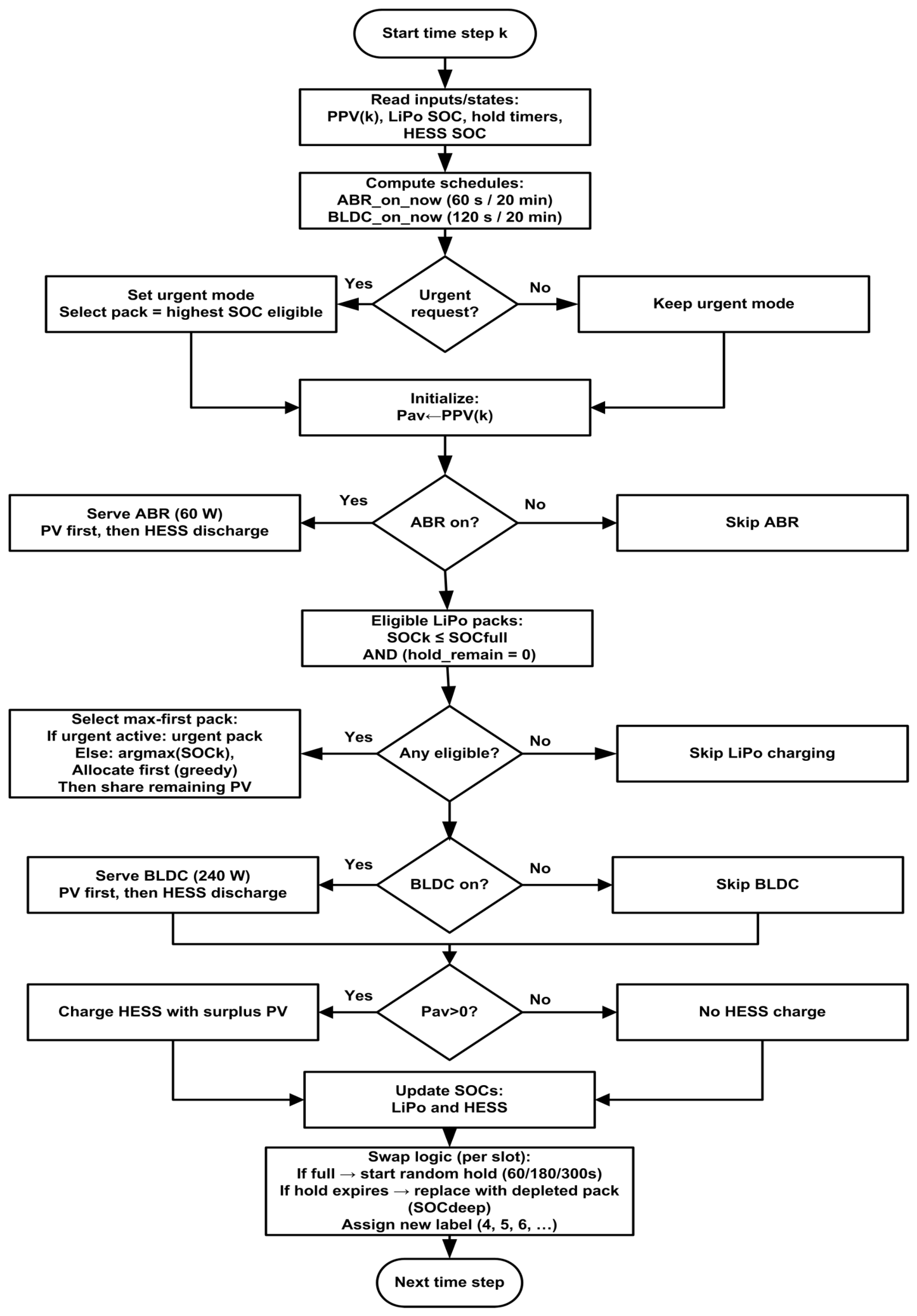
At each discrete time step k the supervisory controller allocates the available PV–HESS power P av ( k ) among loads according to a strict lexicographic hierarchy, summarized in Table 3 and detailed in Algorithm 1. The flowchart is shown in Figure 4.
Algorithm 1 Priority-Based Power Management at Time Step k
Require:  P PV ( k ) , { SOC i ( k ) , hold_remain i ( k ) } i = 1 N , SOC HESS ( k ) , u ABR ( k ) , u BLDC ( k ) , Urgent_flag
Ensure:  { P i ( k ) } , P HESS ( k ) , { SOC i ( k + 1 ) } , SOC HESS ( k + 1 )
       Step 1: Initialize available power
  1:
P av P av ( k ) = P PV ( k ) P ABR + P mov ± P HESS                                                                   (1)
Step 2: Priority 1: ABR stepper motors
  2:
if  u ABR ( k ) = 1  then
  3:
       P ABR ( k ) P ABR , req ;    P av P av P ABR ( k )                                                                        (2)
  4:
else  P ABR ( k ) 0
  5:
end if
Step 3: Priority 2—LiPo charging (max-first)
  6:
E ( k ) { i SOC i ( k ) < SOC full hold_remain i ( k ) = 0 }
  7:
if  E ( k ) Ø  then
  8:
       i p arg max i E ( k ) SOC i ( k )                                                                                              (3)
  9:
       P i p ( k ) min P av , min ( P pack , max , I pack , max V ^ i p ( k ) ) ;    P av P av P i p ( k )                       (4)
10:
      for  j E ( k ) { i p }  do
11:
             P j ( k ) min P av | E ( k ) | 1 , P j max ( k )                                                                                   (5)
12:
      end for
13:
       P LiPo ( k ) i = 1 N P i ( k ) ;    P av P av P LiPo ( k )                                                                   (6)
14:
else  P LiPo ( k ) 0
15:
end if
Step 4: Priority 3—BLDC propulsion
16:
if  u BLDC ( k ) = 1  and  P av > 0  then
17:
       P BLDC ( k ) min ( P BLDC , req , P av ) ;    P av P av P BLDC ( k )
18:
else  P BLDC ( k ) 0
19:
end if
Step 5: Priority 4—HESS surplus/deficit
20:
if  P av > 0  then
21:
       P HESS , ch ( k ) min ( P av , P ch , max )                                                                                        (7)
22:
else
23:
       P def ( k ) P ABR + P LiPo + P BLDC P PV ;    P HESS , dis ( k ) min ( P def , P dis , max )                      (8)
24:
end if
Step 6: SOC updates and battery swapping
25:
for  i = 1  to N do
26:
       SOC i ( k + 1 ) SOC i ( k ) η Δ t Q n I i ( k )                                                                               (A14)
27:
      if  SOC i ( k + 1 ) SOC full  then
28:
            Set t hold { 60 , 180 , 300 }  s; mark slot i non-eligible
29:
      else if  hold_remain i ( k ) = 0  and slot was in hold then
30:
             SOC i SOC dep ; assign new sequential label
31:
      end if
32:
end for
33:
Update SOC HESS ( k + 1 )

3.2.1. Available Power Initialization

The available power is initialized as
P av ( k ) = P PV ( k ) P ABR + P mov ± P HESS
and is decremented sequentially as each priority level is served.
P ABR ( k ) = u ABR ( k ) P ABR , req ,
where u ABR ( k ) { 0 , 1 } is the ABR activation flag ( u ABR = 1 when the UAV is docked, 0 during flight).

3.2.2. LiPo Charging Allocation (Max-First)

A slot is eligible if SOC i ( k ) < SOC full and hold_remain i ( k ) = 0 . The priority pack index is selected as
i p = arg max i E ( k ) SOC i ( k ) ,
where E ( k ) is the eligible set. The allocated power is
P i p ( k ) = min P av , 1 ( k ) , min ( P pack , max , I pack , max V ^ i p ( k ) ) ,
and the remaining power is shared equally among competing packs:
P j ( k ) = min P av , 2 ( k ) | E ( k ) | 1 , P j max ( k ) , j E ( k ) { i p } .
The total LiPo charging power is:
P LiPo ( k ) = i = 1 N P i ( k ) .

3.2.3. HESS Operation

After all scheduled loads are served, surplus or deficit power is handled by the HESS:
P HESS , ch ( k ) = min ( P av , 4 ( k ) , P ch , max ) , P av , 4 ( k ) > 0 , 0 , otherwise ,
P HESS , dis ( k ) = min ( P def ( k ) , P dis , max ) , P def ( k ) > 0 , 0 , otherwise ,
where P def ( k ) = P load , total ( k ) P PV ( k ) . The overall power balance is
P PV ( k ) + P HESS , dis ( k ) = P ABR ( k ) + P LiPo ( k ) + P BLDC ( k ) + P HESS , ch ( k ) + P loss ( k ) .

3.3. ANFIS Temperature Limiter

To ensure thermal safety, the CC current limit for pack k is
I CC , max , k ( T k ) = min I max , abs , α ( T k ) I max , base , k ,
where α ( T ) [ 0 , 1 ] is a temperature-dependent derating factor computed by a first-order Sugeno ANFIS with inputs T k and T ˙ k = d T / d t (9 rules, 3 × 3 generalized bell-shaped membership functions). Incorporating T ˙ k enables anticipatory derating before the thermal knee is reached. The ANFIS output is clipped to the admissible range:
α ( T k ) = clip α ANFIS ( T k ) , 0 , 1 .
If T k T max , the pack enters FAULT mode and I ref , k = 0 until the temperature falls below the limit.

3.4. Debounced CC–CV–DONE Supervisor

Each pack is governed by a mode variable m k { CC , CV , DONE , FAULT } . Hysteresis margins V hyst and hold timers t hold CC CV , t hold CV DONE prevent mode chatter near the voltage ceiling. During CV mode a PI voltage controller with conditional anti-windup and bumpless initialization (integrator pre-loaded at CC→CV entry) regulates the pack voltage to V max , k . Full derivations of the PI law, anti-windup scheme, and bumpless transfer are provided in the Appendix A.

3.5. Power Allocator and Reference Smoothing

The supervisory allocator runs at period T sup = 1 s. For each eligible pack it computes a desired current I des , k and assigns the priority pack up to its thermal-limited demand; remaining power is shared equally. A proportional scaling factor s ( t ) = min ( 1 , P max ( t ) / P need ( t ) ) enforces the global power constraint k V ^ k I ref , k P max ( t ) . Allocated commands are smoothed by a slew-rate limiter followed by a first-order filter ( τ I = 0.30 s) to suppress current spikes at supervisory updates and mode transitions.

4. ANFIS vs. PID Temperature-Limited Current Tracking Equations

In this section, the equations governing the current trackers are derived and applied within the temperature-constrained control mode of the CC–CV charging algorithm. Two control strategies are implemented and evaluated: the first is based on an ANFIS, while the second relies on a conventional PID controller. Both controllers incorporate temperature-dependent limits on the charging current to prevent overheating while ensuring accurate current set-point tracking. The two control strategies are formulated using comparable mathematical frameworks, thereby enabling a straightforward and fair comparison between them.

4.1. ANFIS Rule Base, Mathematical Formulation, and Architecture

For the purposes of this task, an ANFIS architecture is used for adaptive computation of the current derating factor. It should be noted that ANFIS refers to the Adaptive Neuro-Fuzzy Inference System, which uses a first-order Sugeno fuzzy inference system due to its high accuracy and the efficiency of the calculations (Table 4).
The ANFIS uses two input variables, namely the temperature of the battery T and its time derivative d T / d t . Both parameters are needed since one provides information about the temperature at the current moment, whereas the other describes how the temperature changes over time. The output parameter is the current derating factor α [ 0 , 1 ] , which affects the intensity of the allowable current.
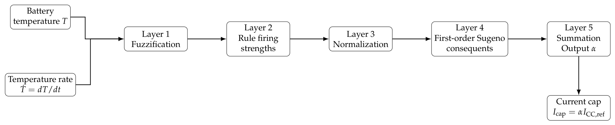
The ANFIS structure used in this work consists of five layers as shown in Figure 5. In Layer 1, the input variables, namely the battery temperature T and its rate of change T ˙ , are fuzzified through generalized bell-shaped membership functions. In Layer 2, the firing strength of each fuzzy rule is computed as the product of the corresponding membership grades. In Layer 3, the firing strengths are normalized. In Layer 4, each rule output is evaluated using a first-order Sugeno consequent of the form f i = p i T + q i T ˙ + r i . Finally, in Layer 5, the overall ANFIS output is obtained as the weighted summation of all normalized rule outputs, producing the derating factor α used to limit the charging current.

4.2. ANFIS-Based Temperature Limiter

This subsection discusses the ANFIS-driven temperature constraints that are employed in the adaptive management of the maximum permissible charging current. The ANFIS maps thermal-based input variables onto the current limiting factor to embed non-linear responses and uncertainties that are difficult to model explicitly. This limiter achieves a smooth reduction in the charging current upon nearing-over temperature thresholds.

4.2.1. ANFIS Output (Derating Factor)

Equation (12) specifies the ANFIS output as a temperature-dependent derating factor α k ( T k ) , ranging between 0 and 1, which scales the available charging current based on the measured temperature T k .
α k ( T k ) = ANFIS ( T k ) , 0 α k 1
For Sugeno fuzzy inference systems with fixed consequent values c r , the ANFIS output is computed as per (13), where α k ( T k ) is represented as the weighted average of the fixed consequent values cr, normalized by the sum of the firing strengths w r ( T k ) of each fuzzy rule.
α k ( T k ) = r = 1 R w r ( T k ) c r r = 1 R w r ( T k ) .

4.2.2. Temperature-Limited Current Cap

The Formula (14) specifies the thermal-limited current cap I k cap ( T k ) as an output of the ANFIS-derived derating factor α k ( T k ) and the nominal CC constant current reference I ref , k CC . In the case of an increase in temperature and a decrease in α k ( T k ) to values lower than 1, the allowable charging current decreases proportionally while maintaining the structure of the CC charging mode.
I k c a p ( T k ) = α k ( T k ) I r e f , k C C .

4.3. ANFIS Training Using Optimization-Derived Labels

To ensure a fair and performance-oriented comparison with the conventional PID temperature limiter, the proposed ANFIS controller is trained using optimization-derived supervisory labels rather than heuristic fuzzy rules. The objective is to learn an optimal temperature-aware current derating policy that maximizes charging throughput while strictly respecting thermal safety constraints.
The ANFIS is formulated with two inputs, namely the instantaneous battery temperature T k and its temporal rate of change T ˙ k , and a single output, the normalized current derating factor α k [ 0 , 1 ] . Incorporating the temperature derivative enables anticipatory control action, allowing the controller to mitigate thermal overshoot before critical thresholds are reached.
Two linguistic input variables (low, medium, high) are used for the representation of each input parameter by means of the GBMF. A generalized bell-shaped membership function (GBMF) was chosen because it has smooth transition areas. Thus, there will be nine ( 3 × 3 ) fuzzy rules. A linear output membership function is applied in order to describe the nonlinear dependence in a fuzzy way.
The generation of the training set involved an offline process where a grid sampling approach was adopted across the entire operating range of inputs. In particular, the temperature T was sampled over a range of values from 35 °C to 55 °C, while its derivative d T d t was sampled over the range from −0.35 °C/s to 0.35 °C/s. This yielded approximately 4000–5000 input–output data pairs for ANFIS training. The targets for output data were computed using a physics-based model, based on the assumption that a progressive reduction in current should be applied when the temperature value increases toward its upper limit. Furthermore, negative temperature derivatives are rewarded, whereas positive temperature derivatives are penalized.
ANFIS was trained using a hybrid learning method involving least square estimation of consequent parameters and a gradient descent for premise parameters. Data sets were divided into two groups for training (75%) and testing (25%) to avoid overfitting and to guarantee generalizability capabilities during training.
This approach led to a smooth, nonlinear and continuous function that maps thermal state variables onto the maximum allowable charging current, avoiding any discontinuities in control policy implementation. In addition, taking into account not only temperature but also its rate of change allows for prediction-based thermal regulation.
Training labels α k are generated offline by solving a one-step constrained optimization problem for each sampled thermal state. For a given input pair ( T k , T ˙ k ) , the optimal derating factor is obtained as
α k = arg min α [ 0 , 1 ] J ( α ) ,
where the cost function is defined as
J ( α ) = w I ( 1 α ) 2 + w K max 0 , T k + 1 T knee 2 + w D max 0 , T ˙ k 2 + w M max 0 , T k + 1 T max 2 .
The first term promotes aggressive charging by penalizing unnecessary current reduction. The second term softly penalizes operation beyond the derating knee temperature T knee , while the third term discourages rapid temperature rise by accounting for the instantaneous temperature gradient. The final term acts as a hard constraint to prevent exceeding the maximum allowable temperature T max . The cost function weights are empirically tuned as w I = 120 (derating penalty), w K = 3000 (soft thermal limit above T knee ), w D = 0.30 (heating rate penalty), and w M = 2 × 10 5 (hard thermal limit above T max ).
The battery temperature evolution is modeled using a first-order lumped thermal model that accounts for Joule heating and heat dissipation to the ambient environment. The temperature at the next time step is expressed as
T k + 1 = T k + Δ t · 1 C th I k 2 R int T k T amb R th ,
where T k (°C) is the battery temperature at time step k, Δ t (s) is the sampling interval, C th (J/°C) is the thermal capacitance, R th (°C/W) is the thermal resistance, R int ( Ω ) is the internal resistance of the battery, I k (A) is the charging current, and T amb (°C) is the ambient temperature.
The first term inside the brackets represents heat generation due to Joule losses, while the second term accounts for convective heat dissipation. This simplified lumped-parameter model provides a computationally efficient representation of the thermal dynamics suitable for real-time control applications.
(1)
Base charging current reference (CC-CV)
The equations in (18)–(20) determine the current reference base I k base based on the standard CC-CV charging protocol. In CC mode, the base of reference current is adjusted to the designed nominal constant current reference I ref , k CC , as shown in (18). As the terminal voltage approaches the upper limit, the controller transitions to the CV mode, where the tracking error in voltage e v , k ( t ) is expressed in terms of the maximum allowable terminal voltage V max , k , as shown in (19). Then, the I k base current is set employing a PI voltage controller, with an output bounded to be between zero and I ref , k CC , as shown in (20).
  • CC mode.
I k b a s e = I r e f , k C C .
  • CV mode (voltage PI control).
e V , k ( t ) = V m a x , k V k ( t ) ,
I k b a s e ( t ) = sat ( K p V , k e V , k ( t ) + K i V , k e V , k ( t ) d t , , 0 , I r e f , k C C ) .
(2)
Apply temperature limitation (common to ANFIS and PID)
I k l i m ( t ) = min I k b a s e ( t ) , I k c a p ( t ) .

4.4. PID-Based Temperature Limiter

In this subsection, a PID-driven temperature limiter will be defined as a benchmark-for-comparison controller. The temperature-based tracking error is represented by (22), where the temperature error is determined by the desired temperature setpoint T set . The system is regulated by the PID controller whose output is given by (23) based on the temperature error. The normalized derating factor is utilized to map the output of the PID controller, as given by the saturation function in (24), to guarantee the acceptable range [ 0 , 1 ] of the factor. Equation (25) gives the temperature-limited current cap, which is obtained by multiplying the constant current reference by the derating factor, thus keeping the standard CC-CV charging paradigm.
  • Temperature error.
e T , k ( t ) = T s e t T k ( t ) .
  • PID output (unsaturated).
u k ( t ) = K p T , k e T , k ( t ) + K i T , k e T , k ( t ) d t + K d T , k d e T , k ( t ) d t
  • Derating factor (saturation).
α k P I D ( t ) = sat u k ( t ) , 0 , 1 .
  • PID temperature-limited current cap.
I k c a p ( t ) = α k P I D ( t ) I r e f , k C C .

4.5. Power-Limit Allocation (Proportional Scaling Used in the Proposed Technique)

The mechanism of power limit allocation is explained in the following equations, which are used to enforce the global source power constraint while maintaining the proportionality coefficient of the current demand. The total power needed to supply all the battery packs constrained by temperature and/or mode constraints is determined firstly based on the sum of the product of the limited current and the corresponding terminal voltage across all [acks as it is written in (26). A scaling factor is used if the total power demand is greater than the supply source power P max ( t ) ; this scaling factor is used to uniformly reduce all the current references in (27). The commanded currents are obtained by scaling the limited current references by the scaling factor in (28).
Define the required power to meet all limited references:
P need ( t ) = k = 1 N I k l i m ( t ) V k ( t ) .
With available source power P max ( t ) , the proportional scaling factor is:
s ( t ) = min 1 , P max ( t ) P need ( t ) .
The commanded currents after allocation are:
I k c m d ( t ) = s ( t ) I k l i m ( t ) .

4.6. Current-Loop Tracking Plant (First-Order, Used to Evaluate Tracking)

The current loop tracking plant is assumed to be a first-order system, which signifies the inner closed-loop response of the inner control level. The dynamic evolution of the measured current i k (t) is described in Equation (29)
d i k ( t ) d t = I k c m d ( t ) i k ( t ) τ I .
where I k c m d ( t ) defines the commanded current and τ I represents the time constant of the current loop. The inner control loop being significantly faster than the outer loops is the main assumption of this controller and can be modeled approximately by a first-order system. The model is primarily utilized for assessing the current loop tracking performance, its bandwidth limits, and its transient responses.

4.7. Tracking Error Metrics (vs. Temperature-Limited Reference)

The tracking errors are determined in relation to a temperature-limited reference. The instantaneous tracking error is expressed as the offset between the actual current value and the thermal-limited reference value. Two main tracking metrics are measured to calculate the tracking errors over a time period, the Root-Mean-Square Error (RMSE), which is a weighted indicator of the tracking errors, and the Mean Absolute Error (MAE), which is linearly proportional to the tracking accuracy. These two metrics are paired to provide a complete picture of the tracking accuracy.
e I , k ( t ) = i k ( t ) I k l i m ( t ) .
Common performance metrics:
RMSE k = 1 T 0 T e I , k 2 ( t ) d t ,
MAE k = 1 T 0 T | e I , k ( t ) | d t .

5. Results and Discussion

The simulation results presented in this section validate the proposed priority-based energy management framework and the ANFIS-assisted CC–CV charging strategy under a full diurnal PV cycle representing realistic agricultural UAV deployment conditions. The results are organized to demonstrate three principal outcomes. First, the proposed supervisory allocator maintains strict priority compliance for all mission-critical operations—including ABR actuation and LiPo charging—even during PV power shortages, by leveraging controlled HESS discharge to cover transient power deficits. Second, the HESS exhibits physically consistent signed power behavior throughout the entire operating window, with positive net power during surplus-driven charging intervals and negative net power during discharge-driven compensation periods, confirming the correctness and stability of the bidirectional energy management logic. Third, the proposed architecture improves the renewable energy utilization and operational reliability of the UAV ground-support station by coordinating PV generation, HESS buffering, and multi-slot battery charging within a single unified control framework. A comparative analysis between the ANFIS-based and PID-based thermal current limiters is subsequently presented to quantify improvements in tracking accuracy, thermal stress mitigation, and battery lifetime preservation.
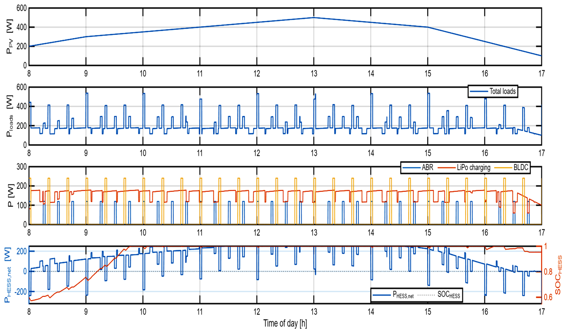
Figure 6 illustrates the temporal variation of the available PV power, which is intentionally modeled as a stepwise signal to emulate realistic irradiance fluctuations. This profile introduces repeated intervals of power surplus and deficit, thereby creating a challenging operating environment for the energy management system. Such variability is representative of real outdoor agricultural scenarios and provides a meaningful basis for evaluating the robustness of the proposed priority-based power allocation strategy.
The net power exchanged by the hybrid energy storage system (HESS) is shown in Figure 6, where positive values indicate charging and negative values correspond to discharging. The results demonstrate that the HESS effectively absorbs excess PV energy during high-generation periods and supplies power during PV shortages. This bidirectional operation confirms the role of the HESS as a dynamic buffer, mitigating power imbalances and ensuring continuity of supply to high-priority loads.
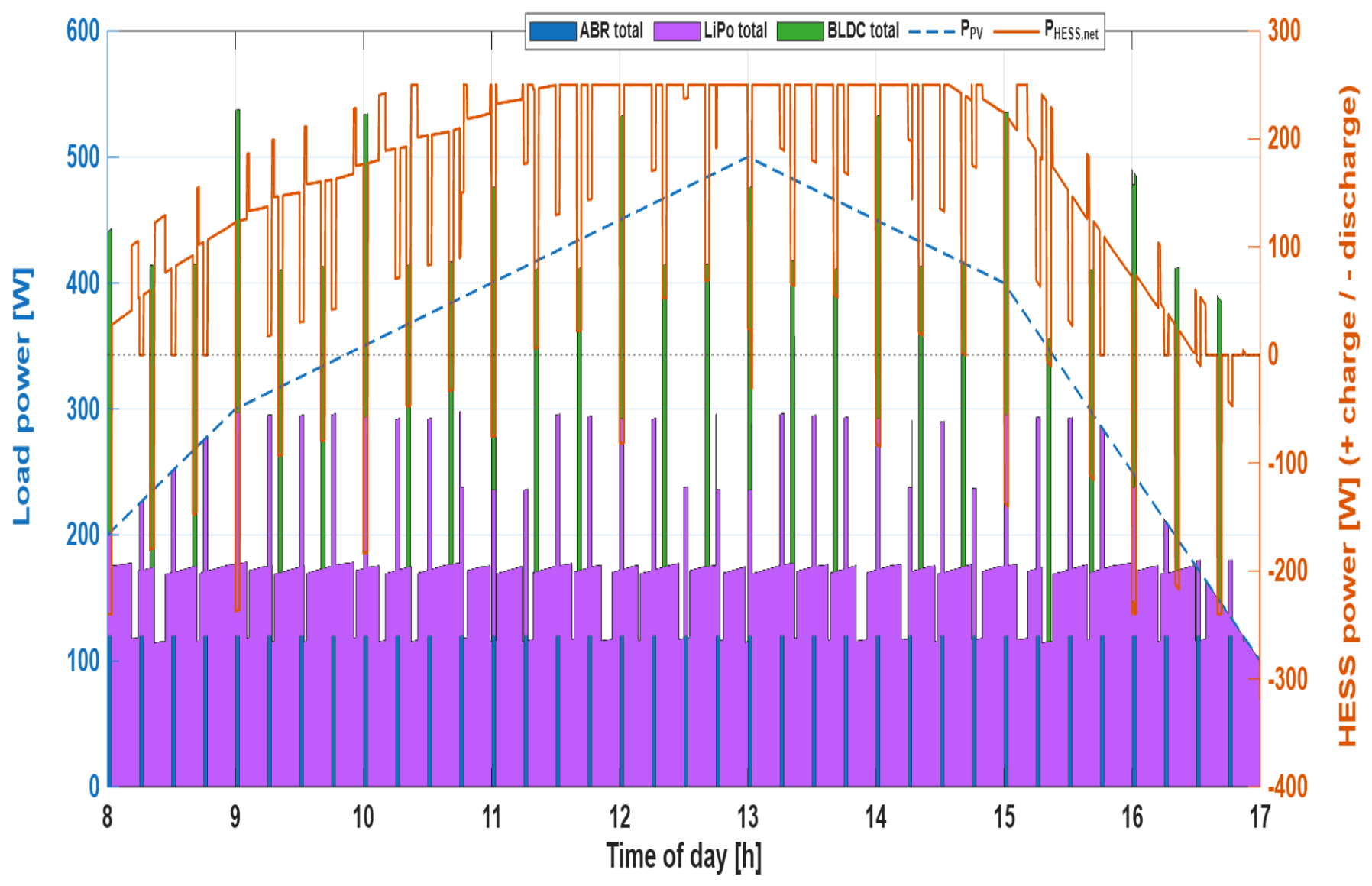
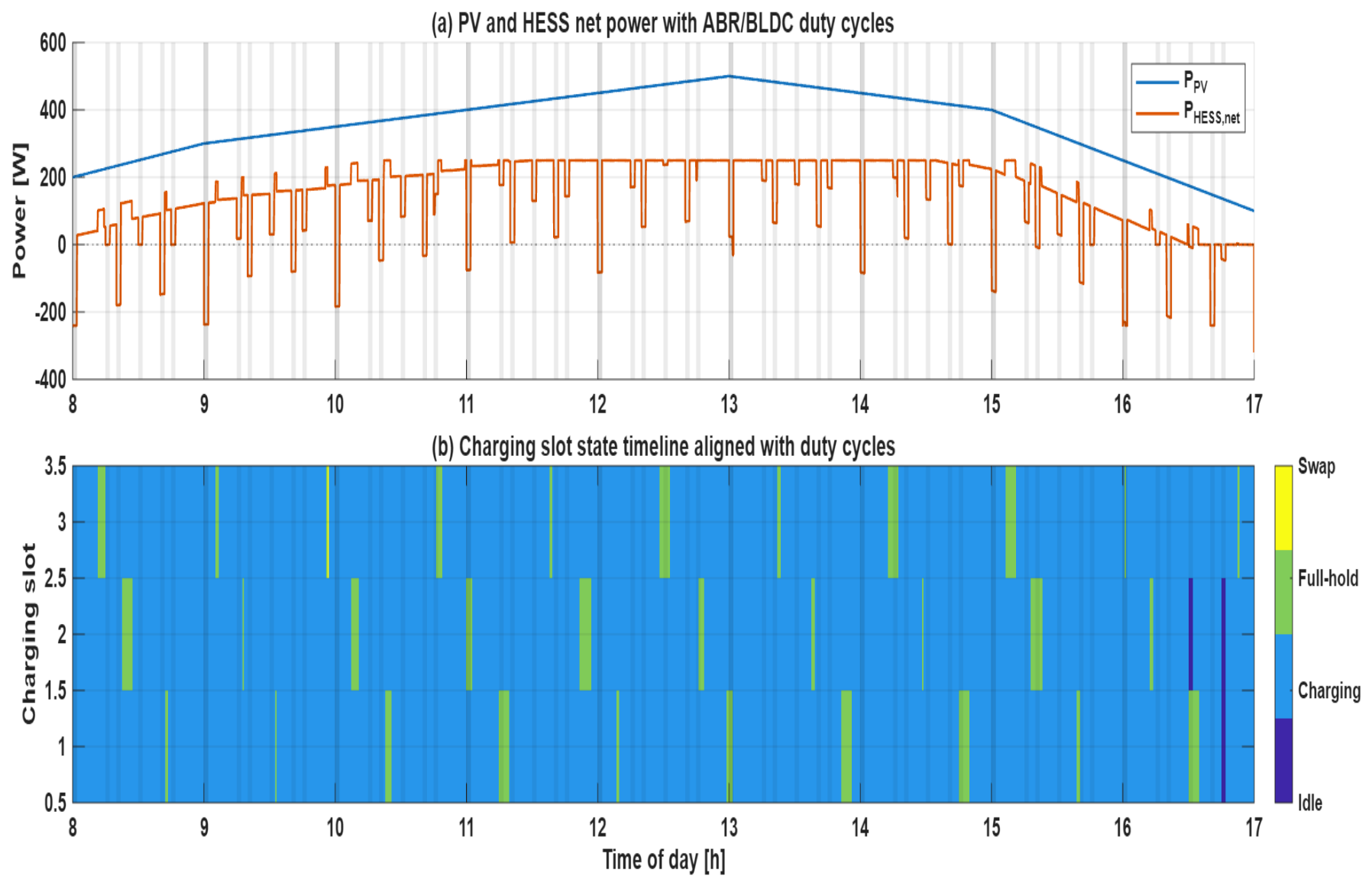
Figure 7 illustrates the interaction between the PV source, HESS, and scheduled ABR and BLDC loads during the daily window of operation. As illustrated in Figure 7a, the available PV power follows a smooth diurnal trend, whereas the net HESS power follows frequent charging–discharging transitions that are driven by the intermittent duty cycles of the ABR stepper motors and BLDC propulsion units. During periods of surplus PV, the HESS is mostly charged while there are brief discharging events to make up for transient power deficiencies caused by load turn-on. Corresponding to this, Figure 7b illustrates the state timeline of charging slots, and it can be observed that battery charging and full-hold and swap events are aligned with the temporal profile imposed by the load duty cycles and renewable variability. The result confirms that the proposed priority-based power management strategy effectively buffers the intermittency of the renewables while providing continuous availability of charging and respecting the operational constraints.
Figure 8 provides a system-level assessment of PV–HESS energy coordination under variable renewable generation and intermittent load demand. While PV output follows a diurnal trend, transient load peaks induce frequent storage intervention. The HESS effectively mitigates short-term power deficits and absorbs surplus energy, maintaining operational stability; however, repeated cycling suggests potential implications for long-term storage aging that warrant further investigation.
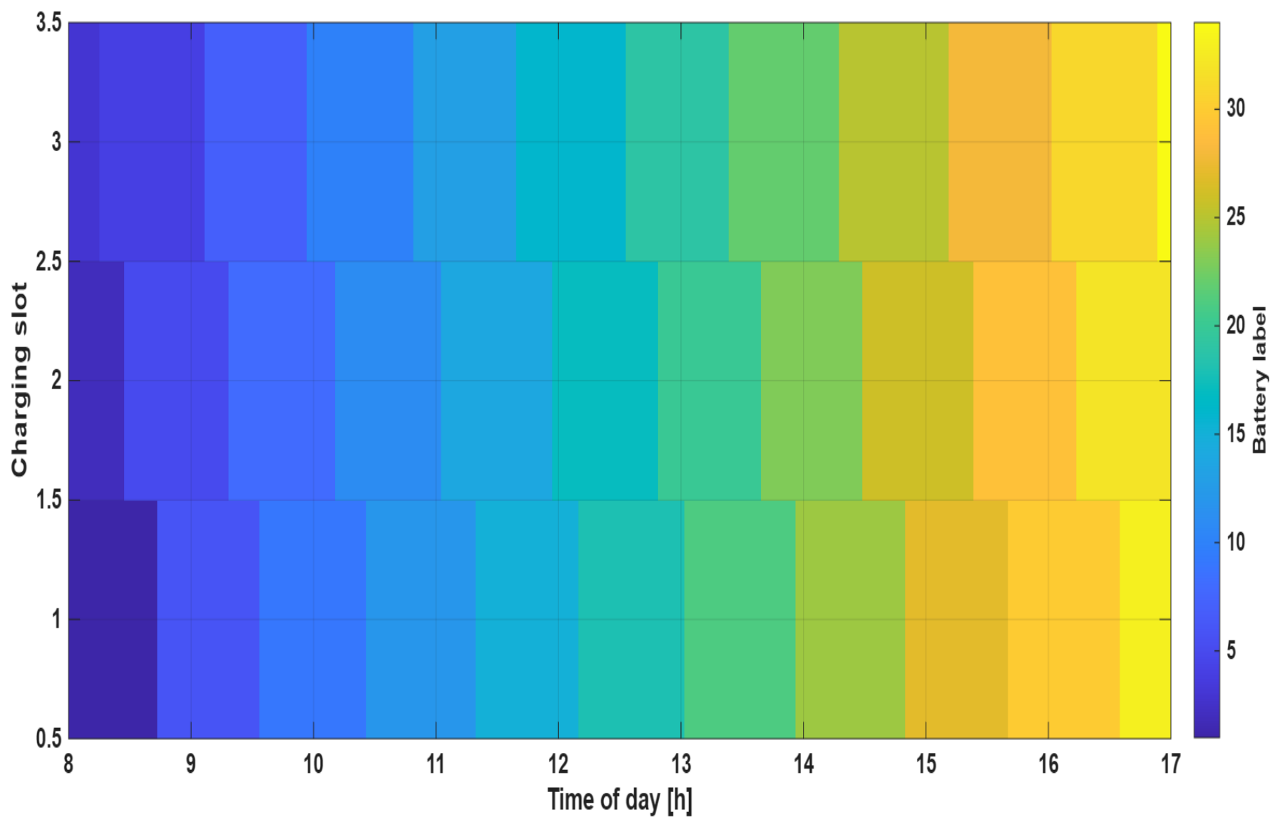
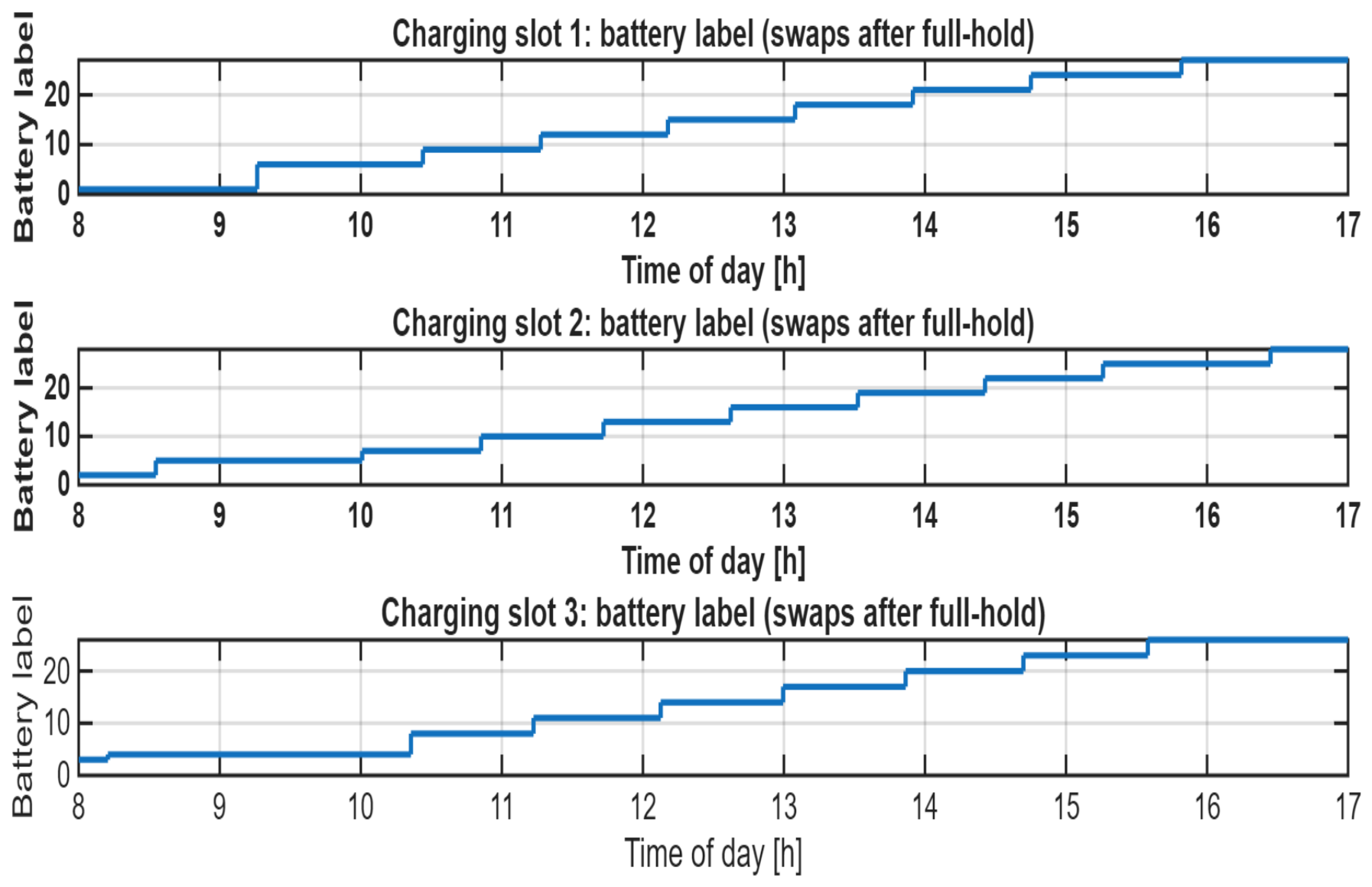
Figure 9 shows the time progression of battery assignments for the battery cells over the charging slots. That is, the continuous step-up in battery labels clearly shows batteries being steadily replaced after they reach the full charge condition. Although the steady step-up of the different slots indicates balanced use of all the batteries, the fast rates of replacement hint at intensive charge/discharge conditions of the batteries.
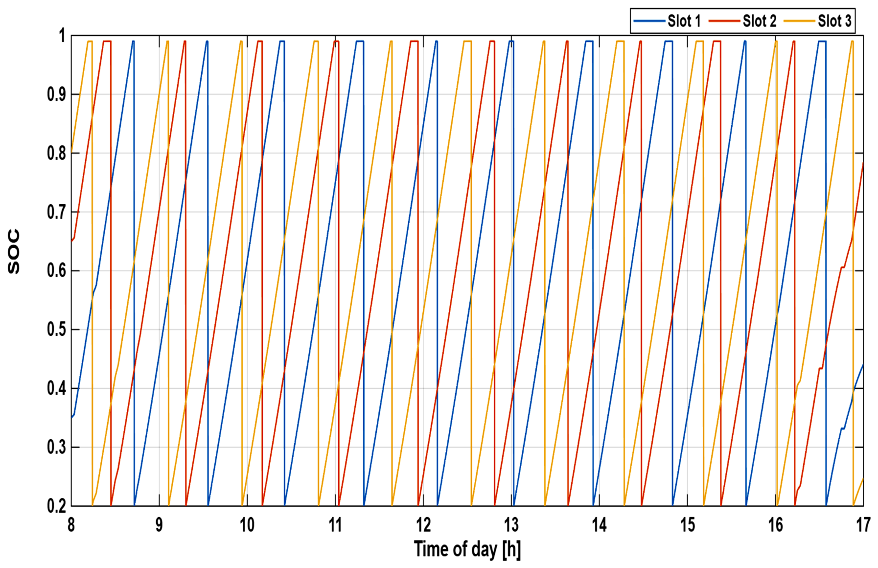
Figure 10 represents the evolution of the state of charge of LiPo batteries for all charging slots during their normal course of operation. These ramp-reset cycles represent consecutive cycles of battery charging and replacement, controlled by the proposed priority-based battery management strategy. Although this ensures a continuous supply of charged batteries, it may cause accelerated degradation of LiPo batteries during normal course of operation due to the frequent high SOC exposure.
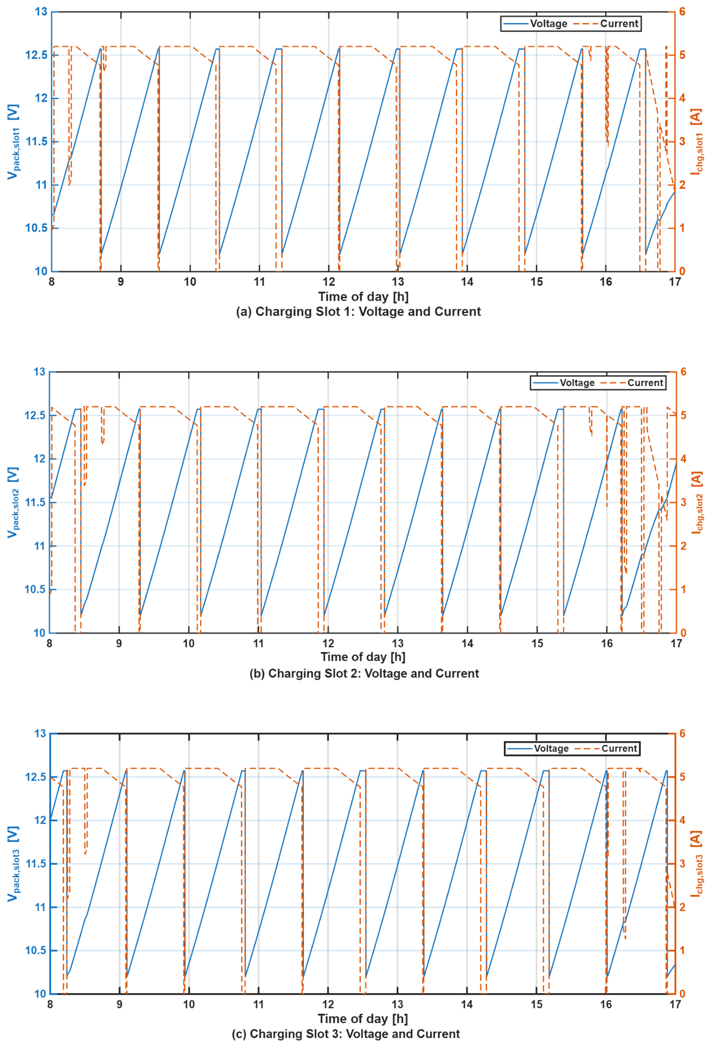
Figure 11 presents an overview of the three LiPo pack daily CC-CV charging profiles for all three slots. The repeating voltage ramping characteristic, followed by current tapering, validates the constant current and constant voltage process. Current oscillations are, again, an indication of power availability with priority scheduling. The voltage has been well maintained within suitable limits. Frequent cycling could result in further stress on the battery.
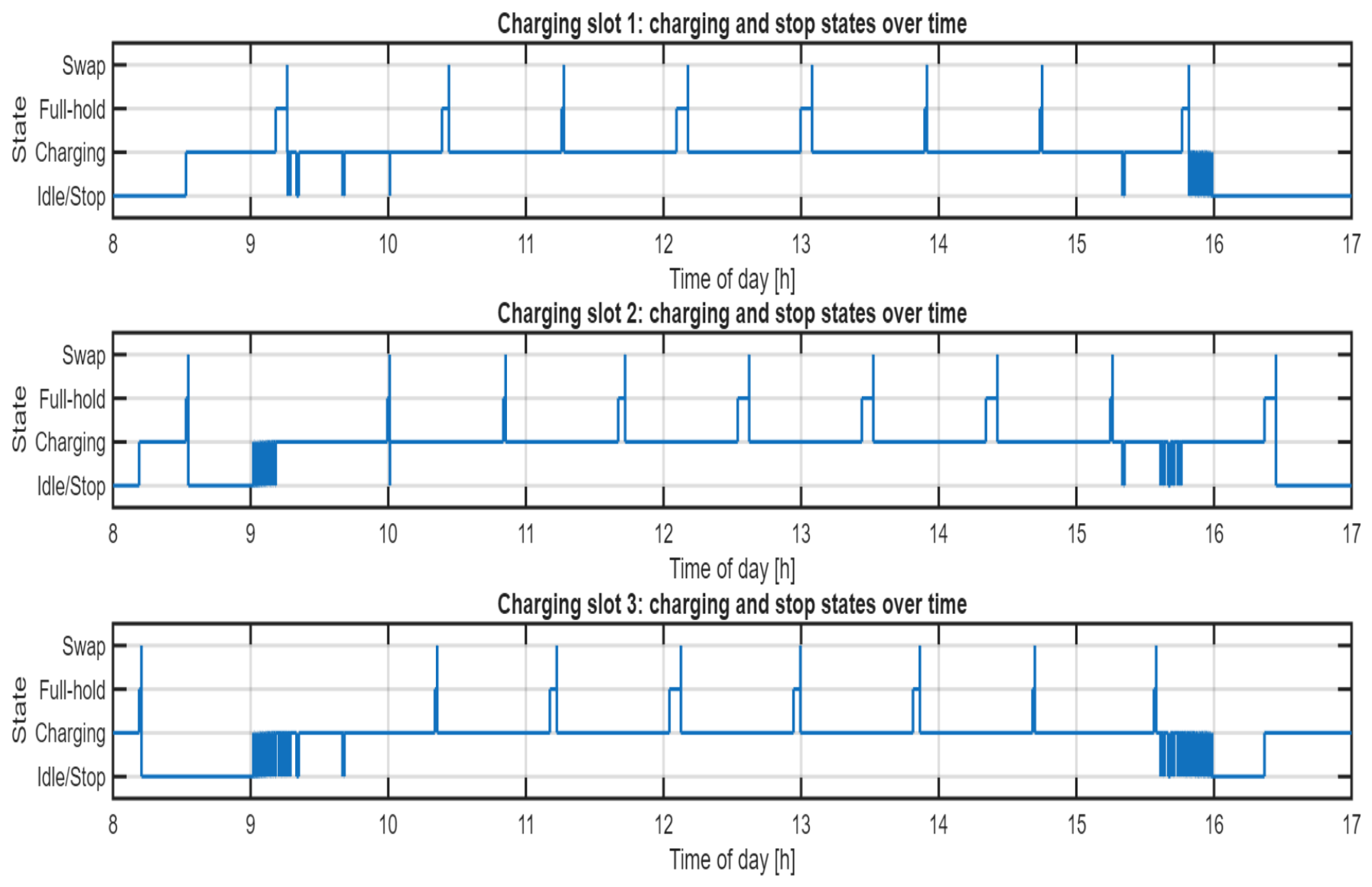
Figure 12 shows the daily operating states of the three LiPo charging slots under the proposed priority-based energy management strategy. Charging periods are mainly aligned with sufficient photovoltaic power availability, while full-hold and swap states indicate successful battery replacement after reaching the target state of charge. Brief charging interruptions observed during early morning and late afternoon are caused by limited PV generation and the activation of higher-priority loads, demonstrating the adaptive power reallocation capability of the supervisory scheduler. Overall, the results confirm stable and coordinated charging–holding–replacement cycles across all slots under time-varying operating conditions.
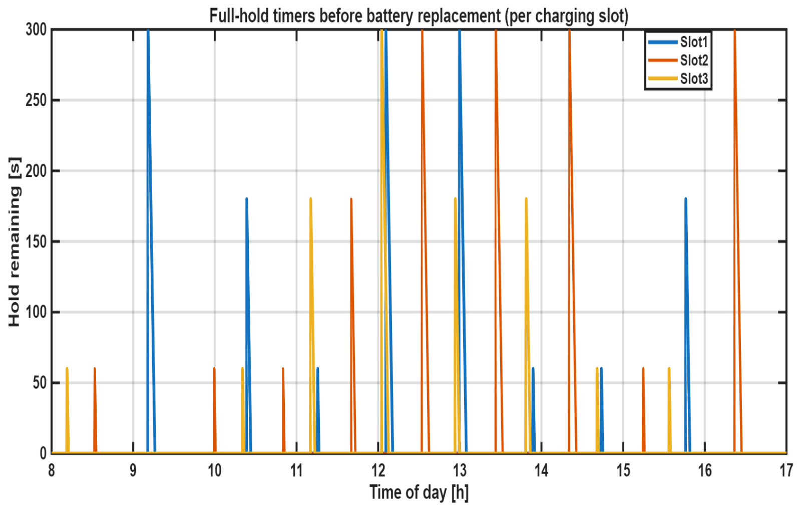
Figure 13 illustrates the evolution of the full-hold timers for the three Li-ion charging slots during the daily operation window. Each spike corresponds to a battery reaching the full state-of-charge, after which a predefined hold duration is applied before physical replacement. The hold times vary between short (60 s) and long (300 s) intervals, reflecting the randomized post-charge dwell strategy implemented in the controller. The asynchronous occurrence of the spikes across the three slots confirms that battery replacement events are decoupled and driven by individual charging completion times rather than synchronized scheduling.
The observed dispersion of hold durations demonstrates the ability of the proposed priority-based energy management system to accommodate stochastic battery handling without disrupting load supply or charging continuity. Longer hold intervals are primarily associated with periods of higher photovoltaic availability, where charging is completed earlier, while shorter holds appear under more constrained power conditions. This behavior reduces simultaneous battery replacement events, mitigating operational congestion and enhancing system robustness under variable renewable generation.
The battery label evolution shown in Figure 14 provides direct insight into the operational continuity of the UAV charging infrastructure. Each incremental label transition represents the successful completion of a charge–hold–swap sequence, indicating that depleted UAV batteries are systematically replenished and replaced without interruption. The asynchronous progression of battery labels across the three charging slots highlights the capability of the proposed power management strategy to support staggered UAV arrivals and departures, thereby avoiding charging bottlenecks and simultaneous battery unavailability. This desynchronization is particularly critical for continuous-mission UAV operations, as it ensures that at least one fully charged battery remains available at any given time, even under fluctuating photovoltaic generation and concurrent mechanical loads. Consequently, the observed swap dynamics confirm that the system can sustain uninterrupted UAV deployment cycles while preserving battery health through controlled full-hold periods and managed replacement timing.
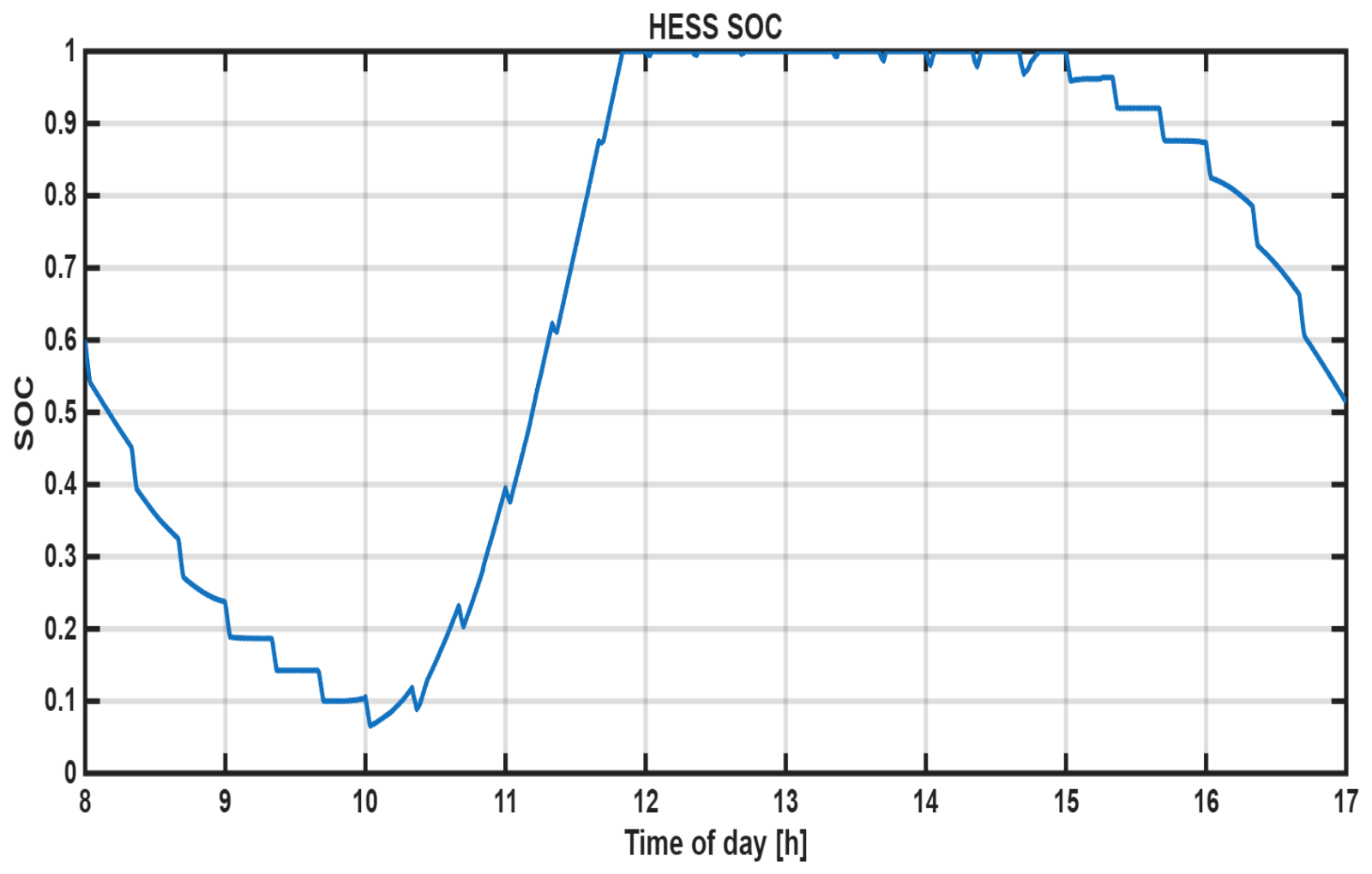
Figure 15 shows that the HESS SOC decreases from approximately 0.55 to 0.08 during the early morning (08:00–10:00) as it compensates for low PV generation while supplying priority loads. With increasing solar availability, the SOC rises sharply between 10:00 and 12:00, reaching near saturation (SOC = 0.98–1.0) and indicating an effective utilization of surplus PV power. During the afternoon period (12:00–17:00), the SOC gradually declines to about 0.52, reflecting controlled discharge to support loads under reduced irradiance, while maintaining sufficient energy reserves for sustained UAV operation.
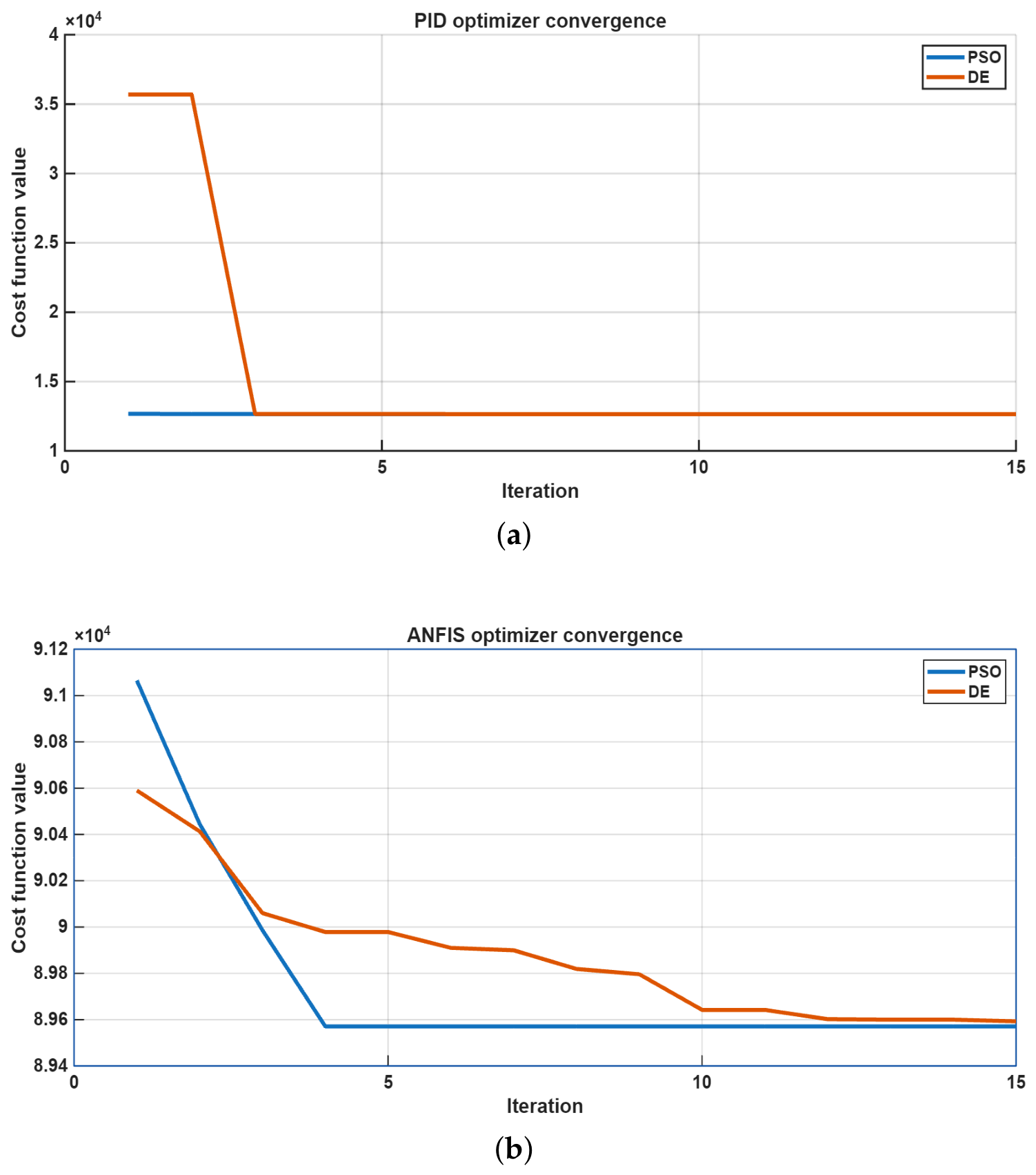
Figure 16 compares the convergence characteristics of the PSO and DE optimization algorithms for PID and ANFIS parameter tuning, respectively. As shown in Figure 16a, both optimizers exhibit stable convergence behavior for PID tuning, with DE achieving a slightly lower final cost-function value than PSO, indicating marginally better optimization performance for PID gain adjustment. In contrast, the ANFIS optimization results in Figure 16b demonstrate that PSO converges more rapidly and reaches a lower final objective value compared with DE, reflecting its stronger capability in handling the nonlinear ANFIS parameter space. These results indicate that the optimization performance depends on the controller structure itself, where DE is more suitable for PID gain tuning, while PSO provides superior convergence and solution quality for ANFIS parameter optimization.
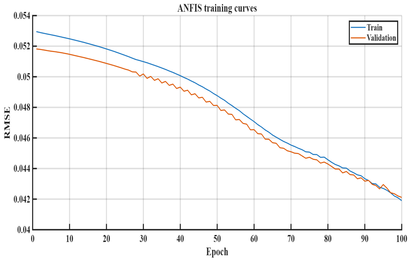
The ANFIS was trained using optimization-derived labels obtained from a constrained thermal cost function, rather than heuristic rules. This allows the learned controller to approximate the optimal temperature-limited current derating policy while remaining computationally efficient for real-time implementation. The resulting training and validation root-mean-square error (RMSE) curves exhibit smooth monotonic convergence without signs of overfitting, as shown in Figure 17. The close agreement between validation labels and ANFIS predictions in Figure 17 confirms accurate approximation of the optimal derating policy.
Battery-lifetime impact is assessed using cumulative degradation proxies, including SOC-weighted thermal dose, high-temperature exposure time, and an aggregated damage index. Results show that the ANFIS-based controller consistently reduces thermal-aging stress compared to the PID controller, despite similar charge throughput, indicating superior long-term battery preservation.
This can be compared with the conventional PID-controlled temperature derating curve; the predictive response for the evolution in the temperature, based on the control surface provided in the ANFIS controller, shows a better adaptation to the variations in the temperature compared to the conventional PID control approach, where the PID controller responds to the variations in the temperature only after they occur, unlike the ANFIS controller, which takes into account the gradients in temperature to adjust the current level accordingly.
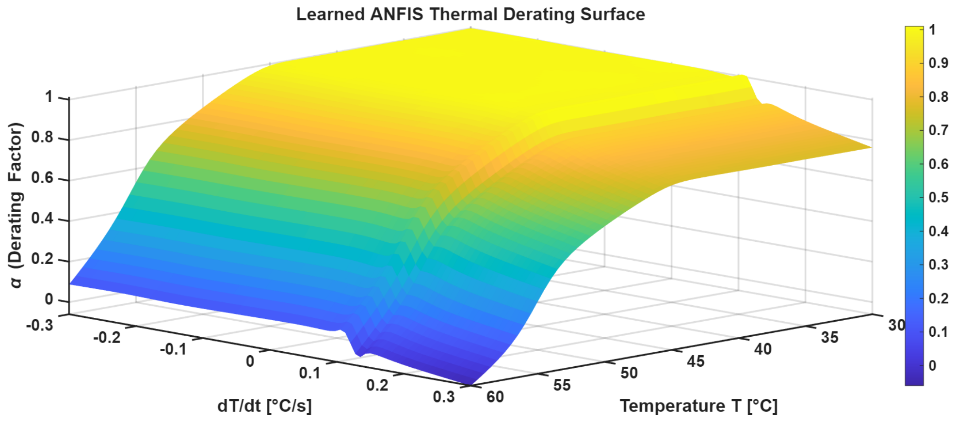
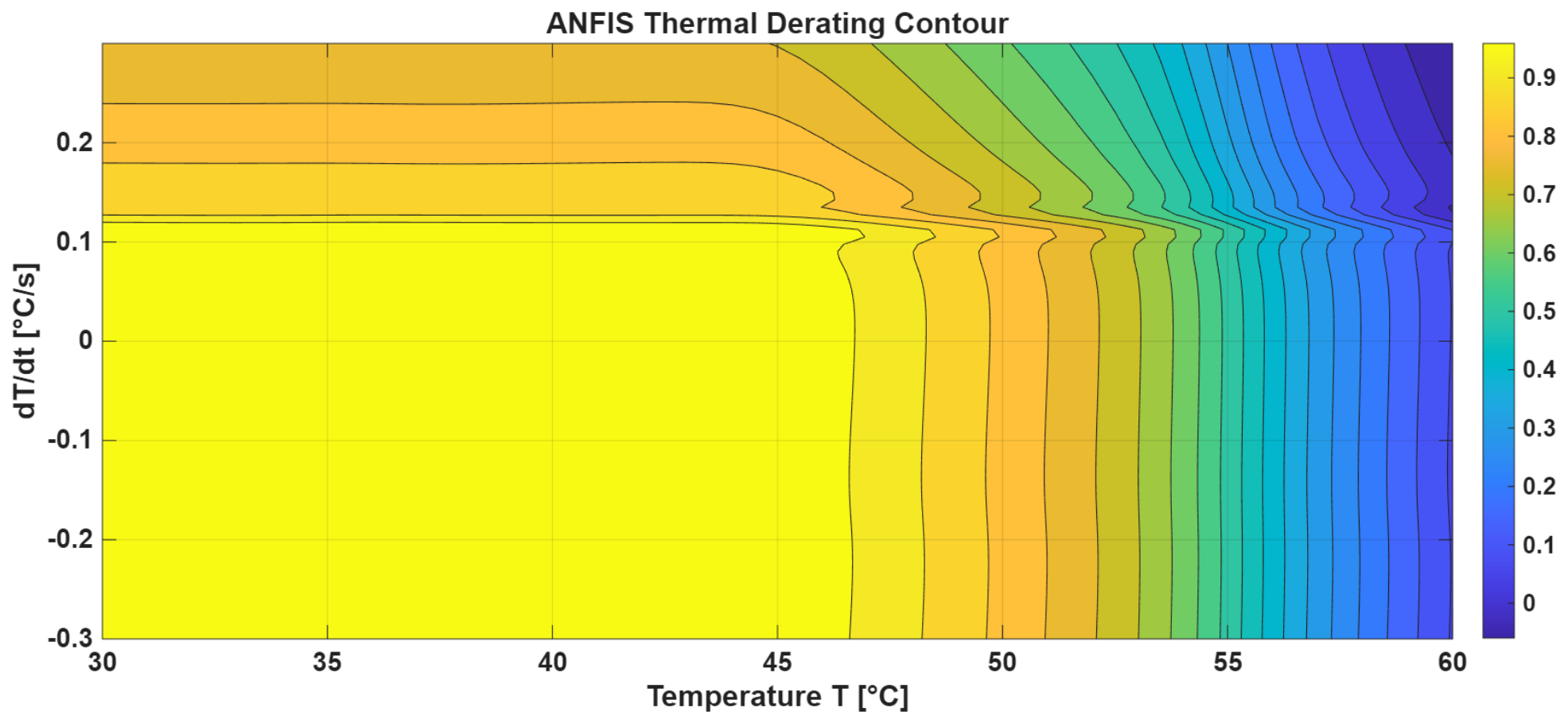
Moreover, the learned ANFIS control surface α ( T , T ˙ ) , plotted in Figure 18, has a physically realistic and smooth nonlinear response with thermal derating characteristics. In contrast to switching approaches, where the derating factor abruptly switches with increasing temperature or thermal gradient, the resulting surface shows smooth continuous variations of the derating factor with the increase in both the battery temperature and the heating rate. In case the temperature is low and the thermal gradient is moderate, the control keeps α 1 , meaning no restrictions on charging are imposed. If the temperature starts approaching the thermal knee point, there is a gradual decline in the α value, which means the ability of the controller to decrease the aggressiveness of charging in order to avoid excessive thermal effects. The influence of the heating rate ( d T / d t > 0 ) grows with increasing temperature; for a positive temperature gradient, the derating process occurs early and aggressively. Such thermal behavior is preferable when it comes to lithium-ion charging since it helps avoid the accumulation of high temperatures before the critical points have been reached. The surface shows no discontinuities or oscillations, meaning that its control behavior is stable; the ANFIS has successfully learned nonlinear electrothermal interactions. The contours presented in Figure 19 also reveal additional insights on the thermal-aware decision boundaries learned by the ANFIS controller. It is clear from the figure that the controller has learned three different operating zones based on the two inputs. In the first region (safe thermal region, around 30–45 °C, high values of α are retained to allow for efficient charging while ensuring minimal current limitation. In the second zone (around 30–45 °C), the derating parameter gradually falls to accommodate current limitations aimed at safe electrothermal charging. Further, in cases where the battery temperatures exceed the intermediate operating zone (especially in cases where there are positive thermal gradient conditions), the controller learns a steep reduction in the values of α . This means that the decision boundary is smooth with no sharp discontinuities. Such behavior is expected since it eliminates the possibility of current oscillations and ensures that the battery does not undergo thermal overshoots. The interdependence of temperature and rate-of-heating effects implies that the developed controller depends on more than just temperature factors.

Sensitivity Analysis of Lifetime Indicators

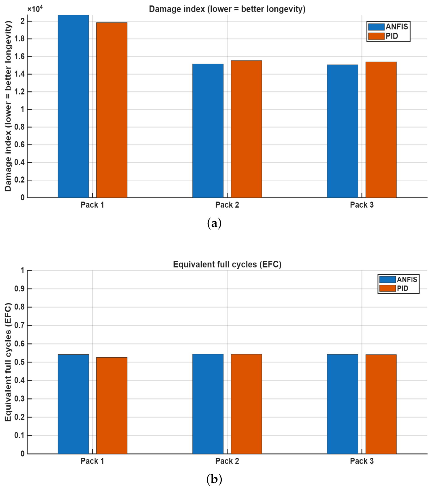
Figure 20 compares the lifetime-related degradation indicators obtained using the ANFIS and PID temperature-limited charging strategies. As illustrated in Figure 20a, the SOC-weighted thermal dose associated with the ANFIS controller remains consistently lower than that of the PID controller for Packs 2 and 3, indicating reduced cumulative thermal stress during charging. While Pack 1 exhibits a slightly higher thermal dose under the ANFIS strategy, the overall trend across the battery packs demonstrates that the ANFIS-based thermal-aware charging approach more effectively suppresses excessive heat exposure, particularly under higher charging-demand conditions. For Packs 2 and 3, the PID controller reaches thermal-dose values close to 1.7 × 10 4 s · weight , whereas the ANFIS controller limits the accumulated thermal dose to approximately 1.1 × 10 4 s · weight , corresponding to a noticeable reduction in thermal-aging stress.
The equivalent full cycles (EFC) results shown in Figure 20b further confirm the superiority of the ANFIS-based charging strategy in mitigating battery degradation. The ANFIS controller maintains significantly lower EFC values for all battery packs compared with the PID controller, indicating reduced effective charge throughput and lower degradation accumulation during operation. Specifically, the PID controller reaches EFC values of approximately 0.35 for Pack 1 and nearly 0.50 for Packs 2 and 3, whereas the ANFIS controller limits the EFC values to below 0.05 for all packs. This substantial reduction demonstrates that the ANFIS-based thermal-aware controller effectively moderates aggressive charging actions and minimizes electrothermal stress, thereby contributing to improved long-term battery lifetime and safer charging operation.
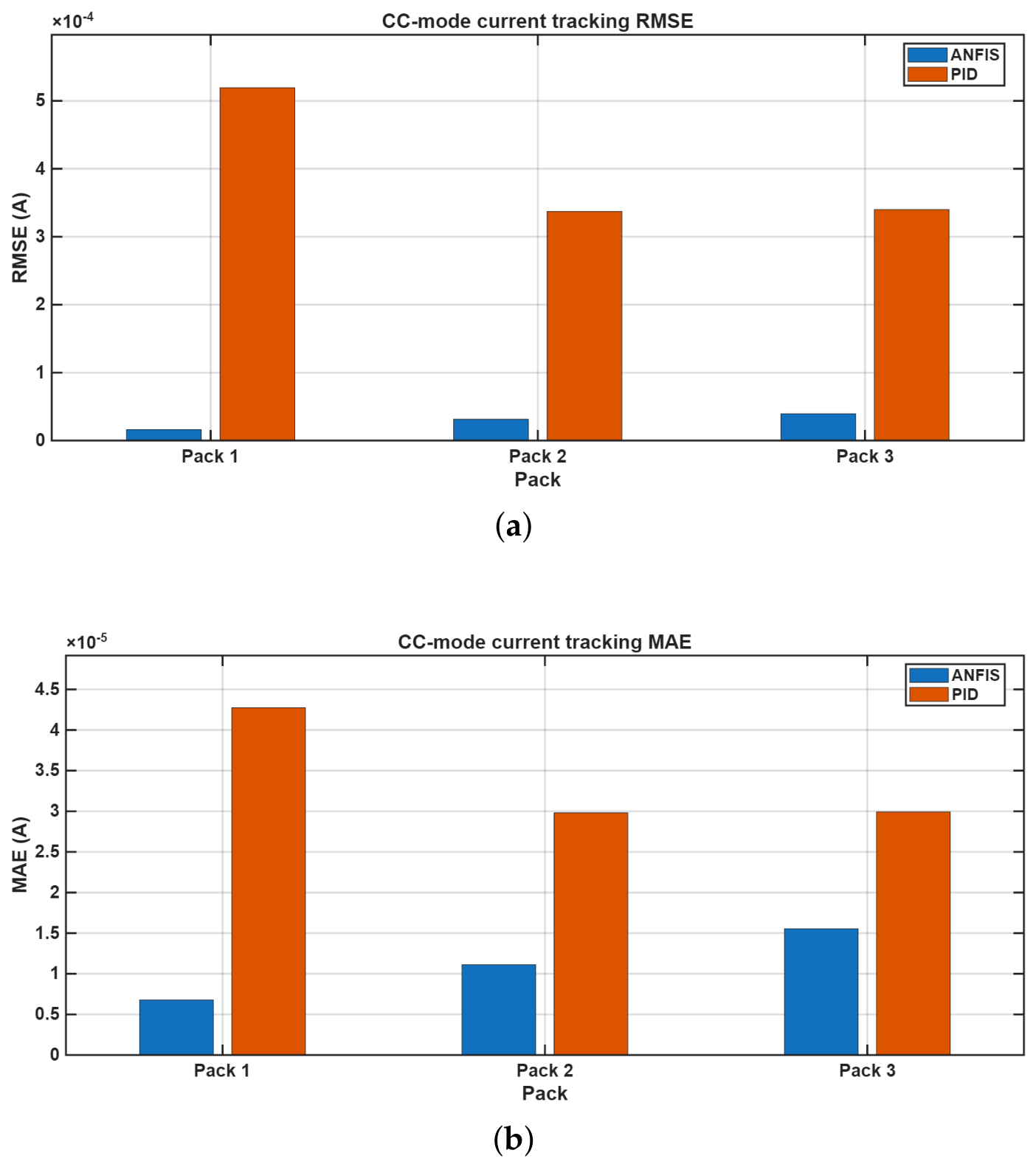
Figure 21 compares the CC-mode current-tracking performance of the ANFIS and PID controllers in terms of RMSE and MAE for the three battery packs. As illustrated in Figure 21a, the ANFIS controller achieves substantially lower RMSE values compared with the PID controller across all packs, confirming superior current-reference tracking accuracy and smoother dynamic behavior. For Pack 1, the RMSE obtained using the ANFIS controller is 1.63 × 10 5 A, whereas the PID controller exhibits an RMSE of 5.19 × 10 4 A, corresponding to a reduction exceeding 96.9%. Similarly, for Packs 2 and 3, the PID controller yields RMSE values of 3.37 × 10 4 A and 3.40 × 10 4 A, respectively, while the ANFIS controller maintains errors of 3.13 × 10 5 A and 3.95 × 10 5 A, representing reductions of approximately 90.7% and 88.4%. These results confirm that the ANFIS-based thermal-aware current regulation significantly improves the stability and precision of CC-mode charging compared with the conventional PID approach.
The MAE results presented in Figure 21b reinforce the same trend observed for RMSE. The ANFIS controller consistently achieves extremely small average absolute tracking errors across all packs, remaining close to the zero-error region. For Pack 1, the PID controller records an MAE of 4.28 × 10 5 A, whereas the ANFIS controller maintains a near-negligible error of 6.78 × 10 6 A, a reduction of approximately 84.2%. Comparable improvements are observed for Packs 2 and 3, where the PID controller produces MAE values of 2.98 × 10 5 A and 2.99 × 10 5 A, while the ANFIS controller preserves consistently minimal deviations of 1.11 × 10 5 A and 1.55 × 10 5 A, corresponding to reductions of 62.8% and 48.2%, respectively. Overall, these results demonstrate that the ANFIS controller provides more accurate and robust CC-mode current regulation, with reduced oscillations and improved reference-following capability under thermally constrained charging conditions.
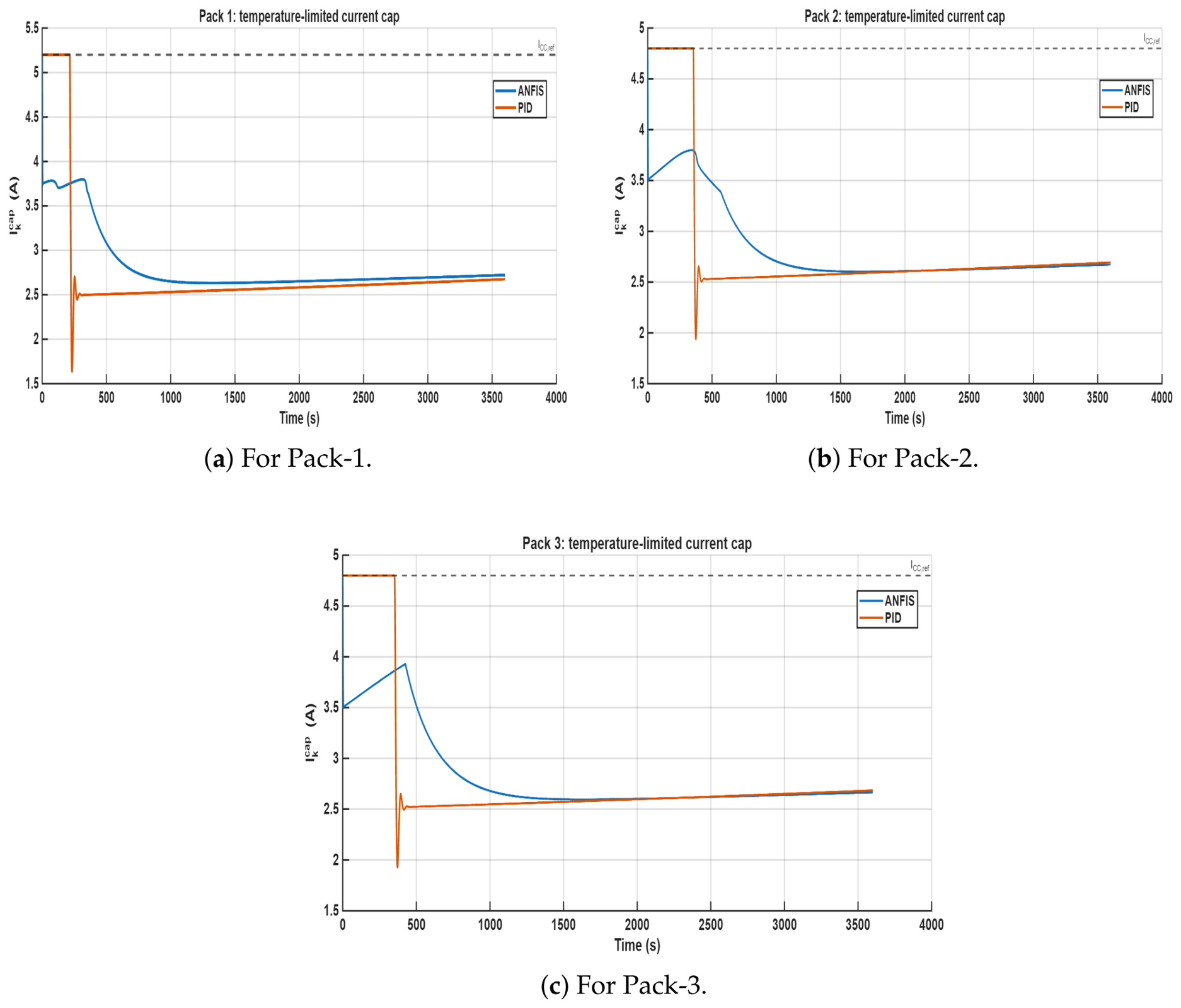
Figure 22 illustrates a comparison revealing fundamental differences in how the two controllers manage electrothermal constraints during the charging process. The PID controller maintains relatively high charging currents until an almost critical condition is reached, leading to an abrupt shutdown at approximately 1200 s. In contrast, the ANFIS controller initiates current derating earlier (around 500 s), prior to reaching the electrothermal limit. This anticipatory behavior helps avoid sharp transitions and temperature gradients that may induce electrochemical stress. Moreover, the ANFIS controller sustains charging for a longer duration before shutdown (approximately 2900 s) compared with the PID controller, indicating more effective utilization of the safe thermal operating region. Such characteristics are particularly advantageous for lithium-ion cells, where nonlinear thermal effects and temperature-induced aging play a significant role in performance degradation.
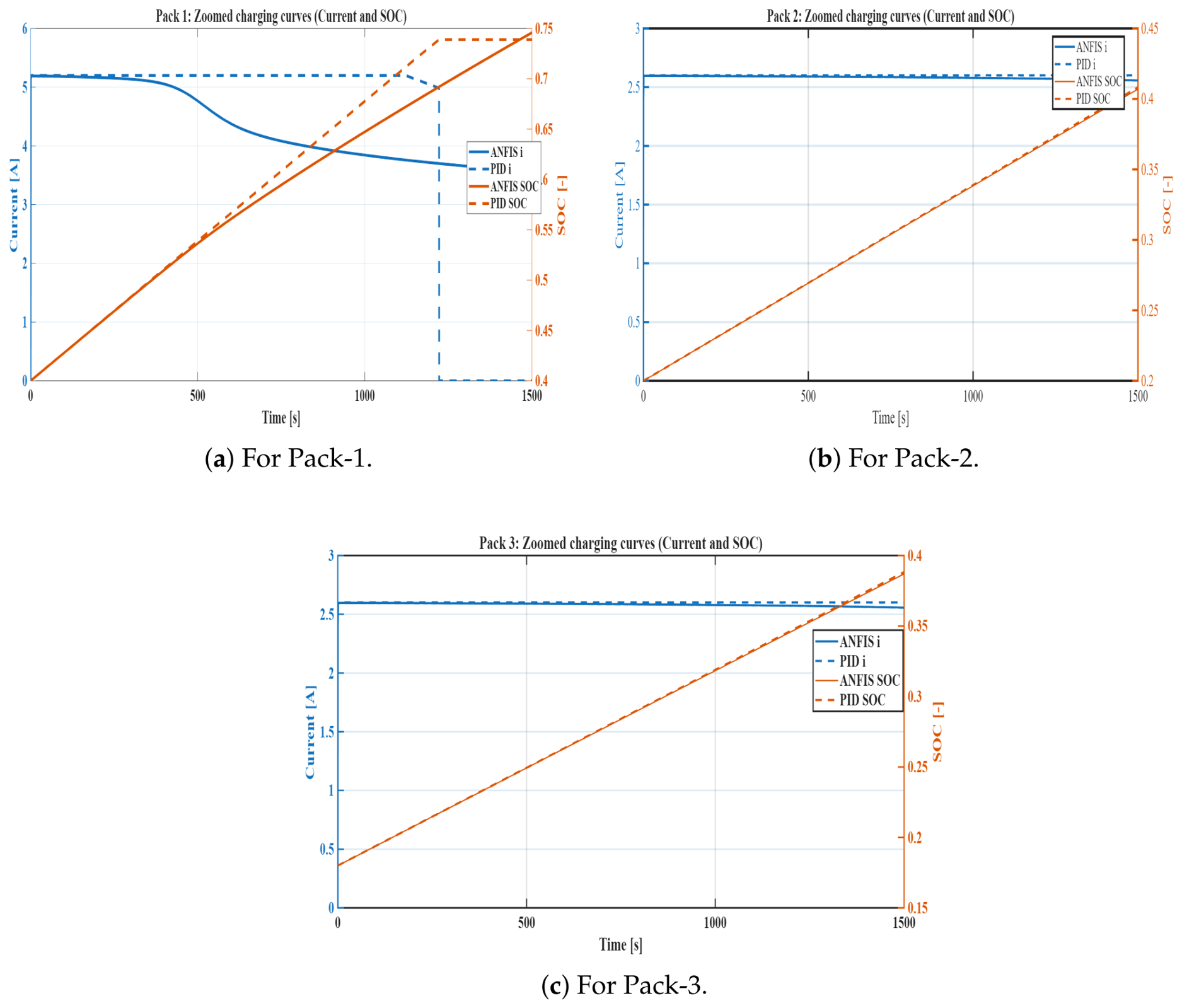
The zoomed charging curves in Figure 23 demonstrate significant differences between the ANFIS-based and PID controllers across the three packs. For Pack 1, the ANFIS controller gradually derates the current from approximately 5.2 A after about 500 s, resulting in a smooth SOC evolution. In contrast, the PID controller maintains an almost constant current of about 5.2 A until roughly 1200 s, followed by an abrupt current drop, indicating a more aggressive derating strategy. For Packs 2 and 3, both controllers exhibit similar current levels (around 2.6 A) and nearly identical SOC evolution, suggesting that thermal or operational constraints are less restrictive in these packs.
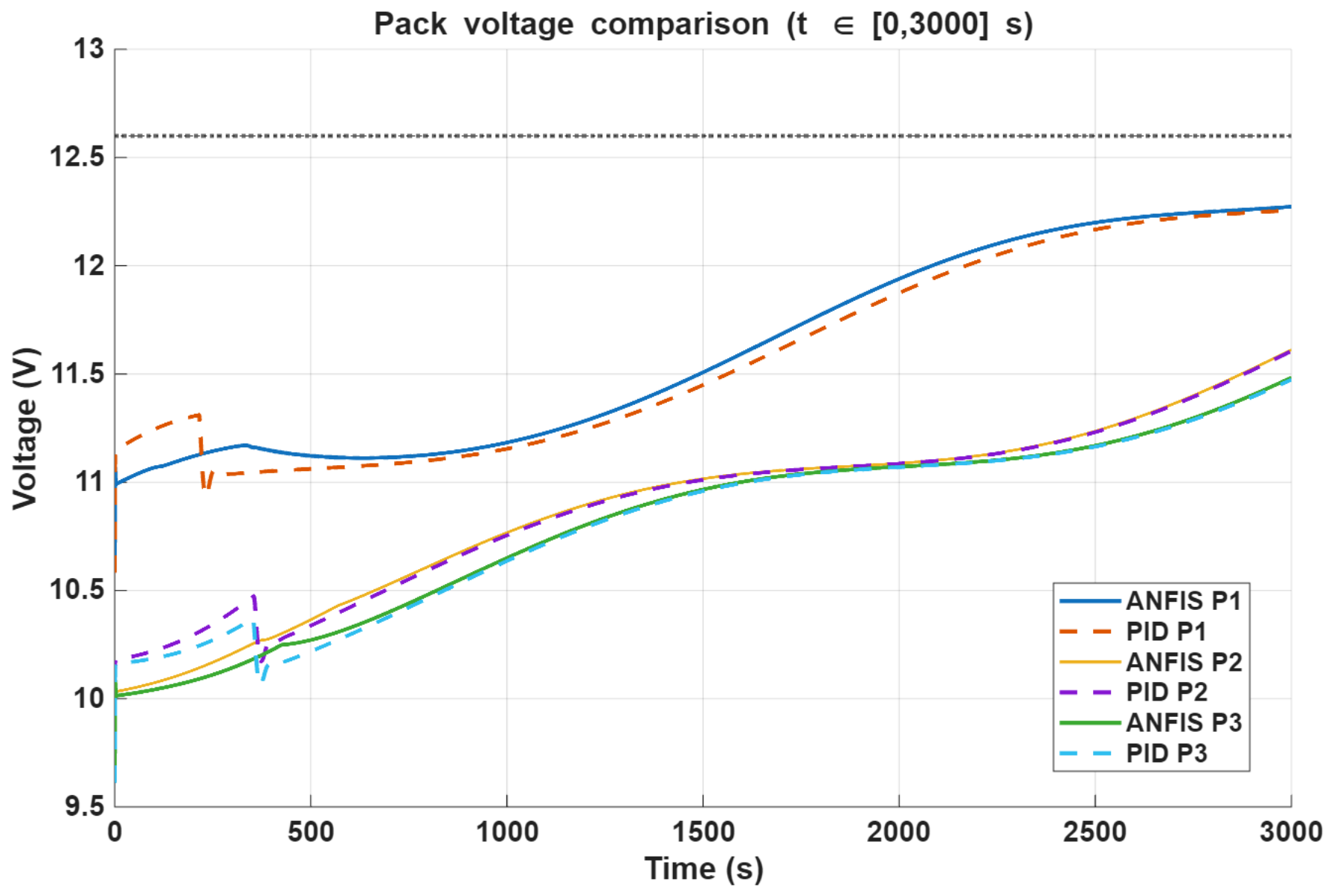
Figure 24 illustrates the pack voltage evolution for both controllers over the interval t [ 0 , 3000 ] s, with the dotted horizontal line marking the maximum permissible pack voltage of V max = 12.6 V. The three packs exhibit distinct initial voltage levels consistent with their respective initial SOC values: Pack 1 begins at approximately 11.0 V ( SOC 0 = 0.40 ), while Packs 2 and 3 start near 10.0 V ( SOC 0 = 0.20 and 0.18 , respectively). Across all packs, both controllers maintain voltages strictly below V max throughout the entire simulation window, confirming that the CC-mode current references issued by the temperature limiter never drive the pack beyond its electrochemical safety boundary.
A notable early transient is observed for Pack 1 between t 300 s and t 500 s, where both ANFIS and PID momentarily reduce the charging current in response to the rising pack temperature approaching T knee , producing a brief plateau and slight voltage dip before current is gradually restored. After this thermal derating phase, the ANFIS controller sustains a consistently higher voltage trajectory for Pack 1, reaching approximately 12.3 V at t = 3000 s compared with 12.25 V under PID, reflecting the higher cumulative charge delivered by the ANFIS-regulated current profile. For Packs 2 and 3, the voltage traces of both controllers remain closely overlapping throughout the simulation, which is consistent with the comparable charge throughput and SOC evolution reported in Table 5 for these packs. Overall, the voltage profiles confirm that both controllers successfully respect the upper voltage constraint, while the ANFIS controller achieves a marginally faster voltage rise on the thermally more stressed Pack 1, further validating its superior charging performance under multi-pack thermal constraints.
In general, this comparative study tends to show that the temperature-aware charging approach with ANFIS ensures a smoother derating of currents, higher tracking accuracy, and better thermal utilization than the classic PID controller. Specifically, ANFIS results in a smoother activation of the thermal constraint, stable current regulation under CC operation, lower values of error RMSE/MAE (especially for Pack 1), and lower lifetime damage proxy. These results suggest that data-driven nonlinear control can better capture electrothermal battery dynamics than classical linear PID schemes, which implies better stability during charging, lower thermal stress, and potentially improved longevity for batteries. The simulation results illustrate the dynamic behavior of the proposed priority-based power management strategy for a photovoltaic (PV)–powered system integrated with a hybrid energy storage system (HESS) supplying multiple heterogeneous loads. The presented curves capture the temporal variations of available PV power, load power allocation, HESS power exchange and state of charge (SOC), as well as the charging dynamics of multiple LiPo battery packs. These results collectively demonstrate how the system responds to fluctuating renewable generation, scheduled and unscheduled load demands, and operational constraints imposed by charging limits and battery management logic.
Specifically, the plots show coordinated power sharing among high-priority ABR stepper motors, LiPo battery charging tasks, and BLDC propulsion motors, while maintaining energy balance through controlled HESS charging and discharging. The SOC trajectories of both the HESS and LiPo packs reflect the effectiveness of the energy buffering and scheduling mechanisms, including max-first LiPo selection, urgent charging activation, and battery replacement after full-charge holding periods. Additional timelines visualize priority enforcement, charging states, and battery swapping events, providing insight into the temporal decision-making of the controller. Together, these curves establish a comprehensive picture of system-level performance and form the basis for the detailed analysis discussed in the following subsections.
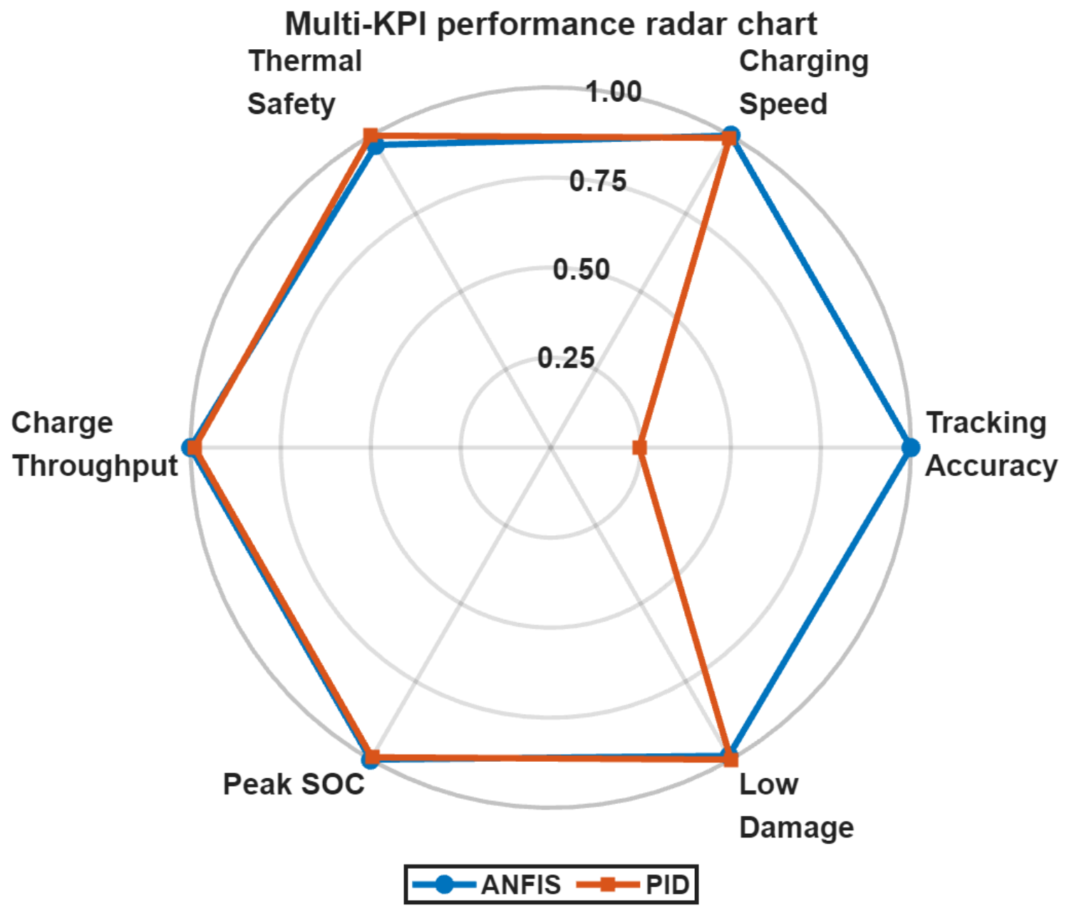
Figure 25 presents a normalized multi-KPI radar chart that provides a holistic comparison of the ANFIS and PID controllers across six performance dimensions: charging speed, tracking accuracy, low damage index, peak SOC, charge throughput, and thermal safety. Each axis is normalized to the interval [ 0 , 1 ] , where a value of 1.0 represents the best achievable performance for that metric. The most prominent distinction between the two controllers is observed along the tracking accuracy axis, where the ANFIS controller reaches a near-unity score while the PID controller scores approximately 0.10, reflecting the 32 × reduction in RMSE demonstrated quantitatively in Table 5. Along the remaining five axes, both controllers exhibit comparable performance, with only marginal differences. The ANFIS controller maintains a slightly larger enclosed area for charging speed, charge throughput, and peak SOC, confirming its ability to deliver more charge within the same simulation horizon. Conversely, the PID controller scores marginally higher on the thermal safety and low damage axes, consistent with its slightly lower peak temperatures and mean damage index reported in Table 5. Importantly, the overall polygon area enclosed by the ANFIS profile is substantially larger than that of the PID profile, driven predominantly by the tracking accuracy advantage, which indicates that the ANFIS controller achieves a superior aggregate performance across the full set of KPIs considered. These results collectively confirm that the proposed ANFIS-based controller represents a well-rounded and practically deployable solution for multi-pack fast-charging management, combining high current-tracking precision with competitive thermal and longevity characteristics.
The quantitative results presented in Table 5 demonstrate that the proposed ANFIS controller, optimized by PSO, consistently outperforms the PID controller, optimized by DE, across the majority of performance metrics. In terms of CC-mode current tracking accuracy, the ANFIS controller achieves RMSE values of 1.63 × 10 5 , 3.13 × 10 5 , and 3.95 × 10 5 A for Packs 1–3, respectively, representing improvements of approximately 32 × , 11 × , and 9 × over the corresponding PID values of 5.19 × 10 4 , 3.37 × 10 4 , and 3.40 × 10 4 A. A consistent reduction in MAE further corroborates the superior reference-tracking precision of the ANFIS controller across all three packs. From a charging performance perspective, ANFIS delivers higher charge throughput (2.818 Ah vs. 2.737 Ah for Pack 1), higher equivalent full cycles (0.542 vs. 0.526), and a greater peak SOC (0.942 vs. 0.926), confirming faster and more complete charging under identical power constraints. Notably, the peak C-rate under ANFIS (0.861) is considerably lower than that of PID (1.000), indicating a smoother current profile that reduces instantaneous cell stress. Regarding thermal behavior, both controllers successfully prevent the pack temperature from approaching T max , with zero time recorded near this limit for all packs. Although the PID controller exhibits marginally lower peak temperatures (45.98 °C vs. 46.43 °C for Pack 1), the ANFIS controller spends significantly less time above 50 °C (3263.5 s vs. 3441.0 s for Pack 1), suggesting more effective thermal regulation in the critical high-temperature region. In terms of battery longevity, the SOC-weighted thermal dose and damage index are slightly higher for ANFIS on Pack 1 (20,694 vs. 19,844), attributable to the longer time spent at elevated SOC during faster charging; however, the mean damage index across all three packs differs by only 0.6 % ( 1.70 × 10 4 vs. 1.69 × 10 4 ), a negligible margin compared with the substantial tracking and charging gains. Taken together, these results establish that the ANFIS controller achieves a superior balance between charging speed, current tracking precision, and thermal safety, making it the preferred candidate for deployment in multi-pack fast-charging stations.
Collectively, the simulation results demonstrate that the proposed priority-based energy management framework successfully addresses the core operational challenges of renewable-powered UAV ground-support stations. The strict lexicographic priority enforcement ensures that mission-critical actions—battery replacement actuation and LiPo pack charging—are never interrupted by lower-priority loads or by fluctuations in solar irradiance, with the HESS providing seamless compensation during PV deficit intervals. The physically consistent bidirectional HESS power behavior, with net positive power during surplus absorption and net negative power during deficit compensation, confirms that the proposed supervisory logic correctly coordinates energy storage without sign conflicts or chattering, a property directly relevant to the long-term reliability of the storage hardware in field-deployed stations. Furthermore, the ANFIS-based thermal derating controller consistently reduces cumulative battery degradation proxies—including SOC-weighted thermal dose and equivalent full cycles—compared with the PID baseline, indicating that the proposed architecture not only maintains operational continuity but also extends the serviceable lifetime of the LiPo packs in the charging inventory. Taken together, these outcomes establish that the proposed framework provides a scalable and practically deployable solution for renewable-powered UAV infrastructure, where guaranteeing mission continuity, energy efficiency, and battery longevity under time-varying solar generation are simultaneously critical requirements.

6. Conclusions

This paper presented an integrated charging and energy-management framework for a PV-powered movable UAV charging station supplying heterogeneous loads while simultaneously charging multiple LiPo packs. A supervisory priority-based allocator was developed to enforce mission requirements under variable PV generation and limited storage resources. The allocator guarantees operation of the ABR stepper motors according to their duty cycle as the highest-priority task, then allocates the remaining power to LiPo charging (including an event-driven urgent mode), followed by intermittent BLDC actuation, and finally charges the HESS when surplus PV power is available. A CC–CV charging strategy augmented with ANFIS-based current regulation was incorporated to provide smooth nonlinear current derating under operating constraints, thereby improving charging safety and avoiding abrupt current changes. To emulate continuous operation, a slot-based battery swapping mechanism was added, where fully charged packs are held for a randomized dwell time and then replaced by depleted packs with sequential labels, enabling repeated charge–swap cycles over the simulation horizon.
Simulation results showed that the proposed approach (i) maintains strict priority compliance for critical actions even during PV power shortages by utilizing HESS discharge, (ii) achieves coherent signed HESS power behavior (positive during charging and negative during discharging), (iii) produces bounded and smooth charging-current and voltage trajectories through ANFIS regulation, and (iv) supports continuous mission logistics by repeatedly preparing and swapping LiPo packs while tracking slot states and replacement events. These outcomes indicate that the proposed architecture can improve renewable-power utilization and operational reliability for UAV ground-support stations.
Unlike conventional PID controllers that react solely to temperature deviations, the trained ANFIS embeds predictive thermal awareness by jointly considering temperature magnitude and rise rate. This enables earlier and smoother derating actions, reducing thermal stress without sacrificing charging speed. As demonstrated in the subsequent simulation results, the ANFIS-assisted controller outperforms PID regulation in terms of peak temperature reduction, time spent above critical thresholds, and current tracking smoothness, thereby contributing to enhanced battery safety and extended lifetime in power-constrained UAV charging stations.
Although both controllers achieve effective charging, the ANFIS strategy significantly reduces cumulative thermal and SOC-related aging stress, indicating superior long-term battery lifetime preservation compared to PID control.

7. Challenges and Future Work

7.1. Limitations of the Work

Since the proposed scheme relies heavily on an ANFIS model built and fine-tuned offline, the quality of the input data fed into the controller plays an important role in terms of ensuring its performance. Therefore, in the case when the operation takes place in an environment where conditions differ drastically from the ones encountered during training (for instance, extremely high/low temperatures and aged batteries), retraining of the controller or its adjustment might become necessary.
Furthermore, this scheme imposes higher computational complexity than traditional CC–CV schemes. Specifically, this is due to the use of the ANFIS algorithm along with a supervisory strategy for allocating power consumption to each phase of the charging process. Third, the effectiveness of this approach depends on the reliability of the measurements of variables such as battery temperature, SOC, and available PV power.
Fourth, the current validation is primarily based on simulation results. Although the hardware platform has been developed, full experimental validation of the proposed control strategy is still ongoing. Therefore, real-world uncertainties such as converter non-idealities, communication delays, and environmental disturbances are not yet fully captured.
Finally, the priority-based power allocation strategy, while effective in ensuring mission-critical operation, may lead to temporary underutilization of available energy for lower-priority loads. This trade-off is inherent to the strict prioritization policy and may require further refinement for applications with different operational objectives.
Future work will address these limitations by incorporating online learning mechanisms for ANFIS adaptation, enhancing robustness against measurement uncertainties, and performing comprehensive experimental validation under real operating conditions. Despite the encouraging results obtained with the proposed scheme, several shortcomings remain.

7.2. Future Work

Future work will focus on incorporating a higher-fidelity LiPo electro-thermal model and aging-aware constraints, extending the allocator to explicitly optimize charging completion time and HESS cycling cost, and validating the proposed strategy experimentally on a hardware testbed including PV emulation, bidirectional HESS converters, and a real ABR mechanism. Additional extensions will consider multi-UAV scheduling, communication delays in urgent requests, and formal verification of priority compliance under worst-case PV and load conditions.
While the proposed ANFIS-based framework demonstrates superior performance over the conventional approaches through comprehensive MATLAB/Simulink simulations, experimental validation remains an important direction for future research. The authors plan to implement the proposed control strategy on a Hardware-in-the-Loop (HIL) platform using a Digital Signal Processor (DSP) (TMS320F28379D), which will allow real-time validation of the controller performance under realistic PV irradiance and temperature variations. Furthermore, a scaled laboratory prototype of the PV-battery DC bus system will be developed, comprising a programmable PV emulator, a lithium-ion battery pack, and a DSP-based digital controller (e.g., TMS320F28379D) to validate the duty cycle generation and Maximum Power Point Tracking (MPPT) tracking accuracy under dynamic load conditions. The ANFIS model will also be retrained using real measured temperature and irradiance data collected from a rooftop PV installation to further improve the accuracy of the reference voltage generation. Thermal imaging and current/voltage measurement equipment will be used to validate the battery thermal model predictions against real battery pack behavior. These experimental efforts are currently being planned and will be reported in a forthcoming publication, as outlined in the roadmap shown in Table 6.

Author Contributions

Conceptualization, E.A., M.A., J.R., A.M.M., and A.M.A.; Methodology, E.A., M.A., J.R., A.M.M., and A.M.A.; Software, E.A. and A.M.A.; Validation, E.A., A.M.M. and A.M.A.; Formal analysis, E.A., A.M.M. and A.M.A.; Investigation, E.A., M.A., J.R., A.M.M., and A.M.A.; Writing—original draft, E.A., M.A., J.R., A.M.M., and A.M.A.; Writing—review and editing, M.A., J.R. and A.M.M.; Supervision, J.R. and A.M.M. All authors have read and agreed to the published version of the manuscript.

Funding

This research received no external funding.

Data Availability Statement

The data presented in this work are available on reasonable request from the corresponding authors. The data are not publicly available due to ongoing research work.

Acknowledgments

J. Rodriguez acknowledges the support of ANID through project CIA250006.

Conflicts of Interest

The authors declare no conflicts of interest.

Abbreviations

The following abbreviations are used in this manuscript:
UAVUnmanned Aerial Vehicle
LiPoLithium Polymer Battery
PVPhotovoltaic
HESSHybrid Energy Storage System
ABRAutomated Battery Replacement
BLDCBrushless Direct Current Motor
CC-CVConstant Current–Constant Voltage
CCConstant Current
CVConstant Voltage
ANFISAdaptive Neuro-Fuzzy Inference System
PIDProportional–Integral–Derivative
MPCModel Predictive Control
SOCState of Charge
SCSupercapacitor
DCDirect Current
EMSEnergy Management System
RMSERoot Mean Square Error
MAEMean Absolute Error
EFCEquivalent Full Cycles

Appendix A. Detailed Control Derivations

This appendix provides the complete mathematical derivations of the CV–mode PI voltage controller, anti-windup scheme, bumpless transfer mechanism, supervisory allocator, and reference-smoothing filter that were outlined in Section 3 of the main text.

Appendix A.1. Filtered Station Power Profile and Voltage Estimates

The station power limit is determined by a commanded profile P cmd ( t ) and filtered to suppress sharp fluctuations:
τ P P ˙ max ( t ) = P max ( t ) + P cmd ( t ) ,
where τ P > 0 is the power-filter time constant. A denoised voltage estimate reduces the sensitivity of the power split to fast voltage transients:
τ V V ^ ˙ k ( t ) = V ^ k ( t ) + V k ( t ) ,
where τ V is the voltage-filter time constant.

Appendix A.2. CV Voltage PI Control with Anti-Windup and Bumpless Transfer

During CV mode the controller regulates the pack voltage to V max , k via a PI law. The voltage tracking error is
e v , k ( t ) = V max , k V k ( t ) .
The unconstrained PI output is
I CV , raw , k ( t ) = K p , k e v , k ( t ) + i v , k ( t ) ,
where K p , k is the proportional gain and i v , k ( t ) is the integrator state. The applied CV current is bounded by the thermal limit:
I CV , k ( t ) = sat I CV , raw , k ( t ) , 0 , I CC , max , k ( T k ) ,
with sat ( x , , u ) = min ( max ( x , ) , u ) .
  • Conditional anti-windup.
To prevent integrator windup during output saturation, integration is suspended when the saturated output would deepen the saturation:
i ˙ v , k ( t ) = K i , k e v , k ( t ) , if not saturated , or saturation would be relieved , 0 , otherwise ,
where K i , k is the integral gain.
  • Bumpless transfer at CC → CV.
At the instant of entry into CV mode the integrator is pre-loaded to match the current operating point, eliminating the current spike that would otherwise occur:
i v , k ( t + ) clip I k ( t ) K p , k e v , k ( t ) , 0 , I CC , max , k ( T k ) ,
where t and t + denote the instants immediately before and after the mode switch, respectively.

Appendix A.3. Supervisory Power Allocator

The allocator runs at supervisory period T sup = 1 s. Each pack nominates a desired current based on its current mode:
I des , k = I CC , max , k ( T k ) , m k = CC , I CV , k , m k = CV , 0 , m k { DONE , FAULT } .
The priority pack is allocated up to its demand, constrained by the available station power:
I alloc , p = min I des , p , P max V ^ p .
A proportional scaling factor enforces global feasibility:
s ( t ) = min 1 , P max ( t ) P need ( t ) , P need ( t ) = k = 1 N I k lim ( t ) V k ( t ) ,
so that the commanded currents I k cmd ( t ) = s ( t ) I k lim ( t ) always satisfy k V ^ k I ref , k P max ( t ) .

Appendix A.4. Reference Smoothing and Inner Current Tracking

The allocated command is processed by a slew-rate limiter followed by a first-order low-pass filter:
I slew , k ( t ) = slew I alloc , k ( t ) , I ˙ max ,
τ I I ˙ ref , k ( t ) = I ref , k ( t ) + I slew , k ( t ) .
The inner current loop is modeled as a first-order system:
τ tr I ˙ k ( t ) = I k ( t ) + I ref , k ( t ) ,
where τ tr captures the effective closed-loop charger response. Under a step command the maximum achievable current rate is | d I / d t | max 17.3 A/s for Pack 1 ( 5.2 A / 0.30 s ), decaying exponentially thereafter.

Appendix A.5. SOC Update and Battery Swapping Logic

The state of charge is updated using Coulomb counting with an optional open-circuit voltage (OCV) correction:
SOC k = SOC k 1 η Δ t Q n I k + K corr SOC OCV , k SOC k 1 ,
where η is the Coulombic efficiency, Δ t is the sampling interval, Q n is the nominal capacity, K corr is a correction gain, and SOC OCV , k is derived from the OCV–SOC look-up table. In the present simulation K corr = 0 (pure Coulomb counting); the correction term is retained for generality and would be activated in hardware implementation to compensate for sensor drift.
Once a pack reaches SOC full , a randomized hold time (60, 180, or 300 s) is assigned before physical replacement. During the hold period the slot is treated as non-eligible. At expiry the pack is replaced by a fully depleted pack ( SOC SOC dep ) and assigned a new sequential label, enabling uninterrupted charge–hold–swap cycles throughout the simulation horizon.

Appendix B. Reproducibility and Implementation Details

All simulations were conducted in MATLAB R2025a using a fixed-step discrete-time loop with step size Δ t = 0.5 s over a total horizon of t end = 3600 s. The PSO and DE optimizers were each run for 15 iterations with a population of 8 agents. Table A1, Table A2, Table A3 and Table A4 list all control and system parameters implemented in this work.
Table A1. Battery pack and electrical parameters.
ParameterSymbolValueUnit
Number of packsN3
Series cells per pack N s 3
Pack capacity Q n 5.2Ah
Initial SOC (P1, P2, P3) SOC 0 0.40, 0.20, 0.18
Target SOC SOC stop 0.98
Maximum cell voltage V max , cell 4.20V
Maximum pack voltage V max , pack 12.60V
CV hysteresis band V hyst 0.03V
CC-to-CV detection band V cv 0.015V
CC reference current (P1, P2, P3) I cc , ref 5.2, 4.8, 4.8A
Tail current fraction f tail 0.20
Internal resistance R 0 0.09 Ω
SOC-dependent resistance R soc 0.03 Ω
Table A2. Thermal model parameters (per pack: P1, P2, P3).
ParameterSymbolValueUnit
Initial temperature (P1, P2, P3) T 0 38, 36, 36°C
Thermal resistance (P1, P2, P3) R th 12, 14, 14K/W
Thermal capacitance (P1, P2, P3) C th 70, 80, 80J/K
Thermal knee temperature T knee 41°C
Maximum temperature T max 52°C
Fault reset delay t reset 2.0s
Table A3. Controller and filter parameters.
ParameterSymbolValueUnit
CC/CV voltage supervisor
Voltage loop proportional gain K p , v 0.7
Voltage loop integral gain K i , v 0.08
PID thermal limiter (CC mode)
Proportional gain K p T 0.07
Integral gain K i T 0.006
Derivative gain K d T 0.90
Anti-windup gain K aw 6.0
Temperature filter time constant τ T f 1.0s
Alpha filter time constant τ α 6.0s
Derating setpoint offset Δ T bar 6.0°C
CV-mode K p scale factor s K p 0.30
CV-mode K i scale factor s K i 0.15
CV-mode K d scale factor s K d 0.25
CV-mode setpoint offset add. Δ T cv 0.8°C
ANFIS thermal limiter
Alpha LPF time constant τ lpf 0.8s
Alpha rate limit α ˙ max 0.20s−1
d T / d t normalization scale s d T 4.0
d T / d t clip limit c d T 0.50°C/s
Signal filters and inner current loop
Station power filter time const. τ P 0.40s
Voltage estimate filter τ V 0.25s
Current plant time constant τ I 0.30s
CC-to-CV integrator soften factor k soft 0.50
Table A4. PSO and DE optimizer parameters.
ParameterSymbolPSODEUnit
Population size N pop / N P 88
Maximum iterations MaxIt 1515
Inertia weightw0.72
Cognitive coefficient c 1 1.45
Social coefficient c 2 1.45
Scaling factorF0.6
Crossover rate C R 0.8
Search bounds—PID gains [ K p , K i , K d ]
Lower bound lb PID [ 0.01 , 0.0001 , 0.01 ]
Upper bound ub PID [ 5.0 , 1.0 , 5.0 ]
Search bounds—ANFIS scale factors [ s T , s d T , s α ] per pack
Lower bound lb ANF [ 0.88 , 0.90 , 0.82 ]
Upper bound ub ANF [ 1.12 , 1.85 , 1.08 ]

References

  1. Laghari, A.A.; Jumani, A.K.; Laghari, R.A.; Li, H.; Karim, S.; Khan, A.A. Unmanned aerial vehicles advances in object detection and communication security review. Cogn. Robot. 2024, 4, 128–141. [Google Scholar] [CrossRef]
  2. Mendu, B.; Mbuli, N. State-of-the-art review on the application of unmanned aerial vehicles (UAVs) in power line inspections: Current innovations, trends, and future prospects. Drones 2025, 9, 265. [Google Scholar] [CrossRef]
  3. Haider, Z.; Sreenan, C.J.; Brown, K.N.; O’Mahony, A. Indoor Autonomous Multi-UAVs: A Review of Current Research, Enabling Technologies and Open Challenges. IEEE Access 2025, 13, 212231–212265. [Google Scholar] [CrossRef]
  4. Ruan, L.; Wang, J.; Chen, J.; Xu, Y.; Yang, Y.; Jiang, H.; Zhang, Y.; Xu, Y. Energy-efficient multi-UAV coverage deployment in UAV networks: A game-theoretic framework. China Commun. 2018, 15, 194–209. [Google Scholar] [CrossRef]
  5. Mohsan, S.A.H.; Othman, N.Q.H.; Khan, M.A.; Amjad, H.; Żywiołek, J. A comprehensive review of micro UAV charging techniques. Micromachines 2022, 13, 977. [Google Scholar] [CrossRef] [PubMed]
  6. Zhao, T.; Zhang, Y.; Wang, M.; Feng, W.; Cao, S.; Wang, G. A critical review on the battery system reliability of drone systems. Drones 2025, 9, 539. [Google Scholar] [CrossRef]
  7. Zhang, X.; Zhang, H.; Almansour, A.; Singh, M.; Zhu, H.; Halbig, M.C.; Zheng, Y. Comprehensive Analysis of Thermal Dissipation in Lithium-Ion Battery Packs. arXiv 2025, arXiv:2502.07070. [Google Scholar]
  8. Huang, X.; Li, Y.; Ma, H.; Huang, P.; Zheng, J.; Song, K. Fuel cells for multirotor unmanned aerial vehicles: A comparative study of energy storage and performance analysis. J. Power Sources 2024, 613, 234860. [Google Scholar] [CrossRef]
  9. Xiao, C.; Wang, B.; Zhao, D.; Wang, C. Comprehensive investigation on Lithium batteries for electric and hybrid-electric unmanned aerial vehicle applications. Therm. Sci. Eng. Prog. 2023, 38, 101677. [Google Scholar] [CrossRef]
  10. Valizadeh, M.; Shiri, M.; Sarvenoee, A.K.; Gowtham, N.; AboRas, K.M. A comprehensive scheme for power management of FC/SC/battery, and solar-roof PV source in electric vehicle systems. Sci. Rep. 2024, 14, 27621. [Google Scholar] [CrossRef] [PubMed]
  11. Wu, S.; Lv, M.; Ning, Z.; Guo, S.; Chen, Y. Advancements in Energy Management Strategies for Hydrogen Fuel Cell Hybrid UAVs: Towards Intelligent, Sustainable, and Autonomous Flight Systems. Aerospace 2025, 12, 1097. [Google Scholar] [CrossRef]
  12. Xu, L.; Huangfu, Y.; Ma, R.; Xie, R.; Song, Z.; Zhao, D.; Yang, Y.; Wang, Y.; Xu, L. A comprehensive review on fuel cell UAV key technologies: Propulsion system, management strategy, and design procedure. IEEE Trans. Transp. Electrif. 2022, 8, 4118–4139. [Google Scholar] [CrossRef]
  13. Duy, V.N.; Kim, H.-M. Review on the hybrid-electric propulsion system and renewables and energy storage for unmanned aerial vehicles. Int. J. Electrochem. Sci. 2020, 15, 5296–5319. [Google Scholar] [CrossRef]
  14. Duangsuwan, S.; Klubsuwan, K. Underwater drone-enabled wireless communication systems for smart marine communications: A study of enabling technologies, opportunities, and challenges. Drones 2025, 9, 784. [Google Scholar] [CrossRef]
  15. Junaid, A.B.; Lee, Y.; Kim, Y. Design and implementation of autonomous wireless charging station for rotary-wing UAVs. Aerosp. Sci. Technol. 2016, 54, 253–266. [Google Scholar] [CrossRef]
  16. Ali, E.M.; Alibakhshikenari, M.; Virdee, B.S.; Soruri, M.; Limiti, E. Efficient wireless power transfer via magnetic resonance coupling using automated impedance matching circuit. Electronics 2021, 10, 2779. [Google Scholar] [CrossRef]
  17. Ionescu, O.N.; Cernica, I.; Manea, E.; Parvulescu, C.; Istrate, A.; Ionescu, G.; Suchea, M.P. Integration of Micro-Structured Photovoltaic Cells into the Ultra-Light Wing Structure for Extended Range Unmanned Aerial Vehicles. Appl. Sci. 2021, 11, 10890. [Google Scholar] [CrossRef]
  18. Kranjec, B.; Sladic, S.; Giernacki, W.; Bulic, N. PV system design and flight efficiency considerations for fixed-wing radio-controlled aircraft—A case study. Energies 2018, 11, 2648. [Google Scholar]
  19. Kodeeswaran, S.; Kannabhiran, A.; Elangovan, D. A comparative study of energy sources, docking stations and wireless charging technologies for certain quadrotor unmanned aerial vehicles. Aerosp. Sci. Technol. 2025, 110628. [Google Scholar] [CrossRef]
  20. Nadig, N.; Minde, P.; Gautam, A.; Asokan, A.B.; Malhi, G.S. Conceptual Design of Aerostat-Based Autonomous Docking and Battery Swapping System for Extended Airborne Operation. Drones Auton. Veh. 2024, 1, 10013. [Google Scholar] [CrossRef]
  21. Šćuric, A.; Krznar, N.; Penđer, A.; Štedul, I.; Kotarski, D. Autonomous Multirotor UAV Docking and Charging: A Comprehensive Review of Systems, Mechanisms, and Emerging Technologies. Symmetry 2025, 17, 1988. [Google Scholar] [CrossRef]
  22. Abhinandan, H.; Dhanraj, A.; Katoch, A.; Singh, R.R. A Comprehensive Review of Advancements in Powering and Charging Systems for Unmanned Aerial Vehicles. In International Conference on Information and Communication Technology for Competitive Strategies; Springer Nature: Cham, Switzerland, 2026. [Google Scholar]
  23. Chittoor, P.K.; Bharatiraja, C. Building integrated photovoltaic powered wireless drone charging system. Sol. Energy 2023, 252, 163–175. [Google Scholar] [CrossRef]
  24. Ali, E.; Fanni, M.; Mohamed, A.M. Design and task management of a mobile solar station for charging flying drones. In E3S Web of Conferences; EDP Sciences: Barcelona, Spain, 2020; Volume 167, p. 05004. [Google Scholar]
  25. Jing, W.; Lai, C.H.; Wong, S.H.W.; Wong, M.L.D. Battery-supercapacitor hybrid energy storage system in standalone DC microgrids: A review. IET Renew. Power Gener. 2017, 11, 461–469. [Google Scholar] [CrossRef]
  26. Hu, Q.; Xie, S.; Zhang, J. Data-based power management control for battery supercapacitor hybrid energy storage system in solar DC-microgrid. Sci. Rep. 2024, 14, 26164. [Google Scholar] [CrossRef] [PubMed]
  27. Zhang, S.S. The effect of the charging protocol on the cycle life of a Li-ion battery. J. Power Sources 2006, 161, 1385–1391. [Google Scholar] [CrossRef]
  28. Liu, K.; Zou, Y.; Li, K.; Wik, T. Charging pattern optimization for lithium-ion batteries with an electrothermal-aging model. IEEE Trans. Ind. Inform. 2018, 14, 5463–5474. [Google Scholar] [CrossRef]
  29. Guan, Q.; Qian, F.; Zhu, M.; Liu, K. Sample-efficient charging optimization for lithium-ion batteries based on dynamic data-driven model with short-branch rollout. J. Energy Storage 2026, 147, 120300. [Google Scholar] [CrossRef]
  30. Sarsembayev, B.; Heidari Yazdi, S.S.; Bagheri, M. Discrete PI controller with novel anti-windup scheme for charging LiPo battery in UAV: A simulation study. In Proceedings of the IEEE International Conference on Environment and Electrical Engineering and 2022 IEEE Industrial and Commercial Power Systems Europe (EEEIC/I&CPS Europe); IEEE: Prague, Czech Republic, 2022. [Google Scholar]
  31. Verma, V.; Kumar, B. Evaluation of CC-CV Charging of Lithium-Ion Battery Under Different Transition Regimes. In International Conference on Sustainable Power and Energy Research; Springer Nature: Singapore, 2024. [Google Scholar]
  32. Thapa, A.; Hedding, N.; Gao, H. Fast charging of commercial lithium-ion battery without lithium plating. J. Energy Storage 2023, 74, 109524. [Google Scholar] [CrossRef]
  33. Huang, Q.-Y.; Liu, Y.H.; Chen, G.J.; Luo, Y.F.; Liu, C.L. Optimization of the SOC-based multi-stage constant current charging strategy using coyote optimization algorithm. J. Energy Storage 2024, 77, 109867. [Google Scholar] [CrossRef]
  34. Magdy, M.; Hanafy, F.; Abou-Zalam, B.; Nabil, E. Optimized Multi-Stepped constant current constant voltage fast charging controller for lithium-ion batteries. Sci. Rep. 2025, 15, 40359. [Google Scholar] [CrossRef] [PubMed]
  35. Kalk, A.; Leuthner, L.; Kupper, C.; Hiller, M. An aging-optimized state-of-charge-controlled multi-stage constant current (MCC) fast charging algorithm for commercial Li-ion battery based on three-electrode measurements. Batteries 2024, 10, 267. [Google Scholar] [CrossRef]
  36. Liu, J.; Wang, X. Investigating effects of pulse charging on performance of Li-ion batteries at low temperature. J. Power Sources 2023, 574, 233177. [Google Scholar] [CrossRef]
  37. Trimboli, M.; Avila, L. Optimal battery charge with safe exploration. Expert Syst. Appl. 2024, 237, 121697. [Google Scholar] [CrossRef]
  38. Zhu, Z.; Li, W.; Zhang, C.; Zhao, Y. MPC-guided deep reinforcement learning for optimal charging of lithium-ion battery with uncertainty. IEEE Trans. Transp. Electrif. 2024, 11, 4408–4419. [Google Scholar]
  39. Jaguemont, J.; Darwiche, A.; Bardé, F. Optimal fast-charging strategy for cylindrical li-ion cells at different temperatures. World Electr. Veh. J. 2024, 15, 330. [Google Scholar] [CrossRef]
  40. Liu, Y.; Wang, S.; Chen, J.; Zhang, L. Temperature-aware charging strategy for lithium-ion batteries with adaptive current sequences in cold environments. Appl. Energy 2023, 352, 121945. [Google Scholar] [CrossRef]
  41. Lu, Y.; Wang, H.; Zhang, Q.; Li, J. Health-aware fast charging for lithium-ion batteries: Model predictive control, lithium plating detection, and lifelong parameter updates. IEEE Trans. Ind. Appl. 2024, 60, 7389–7398. [Google Scholar] [CrossRef]
  42. Zhang, Y.; Liu, Y.; Wu, P.; Wang, Y. Researches on fast charging strategy for comprehensive multi-stage constant current of lithium-ion battery based on electrochemical-thermal-life model. Ionics 2026, 32, 2787–2801. [Google Scholar] [CrossRef]
  43. Wang, H.; Wang, C.; Jiang, C.; Zhou, J.; Liu, W.; Ji, Z.; Meng, G.; Zhao, F. High-power charging strategy within key SOC ranges based on heat generation of lithium-ion traction battery. J. Energy Storage 2023, 72, 108125. [Google Scholar] [CrossRef]
  44. Triviño, A.; González, J.M.; Rodríguez, M.; Fernández, S. Decentralized EV charging and discharging scheduling algorithm based on Type-II fuzzy-logic controllers. J. Energy Storage 2024, 93, 112054. [Google Scholar] [CrossRef]
  45. Sikkabut, S.; Mungporn, P.; Ekkaravarodome, C.; Bizon, N.; Tricoli, P.; Nahid-Mobarakeh, B.; Pierfederici, S.; Davat, B.; Thounthong, P. Control of high-energy high-power densities storage devices by Li-ion battery and supercapacitor for fuel cell/photovoltaic hybrid power plant for autonomous system applications. IEEE Trans. Ind. Appl. 2016, 52, 4395–4407. [Google Scholar] [CrossRef]
  46. Dini, P.; Paolini, D. Exploiting artificial neural networks for the state of charge estimation in EV/HV battery systems: A review. Batteries 2025, 11, 107. [Google Scholar] [CrossRef]
  47. Qian, C.; Xu, B.; Xia, Q.; Ren, Y.; Yang, D.; Wang, Z. A dual-input neural network for online state-of-charge estimation of the lithium-ion battery throughout its lifetime. Materials 2022, 15, 5933. [Google Scholar] [CrossRef] [PubMed]
  48. Jing, P.; Zhang, X.; Ukil, A.; Swain, A. Faster joint control of battery and supercapacitor-based HESS in DC microgrid using MPC with hybrid PI. J. Energy Storage 2025, 105, 114528. [Google Scholar] [CrossRef]
  49. Vignesh, R.; Suresh, K.; Kumar, P.; Sharma, A. Adaptive neuro fuzzy inference system-based energy management controller for optimal battery charge sustaining in biofuel powered non-plugin hybrid electric vehicle. Sustain. Energy Technol. Assess. 2023, 59, 103379. [Google Scholar] [CrossRef]
  50. Cai, C.H.; Du, D.; Liu, Z.Y. Battery state-of-charge (SOC) estimation using adaptive neuro-fuzzy inference system (ANFIS). In The 12th IEEE International Conference on Fuzzy Systems (FUZZ’03); IEEE: St. Louis, MO, USA, 2003; Volume 2. [Google Scholar]
  51. Bahrani, P.; Jain, N. Optimization of Closed Loop Controlled Charging Time of Li-Ion Battery Using ANFIS. In Smart Structures in Energy Infrastructure: Proceedings of ICRTE 2021; Springer: Singapore, 2021; Volume 2, pp. 123–134. [Google Scholar]
  52. Sulistijono, H.; Arifin, A.; Andriyanto, R. Active balancing charging using ANFIS to reach longest lifetime for lithium ion. Int. J. Power Electron. Drive Syst. (IJPEDS) 2024, 15, 2168–2179. [Google Scholar] [CrossRef]
  53. Grlj, C.G.; Krznar, N.; Pranjić, M. A decade of UAV docking stations: A brief overview of mobile and fixed landing platforms. Drones 2022, 6, 17. [Google Scholar] [CrossRef]
  54. Głębocki, G.; Nowak, P.; Kowalski, A.; Wiśniewski, M. Autonomous landing pad with a closed cover for a medium-sized drone to support typical research and reconnaissance tasks in the local environment. In Proceedings Climbing and Walking Robots Conference; Springer: Cham, Switzerland, 2024. [Google Scholar]
  55. Saviolo, A.; Mao, J.; Radhakrishnan, V.; Loianno, G. AutoCharge: Autonomous Charging for Perpetual Quadrotor Missions. In Proceedings IEEE International Conference on Robotics and Automation (ICRA); IEEE: Piscataway, NJ, USA, 2023. [Google Scholar]
  56. Niyukth, R.; Sajan, J.; Kuriakose, K.A.; Johnson, A.; Varghese, B.M.; Paul, S.; Jayan, J.P.P. Unidock: A Cloud-Orchestrated Autonomous Charging Dock for Continuous Quadcopter UAV Operations. Int. J. Multidiscip. Res. (IJFMR) 2026, 8. [Google Scholar] [CrossRef]
  57. Darshan, R.; George, V.; Soman, D.; Prateek, N.; Sree, S.; Ashish, H. Autonomous recharging of multirotor unmanned aerial vehicles to extend operational time. Cogent Eng. 2025, 12. [Google Scholar] [CrossRef]
  58. Ali, E.; Fanni, M.; Mohamed, A.M. A new battery selection system and charging control of a movable solar-powered charging station for endless flying killing drones. Sustainability 2022, 14, 2071. [Google Scholar] [CrossRef]
  59. Ye, D.; Zhang, J.; Wang, L.; Chen, H. Optimal flight speed scheduling and battery swapping in UAV-enabled mobile edge computing. IEEE Trans. Mobile Comput. 2025. early access. [Google Scholar] [CrossRef]
  60. Yongsheng, Q.; Chen, A.; Yongting, L.I.; Liu, L. Energy Self-Control Base Station for Battery Replacement Based on Solar Power Supply with Independent UAV Take-Off and Landing. U.S. Patent No. 12,195,213, 14 January 2025. [Google Scholar] [CrossRef]
  61. Abdelkader, M.; Güler, S.; Jaleel, H.; Shamma, J.S. Aerial swarms: Recent applications and challenges. Curr. Robot. Rep. 2021, 2, 309–320. [Google Scholar] [CrossRef] [PubMed]
  62. Casini, D.; Chen, J.J.; Li, J.; Reghenzani, F.; Teper, H. A Survey of Real-Time Support, Analysis, and Advancements in ROS 2. arXiv 2025, arXiv:2601.10722. [Google Scholar]
  63. Parisio, S.; Rikos, E.; Glielmo, L. A Model Predictive Control Approach to Microgrid Operation Optimization. IEEE Trans. Control Syst. Technol. 2014, 22, 1813–1827. [Google Scholar] [CrossRef]
  64. Ndeke, C.B.; Adonis, M.; Almaktoof, A. Energy management strategy for DC micro-grid system with the important penetration of renewable energy. Appl. Sci. 2024, 14, 2659. [Google Scholar] [CrossRef]
  65. Chen, S.-Y.; Wu, C.H.; Hung, Y.H.; Chung, C.T. Optimal strategies of energy management integrated with transmission control for a hybrid electric vehicle using dynamic particle swarm optimization. Energy 2018, 160, 154–170. [Google Scholar] [CrossRef]
  66. Joshua Daniel, S.; Karpagam, M.; Flah, A.; Chaabane, S.B. Power quality improvement and energy management in hybrid microgrids using a dual-optimization approach. Sci. Rep. 2025, 15, 36201. [Google Scholar] [CrossRef] [PubMed]
  67. Khaligh, A.; Li, Z. Battery, ultracapacitor, fuel cell, and hybrid energy storage systems for electric, hybrid electric, fuel cell, and plug-in hybrid electric vehicles: State of the art. IEEE Trans. Veh. Technol. 2010, 59, 2806–2814. [Google Scholar] [CrossRef]
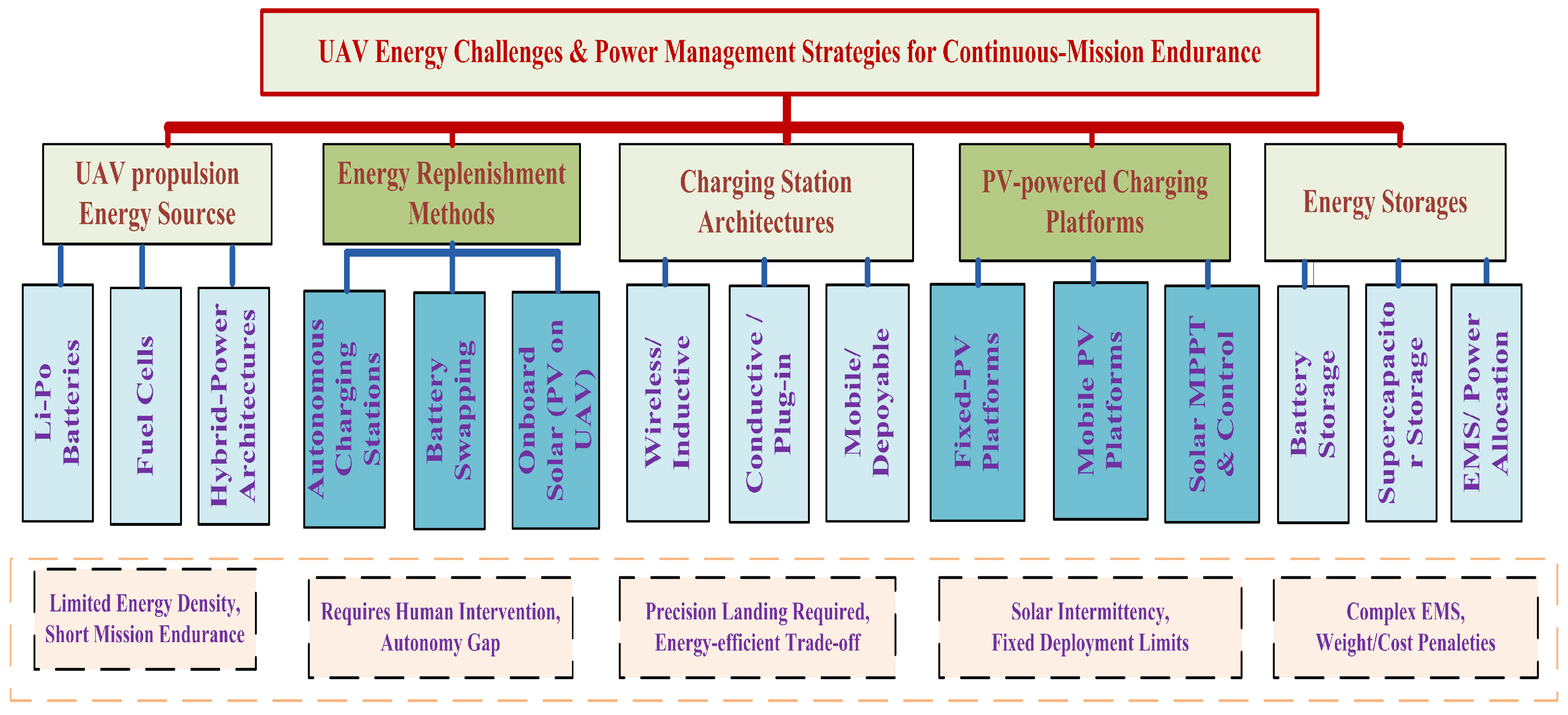
Figure 1. A taxonomy of the relevant literature on energy challenges and power management strategies in UAV Systems.
Technologies 14 00379 g001
Figure 2. A taxonomy of the relevant literature on lithium-ion battery charging strategies and UAV continuous-mission energy replenishment.
Technologies 14 00379 g002
Figure 3. The proposed mechatronic system.
Technologies 14 00379 g003
Figure 4. Flowchart of the priority-based power management algorithm for the PV–HESS charging station.
Technologies 14 00379 g004
Figure 5. Architecture of the proposed first-order Sugeno ANFIS used for generating the charging-current derating factor.
Technologies 14 00379 g005
Figure 6. The variation of the genrated, stored and consumed powers of the system.
Technologies 14 00379 g006
Figure 7. The net power exchanged by the hybrid energy storage system (HESS).
Technologies 14 00379 g007
Figure 8. The daily overview of the energy system.
Technologies 14 00379 g008
Figure 9. Battery label timeline per slot heatmap.
Technologies 14 00379 g009
Figure 10. LiPo SOC per charging slot.
Technologies 14 00379 g010
Figure 11. Daily CC-CV charging profiles for the three LiPo battery packs: (a) Slot-1; (b) Slot-2; (c) Slot-3.
Technologies 14 00379 g011
Figure 12. Charging and stop states over time.
Technologies 14 00379 g012
Figure 13. Full hold timers bfore swapping.
Technologies 14 00379 g013
Figure 14. The number of swapes after full holds for the three slots.
Technologies 14 00379 g014
Figure 15. Daily HESS SOC evolution demonstrating morning discharge, midday PV-driven recharge (SOC = 1), and controlled afternoon discharge to ensure robust and continuous agricultural UAV operation.
Technologies 14 00379 g015
Figure 16. Optimizer convergence characteristics for controller-parameter tuning using PSO and DE algorithms for: (a) PID optimizer convergence; (b) ANFIS optimizer convergence.
Technologies 14 00379 g016
Figure 17. The resulting training and validation root-mean-square error (RMSE) curves.
Technologies 14 00379 g017
Figure 18. The ANFIS 3-D control surface.
Technologies 14 00379 g018
Figure 19. The ANFIS control surface (Contour).
Technologies 14 00379 g019
Figure 20. Comparison of lifetime-related degradation indicators under ANFIS and PID temperature-limited charging strategies: (a) SOC-weighted thermal dose (b) Equivalent full cycles (EFC).
Technologies 14 00379 g020
Figure 21. Comparison of the RMSE and MAE errors in CC-mode currents for the two controllers (a) The RMSE comparison (b) The MAE comparison.
Technologies 14 00379 g021
Figure 22. The comparison reveals fundamental differences in how the two controllers manage electrothermal constraints during the charging process.
Technologies 14 00379 g022
Figure 23. Comparison of zoomed charging curves of the three packs for the two controllers.
Technologies 14 00379 g023
Figure 24. Pack voltage evolution for ANFIS and PID controllers over the zoomed window t [ 0 , 3000 ] s. The dotted horizontal line denotes the maximum allowable pack voltage V max = 12.6 V ( 3 × 4.2 V).
Technologies 14 00379 g024
Figure 25. Multi-KPI performance radar chart comparing the ANFIS and PID controllers across six normalized performance dimensions.
Technologies 14 00379 g025
Table 1. Comparison of the proposed framework with selected state-of-the-art EMS and charging strategies.
ReferenceMethodMulti-PackThermal LimiterHESSABR/SwapPV-Powered
Liu et al. [28]Electrothermal-aging CC–CVSingleRule-basedNoNoNo
Zhu et al. [38]MPC + RLSingleMPCNoNoNo
Liu et al. [40]Thermal-derated CCSingleLookupNoNoNo
Trivino et al. [44]Type-II FuzzyMultiNoneNoNoGrid
Vignesh et al. [49]ANFIS EMS (HEV)SingleNonePartialNoSolar
Guan et al. [29]Data-driven + rolloutSingleNoneNoNoNo
Ali et al. [58]CC–CV selectionMultiNoneNoYesSolar
Hu et al. [26]Data-driven HESS ctrlNoneNoneYesNoYes
Our proposed sysetmANFIS + Priority EMSMultiANFIS (T, dT/dt)YesYesYes
Table 2. System parameters for hybrid PV-battery–supercapacitor simulation.
CategoryParameterSymbolValueUnits
Control TargetDC-bus Voltage V d c r e f 50V
Load and SourceMax motor Power P L m a x 200 × 2W
Max LiPo Power P L m a x 60 × 3W
PV Rated Power P p v 775W
HESS—NiMHCapacity Q n 20 × 2Ah
HESS—SCCapacitance C s c 25F
DC-LinkDC-bus Capacitance C d c 100mF
Table 3. Lexicographic priority hierarchy of the proposed EMS.
PriorityLoadConditionPower Assigned
1ABR stepper motors u ABR ( k ) = 1 P ABR ( k ) = u ABR ( k ) P ABR , req
2LiPo charging (max-first) SOC i < SOC full , hold i = 0 Equations (4)–(6)
3BLDC propulsion u BLDC ( k ) = 1 , P av > 0 P BLDC ( k ) = min ( P BLDC , req , P av , 3 ( k ) )
4HESS (surplus/deficit)alwaysEquations (7) and (8)
Table 4. First-order Sugeno ANFIS rule base for current derating factor generation.
Temperature TTemperature Rate T ˙ = dT / dt
Negative ( N ) Zero ( Z ) Positive ( P )
Low (L) R 1 : f 1 R 2 : f 2 R 3 : f 3
Medium (M) R 4 : f 4 R 5 : f 5 R 6 : f 6
High (H) R 7 : f 7 R 8 : f 8 R 9 : f 9
Table 5. Quantitative comparison of ANFIS and PID controllers (PSO+DE optimized, t end = 3600 s). Bold values indicate the better result per metric.
CategoryMetricANFIS (PSO)PID (DE)
Pack 1 Pack 2 Pack 3 Pack 1 Pack 2 Pack 3
OptimizerPSO cost value89,570.9612,654.82
DE cost value89,592.8212,654.82
Selected algorithmPSODE
CC-mode
current
tracking
RMSE (A) 1.63 × 10 5 3.13 × 10 5 3.95 × 10 5 5.19 × 10 4 3.37 × 10 4 3.40 × 10 4
MAE (A) 6.78 × 10 6 1.11 × 10 5 1.55 × 10 5 4.28 × 10 5 2.98 × 10 5 2.99 × 10 5
CC samples7201 (all packs)7201 (all packs)
Thermal
performance
Peak temp. (°C)46.4346.0446.0545.9845.9745.97
Time above T knee (s)3449.53301.03302.53524.53435.53436.5
Time above 50 °C (s)3263.53058.53094.03441.03322.53324.0
Time near T max (s)000000
Thermal dose (s)15,50014,78314,82815,36315,17015,173
Charging
performance
Throughput (Ah)2.8182.8272.8212.7372.8232.815
EFC0.5420.5440.5430.5260.5430.541
I rms (A)2.8382.8512.8482.8092.8992.891
Peak C-rate0.8610.7960.7971.0000.9230.923
Peak SOC0.9420.7440.7230.9260.7430.721
SOC
thresholds
Time at SOC > 0.9 (s)288.500185.500
Time at SOC > 0.8 (s)9840089400
Lifetime
proxy
KPIs
SOC-wtd. thermal dose (s)20,63615,15815,06219,80715,53815,398
Damage index ( ) 20,69415,15815,06219,84415,53815,398
Mean damage index ( ) 1.70 × 10 4 1.69 × 10 4
Tknee = 41 °C, Tmax = 52 °C. EFC = equivalent full cycles. Done times: all packs still charging at t = 3600 s. Bold = better value per metric. ANFIS achieves ∼32× lower RMSE and higher peak SOC; PID shows marginally lower mean damage index (Δ ≈ 0.6%).
Table 6. Structured future work roadmap.
PhaseActivityTool/Platform
Phase 1HIL real-time simulationdSPACE DS1104/OPAL-RT OP4510
Phase 2Scaled laboratory prototypePV emulator + Li-ion battery pack
Phase 3DSP implementationTMS320F28379D (Texas Instruments)
Phase 4Real ANFIS retrainingRooftop PV measured T and G data
Phase 5Battery thermal validationThermal camera + current sensor
Disclaimer/Publisher’s Note: The statements, opinions and data contained in all publications are solely those of the individual author(s) and contributor(s) and not of MDPI and/or the editor(s). MDPI and/or the editor(s) disclaim responsibility for any injury to people or property resulting from any ideas, methods, instructions or products referred to in the content.