
A Parametric Blade Design Method for High-Speed Axial Compressor


Abstract
:1. Introduction
- 1.
- Flexibility
- 2.
- Local adjustability
- -
- Partial blade surface could be altered according to design needs while other parts of the airfoil are kept fixed, which is useful in blade optimizations.
- 3.
- Usability
- -
- The quantity of parameters is limited to a suitable level to make the method easy to use.
- -
- The parameters have clear, intuitive effects on the blade geometry [24].
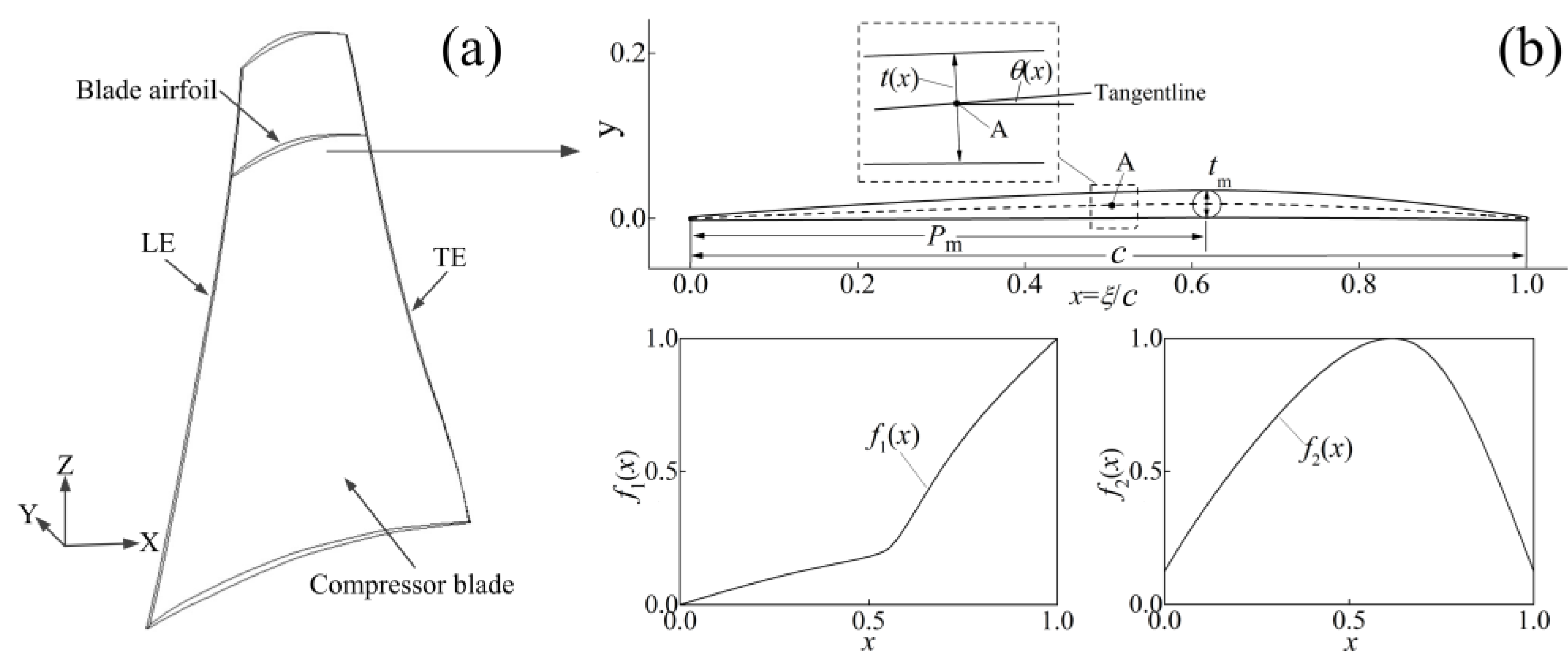
2. Two-Dimensional Blade Airfoil Design
2.1. Airfoil Definition
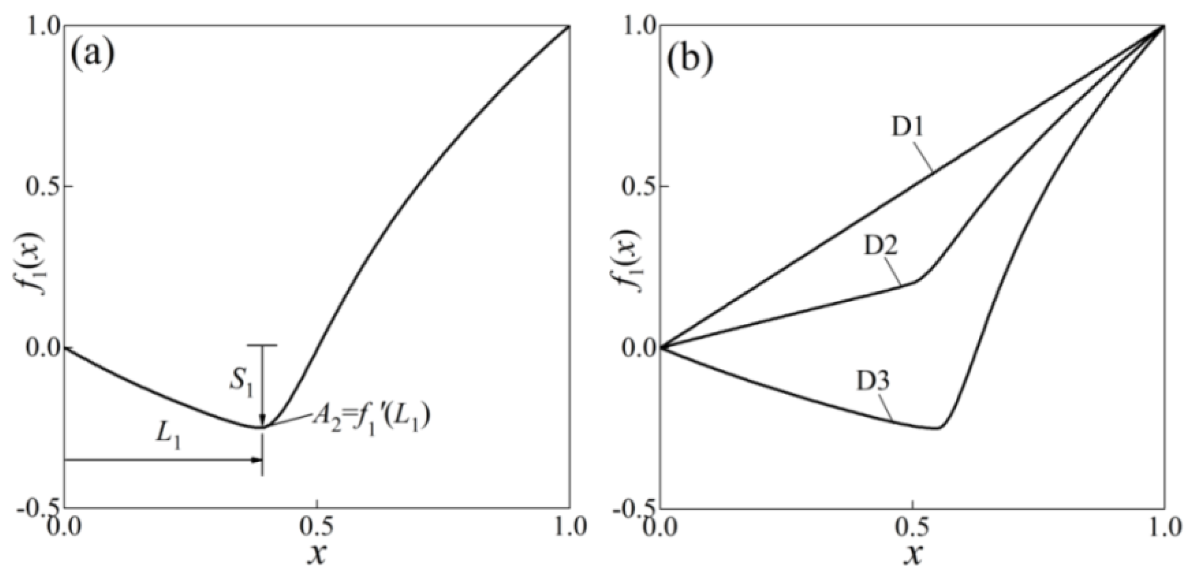
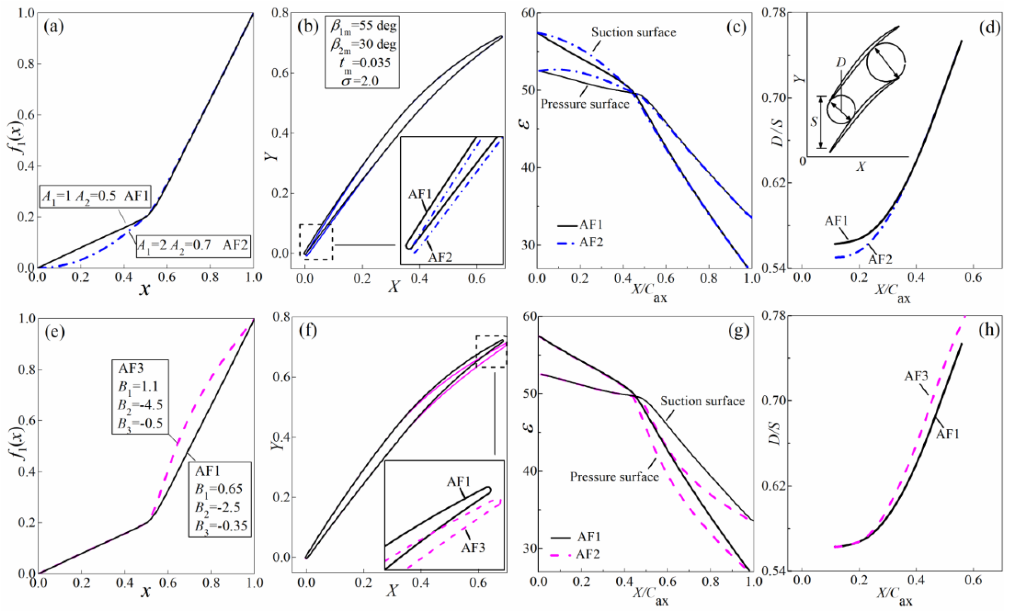
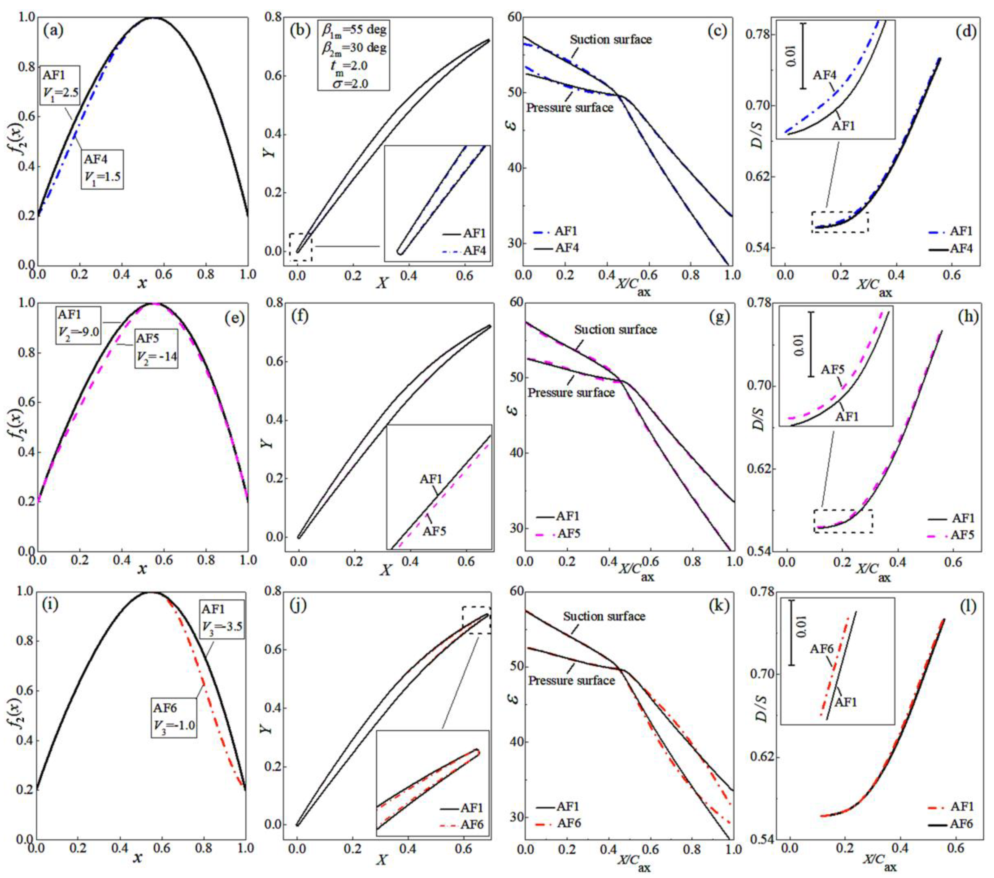
2.2. Normalized Camber Angle Distribution
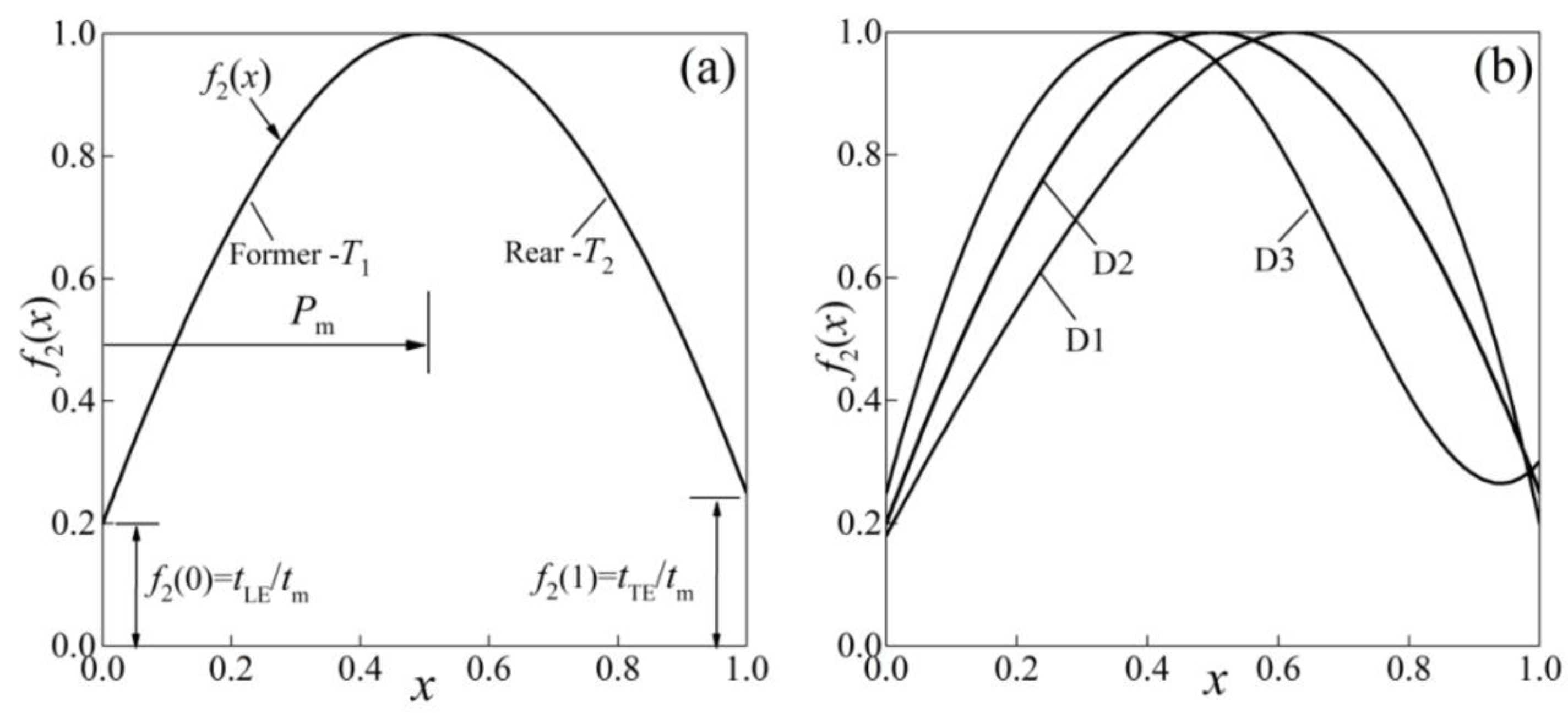
2.3. Normalized Thickness Distribution
3. From Airfoils to Three-Dimensional Blade Design
Stacking of Blade Element
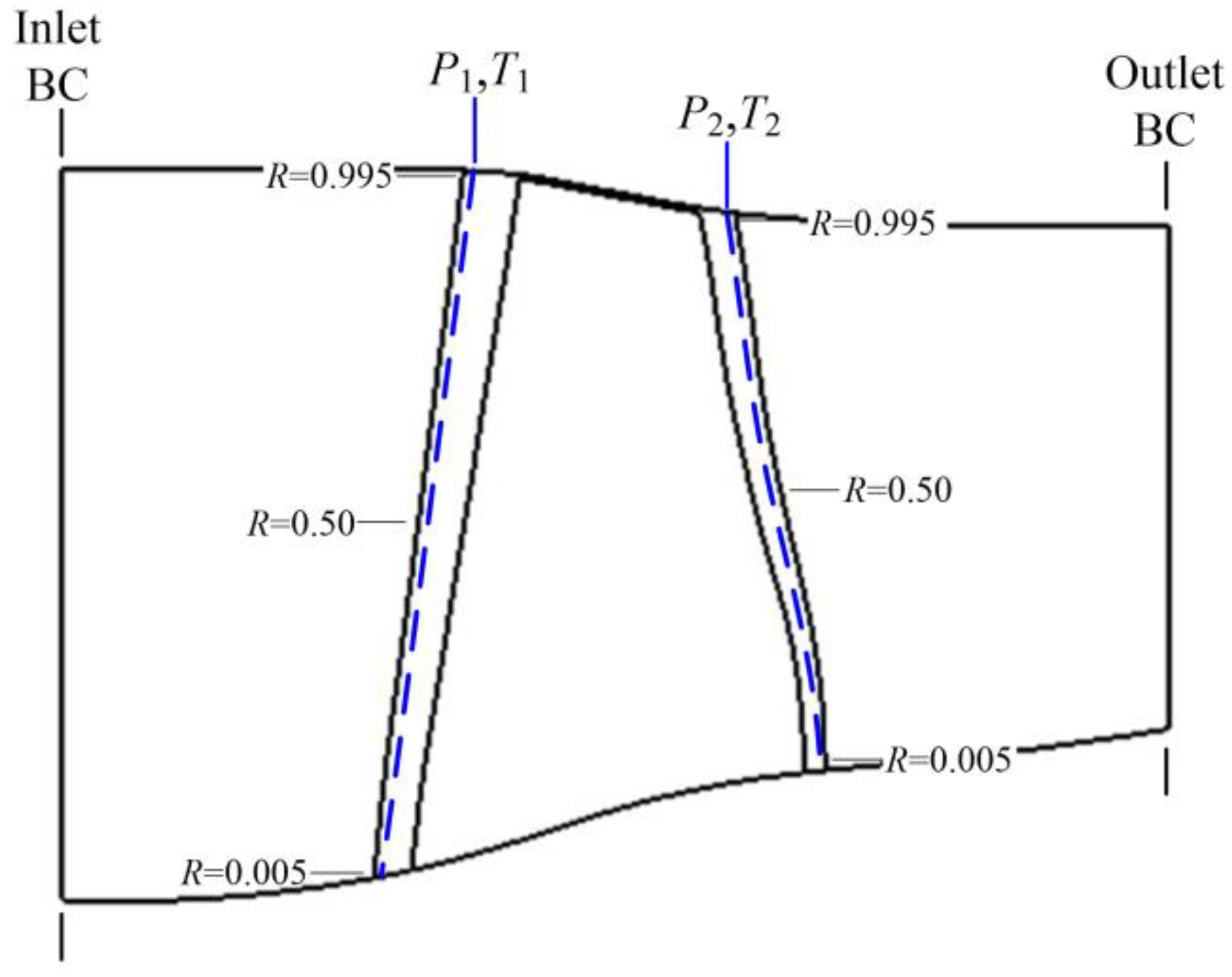
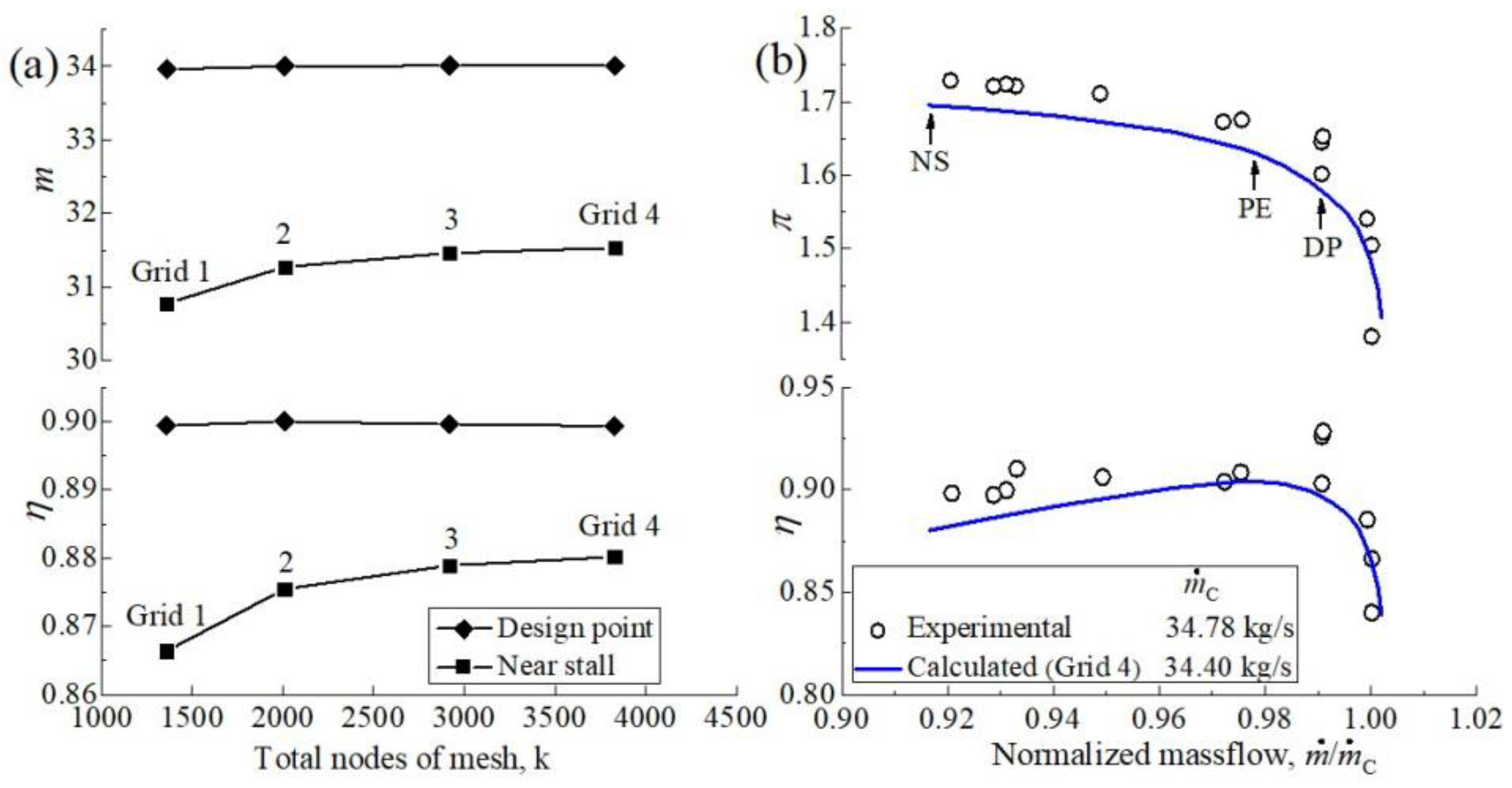
4. Numerical Simulation Method Verification
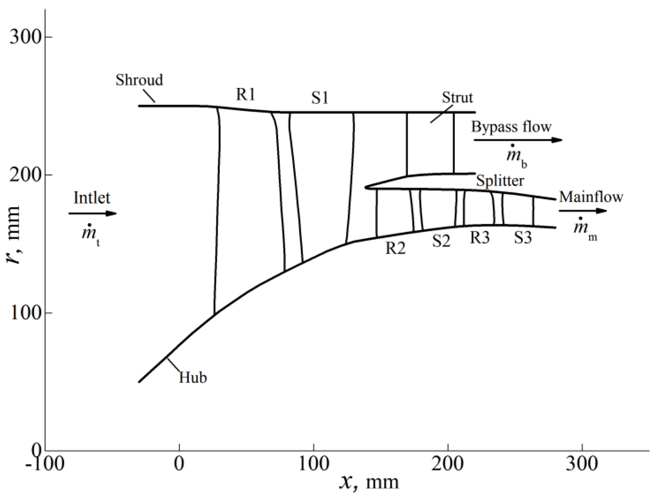
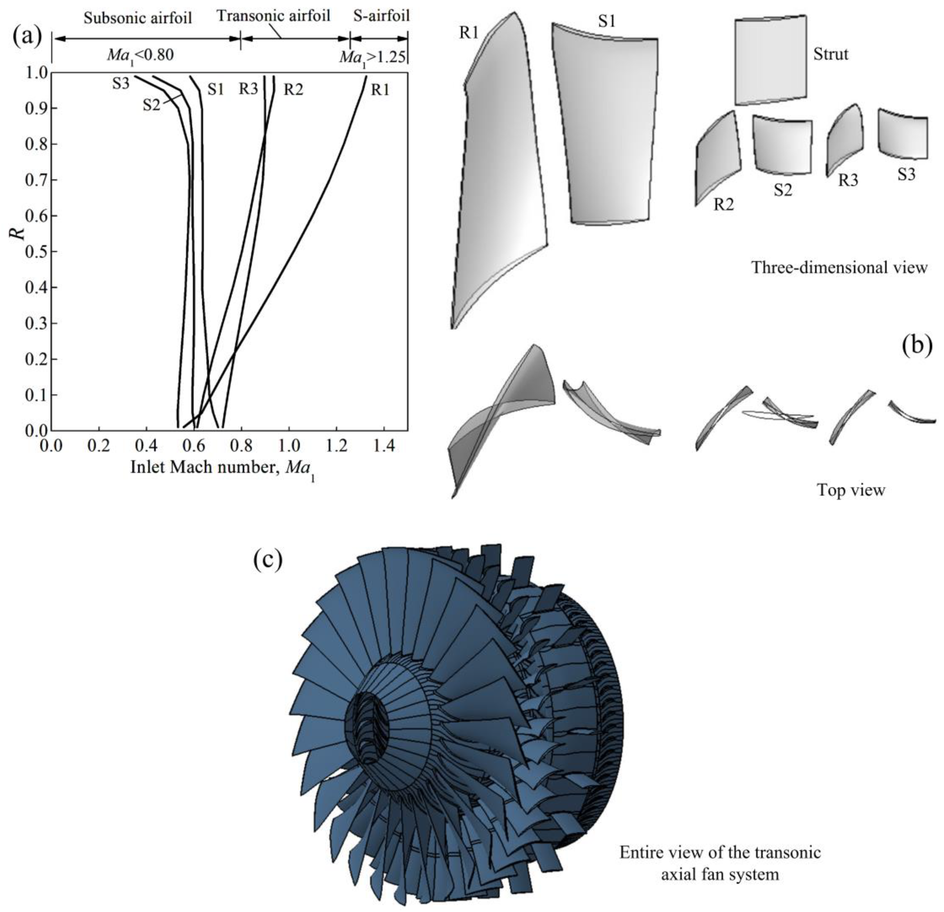
5. Application Case: Efficient Transonic Axial Fan Design
5.1. Introduction of the Transonic Axial Fan System
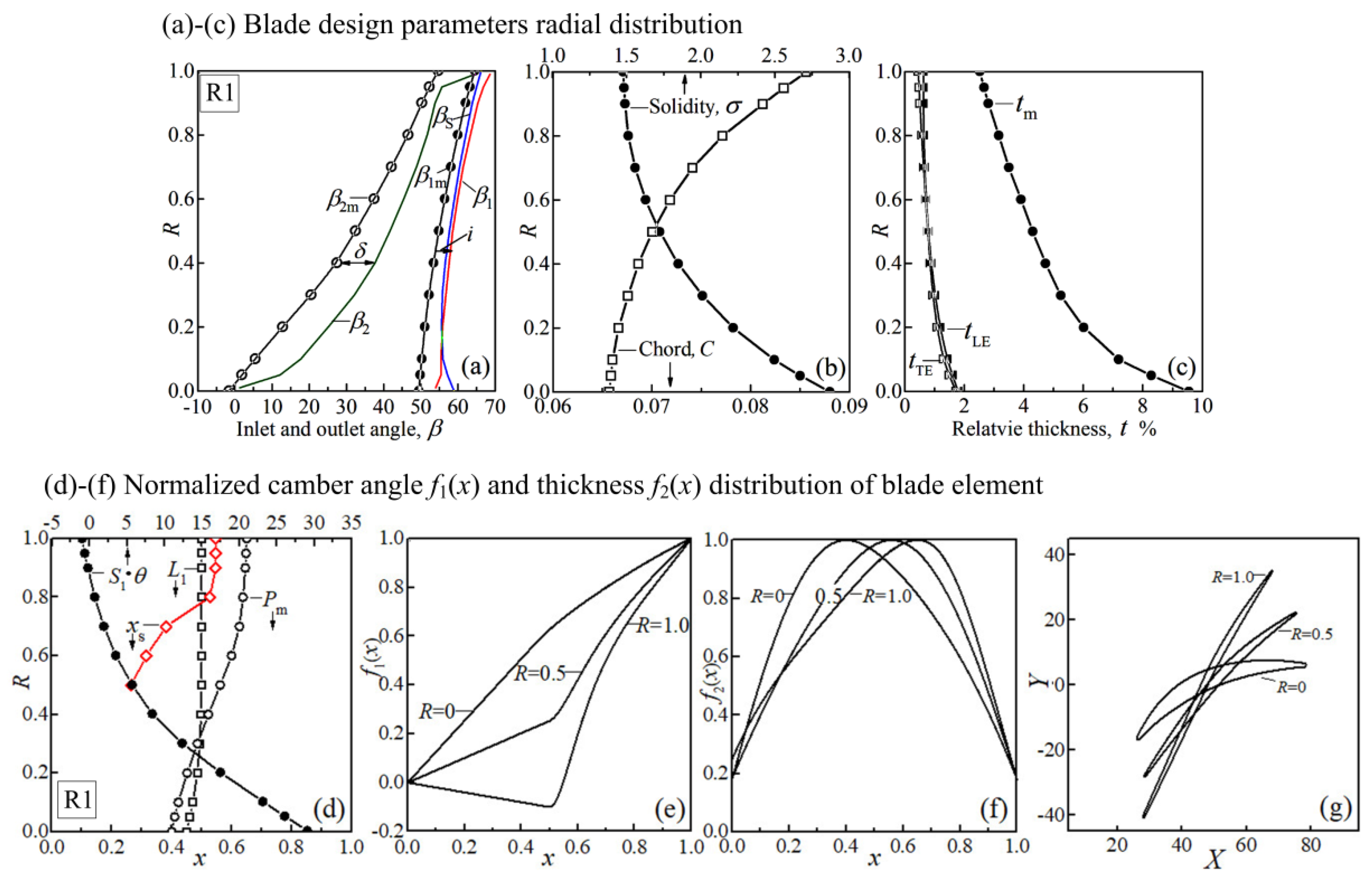
5.2. Blade Design
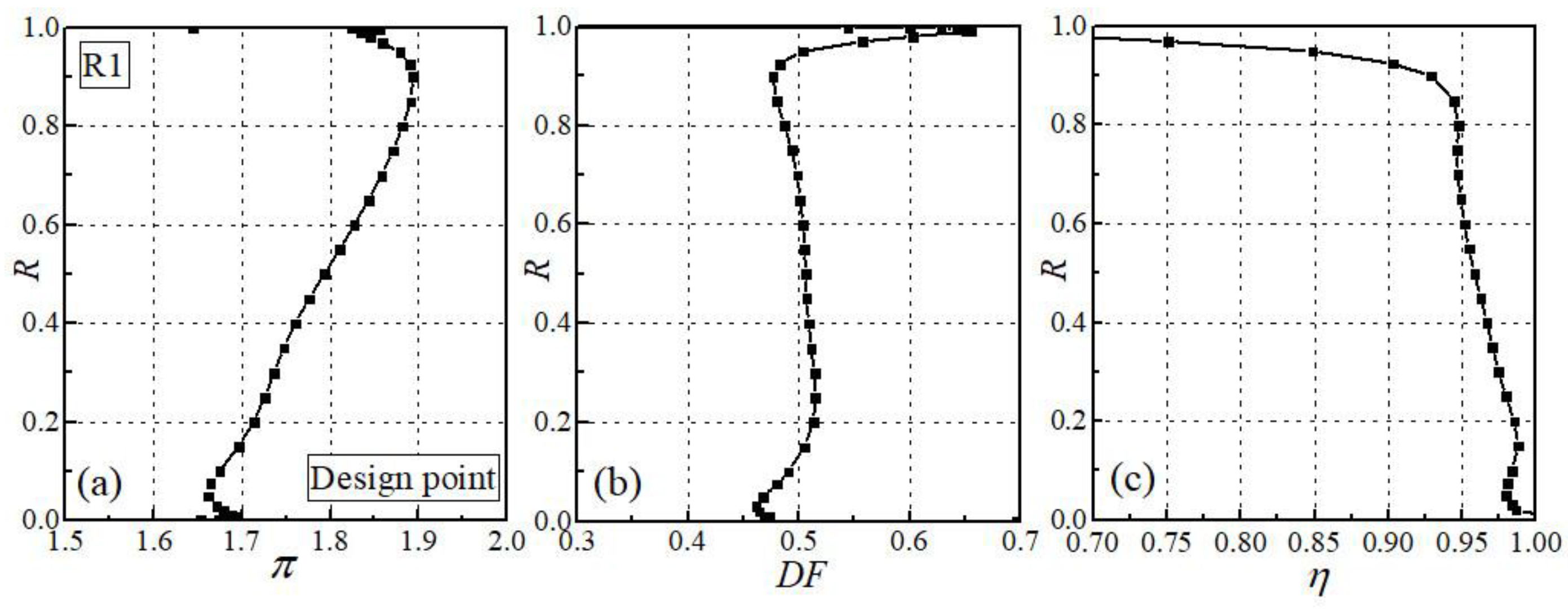
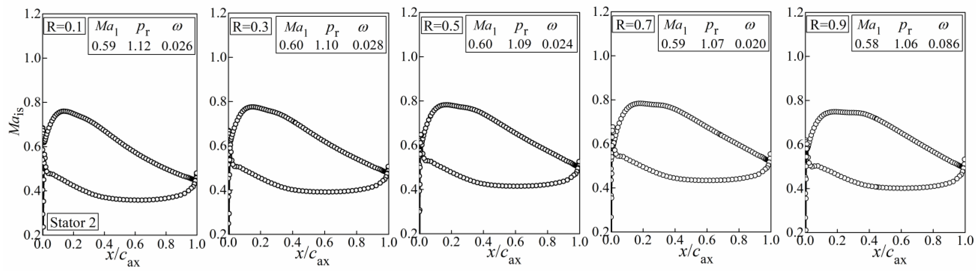
5.3. Aerodynamic Performance
6. Conclusions
Funding
Data Availability Statement
Conflicts of Interest
Abbreviations
| Airfoil aerodynamic chord (mm), length of straight-line connecting the origin point and terminal point of camber-line | |
| Mass flow rate ) | |
| Incidence angle, | |
| Specific heat ratio, k = 1.4 | |
| Static pressure (Pa) | |
| Static pressure ratio | |
| Radius (mm) | |
| Airfoil maximum relative thickness | |
| Leading edge relative thickness | |
| Trailing edge relative thickness | |
| Normalized coordinates in chord-wise direction, | |
| Normalized coordinates in direction perpendicular to chord-wise | |
| Centerline coordinates in direction perpendicular to chord-wise | |
| Airfoil chord (mm) | |
| D | Diameter of blade passage inscribed circle |
| DF | Diffusion factor, for rotor; for stator |
| LE | Leading edge |
| Mach number | |
| Relative rotating speed, the ratio of actual rotating speed to design rotating speed | |
| Total pressure (Pa) | |
| Maximum thickness chord-wise location | |
| Blade relative height | |
| Total pressure recovery coefficient, | |
| Spacing (mm) | |
| Total temperature (K) | |
| TE | Trailing edge |
| Axial coordinates (mm) | |
| Normalized axial coordinates | |
| Tangential coordinates (mm) | |
| Radial coordinates (mm) | |
| Deviation angle (degree) | |
| Flow angle measured from axial direction (degree) | |
| Blade metal angle measured from axial direction (degree) | |
| Blade LE suction surface angle measured from axial direction (degree), | |
| Blade surface angle, the angle between surface tangent line and axial direction (degree) | |
| Adiabatic efficiency, | |
| Camber angle (degree) | |
| Leading edge construction angle (degree) | |
| Flow coefficient, | |
| Suction surface incidence angle, | |
| Load coefficient, | |
| Coordinates in chord-wise direction (mm) | |
| Total pressure ratio, | |
| Solidity, | |
| Displacement distance of airfoil center of gravity for sweep | |
| Displacement distance of airfoil center of gravity for bow |
Subscripts
| 1 | Inlet |
| 2 | Outlet |
| ax | Axial direction |
| is | Isentropic |
| C | Chocked |
| D | Value at design work condition |
| SG | Staggered |
Appendix A
Appendix A.1. The Derivation of Sub-Function and from Basic Polynomial
References
- Biollo, R.; Benini, E. Recent advances in transonic axial compressor aerodynamics. Prog. Aerosp. Sci. 2013, 56, 1–18. [Google Scholar] [CrossRef]
- Wadia, A.R.; Law, C.H. Low Aspect Ratio Transonic Rotors: Part 2—Influence of Location of Maximum Thickness on Transonic Compressor Performance. ASME J. Turbomach. 1993, 115, 226–239. [Google Scholar] [CrossRef]
- Wadia, A.R.; Copenhaver, W.W. An Investigation of the Effect of Cascade Area Ratios on Transonic Compressor Performance. ASME J. Turbomach. 1996, 118, 760–770. [Google Scholar] [CrossRef]
- Von der Bank, R.; Donnerhack, S.; Rae, A.; Poutriquet, F.; Lundbladh, A.; Antoranz, A.; Tarnowski, L.; Ruzicka, M. Compressors for ultra-high-pressure-ratio aero-engines. CEAS Aeronaut. J. 2016, 7, 455–470. [Google Scholar] [CrossRef]
- Morris, A.L.; Halle, J.E.; Kennedy, E. High-Loading, 1800 ft/sec Tip Speed Transonic Compressor Fan Stage, Aerodynamic and Mechanical Design; NASA Lewis Research Center: Cleveland, OH, USA, 1972. [Google Scholar]
- Frost, G.R.; Hearsey, R.; Wennerstrom, A. A Computer Program for the Specification of Axial Compressor Airfoils; Aerospace Research Laborataries, Wright-Patterson Air Force Base: Montgomery County, OH, USA, 1972. [Google Scholar]
- Frost, G.R.; Wennerstrom, A.J. The Design of Axial Compressor Airfoils Using Arbitrary Camber Lines; Aerospace Research Laboratories, Wright-Patterson Air Force Base: Montgomery County, OH, USA, 1973. [Google Scholar]
- Wennerstrom, A.J.; Frost, G.R. Design of a 1500 ft/sec, Transonic, High-Through-Flow, Single-Stage Axial Flow Compressor with Low Hub/Tip Ratio; Air Force Aero-Propulsion Laboratory, Wright-Patterson Air Force Base: Montgomery County, OH, USA, 1976. [Google Scholar]
- Wennerstrom, A.J.; Derose, R.D.; Law, C.H.; Buzzell, W.A. Investigation of a 1500 ft/sec, Transonic, High through-flow, Single-Stage Axial-Flow Compressor with Low Hub/Tip Ratio; Air Force Aero-Propulsion Laboratory, Wright-Patterson Air Force Base: Montgomery County, OH, USA, 1976. [Google Scholar]
- Korakianitis, T. Prescribed-Curvature Distribution Airfoils for the Preliminary Geometric Design of Axial Turbomachinery Cascades. ASME J. Turbomach. 1993, 115, 325–333. [Google Scholar] [CrossRef]
- Kulfan, B. Universal Parametric Geometry Representation Method. J. Aircr. 2008, 45, 142–158. [Google Scholar] [CrossRef]
- Kulfan, B.M. A Universal Parametric Geometry Representation Method-“CST”. In Proceedings of the 45th AIAA Aerospace Sciences Meeting and Exhibit, Reno, NV, USA, 8–11 January 2007. [Google Scholar]
- Schreiber, H.A.; Starken, H. Experimental Cascade Analysis of a Transonic Compressor Rotor Blade Section. ASME J. Eng. Gas Turbines Power 1984, 106, 288–294. [Google Scholar] [CrossRef]
- Sonoda, T.; Olhofer, M.; Arima, T.; Sendhoff, B. A NEW CONCEPT OF A TWO-DIMENSIONAL SUPERSONIC RELATIVE INLET MACH NUMBER COMPRESSOR CASCADE. In Proceedings of the ASME Turbo Expo 2009: Power for Land, Sea and Air, Orlando, FL, USA, 8–12 June 2009. [Google Scholar]
- Venturelli, G.; Benini, E. Kriging-assisted design optimization of S-shape supersonic compressor cascades. Aerosp. Sci. Technol. 2016, 58, 275–297. [Google Scholar] [CrossRef]
- Oyama, A.; Liou, M.-S.; Obayashi, S. Transonic Axial-Flow Blade Optimization: Evolutionary Algorithms/Three-Dimensional Navier–Stokes Solver. J. Propuls. Power 2004, 20, 612–619. [Google Scholar] [CrossRef] [Green Version]
- Wang, D.X.; He, L. Adjoint Aerodynamic Design Optimization for Blades in Multistage Turbomachines—Part I: Methodology and Verification. ASME J. Turbomach 2010, 132, 021011. [Google Scholar] [CrossRef]
- Wang, D.X.; He, L.; Li, Y.S.; Wells, R.G. Adjoint Aerodynamic Design Optimization for Blades in Multistage Turbomachines—Part II: Validation and Application. ASME J. Turbomach. 2010, 132, 021012. [Google Scholar] [CrossRef]
- Denton, J.; Xu, L. The effects of lean and sweep on transonic fan performance. In Proceedings of the ASME Turbo Expo, Amsterdam, The Netherland, 3–6 June 2002. [Google Scholar]
- Iwatani, J.; Ito, E.; Owaki, T.; Nagai, N.; Seki, N. Development of compressor transonic rotor for the next generation gas turbine. In Proceedings of the IGTC2007, Tokyo, Japan, 2–7 December 2007. [Google Scholar]
- Ilikan, A.N.; Ayder, E. Influence of the Sweep Stacking on the Performance of an Axial Fan. ASME J. Turbomach. 2015, 137, 061004. [Google Scholar] [CrossRef]
- Adjei, R.A.; Fan, C.; Wang, W.; Liu, Y. Multidisciplinary Design Optimization for Performance Improvement of an Axial Flow Fan Using Free-Form Deformation. ASME J. Turbomach 2021, 143, 011003. [Google Scholar] [CrossRef]
- Schnell, R.; Zhao, X.; Rallis, E.; Kavvalos, M.; Sahoo, S.; Schnoes, M.; Kyprianidis, K. Assessment of a Turbo-Electric Aircraft Configuration with Aft-Propulsion Using Boundary Layer Ingestion. Aerospace 2019, 6, 134. [Google Scholar] [CrossRef] [Green Version]
- Sóbester, A.; Forrester, A.I.J. Aircraft Aerodynamic Design Geometry and Optimization, Chapter 5: Aerofoil Engineering: Fundamentals; John Wiley & Sons, Ltd,: West Sussex, UK, 2015. [Google Scholar]
- Schreiber, H.A. Experimental Investigations on Shock Losses of Transonic and Supersonic Compressor Cascades, AGARD Confrrence Proceedings No.40 I; Advisory Group for Aerospace Research and Development: Neuilly Sur Seine, France, 1987. [Google Scholar]
- Liu, B.; Shi, H.; Yu, X. A new method for rapid shock loss evaluation and reduction for the optimization design of a supersonic compressor cascade. Proc. IMechE Part G J. Aerosp. Eng. 2018, 232, 2458–2476. [Google Scholar] [CrossRef]
- Yang, J.; Ning, T.; Xi, P. Geometric generating method of blade profiles on arbitrary rotary flow surfaces. Acta Aeronaut. Astronaut. Sin. 2015, 36, 3483–3493. [Google Scholar]
- Gümmer, V.; Wenger, U.; Kau, H.-P. Using Sweep and Dihedral to Control Three-Dimensional Flow in Transonic Stators of Axial Compressors. ASME J. Turbomach. 2001, 123, 40–48. [Google Scholar] [CrossRef]
- Passrucker, H.; Engber, M.; Kablitz, S.; Hennecke, D.K. Effect of forward sweep in a transonic compressor rotor. Proc. IMechE Part A J. Power Energy 2003, 217, 357–365. [Google Scholar] [CrossRef]
- Zhang, J.; Zhuang, H.; Teng, J.; Zhu, M.; Qiang, X. Aerodynamic optimization to tandem stators by using sweep and dihedral. Proc. IMechE Part G J. Aerosp. Eng. 2020, 234, 1225–1236. [Google Scholar] [CrossRef]
- Urasek, D.C.; Gorrell, W.T.; Cunnan, W.S. Performance of Two-Stage Fan Having Low-Aspect-Ratio, First-Stage Rotor Blading; Lewis Research Center, NASA: Cleveland, OH, USA, 1979; p. 131. [Google Scholar]
- Strazisar, A.J.; Wood, J.R.; Hathaway, M.D.; Suder, K.L. Laser Anemometer Measurements in a Transonic Axial-Flow Fan Rotor; Lewis Research Center, NASA: Cleveland, OH, USA, 1989; p. 214. [Google Scholar]
- Wright, P.I.; Miller, D.C. An Improved Compressor Performance Prediction Model. In Proceedings of the European Conference of Turbomachinery: Latest Developments in a Changing Scene, London, UK, 19–20 March 1991. [Google Scholar]
- Dickens, T.; Day, I. The Design of Highly Loaded Axial Compressors. ASME J. Turbomach 2011, 133, 031007. [Google Scholar] [CrossRef]
- Lieblein, S.; Schwenk, F.C.; Broderick, R.L. Diffusion Factor for Estimating Losses and Limiting Blade Loadings in Axial-Flow-Compressor Blade Elements; Lewis Flight Propulsion Laboratory: Cleveland, OH, USA, 1953. [Google Scholar]


| Strength Coefficient | Location Coefficient | Adjustable Coefficients | |
|---|---|---|---|
| LE&TE Relative Thickness | Maxim. Thickness Location | Adjustable Coefficients | |||
|---|---|---|---|---|---|
| Topology Parameter | Grid 1 | Grid 2 | Grid 3 | Grid 4 |
|---|---|---|---|---|
| Stream-wise nodes | 89 | 129 | 169 | 209 |
| Pitch-wise nodes | 69 | 81 | 101 | 113 |
| Pitch-wise nodes across the O-block | 21 | 29 | 37 | 45 |
| Radial nodes | 61 | |||
| Total nodes of mesh | 1356 k | 2008 k | 2917 k | 3828 k |
| Flow Coefficient, | Load Coefficient, | |
|---|---|---|
| Stage 1 | 0.36 | 0.34 |
| Stage 2 | 0.50 | 0.32 |
| Stage 3 | 0.55 | 0.33 |
Publisher’s Note: MDPI stays neutral with regard to jurisdictional claims in published maps and institutional affiliations. |
© 2021 by the author. Licensee MDPI, Basel, Switzerland. This article is an open access article distributed under the terms and conditions of the Creative Commons Attribution (CC BY) license (https://creativecommons.org/licenses/by/4.0/).
Share and Cite
Shi, H. A Parametric Blade Design Method for High-Speed Axial Compressor. Aerospace 2021, 8, 271. https://doi.org/10.3390/aerospace8090271
Shi H. A Parametric Blade Design Method for High-Speed Axial Compressor. Aerospace. 2021; 8(9):271. https://doi.org/10.3390/aerospace8090271
Chicago/Turabian StyleShi, Hengtao. 2021. "A Parametric Blade Design Method for High-Speed Axial Compressor" Aerospace 8, no. 9: 271. https://doi.org/10.3390/aerospace8090271
APA StyleShi, H. (2021). A Parametric Blade Design Method for High-Speed Axial Compressor. Aerospace, 8(9), 271. https://doi.org/10.3390/aerospace8090271