Article

Experimental Validation for the Performance of MR Damper Aircraft Landing Gear

1
School of Aerospace and Mechanical Engineering, Korea Aerospace University, Goyang-si 10540, Korea
2
Aviation Certification Headquarters, Korea Institute of Aviation Safety Technology, Incheon 22851, Korea
*
Author to whom correspondence should be addressed.
Aerospace 2021, 8(9), 272; https://doi.org/10.3390/aerospace8090272
Submission received: 18 August 2021 / Revised: 17 September 2021 / Accepted: 18 September 2021 / Published: 19 September 2021
(This article belongs to the Special Issue Vibration Control for Space Application)

Abstract

:
The landing gear of an aircraft serves to mitigate the vibration and impact forces transmitted from the ground to the fuselage. This paper addresses magneto-rheological (MR) damper landing gear, which provides high shock absorption efficiency and excellent stability in various landing conditions by adjusting the damping force using external magnetic field intensity. The performance and stability of an MR damper was verified through numerical simulations and drop tests that satisfied aviation regulations for aircraft landing gear. In this study, a prototype MR damper landing gear, a drop test jig, and a two-degree-of-freedom model were developed to verify the performance of the MR damper, with real-time control, for light aircraft landing gear. Two semi-active control algorithms, skyhook control and hybrid control, were applied to the MR damper landing gear. The drop tests were carried out under multiple conditions, and the results were compared with numerical simulations based on the mathematical model. It was experimentally verified that as the shock absorption efficiency increased, the landing gear’s cushioning performance significantly improved by 17.9% over the efficiency achieved with existing passive damping.

Graphical Abstract

1. Introduction

An aircraft’s landing gear supports its fuselage on the ground and mitigates the vibration and shock transmitted to the fuselage during landing and taxiing [1,2,3,4]. Aircraft are commonly set up with traditional passive oleo-pneumatic landing gear that delivers high shock absorption efficiency [5]. However, it is difficult for passive landing gear to satisfy the optimal performance specifications of various landing situations outside of design conditions. Semi-active landing gear systems offer the advantages of both passive and active systems [6,7,8]. Similar to active systems, they are able to adjust their damping force according to the control input, and they also ensure stability by reverting to passive mode when control is not possible. To provide an adjustable damping force, some semi-active landing gear designs incorporate a variable orifice [9] that regulates the orifice area through which the fluid flows during damper motion, and the magneto-rheological (MR) damper landing gear utilizes MR fluid that produces yield stress under a magnetic field [10]. MR damper landing gear systems are seen as advantageous due to their simple structures, relatively large controllable forces, and fast responses to control input. In addition to their use in aircraft landing gear designs [11,12,13,14,15,16,17], MR dampers have been applied to a multitude of applications for the attenuation of shock and vibration, including vehicle suspension systems, clutches, brakes, and seismic design structures [18,19,20,21].
The performance and stability of newly developed aircraft landing gear are evaluated through drop tests, which are previously verified through numerical simulations. Multiple numerical drop test simulations are performed with a mathematical model of the landing gear to analyze the dynamical behavior and predict the structural loads that are borne during landing. As a model of the landing gear, a simple two-degree-of-freedom system is commonly used, where the dynamic equation incorporates the internal and external forces acting on the landing gear [22,23]. This simplifies the complex behavior of the system. Experiments are performed with a landing gear prototype and a drop test jig [24]; which are designed to satisfy test conditions and accommodate the sensors required for the semi-active control system. The landing gear prototype should be designed and manufactured to ensure structural safety during and after repeated experiments without leakage. The performance of the MR damper landing gear can be verified by investigating the characteristics of the MR damper using the drop test jig with real-time control over the damper [25,26].
Various control methods have been proposed, as control algorithms for MR damper landing gear, including the skyhook, hybrid, sliding mode, and neural network methods. Skyhook control, which has been shown to be effective in vehicle suspension design, has been applied to MR damper landing gears to improve their performance through simulations [16,27]. The hybrid control method is a combination of skyhook and force control, and it was initially proposed to obtain higher shock absorption efficiency than skyhook control alone when applied to MR damper landing gear [28,29]. An adaptive controller was also investigated as a method for the consideration of conditions such as sprung mass, sink speed, operating temperature, and the MR fluid damping coefficient [30,31]. In addition, a neural network controller capable of maintaining performance goals in various landing situations was applied to an MR damper landing gear design [32]. However, although theoretical studies have been continually conducted with mathematical models of MR damper landing gear designs, it is critical to carry out actual experiments to verify the performance of these control techniques in practical landing situations. To the best of the authors’ knowledge, no studies have been published that experimentally verify the performance of an MR damper landing gear configuration in terms of shock absorption efficiency, with a prototype, in a drop test environment.
For this study, a 1/3-scale MR damper landing gear prototype and a drop test jig were constructed, and we performed drop tests comparing the numerical simulations with two-degree-of-freedom modeling. The prototype was based on the scale and performance of the main landing gear used for the Beechcraft Baron 55, and sensors were installed for real-time control. The characteristics of the MR damper were analyzed with and without applying the skyhook and hybrid control to the damper as semi-active control algorithms. Drop test experiments were conducted on various conditions of the sprung mass and sink speed with a real-time control system, and this experimentally verified that the MR damper landing gear’s performance significantly improved when the semi-active control algorithms were applied.
The structure of the paper is arranged as follows. Section 2 shows the design and modeling of a single landing gear equipped with an MR damper. Section 3 describes the prototype, drop test jig, and data acquisition system. The drop test experiment is explained in Section 4; Section 5 details and analyzes the experiment results, and conclusions are provided in Section 6.

2. MR Damper Landing Gear

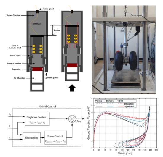
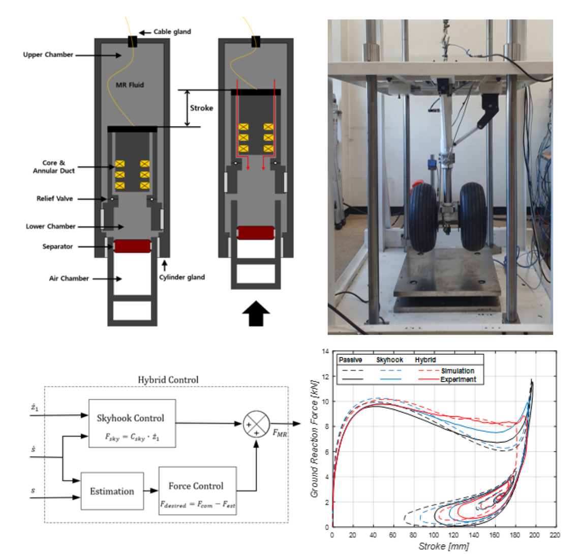
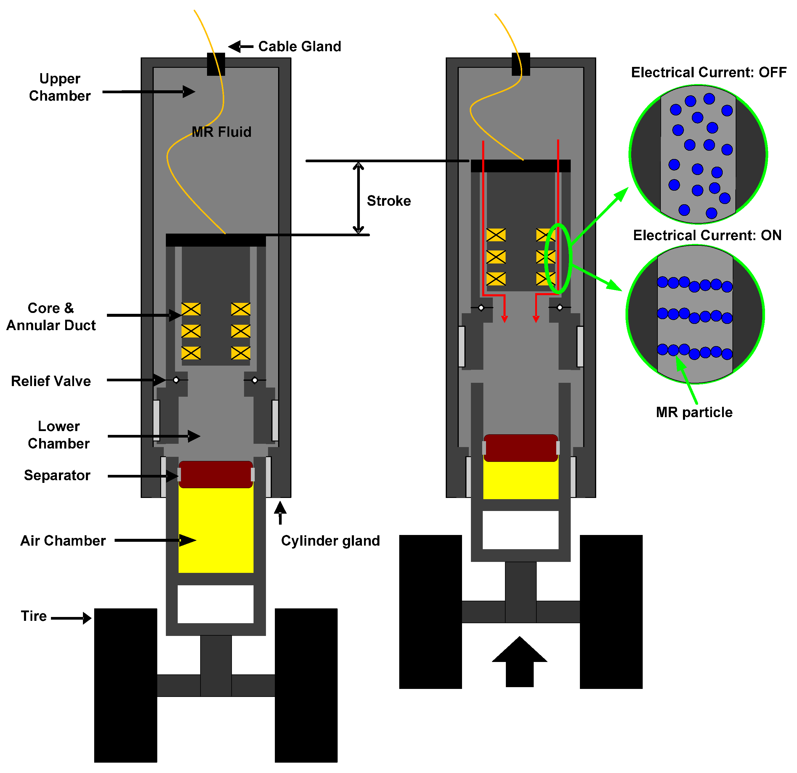
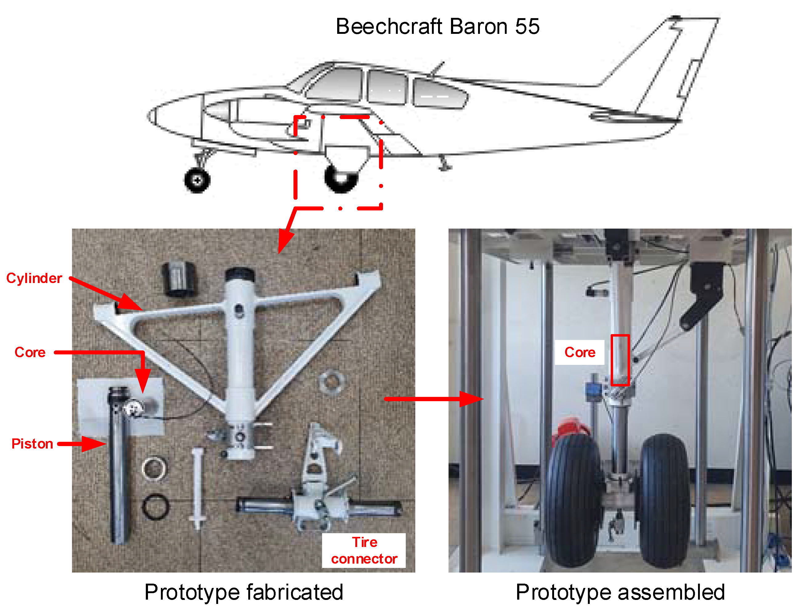
2.1. Structure of MR Damper Landing Gear

With MR damper landing gear, the damping force can be adjusted depending on the magnetic field strength of the passage where MR fluid flows with the damper’s motion. The MR damper landing gear’s structure is similar to that of a conventional passive oleo-pneumatic landing gear setup, except it features an annular cross-sectional flow passage in the piston to maximize the properties of the MR fluids. The cross-sectional view of the structure of the MR damper landing gear covered in this study, as well as the fluid flows at each compression phase, are shown in Figure 1. As the piston moved through the compression and extension phases of the damper, MR fluid flowed through the narrow annular passage in the piston and thus caused a pressure drop downstream due to the viscosity of the fluid. Multiple coils were wound inside the piston, forming several poles, surrounded by the annular passage. The magnetic field was formed in the passage by controlling the current flowing through the coils. The wire that supplied the current to the coils was connected to an external power amplifier passing through the upper chamber and the upper cap gland of the cylinder. As the magnetic field formed across the passage, micro-particles of MR fluid were aligned so that the system produced yield stress proportional to the field and provided additional damping force.
The piston and cylinder moved with high-pressure seals between them. These seals minimized the friction and incorporated an O-ring to prevent leakage and a scraper to protect the piston’s outer wall. A lightweight separator with a seal inside the piston was installed to prevent fluid leakage from the lower chamber to the air chamber. The volume of the fluid flowing between the upper and lower chambers with the movement of the damper was offset by the air chamber’s volume change. Thus, for example, as the piston moved up, the MR fluid flowed into the lower chamber, and the air chamber was compressed by the same volume of fluid entering into the lower chamber. This caused a pressure rise in the lower chamber and the air chamber, and thereby provided the damper with an elastic force. Notably, the upper chamber pressure was higher than the lower chamber pressure since the piston pushed the fluid of the upper chamber through the passage, and pressure loss occurred due to the viscosity and yield stress. When the damper was extended, the lower chamber pressure was higher, so that the fluid flowed to the upper chamber, and a ring-shaped relief valve around the side of the piston was opened. The fluid subsequently flowed through the passage between the piston and the inner wall of the cylinder, and thus a much smaller amount of damping force was applied in the extension phase. This prevented the tires from bouncing and detaching from the ground.

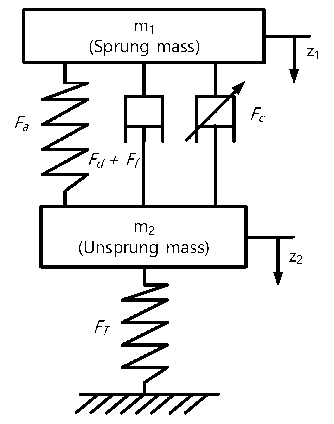
2.2. Mathematical Model

The two-degree-of-freedom system model for the dynamics of the MR damper landing gear is expressed as an equation of motion, as follows:
m 1 z ¨ 1 = ( F a + F d + F f ) + m 1 g m 2 z ¨ 2 = ( F a + F d + F f ) F T + m 2 g
m 1 and m 2 are the sprung mass and unsprung mass, respectively, z 1 and z 2 are the corresponding displacements, F T is the tire reaction force from the ground, and g is the gravitational acceleration. F s is the strut force, which is composed of the compressed air force ( F a ) from the air chamber, the damping force ( F d ), and the friction force ( F f ) between the piston and the cylinder, as shown in Figure 2.
F s = F a + F d + F f
The shock absorption efficiency used in this study can be described as follows:
E   [ % ] = 0 s max F s   ds F s ,   max · s max × 100
where s = z 1 z 2 is the stroke of the damper, i.e., the relative displacement of the cylinder and piston. The shock absorption efficiency can be expressed as the ratio of energy dissipated by the landing gear to the total mechanical energy of the aircraft just before making contact with the ground. It is calculated by integrating the force from the initial stroke with the stroke of the maximum compression. Thus, the shock absorption efficiency can be characterized using the strut force-stroke diagram, which can be seen in Figure 3. As the shape of the diagram is to the square shape, the obtained efficiency increased.
When modeling a damper, the internal and external forces applied to the damper need to be specified. Immediately after the landing gear touches the ground, the tire reaction force and thus the strut force acting between the piston and the cylinder are applied. First, the air pressure in the air chamber forms the air force, which can be expressed as follows [1]:
F a = A a [ P a 0 ( V 0 V 0 A a · s ) n P ATM ]  
In this equation, P a 0 and V 0 are the initial pressure and volume of the air chamber, respectively, A a is the piston’s cross-sectional area, including the outer wall, P ATM is the atmospheric pressure, and n is the polytropic index.
The total damping force ( F d ) acting on the MR damper landing gear consists of the hydraulic force ( F h ) that occurs due to the pressure drop with the fluid viscosity, and the controllable force ( F c ) that occurs due to the yield stress of the MR fluid via the magnetic field that develops in the passage of the piston. The hydraulic force is asymmetrically applied during the compression and extension phases via the relief valves used in the landing gear. Because the entrance length through the annular passage where the developing flow appears is not negligible compared to the total length of the passage, the developing flow in the annular pipe is considered in the modeling of the hydraulic force due to the viscosity [23].
F h comp = A p [ 5.995 μ L π R 1 t 1 3 Q + 0.3436 ρ ( Q A 1 ) 2 ] F h ext = A p [ [ ( 5.995 μ L π R 1 t 1 3 + 0.3436 ρ Q A 1 2 ) 1 + ( 5.998 μ L π R 2 t 2 3 + 0.3430 ρ Q A 2 2 ) 1 ] 1 ]   Q
A 1 and A 2 are the cross-sectional areas of the annular passages inside and outside the piston, R 1 and R 2 are the center radii of the annular passages, and t 1 and t 2 are the gap sizes of the annular passages. L is the total passage length, A p is the cross-sectional area of the piston excluding the outer wall, and μ , ρ , and Q are the viscosity, density and volume flow rate, respectively, of the MR fluid. F h comp and F h ext are the hydraulic forces of the compression and extension phases, respectively.
The controllable force ( F c ) appears when the magnetic field forms across the flow passage next to the coils of the piston. Subsequently, the external magnetic field produces the yield stress of the MR fluid, which generates an additional pressure drop downstream of the flow and the controllable damping force.
F c = c l p t 1 τ c · A p   ,   where   c = 2.07 + 12 Q μ 12 Q μ + 0.8 π τ c R 1 t 1
In this equation, τ c is the yield stress of the fluid, l p is the total length of the coil poles, and c is the nonlinear coefficient determined by the flow rate and the yield stress. Because the efficiency of the landing gear is determined during the initial compression, no additional damping force is required for the extension phases. Therefore, in this study, the control force derived from the MR’s characteristics was applied only during compression.
F d comp = A p [ 5.995 μ L π R 1 t 1 3 Q + 0.3436 ρ ( Q A 1 ) 2 ] + c l p t 1 τ c · A p
The external force from the ground acting on the landing gear, i.e., the tire reaction force ( F T ), can be expressed as follows.
F T = k T · z 2 b
k T is an index used to consider tire stiffness and b is an index used to assess the nonlinearity of the tires’ reaction force.

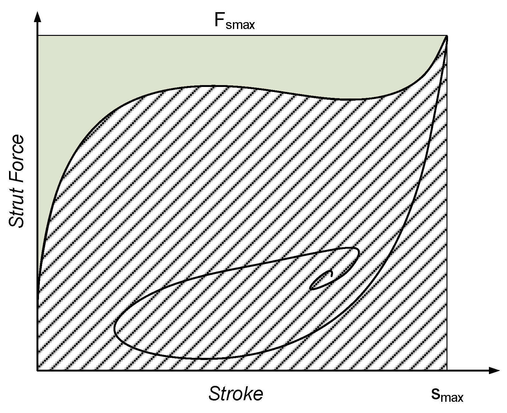
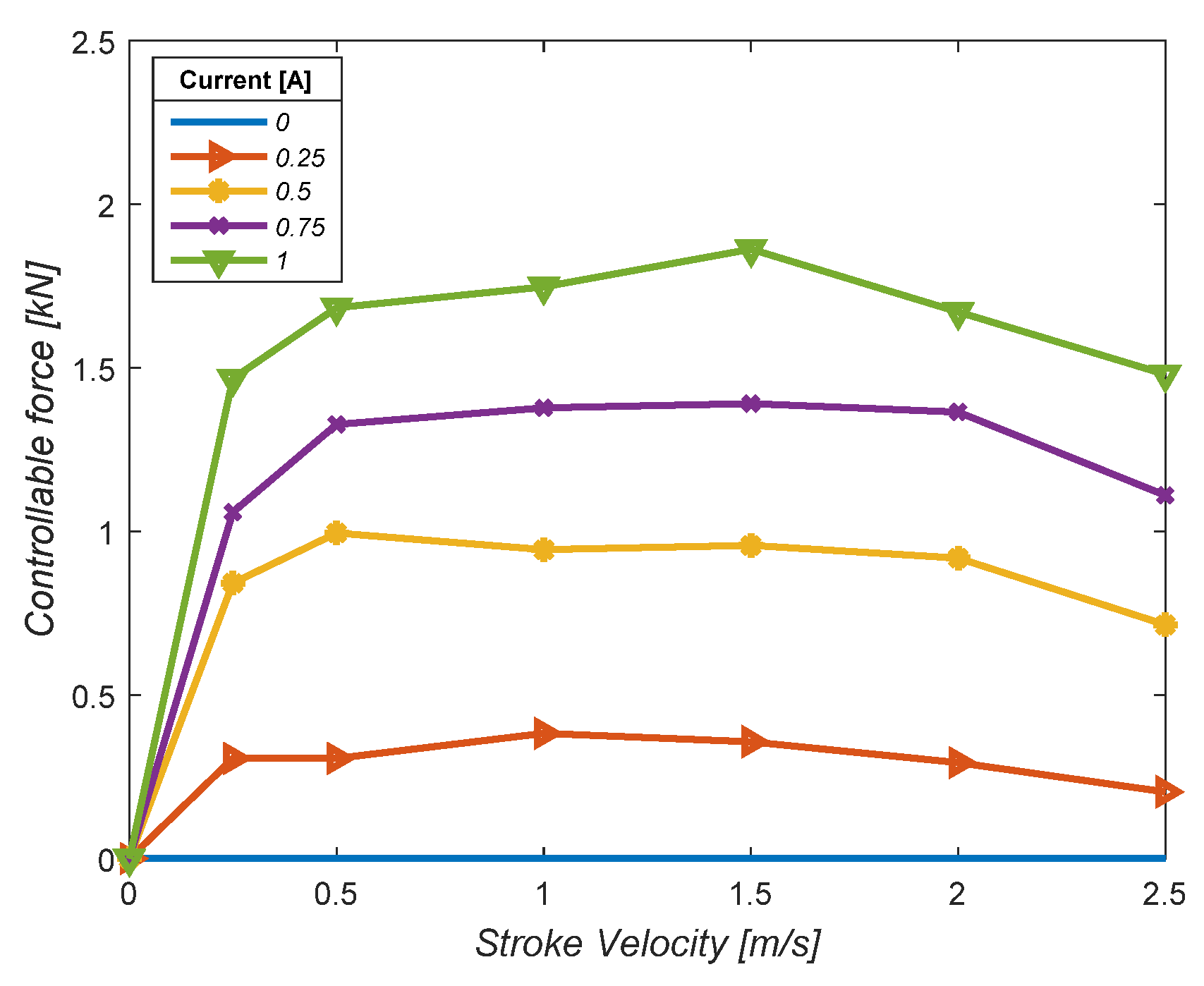
2.3. Controllable Force of the MR Damper

LORD MRF-140CG was used as the working fluid of the MR damper landing gear. This is an intelligent fluid, and the yield stress varies with the intensity of the external magnetic field. The magnitude of the controllable force generated through the internal flow passages can be investigated through experiments.
Semi-active control algorithms should use experimentally evaluated controllable forces with an applied current. The experiments on the MR damper controllable force characteristics were conducted by mounting the MR damper landing gear on a drop test jig and carrying out drop tests. The controllable force was measured by varying the current applied to the MR damper core from 0 A to 1 A at 0.25-A intervals. The results are shown in Figure 4. As more electrical current was applied, the control damping force increased, and when 1 A of current was applied, the maximum value of the MR force was measured at 1.7 kN.

3. Experiment Setup

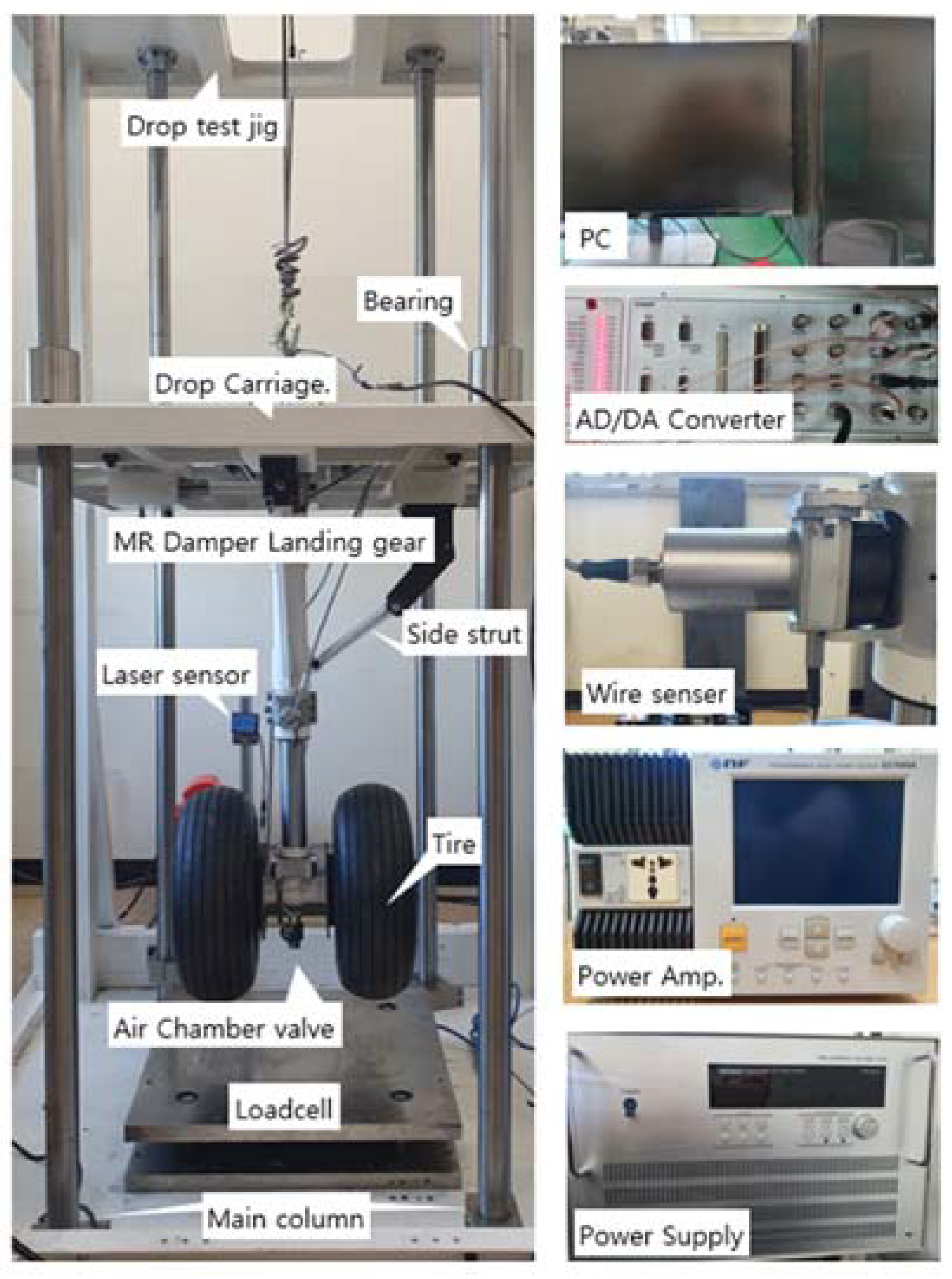
3.1. Test Jig and Components

The features of the MR damper landing gear covered in this study were based on the main landing gear structure of a Beechcraft Baron 55. The prototype fabricated and assembled for the performance test assessment is shown in Figure 5. The parameters of the designed MR damper landing gear are listed in Table 1. A side strut was connected to a cylinder and drop carriage to keep the cylinder in a position vertical to the ground, and a torsion link prevented the relative rotational motion of the cylinder and tire connector. The L-shaped tire connector created a large amount of friction force during the fall, which was caused by the normal force on the seals due to the ground reaction moment. Accordingly, a balanced T-shaped tire connector with two tires was combined with the piston to minimize this phenomenon. A ball valve was located at the bottom of the piston, allowing nitrogen gas to be injected into the air chamber. Figure 6 represents a drop test jig equipped with the MR damper landing gear and data acquisition system, including the sensors. A drop carriage capable of coupling dummy weights for various sprung mass conditions was fitted to the landing gear. On the ground, an electric hoist was employed to set various drop heights, using cables. The cable end of the electric hoist was attached to a drop carriage with a release device that could be manually disconnected. When the landing gear and drop carriage were raised to a height where the target sink speed could be acquired, the release device was operated, and the landing gear and drop carriage fall vertically as the four bearings moved along the main columns. The weight of the landing gear without tires was 15 kg, and it had a maximum compressible stroke of 220 mm. The drop test jig was designed to meet the drop test conditions specified in the Federal Aviation Regulations, Part 23.725 (FAR), when the drop height is 500 mm, measured at 3.1 m/s [33].

3.2. Data Acquisition and Control System

A multi-input-single-output control system was used for the MR damper landing gear constructed in this study. The displacement and acceleration of the sprung mass were measured using a laser displacement sensor installed on the ground (OD1000 SICK AG, Waldkirch, Germany) and an acceleration sensor (2220-010 SDI Inc., Kirkland, WA, USA). The stroke, which was the relative displacement of the cylinder and piston, was measured using a wire displacement sensor (SX50-250 WayCon GmbH, Brühl, Germany) connected to the cylinder and tire connector. The measured acceleration and stroke data were numerically integrated and differentiated, producing the sprung mass velocity and stroke velocity data. The sprung mass velocity and stroke velocity were fed into the semi-active controller, which was used to calculate the current applied to the MR damper core. The landing gear controller in this study used skyhook and hybrid control to calculate the output current, and it passed this signal to the power amplifier (EC750SA NF Corp., Kohoku-ku, Japan). The amplified output was transferred to the MR damper core within the landing gear, forming a magnetic field and producing a controllable force. The magnitude of the generated force was measured using pressure data obtained from two pressure sensors (TST-10 Tival Sensors GmbH, Wuppertal, Germany), one of which was connected to the upper chamber and the other to the lower chamber. The data acquisition device used a DS1104 board (dSPACE GmbH, Paderbom, Germany); the control system was implemented using the MATLAB/SIMULINK Real-Time Interface (RTI), and the sampling frequency of the control loop was set at 1 kHz. The compiler of the DS1104 board automatically created the designed controller algorithm as a file for use by the Control Desk software, making it very easy to configure a real-time control system without the need for additional programming.

4. Drop Experiment

To evaluate the performance of the MR damper landing gear, we performed drop tests. The drop test experiments in this study were focused on verifying the shock absorption performance of the landing gear. The sprung mass ( m 1 ) was set at 1/3 of the mass each landing gear was responsible for in the reference model (Baron 55). First, a drop test was conducted without control input to analyze the dynamic characteristics when the MR damper landing gear was operated passively. To determine the dynamic properties of the sprung mass, we set the drop height to 500 mm, increasing the weight of the drop carriage to 200, 230, and 245 kg. To determine the characteristics of the drop height, the weight of the drop carriage was fixed at 245 kg, and the drop height was set at 400 mm and 500 mm. To verify the performance of the control applied to the landing gear, we chose a sprung mass of 245 kg. The drop height was set at 500 mm to achieve the sink speed specified in Federal Aviation Regulation (FAR) 23.725. As control algorithms, skyhook and hybrid control were applied to the landing gear. The skyhook control algorithm is known to be effective in controlling attenuation forces in vehicle suspension systems. The control force calculated by the skyhook control is as follows.
F sky = C sky · z 1 ˙
where C sky is the control gain of the skyhook control algorithm, and z 1 ˙ is the vertical velocity of the sprung mass. Hybrid control is employed to compensate for the control gain setting, as skyhook control does not produce sufficient control damping force at low stroke velocity [25]. Hybrid control is a combination of skyhook control and force control [14]. The latter attempts to predict the force acting on the landing gear and generate the control force via the difference in the preset reference load. In hybrid control, skyhook control is applied during the entire interval in order to generate control damping forces. However, in low-velocity intervals, force control is further used to create appropriate control forces in order to maximize the efficiency of the shock absorption.
Figure 7 shows the flow diagram of the hybrid control algorithm and the conceptual diagram of the strut force –stroke curve. Hybrid control algorithms first applied skyhook control with the skyhook gain so that the first peak and second peak at the strut force--stroke diagram were at the same level. It then set the force at the first peak as the reference load ( F c o m ) and added a control damping force to match the difference between the reference load and the actual force, so as to act on the landing gear as the final control damping force. As a result, the shape on the strut force-stroke diagram was closer to a rectangle, demonstrating a higher shock absorption efficiency. Figure 8 represents a hybrid controller configured using MATLAB/SIMULINK RTI and the simulation model. The vertical velocity data for the sprung mass and stroke velocity data were input to the skyhook control algorithm, and the stroke data and stroke velocity data were input to the force control algorithm, as shown in Figure 8a. Depending on the experimental conditions, we applied a controller to the MR damper landing gear by selecting skyhook and hybrid control, respectively.
To compare the drop test results with the simulation results, we modeled the MR damper landing gear and the hybrid controller using SIMULINK Simscape, as shown in Figure 8b. When we applied the control method to the MR damper landing gear, there was a time delay before the control force fully acted due to the response time of the MR damper, which ranged from 20 to 30 ms. Because of this, the MR damper was assumed to be a first-order system. The initial conditions of the simulation were set to be the same as those of the drop test.

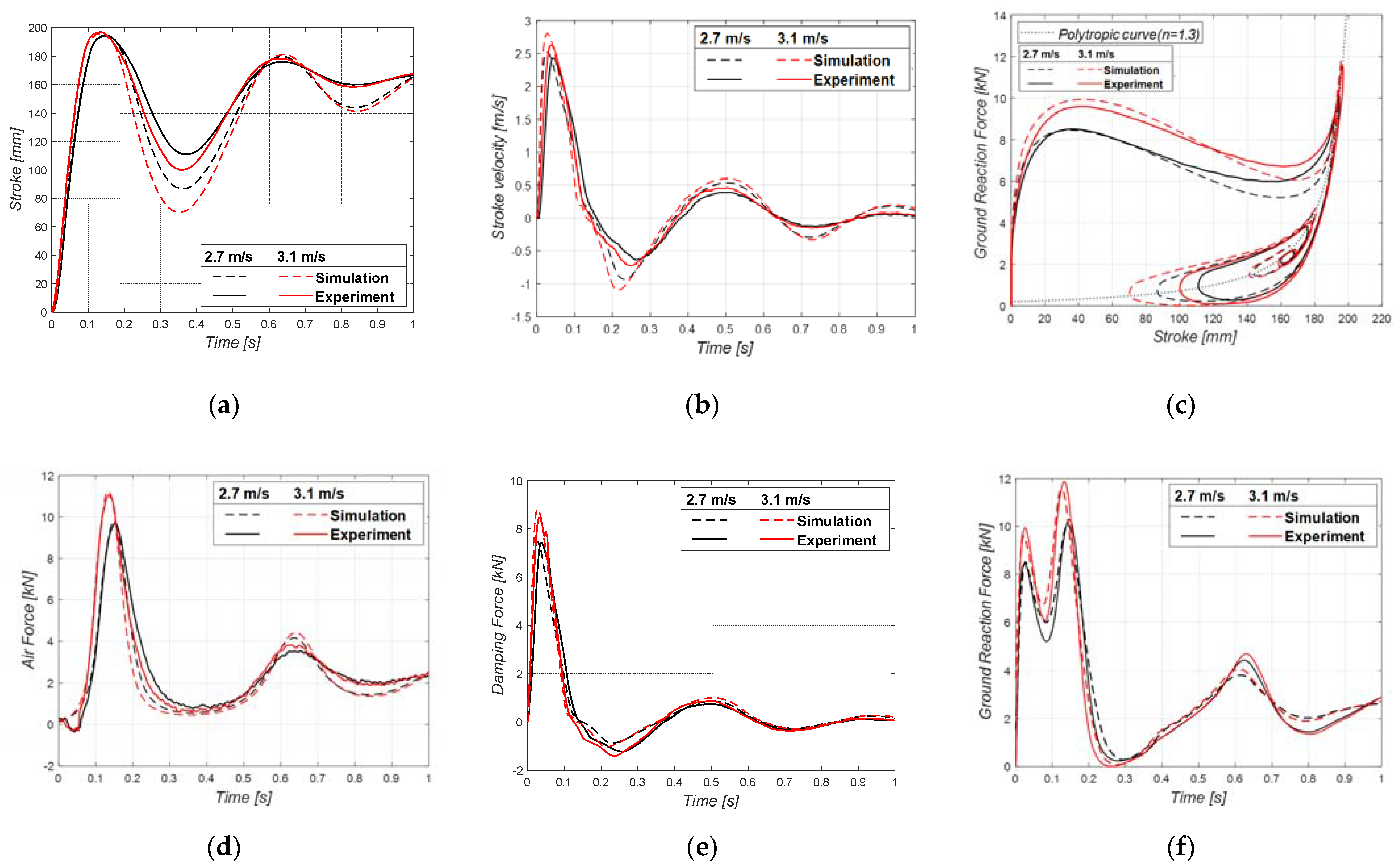
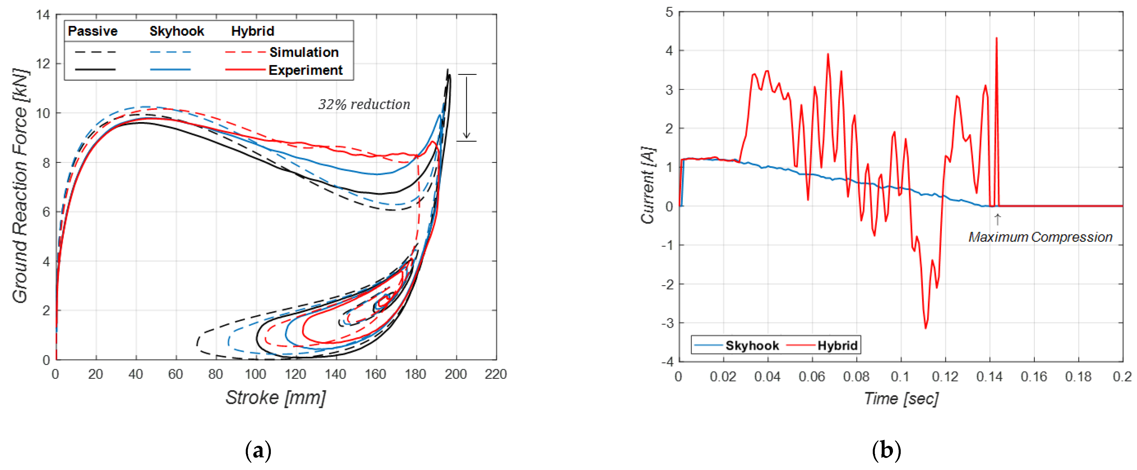
5. Experimental Results

The total internal force acting on the landing gear was too harsh to be accurately measured in the experiment. Therefore, in this study, the ground reaction force was used to investigate the landing characteristics. The results of the drop test for the MR damper landing gear covered in this study were as follows. First, at the same drop height of 500 mm, the stroke, the stroke velocity, the forces acting on the landing gear, and the ground reaction force–stroke diagrams of the drop tests for various sprung masses are shown in Figure 9. The solid and dashed lines represent the experimental and simulation results, respectively. The maximum compression stroke was shown to increase as the sprung mass increased, while the maximum stroke velocity demonstrated similar values. Because the landing gear fell from the same height, the vertical landing speed (i.e., the sink speed) was the same. At this point, the kinetic energy of the sprung mass, including the cylinder, was the energy that the landing gear was to absorb and dissipate and was proportional to the that of the sprung mass. The volume of the gas chamber sealed by the separator decreased as the stroke increased, and as the maximum compression stroke increased, the maximum gas pressure increased. The air force generated by the gas pressure converted the kinetic energy into potential energy in the compression process. Due to the pressure drop induced by the flow in the annular passage, the hydraulic force acting on the landing gear dissipated kinetic energy. Thus, the energy dissipated by the hydraulic damping force is shown to be similar in Figure 9e, and the potential energy absorbed by the air force increased with heavier sprung masses, as shown in Figure 9c,f. As the ground reaction force–stroke diagram shows, the first peak, which was determined by the maximum hydraulic force, reached similar levels in all cases. The second peak, which was determined by the maximum air force, increased as the sprung mass increased. The trend of this rise closely approximated that of the polytropic curve, indicating that the volume and pressure of the gas chamber conformed well to the polytropic law (n = 1.3). The changes in the two peaks were also be observed in the time series of the ground reaction force, and since this always had positive values, we inferred that the tires of the landing gear remained in contact with the ground.
Second, Figure 10 shows the drop test and simulation results performed by varying the drop height under the sprung mass of 245 kg. When the drop heights were 400 mm and 500 mm, the sink speeds were measured at 2.7 m/s and 3.1 m/s, respectively.
As the sink speed increased, the maximum values of both the stroke and the stroke velocity were shown to increase. Because the sprung mass was the same, the kinetic energy on landing was proportional to the square of the sink speed. Despite the increased maximum hydraulic force, which dissipated the kinetic energy, the maximum amount of air force also increased, meaning that the increase in kinetic energy due to the rise in the sink speed was greater than the increase in energy dissipated by the hydraulic force. With that difference, the energy absorbed by the gas chamber increased, resulting in an increase in the maximum air force. This was also confirmed by the ground reaction force–stroke diagram. Among the forces acting on the landing gear, the time taken for the hydraulic force to reach its maximum value was similar, but the time it took for the maximum air force to occur decreased as the vertical landing velocity increased. To simplify the mathematical modeling, the tire damping effect was ignored and only the pressure drop according to the shape of the flow passage was considered, particularly in the extension phase. This caused differences to emerge between the simulation and experimental results.
Next, a semi-active control algorithm was applied to perform a drop test and simulation. The results are shown in Figure 11. The ground reaction force–stroke diagram shows that the results of the simulations and experiments tended to be similar. When the MR damper landing gear was passive, the first peak was lower than the second peak. When the skyhook control algorithm created two peaks at similar levels in the diagram, it further dissipated energy via the control force generated. This reduced the maximum load acting on the landing gear and increased the efficiency of the shock absorption. The application of hybrid control with the first peak as the reference load created additional control forces that filled the dent between the two peaks. It also increased the amount of energy dissipated during the landing process. This can be seen from the diagram, in which the second peak is 32% lower than that in the passive landing gear. As with the results of the drop simulation, there was a delay in the operation of the MR damper until the control force was applied, indicating that the ground reaction force that did not work strictly on sprung mass did not act uniformly between the first and second peaks. The semi-active control algorithms for the MR damper were only applied during the first compression phase, i.e., 140 ms after landing, as shown in Figure 11b. The main results of the drop test using semi-active control algorithms are summarized in Table 2. When we applied the hybrid control algorithm, the maximum stroke was reduced by 5.7 mm compared to the passive type, and the efficiency of the shock absorption increased by 17.9% to 90.8%. Compared to the oleo-pneumatic damper, the complexity of the structure and weight of the MR damper did not increase significantly. Therefore, the MR damper landing system could extend the life of the aircraft by reducing the impact transmitted to the aircraft on the ground. In addition, when landing in an emergency, fuel jettison may be less likely if MR damper landing gear is used.

6. Conclusions

In this study, we experimentally validated the performance improvement of semi-active MR damper landing gear by fabricating an MR damper prototype and drop test jig and performing drop tests by applying a semi-active control algorithm (i.e., skyhook and hybrid control). First, we investigated the first and second peak changes on the ground reaction force–stroke diagram, depending on the sprung mass and sink speed when the MR damper landing gear operated passively, and we confirmed that the results of the drop test simulations and experiments tended to be the same. When the sprung mass changed, the maximum air force acting on the landing gear changed, resulting in a change in the second peak on the ground reaction force–stroke diagram. When the sink speed increases, the maximum value of the damper stroke velocity rose, which increased the hydraulic force at the beginning of compression. Furthermore, the increase in energy stored in the air chamber due to the rise in MR damper strokes can be seen on the ground reaction force–stroke diagram.
The skyhook and hybrid semi-active control algorithms were applied to the MR damper landing gear to conduct drop test experiments and simulations with a sprung mass of 245 kg and a sink speed of 3.1 m/s. When the skyhook control was applied to the MR damper landing gear, the two peak values in the diagram were set to the same level. When using hybrid control, the results of the drop test simulations and experiments confirmed that additional control force can be generated between the two peaks to maximize the performance of the shock absorption. The maximum load and maximum stroke acting on the MR damper landing gear was significantly reduced compared to the passive landing gear. The shock absorption efficiency of the landing gear improved by 17.9% over the passive operation. Under the design conditions, the passive oleo-pneumatic damper achieved high efficiency levels, up to 90%. However, under off-design conditions, the efficiency decreased rapidly. By employing the MR damper, it is possible to expand the range of landing conditions while maintaining high efficiency. Furthermore, we expect that reducing the delay in generating the MR damper control forces will enable us to maintain a constant strut force from the first peak to the second peak, thereby securing a better performance from MR damper landing gear.

Author Contributions

Data curation, B.-H.J. and D.-S.J.; formal analysis, B.-H.J. and D.-S.J.; investigation, D.-S.J.; methodology, D.-S.J. and J.-H.H.; project administration, J.-H.H.; software, B.-H.J. and Y.-H.C.; supervision, D.-S.J. and J.-H.H.; writing—original draft, B.-H.J.; writing—review and editing, D.-S.J. and J.-H.H. All authors have read and agreed to the published version of the manuscript.

Funding

This work was funded by the Ministry of Trade, Industry & Energy (MOTIE, Korea), grant number 10073291.

Institutional Review Board Statement

Not applicable.

Informed Consent Statement

Not applicable.

Data Availability Statement

Not applicable.

Acknowledgments

This work was supported by the Technology Innovation Program (intelligent landing gear with variable damping force for 1500lb class) (10073291).

Conflicts of Interest

The authors declare no conflict of interest.

References

  1. McGehee, J.R.; Carden, H.D. Analytical Investigation of the Landing Dynamics of a Large Airplane with a Load-Control System in the Main Landing Gear; NASA: Washington, DC, USA, 1979; p. 86. [Google Scholar]
  2. Milwitzky, B.; Cook, F.E. Analysis of Landing-Gear Behavior; National Advisory Committee for Aeronautics: Washington, DC, USA, 1953; p. 51. [Google Scholar]
  3. Tourajizadeh, H.; Zare, S. Robust and Optimal Control of Shimmy Vibration in Aircraft Nose Landing Gear. Aerosp. Sci. Technol. 2016, 50, 1–14. [Google Scholar] [CrossRef]
  4. Somieski, G. Shimmy Analysis of a Simple Aircraft Nose Landing Gear Model Using Different Mathematical Methods. Aerosp. Sci. Technol. 1997, 1, 545–555. [Google Scholar] [CrossRef]
  5. Currey, N.S. Aircraft Landing Gear Design: Principles and Practices; American Institute of Aeronautics and Astronautics: Washington, DC, USA, 1988; ISBN 978-0-930403-41-6. [Google Scholar]
  6. Wu, D.; Gu, H.; Liu, H. GA-Based Model Predictive Control of Semi-Active Landing Gear. Chin. J. Aeronaut. 2007, 20, 47–54. [Google Scholar] [CrossRef] [Green Version]
  7. Karnopp, D.; Crosby, M.J.; Harwood, R.A. Vibration Control Using Semi-Active Force Generators. J. Eng. Ind. 1974, 96, 619–626. [Google Scholar] [CrossRef]
  8. Wang, X.; Carl, U. Fuzzy Control of Aircraft Semi-Active Landing Gear System. In Proceedings of the 37th Aerospace Sciences Meeting and Exhibit, Reno, NV, USA, 11–14 January 1999. [Google Scholar]
  9. Wolf, K. Integrated Design Process for the Development of Semi-Active Landing Gears for Transport Aircraft. Ph.D. Dissertation, Institut für Flugmechanik und Flugregelung der Universität Stuttgart, Stuttgart, Germany, 2000. [Google Scholar]
  10. Choi, Y.-T. Vibration Control of a Landing Gear System Featuring Electrorheological/Magnetorheological Fluids. J. Aircr. 2003, 40, 432–439. [Google Scholar] [CrossRef]
  11. Khani, M.; Stiharu, I.; Sedaghati, R. Magneto-Rheological (MR) Damper for Landing Gear System. In Proceedings of the AIAA Modeling and Simulation Technologies Conference, Chicago, IL, USA, 10–13 August 2009. [Google Scholar]
  12. Han, C.-H.; Kim, B.-G.; Choi, S.-B. Design of a New Magnetorheological Damper Based on Passive Oleo-Pneumatic Landing Gear. J. Aircr. 2018, 55, 2510–2520. [Google Scholar] [CrossRef]
  13. Han, C.-H.; Kang, B.-H.; Choi, S.-B.; Tak, J.-M.; Hwang, J.-H. Control of Landing Efficiency of an Aircraft Landing Gear System with Magnetorheological Dampers. J. Aircr. 2019, 56, 1980–1986. [Google Scholar] [CrossRef]
  14. Hyun, Y.-O. Semi-Active Force Control of Landing Gear Using Magneto-Rheological Damper. Ph.D. Thesis, Korea Aerospace University, Goyang-si, Korea, 2009. [Google Scholar]
  15. Ahuré-Powell, L.A. Magnetorheological Fluids and Applications to Adaptive Landing Gear for a Lightweight Helicopter. Ph.D. Thesis, University of Maryland, College Park, MD, USA, 2014. [Google Scholar]
  16. Choi, Y.-T.; Robinson, R.; Hu, W.; Wereley, N.M.; Birchette, T.S.; Bolukbasi, A.O.; Woodhouse, J. Analysis and Control of a Magnetorheological Landing Gear System for a Helicopter. J. Am. Helicopter Soc. 2016, 61, 1–8. [Google Scholar] [CrossRef]
  17. Joe, B.-H.; Jang, D.-S.; Hwang, J.-H. Internal Components Arrangement of MR Damper Landing Gear for Cavitation Prevention. J. Aerosp. Syst. Eng. 2020, 14, 33–41. [Google Scholar] [CrossRef]
  18. Ashour, O.; Rogers, C.A.; Kordonsky, W. Magneto-Rheological Fluids_Materials, Characterization, and Devices. J. Intell. Mater. Syst. Struct. 1996, 7, 123–130. [Google Scholar] [CrossRef]
  19. Carlson, J.D.; Catanzarite, D.M.; Clair, K.A.S. Commercial Magneto-Rheological Fluid Devices. Int. J. Mod. Phys. B 1996, 10, 2857–2865. [Google Scholar] [CrossRef]
  20. Yao, G.Z.; Yap, F.F.; Chen, G.; Li, W.H.; Yeo, S.H. MR Damper and Its Application for Semi-Active Control of Vehicle Suspension System. Mechatronics 2002, 12, 963–973. [Google Scholar] [CrossRef] [Green Version]
  21. Gu, Z.Q.; Oyadiji, S.O. Application of MR Damper in Structural Control Using ANFIS Method. Comput. Struct. 2008, 86, 427–436. [Google Scholar] [CrossRef]
  22. Batterbee, D.C.; Sims, N.D.; Stanway, R.; Wolejsza, Z. Magnetorheological Landing Gear: 1. A Design Methodology. Smart Mater. Struct. 2007, 16, 2429–2440. [Google Scholar] [CrossRef] [Green Version]
  23. Lee, H.-S.; Jang, D.-S.; Hwang, J.-H. Modeling of MR Damper Landing Gear Considering Incompletely Developed Fluid Flow. J. Aerosp. Syst. Eng. 2021, 15, 7–18. [Google Scholar] [CrossRef]
  24. Kim, T.-U.; Lee, S.-W.; Shin, J.-W.; Lee, S.-K.; Kim, S.-C.; Hwang, I.-H.; Kang, S.-H. Drop Test of an Oleo-pneumatic Landing Gear. J. Korean Soc. Aeronaut. Space Sci. 2010, 38, 1130–1135. [Google Scholar] [CrossRef]
  25. Batterbee, D.C.; Sims, N.D.; Stanway, R.; Rennison, M. Magnetorheological Landing Gear: 2. Validation Using Experimental Data. Smart Mater. Struct. 2007, 16, 2441–2452. [Google Scholar] [CrossRef]
  26. Lee, D.-Y.; Nam, Y.-J.; Yamane, R.; Park, M.-K. Performance Evaluation on Vibration Control of MR Landing Gear. J. Phys. Conf. Ser. 2009, 149, 012068. [Google Scholar] [CrossRef]
  27. Hwang, J.-U.; Hwang, J.-H.; Bae, J.-S.; Lim, K.-H. Drop Test Simulation of Semi-active Landing Gear using Commercial Magneto-Rheological Damper. J. Aerosp. Syst. Eng. 2010, 4, 44–48. [Google Scholar]
  28. Hyun, Y.-O.; Hwang, J.-U.; Hwang, J.-H.; Bae, J.-S.; Lim, K.-H.; Kim, D.-M.; Kim, T.-W.; Park, M.-H. Force Control of Main Landing Gear using Magneto-Rheological Damper. J. Korean Soc. Aeronaut. Space Sci. 2009, 37, 344–349. [Google Scholar] [CrossRef]
  29. Tak, J.-M.; Viet, L.Q.; Hwang, J.-H. Hybrid Control of Aircraft Landing Gear using Magnetorheological Damper. J. Aerosp. Syst. Eng. 2018, 12, 1–9. [Google Scholar] [CrossRef]
  30. Viet, L.Q.; Lee, H.-S.; Jang, D.-S.; Hwang, J.-H. Sliding Mode Control for an Intelligent Landing Gear Equipped with Magnetorheological Damper. J. Aerosp. Syst. Eng. 2020, 14, 20–27. [Google Scholar] [CrossRef]
  31. Viet, L.Q.; Jang, D.-S.; Hwang, J.-H. Robust Adaptive Control for an Aircraft Landing Gear Equipped with a Magnetorheological Damper. Appl. Sci. 2020, 10, 1459. [Google Scholar] [CrossRef] [Green Version]
  32. Viet, L.Q.; Jang, D.-S.; Hwang, J.-H. Intelligent Control Based on a Neural Network for Aircraft Landing Gear with a Magnetorheological Damper in Different Landing Scenarios. Appl. Sci. 2020, 10, 5962. [Google Scholar] [CrossRef]
  33. Federal Aviation Administration. FAR Sec.23.725 Limit Drop Tests. Available online: https://www.risingup.com/fars/info/part23-725-FAR.shtml (accessed on 17 August 2021).
  34. Hwang, J.-H. Aerospace Parts Technology Development Project: Intelligent Landing Gear with Variable Damping Force for 1500 Ib Class; Korea Evaluation Insititute of Industrial Technology: Daegu, Korea, 2020.
Figure 1. Landing gear equipped with an MR damper.
Aerospace 08 00272 g001
Figure 2. Modeling the landing gear equipped with the MR damper.
Aerospace 08 00272 g002
Figure 3. Strut force-stroke diagram.
Aerospace 08 00272 g003
Figure 4. Stroke velocity vs. controllable force, according to applied current.
Aerospace 08 00272 g004
Figure 5. MR damper landing gear [34].
Aerospace 08 00272 g005
Figure 6. Experimental setup.
Aerospace 08 00272 g006
Figure 7. Hybrid control: (a) Flow diagram; (b) Conceptual diagram of the strut force-stroke curve.
Aerospace 08 00272 g007
Figure 8. MATLAB/Simulink diagram: (a) Hybrid controller with dSPACE; (b) Simulation model using Simpscape.
Aerospace 08 00272 g008
Figure 9. Drop test results for various sprung masses (200 kg, 230 kg, 245 kg), with a sink speed of 3.1 m/s; (a) Stroke; (b) Stroke velocity; (c) Ground reaction force for stroke diagram; (d) Air force; (e) Hydraulic force; (f) Ground reaction force.
Aerospace 08 00272 g009aAerospace 08 00272 g009b
Figure 10. Drop test results for various sink speeds (2.7 m/s, 3.1 m/s), with a sprung mass of 245 kg: (a) Stroke; (b) Stroke velocity; (c) Ground reaction force for stroke diagram; (d) Air force; (e) Hydraulic force; (f) Ground reaction force.
Aerospace 08 00272 g010
Figure 11. Drop test results for control algorithm (sink speed = 3.1 m/s, sprung mass = 245 kg): (a) Ground reaction force for stroke diagram; (b) Control input, current.
Aerospace 08 00272 g011
Table 1. Parameters of the MR damper landing gear.
ParameterValue
Total weight of the MR damper, W 15   kg
Maximum compressible stroke, S m a x 0.22   m
Piston area, including the outer wall, A a 2.018 × 10 3   m 2
Piston area, excluding the outer wall, A p 2.551 × 10 3   m 2
Gap sizes of the annular passages, t 1 , t 2 2.1 × 10 3   m ,   2.4 × 10 3   m
Center radii of the annular passages, R 1 , R 2 21.87 × 10 3   m ,   27.3 × 10 3   m
Fluid density, ρ 3540 3740   kg / m 3
Fluid viscosity, η   @ 40 ° C 0.28 ± 0.07   Pa · s
Maximum yield stress, τ y , m a x 58   kPa
Number of turns, N 900
AWG of the wire 27
Table 2. Drop test results.
TypeMax. StrokeMax. Strut ForceEfficiency
(Experiment)
Efficiency
(Simulation)
Passive196.9 mm11.6 kN72.9%73.5%
Skyhook192.1 mm9.8 kN87.6%82.4%
Hybrid191.2 mm9.8 kN90.8%90.2%
Publisher’s Note: MDPI stays neutral with regard to jurisdictional claims in published maps and institutional affiliations.

