1. Introduction
Homogeneous and efficient fire suppression agent distribution inside an aircraft cargo hold is the key for protecting the aircraft from a cargo hold fire and for achieving the fire protection goals. Aircraft cargo with fire suppression systems must provide fire protection for several hours. Thus, the system must be adequate to maintain a safe fire suppressive atmosphere inside the cargo hold for the specified diversion time.
The aircraft cargo fire suppression system has two major phases, a knockdown phase that diminishes fire either by cooling the fire or reducing the oxygen concentration as described in the Minimum Performance Standard (MPS) [
1], followed by the holding phase to maintain a fire suppressive environment inside the cargo hold throughout the flight and landing phase. The main design parameters for the system sizing are the cargo hold volume, the agent target concentration, and the air tightness. For example, the cargo door seal is subjected to the gradient between the pressurized fuselage and ambient conditions at cruising and thus leaks air. This air is replaced with fresh air aspired through the Pressure Management System (PMS) to ensure the balance of airflows. A controlled supply of additional agent to compensate for the air ingress is thus necessary during the holding phase. Additionally, the PMS prevents pressure peaks during agent injection that would lead to opening of the rapid decompression panels by allowing air to leave the cargo hold.
Today, a large quantity of halon from bottles is released to perform the knockdown within two minutes, and then the fire suppressive environment is maintained within the cargo hold by constant metering of halon. However, due to high Ozone Depletion Potential (ODP) of halon, the aerospace industry is looking for halon-free systems. The use of nitrogen as a suppression agent, diluting the cargo hold oxygen concentration below the flammability point, is one such alternative under research within the CleanSky2 “Environmentally Friendly Fire Protection” (EFFP) project. Within this project, a simulation toolchain is developed that predicts the agent concentration distribution within the cargo hold, and a physical full-scale demonstration is implemented in the Flight Test Facility, a low-pressure chamber hosting the front section of a former in-service A310 including the underfloor area and forward cargo hold.
This paper presents transient validation results of a nitrogen knockdown followed by a holding phase and descent.
Several modelling activities have been performed for halon replacement technology with water mist, inert gases, and solid-propellant gas-generator suppression systems [
2,
3,
4,
5]. These models include CFD simulations and single or two-zone models. However, these models simulate agent distribution at constant pressure, single operating points or are non-locally refined. In cargo fire suppression systems, the transient phases of knockdown, holding, and descent have significant impacts on the agent distribution inside the cargo hold. The location of air ingress ports, such as the pressure management system (PMS,
Section 2.2.1), or leakages in the cargo interiors, further influences the local agent distribution gradient in the cargo hold.
Single or two-zone models are quick to run; however, these models do not provide a local agent distribution inside the cargo hold. CFD models provide the details of agent distribution, but the computation cost is very high, especially when transient phases are considered. The IESS uses a hybrid simulation approach, where the high momentum flow regime close to the discharge nozzle has been pre-simulated by CFD, and the results of this near-field domain have been integrated in a zonal model of the cargo hold.
In this paper, a validation result for such a transient simulation is shown. For this, a nitrogen-based knockdown and holding system has been integrated in the Flight Test Facility aircraft mock-up. The cargo hold has been equipped with sensors to measure the local oxygen concentration. A realistic cabin pressure profile of take-off, cruising, and descent is implemented using a low-pressure vessel, which is able to generate an ambient pressure similar to cruising conditions (750 hPa, corresponding to an equivalent height of 8.000 ft.).
2. Materials and Methods
In this study, both numerical modelling and experimental testing are used. The following sections describe the simulation method applied with the Indoor Environment Simulation Suite (IESS,
Section 2.1), as well as the experimental method (
Section 2.2) in the Flight Test Facility (FTF).
2.1. Indoor Environment Simulation Suite (IESS)
The Indoor Environment Simulation Suite (IESS,
Figure 1) provides indoor climatic simulations using the zonal approach. In contrast to CFD or multi-zone models, the zonal modelling approach subdivides the indoor space into typically 10² to 10³ zones. In addition to this airflow modelling, the IESS provides interfaces for walls, sources and sinks, radiation, conduction, and species distribution. Through this, a transient, multiphysics simulation is enabled. A toolchain has been developed to ease the setup, customization, and post-processing of the models.
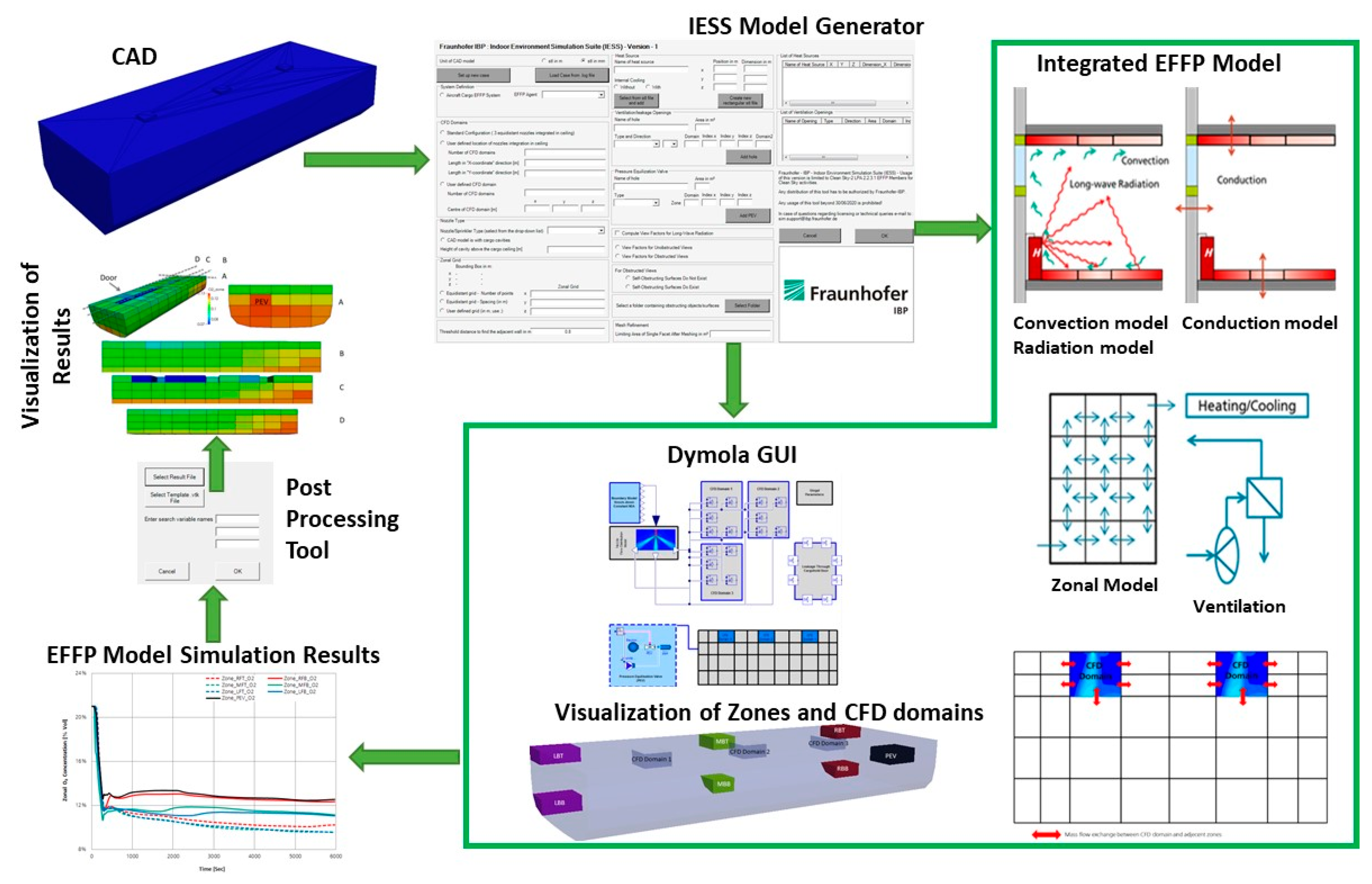
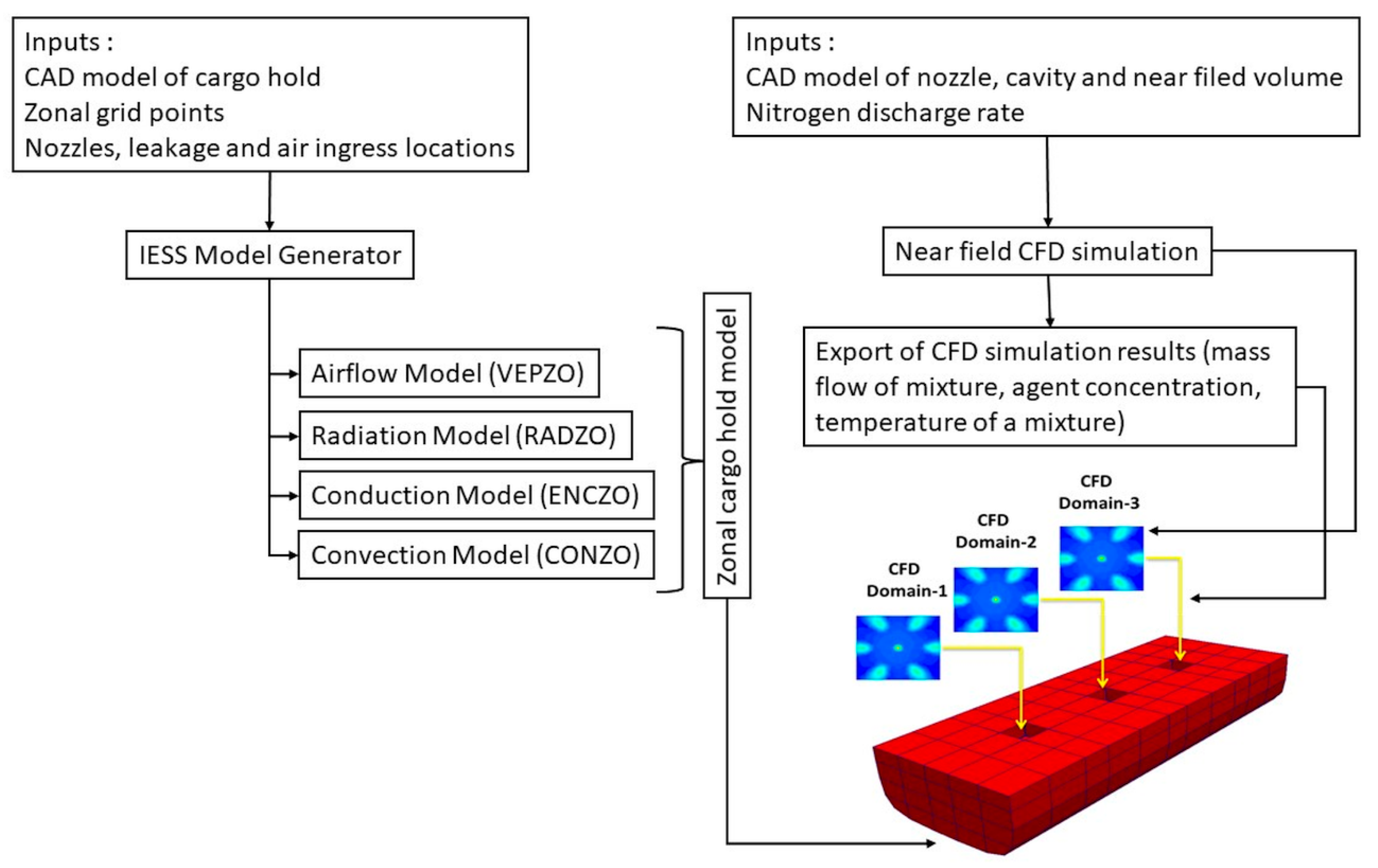
Figure 1 shows a typical modelling workflow. Starting from a CAD geometry of the space envelope, the IESS Model Generator exports a Modelica model with zonal subdivision. This integrated model contains the following major submodels:
Zonally subdivided air volume model;
Models of ventilation sinks and sources;
Zonally subdivided wall facet models including conduction in the material, convective heat exchange with adjacent air volumes, and radiative heat exchange with other surfaces;
Interfaces to integrate boundary conditions that are pre-simulated by CFD.
A rudimentary graphical user interface for setting the boundary conditions is produced along with a visualization of the zones’ distribution. After the simulation, results are displayed as transient plots, and a post processing tool generates 3D visualizations of scalar quantities, such as temperature or concentrations in the zones. In the following sections, each of these bricks is described in further detail.
2.1.1. IESS Model Generator
The IESS Model Generator is a pre-processing tool developed in C++. It translates a CAD model exported into the .stl format to Modelica code that can be simulated in the Modelica simulation environment [
6]. This tool automatically distributes the zonal grid, attributes the adjacencies of zones and walls and provides top-level parameters such as source intensities, exterior temperature, etc., for easy model customization.
2.1.2. Airflow Model (VEPZO)
The aim of a zonal model is to perform quick simulations of the airflow pattern and temperature distribution in an indoor space. Therefore, an air volume is subdivided into several discrete zones. Zonal models are a compromise between the more complex CFD calculations and the approximation of a perfectly mixed air volume as assumed by single node models. A new formulation of such models has been developed by Fraunhofer IBP, the VElocity Propagating Zonal model (VEPZO model). The VEPZO model uses the airflow velocity as a property of a zone and a viscous loss model in order to better match the physics of airflows. The two main components of the VEPZO model are a volume model and a flow model. The volume model considers mass conservation and conservation of enthalpy while the flow model calculates the mass flow rate from the pressure difference. The advantages of the VEPZO model are as follows: only a limited amount of information on the boundary conditions is necessary, in addition to the delivery of a local resolution of air temperatures, agent concentrations, and air flow within a domain as well as a moderate computational cost, which finally allows parametric variation for transient situations [
7]. Zones are coupled to the CFD domain by exchanging mass flow at the boundary, to walls by convective heat exchange, and to other sources and sinks such as leakage flows, internal heat sources, etc.
The cargo hold model has been subdivided into 11 × 5 × 4 zones. Three CFD domains (cf.
Section 2.1.6) provide inlet conditions for the agent injection. Leakage through the cargo door (cf.
Section 2.2.1) is represented by a sink. The pressure management system (PMS, cf.
Section 2.2.1) is implemented as a two-way flow model to ensure that the overall balance of airflow sums to zero and to avoid pressure peaks in the simulation.
Wall facets are distributed according to the zonal decomposition and exchange heat with the adjacent zones by convection.
2.1.3. Longwave Radiation Model Coupled with Zonal Model (RADZO)
Especially in applications with increased temperature differences between surfaces, the longwave radiation generates an important heat flow and thus impacts surface temperatures. The radiation model coupled with the zonal model (RADZO) computes view factors between finely refined surface mesh elements and allocates accurate view factors to the course zonal grid mesh. The RADZO model calculates longwave radiant heat exchange between all “n” surfaces [
8]. The accurate estimation of surface temperatures leads to a more accurate prediction of air temperature stratification and thus airflow pattern and agent distribution.
2.1.4. Conduction through the Enclosure Model (ENCZO)
Enclosure models are based on a suite of thermal capacitances and thermal resistances. Different materials are implemented in the model by adjusting these characteristic parameters. The enclosure can be simulated as a single or multiple layer model. The Model Generator exports a template wall model in the initial code that is later customized to the actual wall layers by the modeler. In the application presented here, conduction through honeycomb panels is implemented.
2.1.5. Convection Model Coupled with the Zonal Model (CONZO)
Since the boundary layer flow is not resolved in the zonal model, the numerical determination of the convective heat transfer coefficient
hc is not possible. This depends on the orientation of the surfaces, the temperature difference relative to the air, and the prevailing flow conditions. The IESS-CONZO library therefore provides a collection of correlations for various situations and predicts the
hc value based on the local air exchange in a zone [
9].
2.1.6. CFD Domain
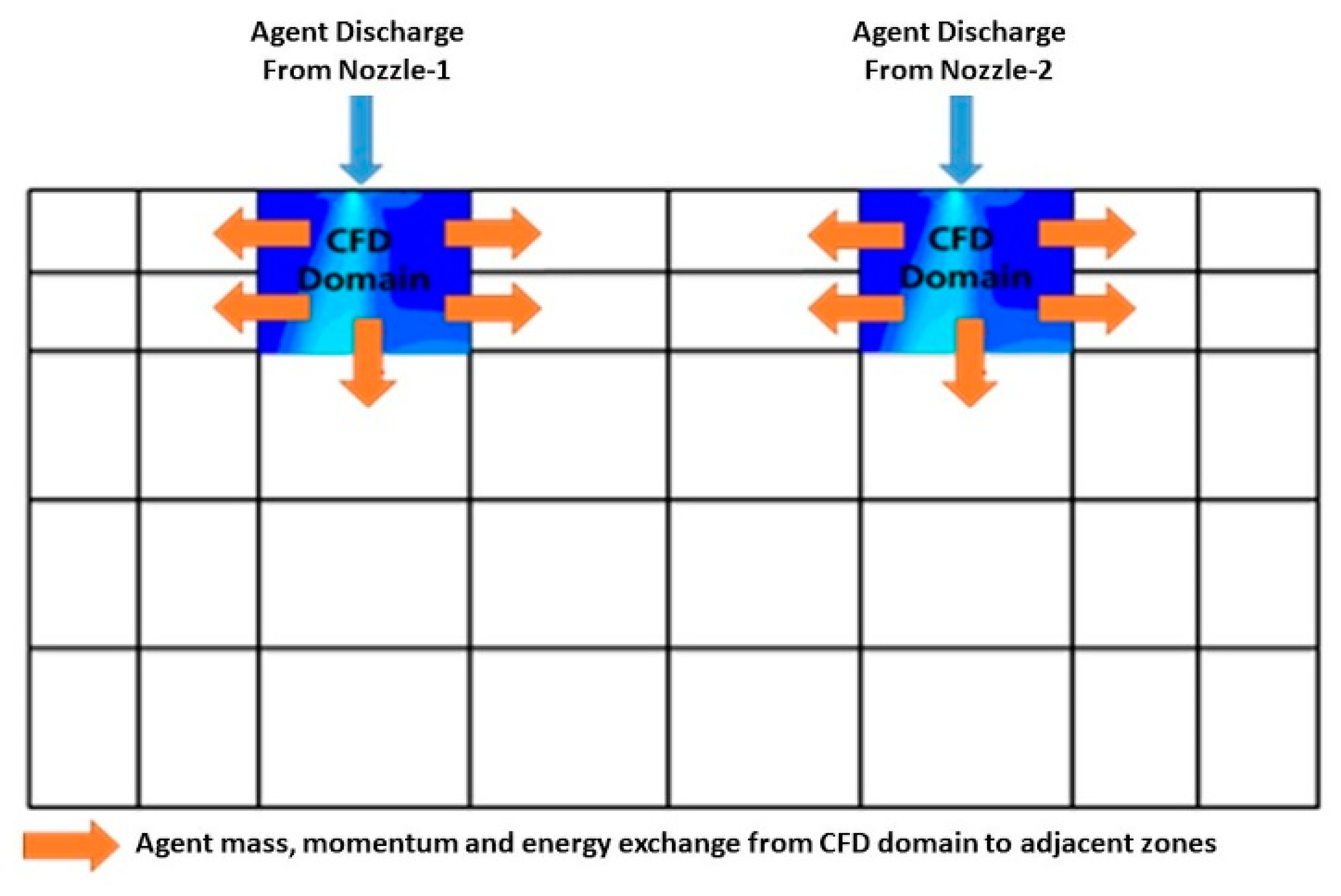
The CFD domain was specifically developed for increasing the accuracy of the zonal modelling approach for the cargo fire suppression application. The inert agent typically is provided from pressurized bottles and is distributed through nozzles in the ceiling of the cargo hold. This results in a local high momentum flow pattern around the inlet nozzle. The scale of this flow is far smaller than the typical size of a zone, but it determines the flow field in the entire compartment. In order to maintain the high simulation speed possible with the zonal modelling approach, the concept of a CFD zone has been selected. In this approach, the nearfield around the injection nozzle is pre-simulated by CFD. Due to the small size of this domain, the CFD computation converges relatively quickly. The simulation result is used as a supply/sink boundary condition in the zonal model in order to transmit the effect of the nozzle to the large space of the cargo hold.
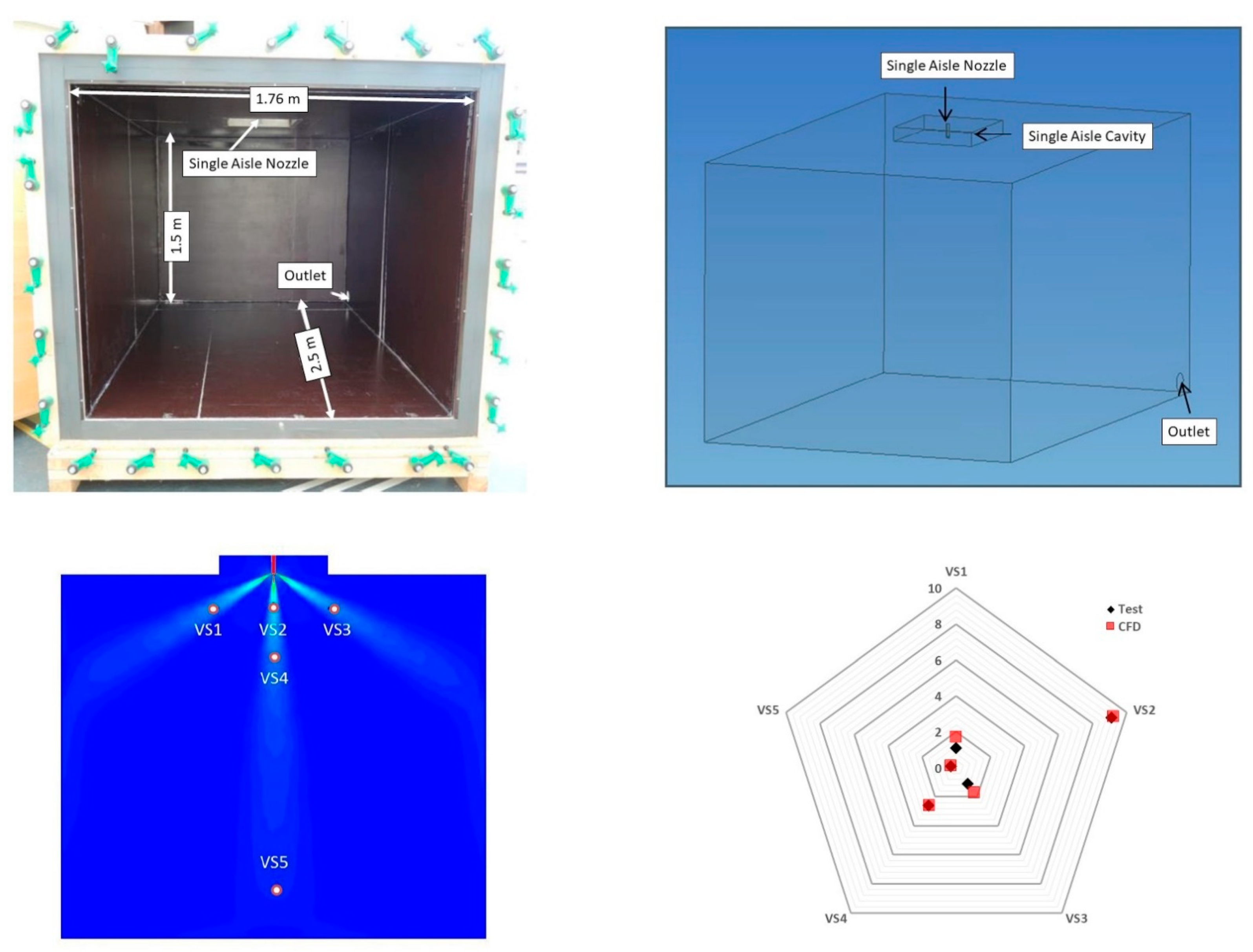
To numerically solve the high momentum flow and turbulent eddies in the vicinity of the agent discharge, the CFD simulation of the Airbus single aisle nozzle and the A350 nozzle was performed prior to setting up the cargo hold zonal model.
In order to verify the general approach, these CFD simulations were validated by tests on a small prototype single nozzle-cavity demonstrator (
Figure 2, top). The nozzle was connected to a nitrogen cylinder, and flow rates and pressure were controlled. Anemometers were placed in the nozzle jet regions, and readings were compared to the CFD calculation (
Figure 2, bottom).
The decline of the flow velocity below 2 m/s was used as a criterion to generate a box around the CFD domain (
Figure 3). The mass flow across the surfaces of this box, the average temperature, and concentration are provided as tabulated boundary conditions for the zonal model of the cargo hold.
2.1.7. Integrated Cargo Hold Model
Figure 4 summarizes the workflow used to generate the model of the A310 forward cargo hold. From the geometrical definition of the cargo hold setup, the IESS Model Generator automatically creates the zonal Airflow, Radiation, Conduction, and Convection models. The pre-simulated near-field CFD model of the injection nozzle is integrated in three positions as boundary conditions for mass flow and supply temperature/concentrations. Each of the blocks represents a volume that is further connected to flow models, leakage models or convection models depending on the location in the cargo hold. The pressure management system (PMS) model is connected to the aft wall of the cargo hold.
This model has been used for parametric studies for different discharge profiles, different descent profiles, and different fire suppression strategies [
10] and is now validated with experiments.
2.2. Test Setup
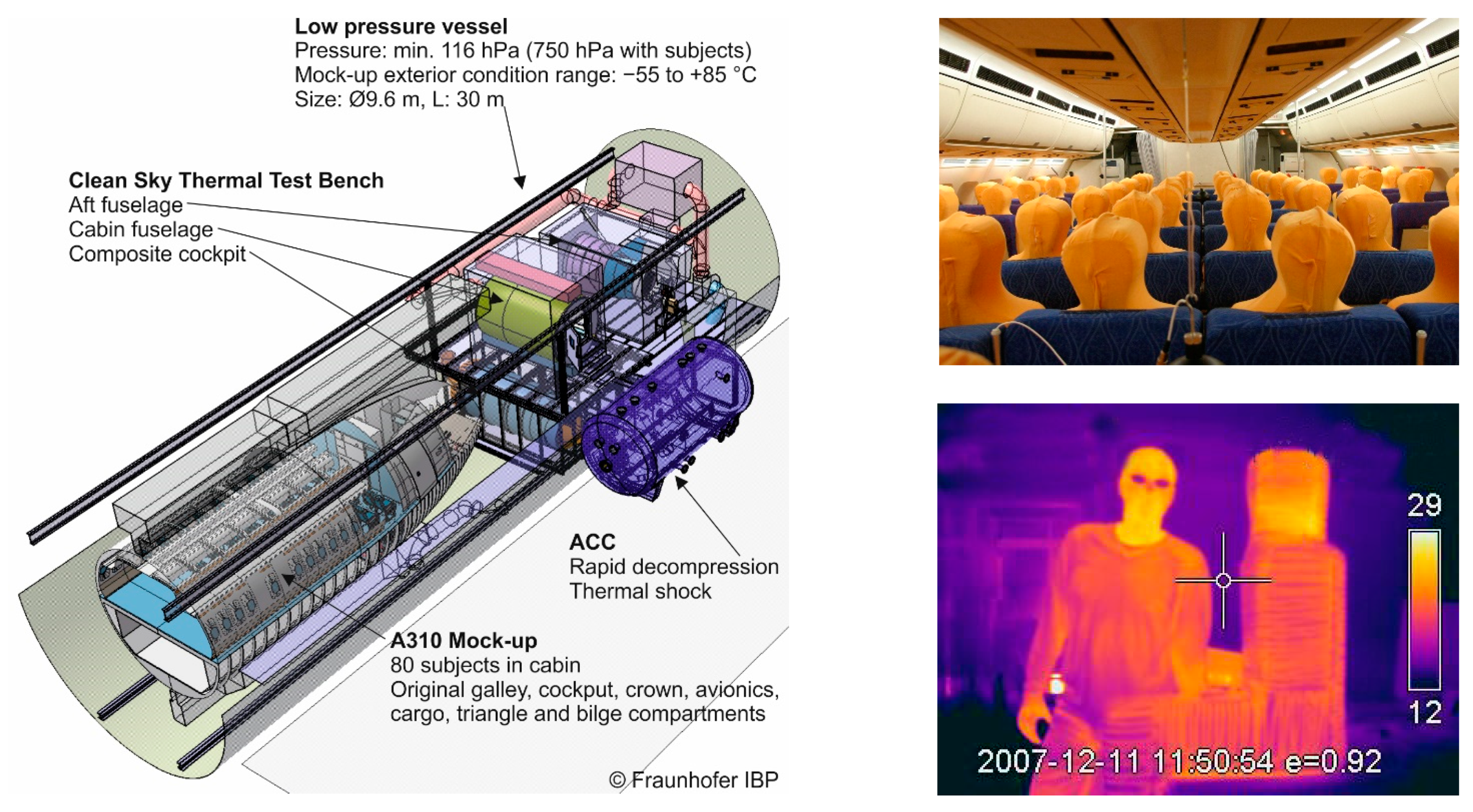
Experiments were conducted in the A310 mock-up of the Flight Test Facility (FTF) located at the Fraunhofer-Institute for Building Physics in Holzkirchen, Germany. A schematic view of the FTF is presented in
Figure 5. The front part of a former in-service twin-aisle long range aircraft containing a cabin, crown, galley, cockpit, avionics bay, cargo, and bilge was placed in a low-pressure vessel. Through the variation of the pressure in the vessel, the cabin pressure evolution of a real flight can be simulated. The mock-up is equipped with a ventilation system to replicate the environmental control system (ECS). In order to generate a similar heat load in the cabin, thermal dummies were placed on the seats. Through this, a realistic airflow pattern in the cabin was ensured. Recirculation air was aspired from the triangular area, and exhaust air was ejected from the bilge.
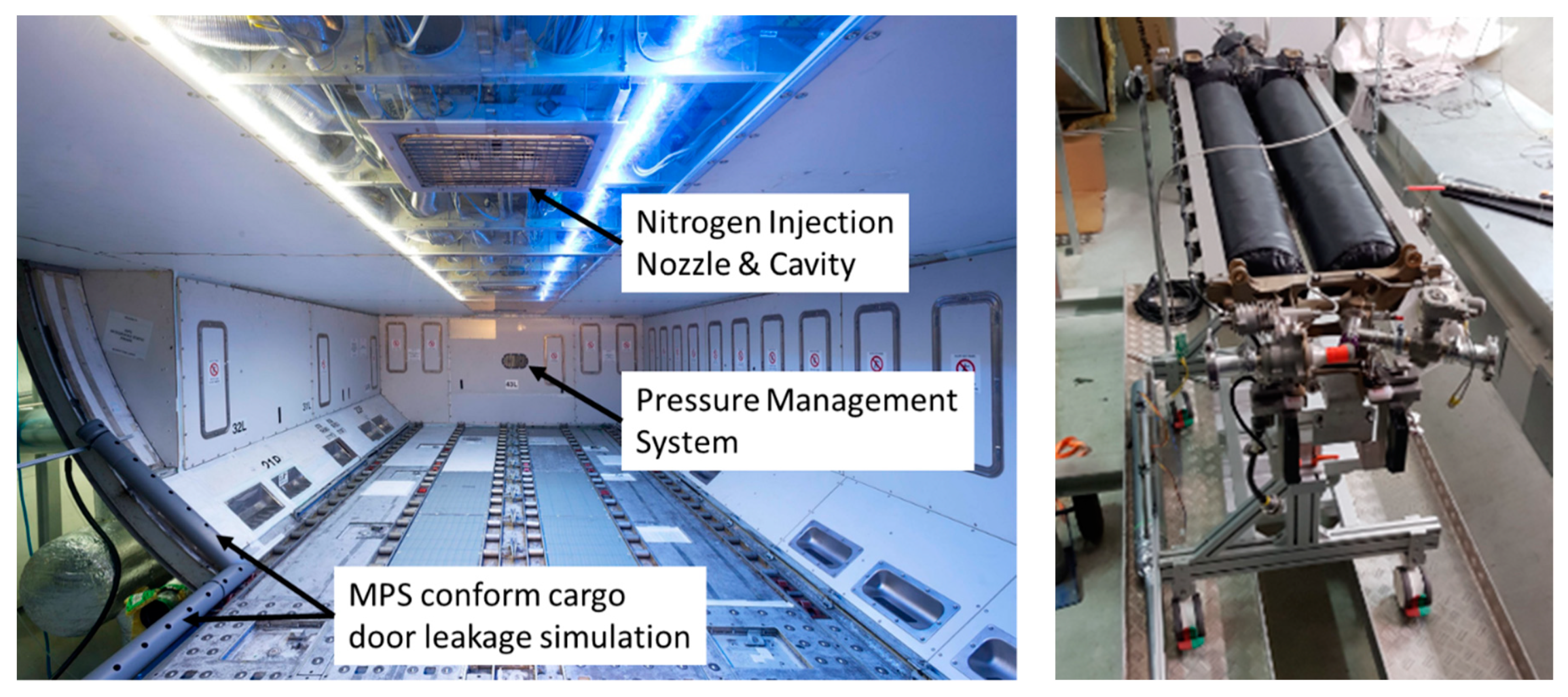
2.2.1. Cargo Bay Refurbishment
For the environmentally friendly fire protection system tests, the cargo bay was refurbished (
Figure 6, left). The main items of the refurbishment are as follows:
Original lining and ceiling panels from spare parts and A350 production series (except the center line, where Plexiglas was used to keep the agent distribution line visible).
Original panel sealing to meet airtightness requirements.
Integration of high pressure piping and three injection nozzles with a protective cavity in the ceiling.
Integration of the pressure management system (PMS) allowing the equalization of pressure between the cargo bay and adjacent bays.
Cargo door leakage simulation according to the MPS standard [
1] to generate the in-flight leakage across the door seal. In the test setup, this leakage was replicated by a piccolo tube distributed along the door seal. This tube is connected to a flow-controlled extraction fan.
Oxygen concentration sensors are distributed in the cargo hold to assess the local oxygen and nitrogen concentrations.
The nitrogen needed to perform the inertion task was taken from industrial bottles placed outside the low pressure vessel. The bottles were on a scale to measure the consumed amount of nitrogen. Furthermore, an On-Board Inert Gas Generating System (OBIGGS,
Figure 6, right) demonstrator, derived from the fuel tank inertion technology, has been integrated in the flight test facility. The OBIGGS consists of selective air separation membranes that separate hot pressurized air into a nitrogen rich fraction used for cargo bay inertion and an oxygen rich fraction dumped overboard.
2.2.2. Typical Test
At the beginning of the test, heat dummies in the cabin and the cabin ventilation system are turned on. Then, the pressure in the low pressure vessel is reduced from ambient pressure to 750 hPa (8000 ft.). The leakage flow simulation through the cargo door is activated. Due to this suction, air from the underfloor area enters the cargo bay through the PMS. When the pressure, airflow rates, and temperatures are stabilized, the test begins.
A sufficiently large amount of nitrogen is supplied within 3 min to bring down the oxygen concentration in the cargo hold below the flammability point. Dinesh et al. [
11] suggest that the remaining oxygen level should be 13% or lower. The exact amount of nitrogen depends on the cargo hold size and the target concentration.
A metered flow of pure bottled nitrogen or nitrogen enriched air (NEA) provided by the OBIGGS is supplied. The required flow rate depends on the air tightness of the door seal as this air is replaced by the ingress of new, fresh air through the PMS into the cargo hold.
The descent phase is critical in terms of oxygen concentration due to the repressurization from 750 hPa to ground pressure. This repressurization is performed by supplying ambient air through the PMS. Thus, a noticeable amount of fresh air enters the cargo hold and increases the oxygen concentration. There are two strategies to cope with this: either the holding system increases its flow accordingly or the oxygen concentration is kept sufficiently low prior to descent to meet the requirement at the end of the descent.
3. Test and Model Validation Results
In this section, the test and model validation results are presented. The presented test uses NEA from the OBIGGS during the holding phase and follows the strategy to provide a sufficiently low oxygen concentration in the cargo hold to meet the requirement of concentrations below 13% after descent.
Test Sequence and Result
For model validation, the test sequence set out in
Table 1 was performed. Times reflect the elapsed minutes. It simulates a flight where the fire suppression system is activated during cruising and operates until landing at the airport.
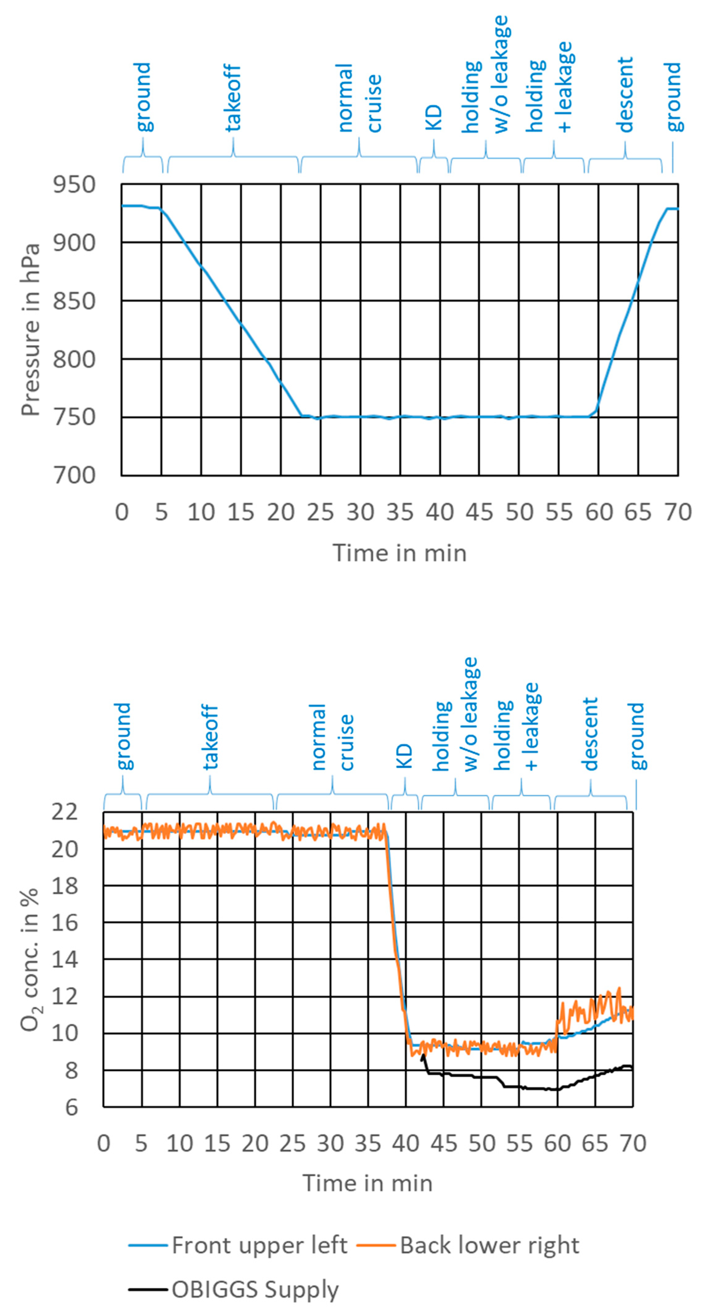
The pressure chart is shown in
Figure 7 (top). To increase the pressure in the cargo bay from 750 hPa to 940 hPa, an air amount of approx. 11.7 m³ is supplied during descent. Taking into account the time of 9 min to reach ground pressure, this corresponds to an average air ingress rate of 21.6 L/s, thus noticeably higher than the leakage rate though the door seal.
Figure 7, bottom shows the oxygen concentration in the front upper left and back lower right position. It is obvious that the knock-down leads to an instantaneous drop in the oxygen concentration in the cargo hold. During the holding phase, NEA is supplied with a residual oxygen concentration of 7–8%. The measurement indicates that the oxygen concentration is uniform in the cargo bay and no relevant gradient builds up with or without the activated door leakage system. The reason for this is that leakage and the holding supply rate are both balanced at 9 L/s, thus no major ingress of fresh air occurs during this phase. While the door leakage is not activated, the supply of NEA leads to an outflow of air through the PMS. This outflow is redirected to the door leakage when the system is started.
The re-pressurization leads to a higher gradient of oxygen concentration throughout the cargo hold. The pressure management system and thus the ingress of fresh air is located at the rear wall. Therefore, the local concentration becomes higher in this region during descent. Nevertheless, the requirement to remain below 13% is still met at this “weakest” point.
The experiment shows that the OBIGGS stably delivers NEA with 7–8% residual oxygen concentration throughout the mission profile.
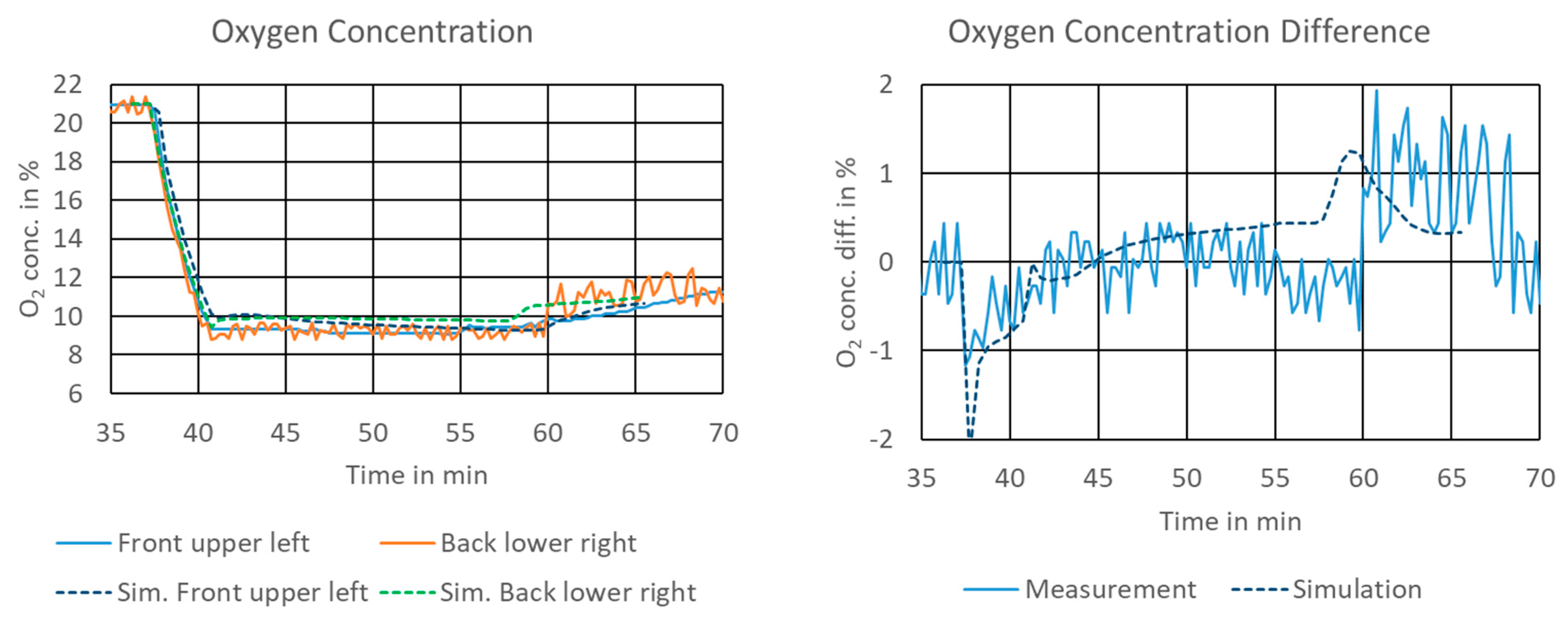
The same mission profile, starting with knockdown and ending with landing, was applied to the simulation model. The zonal modelling approach accurately predicts the magnitude of the oxygen concentration (
Figure 8, left). The deviation between simulated and measured oxygen concentrations remains below 1%.
The measured and simulated gradients of the oxygen concentration are shown (
Figure 8, right). For this, both sensor readings were subtracted from the concentrations in the zones representative of the sensors. The concentration difference was accurately predicted with a maximum deviation of the simulated and measured difference of less than 1%. The dynamic response of the simulation model was faster than the actual test data. One reason could be the time delay in the sensors to react to such changes or the integration scheme used by the Modelica/Dymola solver.
An exemplary plot of the oxygen distribution during descent, together with the location of the evaluated zones in the cargo hold is shown in
Figure 9.
4. Conclusions
This paper presents a model validation case for the agent distribution of environmentally friendly fire protection systems. The validated model can now serve to predict critical load cases for the cargo hold, the effect of geometry change, e.g., when considering a different aircraft size, and is extendable for other agents. Through this approach, a transient design tool for the cargo fire protection mission has been developed.
From the model validation it is deduced that the IESS is capable of predicting the oxygen concentration in the cargo hold for a transient mission profile within 1% accuracy. For a model-based nitrogen fire suppression system design, this maximal detected deviation suggests aiming for a design setpoint of 12% oxygen concentration in order to reliably meet the requirement of a residual oxygen concentration of 13%.
The presented example considers an empty cargo hold. Future research will consider the effect of containers placed in the cargo hold leading to the obstruction of the airflow paths.
Author Contributions
Conceptualization, V.N. and A.P.; methodology, A.P.; software, A.P.; validation, A.P.; formal analysis, M.P.; investigation, M.P.; resources, V.N.; data curation, M.P.; writing—original draft preparation, V.N.; writing—review and editing, A.P.; visualization, V.N.; supervision, A.P.; project administration, V.N.; funding acquisition, V.N. All authors have read and agreed to the published version of the manuscript.
Funding
The work was conducted with financial support from the Clean Sky 2 program under Grant Agreement number: LPA-IADP CS2-LPA-GAM-2018-2019-01. The authors are responsible for the content of this publication.
Data Availability Statement
A file with data used for the plots in this paper is uploaded together with the paper.
Conflicts of Interest
The authors declare no conflict of interest.
Table of Acronyms
| Acronym | Explanation |
| CAD | Computer-Aided Design |
| CFD | Computational Fluid Dynamics |
| ECS | Environmental Control System |
| EFFP | Environmentally Friendly Fire Protection |
| FTF | Flight Test Facility |
| IESS | Indoor Environment Simulation Suite |
| KD | Knockdown |
| MPS | Minimum Performance Standard [1] |
| NEA | Nitrogen-Enriched Air |
| OBIGGS | On-Board Inert Gas Generation System |
| ODP | Ozone Depletion Potential |
| PMS | Pressure Management System |
References
- Reinhardt, J.W. Minimum Performance Standard for Aircraft Cargo Compartment Halon Replacement Fire Suppression Systems; 2nd Update; US Department of Transportation Federal Aviation Administration: Springfield, VA, USA, 2005.
- Hetrick, T.; Todd, M. Investigation of Hold Time Calculation Methodologies for Total Flooding Clean Extinguishing Agents. In Proceedings of the SUPDET Conference, Orlando, FL, USA, 5–8 March 2007. [Google Scholar]
- Li, Y.F.; Chow, W. A Zone Model in Simulating Water Mist Suppression on Obstructed Fire. Heat Transf. Eng. 2006, 27, 99–115. [Google Scholar] [CrossRef]
- Vaari, J. A transient one-zone computer model for total flooding water mist fire suppression in ventilated enclosures. Fire Saf. J. 2002, 37, 229–257. [Google Scholar] [CrossRef]
- Yoon, S.S.; Kim, H.Y.; Hewson, J.C.; Suo-Anttila, J.M.; Glaze, D.J.; Desjardin, P.E. A Modeling Investigation of Suppressant Distribution from a Prototype Solid-Propellant Gas-Generator Suppression System into a Simulated Aircraft Cargo Bay. Dry. Technol. 2007, 25, 1011–1023. [Google Scholar] [CrossRef]
- Pathak, A.; Norrefeldt, V.; Lemouedda, A.; Grün, G. The Modelica Thermal Model Generation Tool for Automated Creation of a Coupled Airflow, Radiation Model and Wall Model in Modelica. In Proceedings of the 10th International Modelica Conference, Lund, Sweden, 10–12 March 2014; Linköping University Electronic Press: Linköping, Sweden, 2014; pp. 115–124. [Google Scholar]
- Norrefeldt, V.; Grün, G. VEPZO—Velocity Propagating Zonal Model for the prediction of airflow pattern and temperature distribution in enclosed spaces. In Proceedings of the 9th International Modelica Conference, Munich, Germany, 3–5 September 2012. [Google Scholar]
- Pathak, A.; Norrefeldt, V.; Grün, G. Modelling of radiative heat transfer in Modelica with a mobile solar radiation model and a view factor model. In Proceedings of the 9th International Modelica Conference, Munich, Germany, 3–5 September 2012. [Google Scholar]
- Norrefeldt, V.; Pathak, P.; Siede, M.; Lemouedda, A. Thermal Model and Thermal Model Generation Tool for Business Jet Applications. In Proceedings of the Greener Aviation Conference, Brussels, Belgium, 12–14 March 2014. [Google Scholar]
- Pathak, A.; Norrefeldt, V.; Grün, G. Simulation tool for environment friendly aircraft cargo fire protection system evaluation. In Proceedings of the Aerospace Europe Conference, Bordeaux, France, 25–28 February 2020. [Google Scholar]
- Dinesh, A.; Benson, C.M.; Holburn, P.; Sampath, S.; Xiong, Y. Performance evaluation of nitrogen for fire safety application in aircraft. Reliab. Eng. Syst. Saf. 2020, 202, 107044. [Google Scholar] [CrossRef]
| Publisher’s Note: MDPI stays neutral with regard to jurisdictional claims in published maps and institutional affiliations. |
© 2021 by the authors. Licensee MDPI, Basel, Switzerland. This article is an open access article distributed under the terms and conditions of the Creative Commons Attribution (CC BY) license (http://creativecommons.org/licenses/by/4.0/).


