Abstract
In view of the uncertainty of model parameters, the influence of external disturbances and sensor noise on the flight of coaxial rotor aircraft during autonomous flight, a robust backstepping sliding mode control algorithm for the position and attitude feedback control system is studied to solve the trajectory tracking problem of an aircraft in the case of unknown external interference. In this study, a non-linear dynamic model based on a disturbed coaxial rotor aircraft was established for an unknown flight. Then, a non-linear robust backstepping sliding mode controller was designed, which was divided into two sub-controllers: the attitude controller and the position controller of the coaxial rotor aircraft. In the controller, virtual control was introduced to construct the Lyapunov function to ensure the stability of each subsystem. The effectiveness of the proposed controller was verified through numerical simulation. Finally, the effectiveness of the backstepping sliding mode control algorithm was verified by flight experiments.
1. Introduction
In recent years, with the development of embedded electronic technology and sensor technology, the research and development of unmanned aerial vehicles (UAVs) has become a hot topic. In the next few years, low-cost autonomous navigation UAV systems will become a new tool for civil and military applications. Rotor UAVs have many advantages, such as compact structure, small size, and hovering ability, and are widely used. They are especially suitable for reconnaissance and attacks in sensitive and uncertain environments. In medical rescues and natural disasters, it is sufficient to encounter difficult or dangerous areas to use these in order to avoid casualties and property losses [1,2].
Compared with fixed-wing UAVs, rotor drones have the advantage of hovering at low speeds when performing fixed-point, accurate, and detailed missions, and do not require the establishment of dedicated runways or ejection frames, which are more convenient than fixed-wing UAVs. However, compared with fixed-wing UAVs, the longer flight time of the rotor UAVs is a disadvantage and cannot be observed remotely. During the flight, the concealment is not good, and the target is easily exposed. After analyzing various types of existing rotor unmanned aerial vehicle, it is proposed that the rotor unmanned aerial vehicle is placed as projectile and quickly reaches the specified area through the energy provided by the launch device. It is then transformed into a coaxial rotor aircraft for reconnaissance, surveillance, interference, lighting, and attacks [3,4,5]. A flowchart of this process is shown in Figure 1. Through the launcher, the projectile is carried to the designated area, the parachute is used to decelerate, and the task is carried out in the designated area.
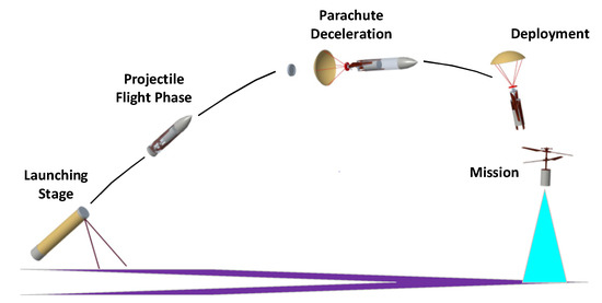
Figure 1.
Flowchart of gun launch coaxial rotor aircraft.
In an uncertain environment, the stable flight of a coaxial dual-rotor aircraft is an indispensable part of various missions. Therefore, the control problem of rotorcraft has aroused the interest of many researchers. Many control methods have been used in the design of various aircraft control systems, including linear and non-linear control methods. In the linear system theory, the control method is the single input single output (SISO) feedback control method based on the linear approximation of the aircraft model. The main control algorithms are cascade proportion integral differential (PID)control, quadratic linear control (LQ), linear quadratic Gaussian (LQG) control, and H ∞ control. PID control enables the stable controlled flight of different forms of UAVs, usually using a string-level PID control approach, and has been successfully tested on several rotorcraft UAV platforms. References [6,7] compared different control methods for helicopter autopilot design, modelled the effective thrust moment for hovering and low-speed flight based on non-linear dynamic equations, and verified the performance of the controller. Reference [8] proposed a quaternion-based feedback control scheme for the exponential attitude stabilization of a quadrotor vertical take-off and landing aerial robot known as a quadrotor. Reference [9] proposed a control scheme based on PID control with the aim of obtaining a stable attitude of a quadrotor aircraft. LQ is an optimal control method. To obtain the desired stable flight state, a better robustness can be obtained by designing the weighting matrix of the controller. However, this stability can only be guaranteed under the assumption that the model is completely known and requires the signal to be free of noise. This approach has been successfully implemented on several experimental platforms. In reference [10] the tracking control for a small-scale helicopter was designed, the weighting between the state tracking performance and control power expenditure was analyzed, and the overall performance of the control design was evaluated based on the trajectory and control inputs. [11] evaluated the linear quadratic regulator (LQR) and classical controller synthesis techniques. The LQR provided a superior design for coupled dynamics attitude controllers, and preliminary flight test data confirmed the effectiveness of the control system design. A comparison between the PID method and the LQ method for quadrotor control is described in [12]. The LQG control method can accurately track control commands with good robustness for the influence of external disturbances and sensor measurement noise during UAV flight. In [13,14] describes the design procedure and experimental results of LQG control were applied to helicopters and quadrotors. In autonomous control, H ∞ control is the most commonly applied control structure. H ∞ considers the uncertainty of the model in the design process and uses an analytical approach to design the controller, where the model can meet the desired performance requirements under all conditions of uncertainty. This approach has been successfully tested on a large number of aircraft platforms [15,16]. A comparison of the LQG method and H ∞ method for helicopters is described in [17].
In autopilot design, although the above linear controller has robustness and closed-loop stability, it is suitable for working under pre-selected equilibrium conditions. When the aircraft deviates from the design operating conditions, the nonlinear coupling term degrades the performance of the aircraft. When an aircraft is subjected to unknown gusts, linearization becomes difficult to achieve. To overcome some limitations and shortcomings of the linear method, a non-linear flight control algorithm was developed and applied to an aircraft platform.
Many non-linear control algorithms have been applied in various aircraft in the autonomous control design of aircrafts. These include feedback linearization, dynamic inversion, singular disturbance, sliding mode control, backstepping, and other related adaptive nonlinear control algorithms. Feedback linearization is a conventional method that converts a nonlinear system into a linear system. However, the effectiveness of feedback linearization is highly dependent on the accuracy of the nonlinear model. In [18] the method was applied to an unmanned aircraft system. Dynamic inversion requires the selection of output control variables to stabilize internal dynamics. The internal dynamics were stabilized using a robust control term [19,20]. In [21], the design and stability analysis of a hierarchical controller for UAVs using singular perturbation theory. It is well known that the backstepping design method is widely used to control non-linear systems [22,23,24,25]. However, when the model has uncertainties and external disturbances, the algorithm cannot guarantee the stability of the closed-loop system. By adding the sliding mode, the disturbance can be overcome, and the robustness of the controller can be guaranteed [26,27,28].
In this study, a simplified six degrees of freedom (6–DOF) dynamic model of an aircraft based on the Newton–Euler formula was established for the influence of external disturbance and sensor noise on the aircraft during the autonomous flight of a coaxial rotor aircraft. A robust backstepping sliding mode control algorithm was designed for the position and attitude feedback control systems. In the control algorithm, the complex system is decomposed into a series of cascade subsystems, and the virtual control variables are added to construct some Lyapunov functions to ensure the stability of each subsystem. In the last subsystem, a sliding mode term composed of error is added to make a robust correction, and the actual control quantity is obtained. Finally, through the flight experiment of a coaxial rotor aircraft, the effectiveness of the backstepping sliding mode control algorithm was verified for the traditional algorithm.
The remainder of this paper is organized as follows. The kinematic model of the aircraft is described in Section 2. In Section 3, a backstepping sliding mode control algorithm for attitude control and position control of a coaxial rotor aircraft is described. In Section 4, the feasibility of the developed solution for a coaxial rotor aircraft is demonstrated by a numerical simulation of the backstepping sliding mode control algorithm. In Section 5, the effectiveness of the backstepping sliding mode control algorithm is verified by flight experiments and compared with the traditional PID control algorithm. The conclusions and future work are discussed in Section 6.
2. Kinetic Model
To derive the mechanical model of the system, the Newton–Euler motion equation is used to establish the coaxial rotor aircraft model with two reference systems: the body coordinate system and the navigation coordinate system [29]. The body coordinate system is represented by {}. The directions of the three axes point to the front and right ground, and the coordinate origin coincides with the centroid of the aircraft. The navigation coordinate system {} is used to describe the position and attitude information of the aircraft. and are the position and speed in the navigation coordinates, respectively. is the Euler angle of the roll, pitch, and yaw. is the angular velocity of the relevant angle. The rotation matrix is the rotation matrix between the navigation coordinate system and the body coordinate system. The expression is defined by Equation (1). The coordinate system and model block diagram are shown in Figure 2.
where c(*) = cos(*) and s(*) = sin(*). is an orthogonal matrix, and is invertible.
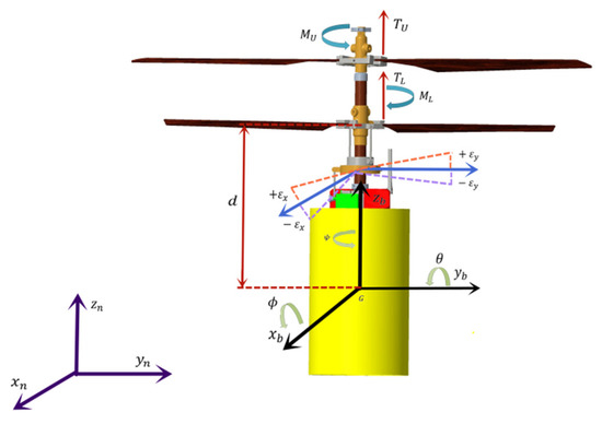
Figure 2.
Coordinate system and model block diagram.
According to the kinematics equation of position translation, the velocity of a rigid body corresponds to the time derivative of the center of gravity in the navigation coordinate system. The expression is defined by Equation (2).
Matrix is the relation between the Euler angle and angular velocity as defined in Equation (3).
The rotational kinematics equation relates the time derivative of the roll angle , the pitch angle and the yaw angle to the instantaneous angular velocity . The denominator of some elements in matrix is . In this case, will lead to singularity problems, which should be avoided. The expression is defined by Equation (4).
In Equations (5) and (6), the coaxial rotor aircraft platform is regarded as a rigid body, and the 6DoF dynamics are described by the following Newton–Euler equation:
where , are the projections of on the axes of the body coordinate system, , are the projections of on the axes of the body coordinate system. is the total mass of the coaxial rotor, is the rotational inertia of the coaxial rotor aircraft in Equation (7).
The coaxial rotor aircraft is designed to be symmetrical in both the longitudinal and transverse directions, so are very small and can be assumed to be zero and the force of the coaxial rotor aircraft mainly affects the gravity in the navigation coordinate system, the lift generated by the rotor blade, the waving force generated by the rotor control mechanism and the air resistance generated by the fuselage. The gravity acting on the z-axis of the navigation coordinate system is in Equation (8).
where is the acceleration of gravity. The lift generated by the rotor is:
The lift coefficient of upper and lower rotor, angular velocity of upper and lower rotor, and lift generated by upper blades.
where , are the flapping angles of the swashplate of the lower rotor, the transformation matrix from the body to the swashplate of the lower rotor, and the lift and flapping force produced by the lower rotor are in Equation (12).
Total lift is defined as Equation (13).
When the coaxial rotor aircraft is flying in the air, owing to air resistance, its fuselage will withstand resistance . This resistance is related to the velocity and surface area of the coaxial rotor aircraft. The fuselage is defined by Equation (14).
where are the resistance areas along the body coordinate system, and the lower rotor produces the air-induced velocity. The total force of the coaxial rotor aircraft is:
The torque of the action of the coaxial rotor aircraft is composed of the resistance torque produced by the upper and lower rotors and the flapping torque produced by the lower rotor swashplate mechanism.
The distance from the centroid G to the lower rotor is d, and the total torque is:
where air resistance moment coefficient.
Considering the structural characteristics and actual working conditions of the coaxial rotor aircraft, the following reasonable model simplification can be carried out: (1) When the coaxial rotor aircraft is flying at low speed, the pitch angle and roll angle maintain a small angle change, that is, the pitch angle and roll angle change in the range of [−20°, 20°]. It can be considered that the Euler angle velocity is equal to the angular velocity in the body coordinate system. (2) The air friction and friction torque, gyroscopic effect, angular velocity coupling, and external environment disturbance are considered as the total uncertainties of the system. Therefore, the model can be simplified as Equations (17)–(20).
and represent the total uncertainty of the system force and torque, including the unmodeled dynamics and total external disturbance, which satisfies the boundedness, namely , .
The coaxial rotor aircraft is described as a nonlinear system, controlled by four control inputs and , upper and lower rotor speeds, , along the rolling axis and pitching axis of the swashplate mechanism flapping angle control. The control input model can be simplified as Equations (21)–(24).
3. Design of Robust Backstepping Sliding Mode Control Algorithm
In this section, a robust backstepping sliding mode controller is designed for the position and attitude feedback control system to solve the trajectory-tracking problem of an aircraft under unknown external disturbances. The design process of the robust backstepping sliding mode control algorithm involves decomposing a complex system into a series of cascade subsystems. In each subsystem, virtual control is added to construct a partial Lyapunov function to ensure the stability of each subsystem. In the last subsystem, the sliding term composed of the error is added to the robust correction to obtain the actual control. Therefore, starting from the lowest-order subsystem, the virtual control variables that meet the requirements are gradually designed to obtain the final real control law, which greatly simplifies the design of the control algorithm. A control block diagram is shown in Figure 3.
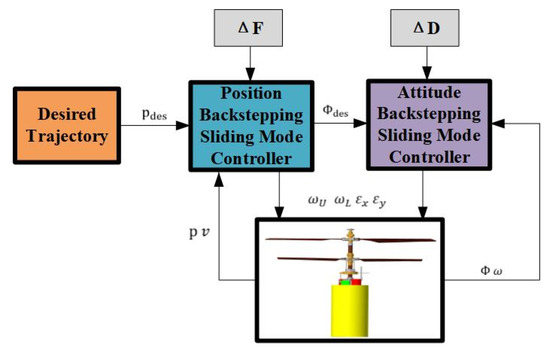
Figure 3.
Control block diagram.
3.1. Attitude Control Method
The first goal is to design a robust backstepping sliding mode control algorithm for attitude control. The attitude angle and angular velocity of the control algorithm track the desired attitude angle ) and the desired angular velocity under the action of external disturbance . The attitude angle tracking error is
Then, the attitude angle tracking error derivative
Define the Lyapunov function [30]:
Define , where is a normal number and is a virtual control
Then , and
Define switching functions:
Since , it is obvious that if , then and . Therefore, the following design is required to define the Lyapunov function:
Then
The design controller is:
where, and are positive constant.
Substituting the design controller into the expression of , we can obtain:
Taking
due to
where . If is guaranteed to be a positive definite matrix, there is:
due to:
By taking the values of , and , we can make to ensure that is a positive definite matrix, so that .According to the principle of Lasalle invariance, when is taken, then , , thus, , then .
3.2. Position Control Method
Similarly, a robust backstepping sliding mode control algorithm for position control is designed. In this control algorithm, position p and velocity v track the expected position and the expected velocity under the action of external disturbance . Position control tracking error is as follows:
then the attitude angle tracking error derivative
Define the Lyapunov function:
Define , where is a positive constant and is a virtual control,
then and
Define switching functions:
where , since , then
Because , it is obvious that if , then , and . Therefore, the next design is required.
Then
the design controller is:
where, and are positive constant.
Substituting the design controller into the expression of , we can obtain:
Taking
due to
where . If is guaranteed to be a positive definite matrix, there is
due to
By taking the values of , and , we can make to ensure that is a positive definite matrix, so that . According to the principle of Lasalle invariance, when is taken, then , , , thus, , , then .
4. Simulation Analysis
In this study, the performance of the proposed control algorithm is illustrated through a numerical simulation. Considering the mathematical model given in (17)–(20), the basic parameters of a coaxial rotor aircraft are listed in Table 1, and the initial conditions of all states are zero, . The attitude robust backstepping sliding mode controller defined by (33) and the position robust backstepping sliding mode controller defined by Equation (48) was used. Taking,, the control parameters are presented in Table 2. The desired trajectory was selected as follows:

Table 1.
Model parameters of coaxial rotor aircraft.

Table 2.
Control parameters.
Aerodynamic force and moment , are selected as:
The desired attitude angle and desired position were set to zero. To explore the effectiveness of the proposed control algorithm, the following two cases were considered, and each simulation lasted for 30 s.
4.1. Numerical Simulation under Aerodynamic Interference
In the case of external aerodynamic interference, the position and attitude-tracking control of a coaxial rotor aircraft are numerically simulated. Figure 4a shows the three-dimensional trajectory tracking of a coaxial rotor aircraft. In position control, backstepping sliding mode control uses a symbolic function to handle the uncertainty problem and shows good robustness, exhibiting good tracking performance with little uncertainty and almost no chattering. Figure 4b shows the tracking of the desired position and the actual position of the coaxial rotor aircraft. Figure 4c shows the tracking of the desired attitude angle and the actual attitude angle of the coaxial rotor aircraft. In attitude control, the backstepping sliding mode exhibits a stable response that perfectly tracks the control command as the vehicle attitude is adjusted in the initial phase to produce a sharp change, and it shows a good effect under a sharp change in the control command. Figure 4d shows the output control of the coaxial rotor aircraft, and its control is continuous, which is suitable for application to an actual model. As shown in the figure, when the external aerodynamic disturbance is added, the proposed control algorithm can track the target trajectory well, indicating that the robustness and stability of the proposed control method are guaranteed.
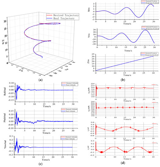
Figure 4.
Numerical simulation under aerodynamic interference. (a) Three-dimensional trajectory tracking; (b) expected and actual position responses; (c) expected and actual attitude response diagrams; (d) the virtual control input.
4.2. Numerical Simulation under Sensor Interference
In this case, the disturbance of uncertain trajectory tracking is mainly derived from the feedback signal of the sensor noise communication channel of the coaxial rotor aircraft. The white Gaussian noise signal of the position sensor with a variance of 0.01 and the white Gaussian noise signal of the attitude sensor with a variance of 0.0001 were added to simulate the disturbance of the system. When the parameter design of the system satisfies the stability conditions given in (33) and (48), although there is sensing noise, the proposed control algorithm can successfully track the desired position and attitude, and the scheme is robust. Figure 5a shows the three-dimensional trajectory tracking of a coaxial rotor aircraft. Figure 5b shows the tracking of the desired position and the actual position of the coaxial rotor aircraft. Figure 5c shows that the real attitude can be tracked, although the attitude fluctuates under the Gaussian white noise signal. Although there is chattering in position control and attitude control, backstepping sliding mode control can successfully track control commands with external perturbations, proving a strong tracking capability. Figure 5d shows that the instability of the control signal affects the flight state.
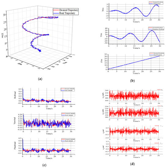
Figure 5.
Analysis chart with disturbance. (a) Three-dimensional trajectory tracking; (b) expected and actual position responses; (c) expected and actual attitude response diagrams; (d) virtual control input.
5. Experimental Tests
To verify the feasibility and practicability of the robust backstepping sliding mode control algorithm proposed in this study, it is necessary to apply this algorithm to a prototype machine for experimental testing. The traditional flight control algorithm used in this study is cascade PID, which is divided into inner loop and outer loop PID for feedback control of position, speed and attitude. The adjusted main control gains are P in the outer loop and P, I and D in the inner loop. The PID parameters are obtained through bench and flight tests. Figure 6 shows the principle prototype of a coaxial rotor aircraft. The attitude of the aircraft is very stable during flight according to the flight test data compared with the cascade PID control of the traditional flight control algorithm.
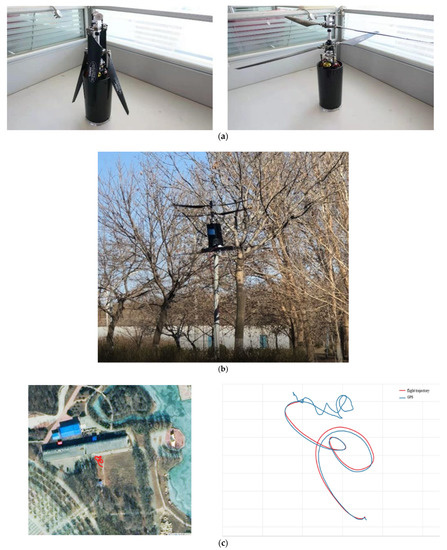
Figure 6.
Principal prototype and flight test. (a) Principal prototype; (b) flight experiment; (c) flight trajectory.
Figure 7 shows the position change of the coaxial twin-rotor aircraft during the flight experiment. The aircraft position curve obtained by the robust backstepping sliding mode control algorithm is significantly better than that obtained using the traditional control algorithm. Under the robust backstepping sliding mode control, the position fluctuation of X, Y, Z, and aircraft in all directions is less than ±0.8 m. In this process, the flight accuracy of the aircraft is high, and fixed-point hovering can be realized. In the experimental test, the vibration of the coaxial rotor aircraft body is inevitable, mainly owing to the vibration of the aircraft motor, blade flapping, and gear transmission. It is acceptable to control the vibration of the body within a certain range.
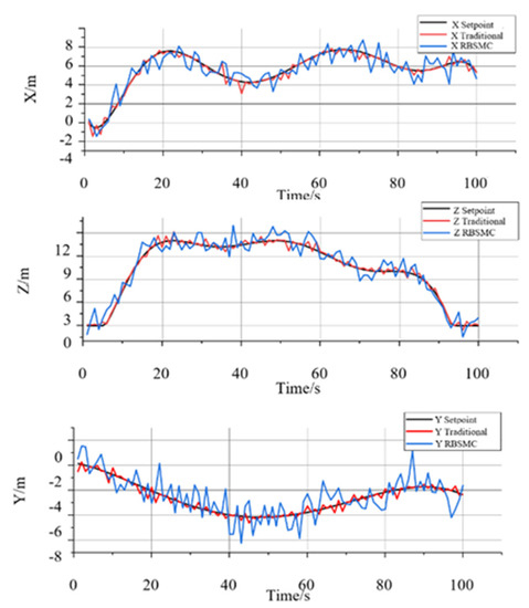
Figure 7.
Traditional versus RBSMC positions.
The change in the attitude angle of the traditional control algorithm and the robust backstepping sliding mode control algorithm are shown in Figure 8. Under robust backstepping sliding mode control, the roll angle and pitch angle of the aircraft were controlled within ±3°. Under the traditional control algorithm, the roll angle and pitch angle fluctuate significantly. The fluctuation frequency and amplitude of the roll angle and pitch angle under the robust backstepping sliding mode control algorithm are significantly smoother than those under the traditional control algorithm. Under the traditional control algorithm, the yaw angle changes significantly and frequently. Under the robust backstepping sliding mode control algorithm, the variation process of the yaw angle is continuous and stable.
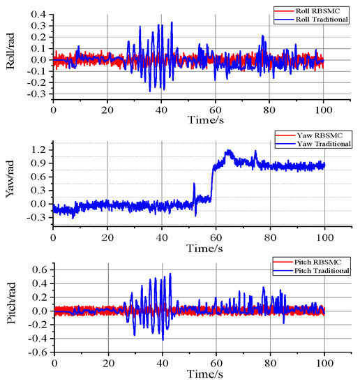
Figure 8.
Traditional versus RBSMC attitude.
6. Conclusions
In this paper, a robust non-linear control strategy for a coaxial rotor aircraft with uncertainty is proposed. The control algorithm combines the robust backstepping sliding mode control algorithm in the feedback control structure to effectively guarantee the trajectory tracking ability of the desired position and attitude. Through Lyapunov stability analysis, the stability and performance of the control system of a coaxial twin-rotor aircraft were studied. Aiming at the influence of parameter uncertainty, external disturbance and sensor noise on the flight of a coaxial rotor UAV model, a simplified 6-DOF dynamic model of an aircraft based on the Newton–Euler formula is established. A position and attitude feedback control system based on a robust backstepping sliding mode control algorithm was designed. The stability and performance of the control system of a coaxial rotor aircraft were studied using a Lyapunov stability analysis. According to the numerical simulation results under aerodynamic interference and sensor interference, the robust backstepping sliding mode control algorithm can effectively control the coaxial dual-rotor aircraft, even under severe uncertainty conditions. Finally, the feasibility and effectiveness of the backstepping sliding mode control algorithm for a coaxial rotor aircraft are verified by comparing the flight test data with the traditional cascade PID flight control algorithm.
The aim of future research is to improve the stability of the flight systems. The coaxial rotor aircraft in this study was independently developed by the team, and the mechanical system vibration was uncertain due to motor vibration, transmission vibration, and aircraft blade flapping. At the same time, the BSMC method has the characteristic of discontinuous switching, which causes chattering in the system. Therefore, smooth filtering of the control signal can be considered, and the disturbance observer can be used to estimate and compensate for the external uncertainty.
Author Contributions
Conceptualization, J.X. and Y.H.; methodology, J.X.; software, J.W.; validation, J.X., Y.H. and L.L.; formal analysis, J.X.; investigation, J.X.; resources, J.X.; data curation, J.W.; writing-original draft preparation, J.X.; writing-review and editing, Y.H.; visualization, J.W.; supervision, Y.H.; project administration, J.X.; funding acquisition, L.L. All authors have read and agreed to the published version of the manuscript.
Funding
This research received no external funding.
Conflicts of Interest
The authors declare no conflict of interest.
References
- Martorana, R. WASP A High-g Survivable UAV. In Proceedings of the AIAA’s 1st Technical Conference and Workshop on Unmanned Aerospace Vehicles, Portsmouth, VA, USA, 20–23 May 2002. [Google Scholar]
- Smith, T.; McCoy, E.; Krasinski, M. Ballute and parachute decelerators for FASM/QuickLook UAV. AIAA Paper 2003–2142. In Proceedings of the 17th AIAA Aerodynamic Decelerator Systems Technology Conference and Seminar, Monterey, CA, USA, 19–22 May 2003. [Google Scholar]
- Roussel, E.; Gnemmi, P.; Changey, S. Gun-Launched Micro Air Vehicle: Concept, challenges and results. In Proceedings of the Unmanned Aircraft Systems (ICUAS), 2013 International Conference on IEEE, Atlanta, GA, USA, 28–31 May 2013. [Google Scholar]
- Gnemmi, P.; Haertig, J. Gun Launched Micro Air Vehicle: A New Concept for MAV’s. In Proceedings of the European Micro Air Vehicle Conference and Flight Competition (EMAV 2008), Braunschweig, Germany, 8–10 July 2008. [Google Scholar]
- Gnemmi, P. Conception and Manufacturing of a Projectile-Drone Hybrid System (GLMAV). IEEE/ASME Trans. Mechatron. 2017, 22, 940–951. [Google Scholar] [CrossRef]
- Shim, H.; Koo, T.; Hoffmann, F.; Sastry, S. A comprehensive study of control design for an autonomous helicopter. In Proceedings of the 37th IEEE Conference on Decision and Control, Las Vegas, NV, USA, 10–13 December 2002; Volume 4, pp. 3653–3658. [Google Scholar] [CrossRef]
- Kim, H.J.; Shim, D.H. A flight control system for aerial robots: Algorithms and experiments. Control. Eng. Pract. 2003, 12, 389–1400. [Google Scholar] [CrossRef]
- Tayebi, A.; Mcgilvray, S. Attitude stabilization of a four-rotor aerial robot. Decision and Control. In Proceedings of the 2004, CDC, 43rd IEEE Conference on IEEE, Seville, Spain, 12–15 December 2005. [Google Scholar]
- Li, J.; Li, Y. Dynamic analysis and PID control for a quadrotor. In Proceedings of the 2011 IEEE International Conference on Mechatronics and Automation IEEE, Beijing, China, 7–10 August 2011. [Google Scholar]
- Budiyono, A.; Wibowo, S.S. Optimal Tracking Controller Design for a Small Scale Helicopter. J. Bionic Eng. 2007, 4, 271–280. [Google Scholar] [CrossRef]
- White, J.E.; Phelan, J.R. Stability augmentation for a free flying ducted fan. Guidance. In Proceedings of the Navigation and Control Conference, Boston, MA, USA, 14–17 August 1986. [Google Scholar]
- Bouabdallah, S.; Noth, A.; Siegwart, R. PID vs. LQ control techniques applied to an indoor micro quadrotor. In Proceedings of the IEEE/RSJ International Conference on Intelligent Robots & Systems, Sendai, Japan, 28 September 2004. [Google Scholar]
- Cai, G.; Cai, A.K.; Chen, B.M.; Lee, T.H. Construction, Modeling and Control of a Mini Autonomous UAV Helicopter. In Proceedings of the IEEE International Conference on Automation and Logistics, Qingdao, China, 1–3 September 2008. [Google Scholar]
- Mokhtari, A.; Benallegue, A.; Belaidi, A. Polynomial Linear Quadratic Gaussian and Sliding Mode Observer for a Quadrotor Unmanned Aerial Vehicle. J. Robot. Mechatron. 2005, 17, 483–495. [Google Scholar] [CrossRef]
- Gadewadikar, J.; Lewis, F.; Subbarao, K.; Chen, B.M.; Peng, K. H-Infinity Static Output-Feedback Control for Rotorcraft. J. Intell. Robot. Syst. 2006, 54, 629–646. [Google Scholar] [CrossRef]
- Schafroth, D.; Bermes, C.; Bouabdallah, S.; Siegwart, R. Modeling, system identification and robust control of a coaxial micro helicopter. Control. Eng. Pract. 2010, 18, 700–711. [Google Scholar] [CrossRef]
- Bendotti, P.; Morris, J.C. Robust hover control for a model helicopter. In Proceedings of the 1995 American Control Conference-ACC’9, Seattle, WA, USA, 21–23 June 1995. [Google Scholar]
- Lee, D.; Kim, H.J.; Sastry, S. Feedback linearization vs. adaptive sliding mode control for a quadrotor helicopter. Int. J. Control Autom. Syst. 2009, 7, 419–428. [Google Scholar] [CrossRef]
- Mokhtari, A.; M’Sirdi, N.K.; Meghriche, K.; Belaidi, A. Feedback linearization and linear observer for a quadrotor unmanned aerial vehicle. Adv. Robot. 2006, 20, 71–91. [Google Scholar] [CrossRef][Green Version]
- Das, A.; Subbarao, K.; Lewis, F. Dynamic inversion with zero-dynamics stabilisation for quadrotor control. IET Control. Theory Appl. 2009, 3, 303–314. [Google Scholar] [CrossRef]
- Bertrand, S.; Guénard, N.; Hamel, T.; Piet-Lahanier, H.; Eck, L. A hierarchical controller for miniature VTOL UAVs: Design and stability analysis using singular perturbation theory. Control Eng. Pract. 2011, 19, 1099–1108. [Google Scholar] [CrossRef]
- Almakhles, D.J. Robust Backstepping Sliding Mode Control for a Quadrotor Trajectory Tracking Application. IEEE Access 2019, 8, 5515–5525. [Google Scholar] [CrossRef]
- Safeer, U. Robust Backstepping Sliding Mode Control Design for a Class of Underactuated Electro–Mechanical Nonlinear Systems. J. Electr. Eng. Technol. 2020, 15, 1821–1828. [Google Scholar]
- Chiang, H.K.; Fang, C.C.; Hsu, F.J. Robust variable air speed control of a nonlinear fan system based on backstepping sliding mode control techniques. Adv. Mech. Eng. 2016, 8, 1687814016651373. [Google Scholar] [CrossRef]
- Chen, F.; Jiang, R.; Zhang, K.; Jiang, B.; Tao, G. Robust backstepping sliding-mode control and observer-based fault estimation for a quadrotor UAV. IEEE Trans. Ind. Electron. 2016, 63, 5044–5056. [Google Scholar] [CrossRef]
- Napole, C.; Barambones, O.; Derbeli, M.; Calvo, I. Advanced Trajectory Control for Piezoelectric Actuators Based on Robust Control Combined with Artificial Neural Networks. Appl. Sci. 2021, 11, 7390. [Google Scholar] [CrossRef]
- Napole, C.; Derbeli, M.; Barambones, O. A global integral terminal sliding mode control based on a novel reaching law for a proton exchange membrane fuel cell system. Appl. Energy 2021, 301, 117473. [Google Scholar] [CrossRef]
- Derbeli, M.; Barambones, O.; Silaa, M.; Napole, C. Real-Time Implementation of a New MPPT Control Method for a DC-DC Boost Converter Used in a PEM Fuel Cell Power System. Actuators 2020, 9, 105. [Google Scholar] [CrossRef]
- Koehl, A.; Rafaralahy, H.; Boutayeb, M.; Martinez, B. Aerodynamic Modelling and Experimental Identification of a Coaxial-Rotor UAV. J. Intell. Robot. Syst. 2012, 68, 53–68. [Google Scholar] [CrossRef]
- Napole, C.; Barambones, O.; Derbeli, M.; Calvo, I.; Silaa, M.; Velasco, J. High-Performance Tracking for Piezoelectric Actuators Using Super-Twisting Algorithm Based on Artificial Neural Networks. Mathematics 2021, 9, 244. [Google Scholar] [CrossRef]
Publisher’s Note: MDPI stays neutral with regard to jurisdictional claims in published maps and institutional affiliations. |
© 2021 by the authors. Licensee MDPI, Basel, Switzerland. This article is an open access article distributed under the terms and conditions of the Creative Commons Attribution (CC BY) license (https://creativecommons.org/licenses/by/4.0/).