Abstract
To fulfill the objective of a predictive tool for rotorcraft, comprehensive analysis (CA) needs to be capable of providing both accurate and time-efficient predictions of rotor air loads and structural loads. The more recent methodology based on comprehensive analysis coupled with high-fidelity computational fluid dynamics (CFD) has shown improved predictions of air loads, but it has not the strength of computational efficiency and the versatility of stand-alone CA. The present article is concerned with modeling aerodynamics about helicopter rotors for CA. The aerodynamics about rotors are very complex, encompassing subsonic to transonic flow with unsteady, stalled behavior and 3D effects. CA treats aerodynamics as separated into local and global flows. Semi-empirical models of dynamic stall were created in the 1970s–1990s for modeling unsteady local aerodynamics, including stalled flow. Most of them fail to provide good predictions of experimental results and also suffer problems of numerical convergence. The main effort in this study is about modeling local aerodynamics based on the revised “ONERA–Hopf bifurcation model”. It is implemented in the comprehensive analysis code of ONERA according to a scheme that ensures numerical convergence. The experimental results obtained in the Wind Tunnel S1 of Modane (France) in 1991 on the Rotor 7A are considered for validation of the analysis under three flight test conditions: high-speed test, high-thrust tests with light stall and deep stall, respectively. There is a reasonable agreement between the predictions of CA with experimental results. The distinct features of the stall model are the modeling of the boundary-layer effects and the vortex-shedding phenomenon.
1. Introduction
To fulfill the objective of a predictive tool for rotorcraft, comprehensive analysis (CA) needs to be capable of providing both accurate and time-efficient predictions of rotor air loads. The more recent methodology based on comprehensive analysis coupled with high-fidelity computational fluid dynamics (CFD) has shown improved predictions of air loads [1], but it has not the strengths of computational efficiency and the versatility of stand-alone CA [2]. The present article is concerned with modeling aerodynamics about helicopter rotors for CA. Aerodynamics about the rotor result from the interaction of the incoming flow with the rotor and can be viewed as composed of a global flow that extends from far upstream of the rotor disc to far downstream and a local flow about the rotor blades [3]. The local aerodynamics about rotor blades are very complex, encompassing subsonic to transonic flow with unsteady, stalled regimes and 3D effects. Semi-empirical models of dynamic stall were created for modeling unsteady aerodynamics including stalled flow. Most of them were developed in the 1970s–1990s [4,5,6,7,8,9], but failed to provide good predictions of experimental results on the case of the UH-60A in the stalled regime [10]. Applied to another stalled test in a wind tunnel [11], most dynamic stall models also suffered problems of numerical convergence. Thus, there are two levels of difficulties for semi-empirical models: providing good physics description of aerodynamics and ensuring numerical convergence when implemented in comprehensive analysis codes.
The present article is concerned with the revision of the “ONERA–BH model” [9], to be named from now on as “ONERA–Hopf bifurcation model”. This model received initially a positive review [3], but was later severely criticized for its simulation of shedding-vortex phenomenon in the airfoil wake by a Van der Pol-type equation.
The experimental results obtained in the Wind Tunnel S1 of Modane (France) in 1991 on the Rotor 7A are considered for the illustration of the capabilities of the revised stall model. There are three flight conditions considered: the high-speed Test Point 312, the high-thrust Test Point 293 with light stall and the high-thrust Test Point 596 with deep stall. The computations are done mainly with the comprehensive analysis code ROTOR of ONERA [12] equipped with the revised dynamic stall model. Many studies have been made for the high-speed test point based on comprehensive analysis and then comprehensive analysis coupled with CFD techniques [13,14,15], but no correlation studies have been published for the second experimental test point, until recently, based on coupled analysis [16,17,18]. No study has been published for the third test point.
In the next section, the modeling of aerodynamics is detailed, first for the dynamic stall phenomenon. The aerodynamics about the rotor blades are inherently 3D; So, it is necessary to introduce various 3D effects, sweep effects, rotation effects and transonic tip relief effects. For the extreme aerodynamic condition of the high-speed test point, a correction of the induced velocity, affecting the global flow, is proposed. Corrections for the test environment involving the wind tunnel walls, the rotor stand and for the Reynolds number effects are also necessary. In the third section, the numerical implementation of the dynamic stall model in the comprehensive analysis code of ONERA is described. In the fourth section, the application of the comprehensive analysis code equipped with the dynamic stall model is made for three different test points of the Rotor 7A. Concluding remarks will be drawn in the last section.
2. Modeling Aerodynamics
The separation into local and global flows about the rotor blades is exploited in comprehensive analysis for solving the aerodynamics using different methods for the global flow field and the local flow field, respectively. Nevertheless, the interconnection between the two flow regions is taken into account; the inflow conditions on the rotor blades are determined by the global flow; and the aerodynamic forces acting on the blades influence the global flow. The global flow field is determined by momentum or wake methods. The aerodynamic forces on the blades are evaluated from tabulated tables of non-dimensional lift, drag and pitching moment coefficients with respect to aerodynamic incidence angles and Mach numbers. These tables, also called “polars”, are established by wind tunnel experiments on airfoils (generally completed by computation). A number of corrections are applied to the 2D values through models of dynamic stall. The most proclaimed objective of dynamic stall models is the modeling of dynamic stall aerodynamics. Actually, their objectives involve also modeling of unsteady aerodynamics prior to the occurrence of dynamic stall. There are various stall models; the most used are the “ONERA–EDLIN model” [4,5,6] and the “Leishman–Beddoes model” [7,8]. This study will be concerned with various improvements of the “ONERA–Hopf bifurcation stall model”, which is less known [9].
2.1. Modeling Dynamic Stall Phenomenon
The detailed aspects of the dynamic stall model are not described in this article; they can be found in the previous publication [9]; only the revised part is discussed thoroughly. The aerodynamic coefficients for lift, pitching moment and drag, respectively) are separated into attached and separated components:
In the first regime, the aerodynamic coefficients are decomposed into impulsive and circulatory components:
The values of vary around the static values. The latter values are obtained from the fitting of airfoil polars according to analytical relations similar to those of the Leishman–Beddoes model [7,8,9].
The present dynamic stall model is distinguished from all of the other models by its analysis of the separated flow. To illustrate the model, consider Figure 1, which shows the behavior of the lift coefficient during a periodic cycle of the pitching angle of an airfoil. For the state between Points 1 and 2, the flow remains attached. It is still attached up to Point 2 due to flow delay phenomenon [19], although the pitching angle has increased beyond the value of the static critical angle of stall at Point 1. From Point 2 to Point 3, there is the stall development stage that is usually defined as the dynamic stall vortex formation. Actually, there are two flow phases [20,21,22]. In the first phase, there is the formation of small-scale co-rotating vortices that emerge in the shear layer, according to Mulleners et al. [21]. Then, the shear layer goes through a primary instability stage; this instability is followed by a vortex formation stage, characterized by the roll-up of the shear layer into the large-scale dynamic stall (DS) vortex. Following its formation, the DS vortex convects towards the trailing edge of the airfoil. Between Point 3 and Point 6, the flow remains separated, and there is the formation of multiple vortices, leading to various maxima of the lift coefficient. In Figure 1, there are two secondary vortex, leading to two peak maxima at Points 4 and 5, respectively. From Point 6, the flow begins its reattachment regime.
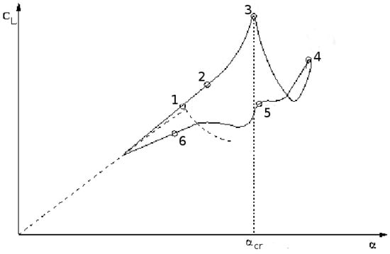
Figure 1.
Lift force of an airfoil pitching in the deep stall regime.
According to the present stall model, the vortex-shedding phenomenon is simulated as a self-excited oscillator of the Van der Pol-type equation when the aerodynamic incidence angle (or angle of attack ) keeps growing beyond the dynamic critical stall angle:
and by a damped oscillator when the flow is reattached:
where and are constants and t denotes time. The above equations have been simplified from the original modeling [9]; there is only one term proportional to in the second member of Equation (3). The Van der Pol equation was used successfully for vortex-shedding phenomenon past bluff bodies [23]. The modeling based on Equations (3) and (4) does not raise interest for other researchers, except a few [3,24], due to its non-linear behavior, which leads to numerical difficulties for comprehensive analysis codes.
The excess of the unsteady aerodynamic coefficient associated with the primary instability of the shear layer needs to be accounted for. Its contribution to the values of the aerodynamic coefficients is in the same order as from the DS vortex formation. In the model published previously [9], this effect is not clearly stated, but it is taken into account by the term , obtained from the response indicial approach. Such a term appears also in the ONERA–EDLIN model (the first term on the right-hand side of Equation (7) of [5]). The formulation in terms of the derivatives requires precise knowledge of the aerodynamic coefficients in the angle region in the neighborhood of the critical stall angle, which is not usually available. Therefore, it is proposed to delete the derivative component in the first equation governing the aerodynamic coefficients and instead consider the component of the aerodynamic coefficient governed by the following equation:
where:
where and are constants, denotes the separation function introduced by Beddoes [8], is the fluid velocity normal to the blade section and c is the chord length. The term provides a rapid variation to the aerodynamic coefficients at stall onset.
2.2. 3D Effects
The aerodynamics about the rotor blades are inherently 3D. The knowledge of 3D effects is still partial; there are ongoing studies based on experiments and CFD techniques. In comprehensive analysis, there are already semi-empirical corrections of 3D effects. Harris [25] is the first to propose corrections for radial flow based on sweep angles. This correction leads basically to the delay of the critical stall angle, but it leads to singular values for a sweep angle attaining 90; a more convenient value is proposed in [26]. This type of correction improves the predictions, but there remains the issue about the variable in play, the instantaneous sweep angle or some delayed value of the sweep angle [27].
In wind turbines, it is observed that the normal force is increased in inboard blade sections at normalized radial distance . Such effects are called “rotation effects” [28] and appear to be due to centrifugal and Coriolis forces [29,30]. Various corrections have been proposed for the aerodynamic coefficients [30], but none provides good correlation for the predictions with the experiments. In the present model, the following correction is proposed, limited to the normal force:
where is a constant and denotes a function decaying to zero as increases from :
The rotation effects can be determined by CFD analysis, as has been recently shown in wind turbines [31]. Therefore, the functions and can be evaluated. Incorporating the rotation effects into the polars leads to better improvement of the predictions by engineering models [32]. The issue is to replace the 2D polars by appropriate 3D polars.
There is also a new correction introduced in the stall model, associated with finite span blade effects. The phenomenon is described in Sitaraman’s thesis [33] as transonic tip relief effects appearing at the blade tip, leading to an important change of the pitching moment coefficient over a blade region of about 30% radius span. It is proposed to simulate the behavior of the pitching moment by the equations detailed in Appendix A. These equations are obtained based on semi-empirical considerations. However, it is possible to obtain the correct 3D behavior of from high-fidelity CFD simulation on swept wings with sweep angles in the range , typical values for helicopter flights.
2.3. Aerodynamic Correction for the High-Speed Flight
It is well known that comprehensive analysis fails to predict the air loads of rotors in high-speed flights. Bousman [34] raised the two main deficiencies of comprehensive analysis consisting of the predictions of the azimuthal position of the minimum of the lift force in the advancing side of the UH-60A and the under-prediction of the pitching moment, leading to the under-prediction of the pitch link loads. These two issues have been resolved with the coupling of comprehensive analysis with CFD techniques [1]. The same issues occur for the Rotor 7A, and they have been recently resolved [16,17]. The principal difference between the computation made with comprehensive stand-alone analysis and comprehensive analysis coupled with CFD techniques resides in the consideration of viscous effects by high-fidelity aerodynamics methods and ignored in low-order methods. In comprehensive analysis, the global flow field is evaluated with wake theories that are non-viscous theories. In order to take into account the viscous effect in the induced velocity, the following correction to the induced velocity is proposed:
where and are constants, denotes the rotation speed of the rotor, the azimuth and R the blade radius. The effects of such a correction on the induced velocity in the blade tip region can be visualized in Figure 2. Typical values for the 7A rotor are drawn for a high-speed flight at radius . Various corrections according to Equation (9) are applied:
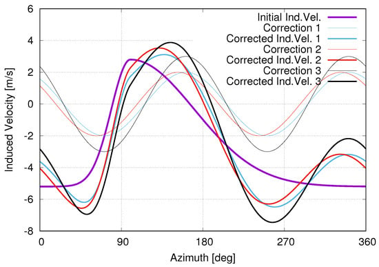
Figure 2.
Various corrections of the induced velocity (Ind. Vel.) and the corrected values for a typical high-speed flight at radius : Correction 1: , Correction 2: , Correction 3: .
- Correction 1:
- Correction 2:
- Correction 3:
The corrected values of the induced velocity based on these corrections are also represented in Figure 2. It is shown that the pair of values and contributes respectively to the azimuthal shift and the amplitude of the maximum of the induced velocity at around . Since the angle of aerodynamic incidence depends on the induced velocity, its minimum is also shifted, and therefore, the position of the minimum of the normal force goes towards a higher azimuthal value than the value of . The minimum value of the normal force also increases in amplitude.
It is possible to evaluate the correction of the induced flow with high-fidelity CFD numerical tools. In CFD analysis of helicopter rotors, fundamental quantities to CA analysis, such as induced velocity and angle of attack, are not currently extracted [2]. However, in wind turbines, researchers succeeded to elaborate the methodology for deriving the values of the angle of attack and induced velocity from CFD techniques [35,36].
2.4. Wind Tunnel Effects
Since the 7A rotor is placed in the Wind Tunnel S1 of ONERA, the aerodynamics about the rotor blades are perturbed by the presence of the rotor hub and the wind tunnel walls. The Aerodynamics Department of ONERA in 1993 (Internal report of Messrs. Alain Masson and Philippe Beaumier) elaborated a correction for accounting the hub and the wind tunnel walls, based on a surface panel method. It consists of a correction of the induced velocity for the nodes positioned on the blade sections. Figure 3 shows the values of the induced velocity normalized to the incoming flow velocity (according to the direction of the x axis) for the shaft angle = . Only a half azimuthal region is drawn; the other half can be deduced by symmetry. It can be noted that the direction of the induced velocity follows the deviations of the incoming flow by the rotor stand and the wind tunnel walls.
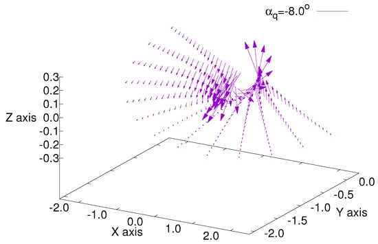
Figure 3.
Correction of the induced velocity due to the presence of the rotor stand and wind tunnel walls.
Another important effect introduced by wind tunnels concerns the effects of the Reynolds number. Indeed, the polars (look-up tables of aerodynamic coefficients) are provided for high Reynolds numbers, in the present case of the Rotor 7A for the ratio (M: Mach number) around eight million. It is well known that the aerodynamic coefficients depend on both Reynolds and Mach numbers [37], and it is difficult to separate each contribution. Usually, the Reynolds number effects decrease progressively as the Mach number increases; there is some critical value of the Mach number where the Reynolds number effects become insignificant. For practical considerations in comprehensive analysis, the effects of the Reynolds number are taken into account by corrections of the minimum drag coefficient, the lift-curve slope (versus the angle of attack) and the maximum of the lift coefficient [37,38]. The last physical quantity is associated with the critical stall angle ; when the angle of attack increases beyond , the lift force stops growing linearly. However, for such a variation of the angle of attack, the pitching moment coefficient and the drag coefficient change their behavior dramatically; decreases rapidly, while has an important increase. Therefore, it is more correct to take into account the Reynolds number effects in the critical stall angle that will affect all three aerodynamic coefficients, instead of the maximum of the lift coefficient alone. Additionally, the shape of the dependence of the aerodynamic coefficients with respect to the angle of attack varies also with the Reynolds number. However, such variation is ignored due to lack of experimental data.
As there is no available data for the airfoils OA209 and OA213 that compose the 7A blade, the data on the family of NACA airfoils are used [39]. It should be noted that the experiments used are made under the condition of a very small Mach number (≃0.06). The correction derived from these experiments is likely more important than observed in the wind tunnel, as for a high Mach number, it is expected that the effects of the Reynolds number decrease. The experimental values of the critical stall angles for the airfoils NACA0009, NACA0012, NACA0015 and NACA2412 are reported in Figure 4. These experimental values are fitted with the analytical expression of the following form:
where and are constants. For instance, for the airfoil NACA009, the values of the constants are:
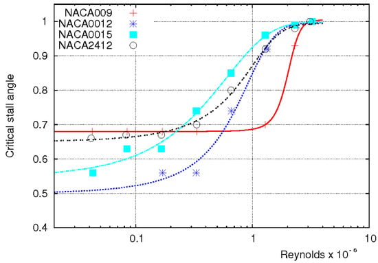
Figure 4.
Variation of the critical stall angle of various NACA airfoils with respect to the Reynolds numbers.
3. Implementation of the Stall Model
The Hopf bifurcation model is implemented as a module coupled to the comprehensive analysis code ROTOR of ONERA. The version of ROTOR used is a recently-developed code, with predicting capabilities for the whole helicopter, instead of an isolated rotor, as in the old version developed in the 1990s. The coupling is similar to the loose coupling between comprehensive analysis code and CFD code, but with different variables for the communication between the two codes. The comprehensive analysis code sends to the stall module the values of the aerodynamic conditions on the blade nodes during a rotation period, i.e., the aerodynamic incidence angle, the pitch angle and the fluid velocity adjacent to the blade. Based on these values, the stall module will calculate the values of the air loads (normal force, pitching moment, drag and radial forces) on the blade nodes for the whole rotation period. It iterates as many times as needed to attain a periodic solution. Since the aerodynamic forces are damped rapidly, it is sufficient to run the computation for three periods. However, for the particular study of flow delay with slow time delay, it was necessary to develop a method based on Poincaré maps for calculating the periodic solution [40]. The method relies on the fact that the periodic solution of the mechanical system, if it exists, will be a fixed point for the intersection of the trajectory of the mechanical system with the phase plane at times equal to multiple integers of the period. Accordingly, the problem is reduced to the search for a fixed point by Newton’s method.
The module is built for allowing the study of separate behaviors of the aerodynamic flow: quasi-steady “s”, unsteady without stall “u”, delayed flow “d”, flow with boundary-layer effects “b” and flow with vortex-shedding phenomenon “v”. It permits any combination of the various behaviors of the flow cited above. Such capabilities of the code permit separate validation of the parameters associated with each particular flow behavior. The general case with stall is determined by the option “udbv”.
As stated in Equation (2), the aerodynamic coefficients are decomposed into impulsive and circulatory components. The equations governing the unsteady behavior of the impulsive component are taken from [24]. based on thin airfoil theory. According to Johnson [24], the circulatory component is taken into account by the vortex wake model. The parameters for the delayed flow are provided by Beddoes [7]. The remaining unknown parameters are those characterizing the boundary-layer effects and the vortex-shedding phenomenon. To further simplify the model, only the equation governing the pitching moment for the behaviors of the boundary layer and for vortex shedding are solved; the components of the normal and drag forces are obtained by a multiplicative constant ( for the normal force and for the drag force). This choice is made from the analysis of the experiments on the NACA0012 airfoil. It could be changed according to the airfoil studied.
For any choice of the behavior of the aerodynamic flow, the aerodynamic forces on the blade sections of the rotor are governed by a system of ordinary differential equations (ODE). With the system of ODE involving the stall phenomena (Equations (3) and (4)), the flow equations will contain two different regimes, the first involving the unsteady flow without separation that varies slowly with time, while the regime involving the vortex-shedding phenomena has a rapid time-varying behavior. The system of ODE with two different behaviors with respect to time is qualified as “stiff”. There are two types of ODE solvers,“non-stiff” and “stiff”. The procedure for solving the system of ODE of the Hopf bifurcation model would be the use of the “non-stiff” solver before stall onset and the “stiff” solver at stall onset. Fortunately, there exists a solver specially developed for such circumstances, “LSODA” by Hindmarsh and Petzold in the 1980s [41,42], switching automatically from the non-stiff to the stiff solver whenever it is needed. The use of a unique solver “stiff” or “non-stiff” is not time efficient and may lead to numerical divergence.
The system of equations governing the mechanical behavior of the helicopter is non-linear with the addition of the equations governing the aerodynamic forces on the rotors (principal and tail). The search for an equilibrium solution is not an easy numerical task. The comprehensive analysis code ROTOR uses the solver hybrid of the package MINPACK [43]. It is based on a modification of Powell’s hybrid algorithm. Although developed in the 1980s, it is quite robust and has solving capabilities comparable to other solvers. Its principal weakness consists in the request of the initial solution not too far from the final solution; otherwise, it may diverge or take many iterations to converge.
4. Application to the Rotor 7A
In 1991, ONERA made a series of experiments in the Wind Tunnel S1 at Modane, France, on the Rotor 7A, to provide test cases for analysis. This rotor is articulated and composed of four blades with a rectangular planform and a radius of 2.1 m. The experiments were made in various flow configurations, from the attached flow regime to the stalled flow regime. A detailed description of the experiments was given in [16]. This study will consider three test conditions: high-speed Test Point 312, high-thrust Test Point 293 with light stall and high-thrust Test Point 596 with deep stall. The last configuration was obtained by slowing the rotor speed, from its nominal speed of about 1020 rpm to about 700 rpm. Many attempts to improve the analysis were made based on comprehensive analysis and then on comprehensive analysis coupled with CFD techniques [13,14,15]; only recently [16,17,18], the coupled analysis provides a good correlation of predictions with experiments for the test points 312 and 293. The improvement of recent coupled analysis results from a better structural beam model of the rotor blades and refinements in CFD techniques. The Test Point 596 with deep stall is not yet considered for coupled analysis.
The present computation is made for all of the test points cited above with the new version of comprehensive analysis code ROTOR of ONERA, equipped with the “Hopf bifurcation stall model”. For the test point 293, a calculation is also made with the comprehensive analysis HOST of Airbus Helicopters, for the illustration of the importance of an appropriate stall model. The global flow is simulated by the prescribed wake model; results based on uniform inflow or dynamic inflow models are not presented. The latter flow models do not provide good correlation of air loads in the tip region of the blade; such deficiency impacts the predictions in blade sections near the root. Calculations have been made under trim objectives of the experimental values of the rotor lift force , the rotor propulsive force and Modane flapping laws (zero lateral flapping and longitudinal cyclic equal to minus the longitudinal flapping angle). All of the computations are made with eight beam modes and eight harmonics.
4.1. High-Speed Test Point 312
The high-speed test point 312, characterized by the advance ratio and the lift force , was the case of choice for testing the capabilities of analysis in France and Germany. The comprehensive analysis code showed the same deficiencies in predictions, as for the UH-60A rotor treated with CA [34], i.e., the shift in the azimuthal position of the minimum of the normal force in the advancing side and the absence of positive and large values of the pitching moment in the first azimuthal quadrant for the blade sections in the tip region. These two deficiencies are shown in Figure 5 depicting the normal force and Figure 6 depicting the pitching moment at various blade sections, for the analysis made under the assumption of quasi-steady aerodynamics. The correction due to the wind tunnel effects creates mainly a bump for the normal force at the azimuth around for the blade sections of and and has no effect on the pitching moment. These features show that the correction of the induced velocity for wind tunnel effects (Figure 3) is in agreement with CFD simulation [16].
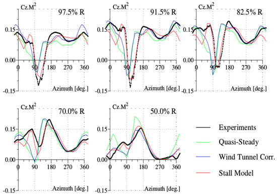
Figure 5.
Normal force for the high-speed test point of the Rotor 7A.
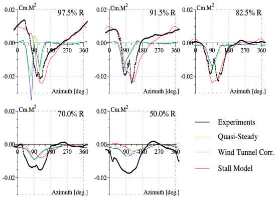
Figure 6.
Pitching moment for the high-speed test point of the Rotor 7A.
The values of the parameters used in the stall model chosen for the point 312 are given in Appendix B. There is a better correlation between the normal force computed with the stall model and the experimental results, especially the position of the minimum of the normal force at the end of the first azimuthal quadrant (Figure 5). However, the amplitude of the bump of the normal force at around is found exaggerated compared to experiments. The improvement in normal force predictions originates from the correction in induced velocity; their values are shown in Figure 7. The correction of the induced velocity implied by Equation (3) is not large; its main effect is to shift the position of the maximum (according to the axis convention of ROTOR, it may be the minimum for the other convention) of the induced velocity at around the azimuth of to a higher value.
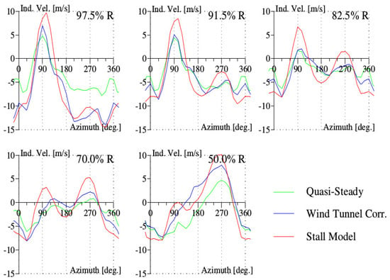
Figure 7.
Induced velocity (Ind. Vel.) for the high-speed test point of the Rotor 7A.
The pitching moment values given by experiments and by simulation are depicted in Figure 6. The improvement of the correlation of simulation with experiments at the blade sections near the blade tip, and , is due to the accounting of the transonic tip relief effects on the pitching moment. In the inner blade sections, and , the simulated values of are quite small compared to the experimental values. In fact, CFD simulation [16] showed that the unexpected high values of experiments are the consequences of the pressure integration based on the small number and the spatial location of the pressure sensors equipping the rotor blade sections.
The improvement brought by the stall model can be also visualized on the vibratory loads; these loads represent the dominant source of the helicopter vibrations. They correspond to the harmonics 3–8 of the normal force, for the 7A rotor with four blades. The stall model provides a better correlation with experiments for all of the outboard sections up to the section , where the predictions are degraded (see Figure 8).
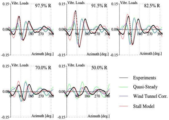
Figure 8.
Vibratory loads (Vibr. Loads) for the high-speed test point of the Rotor 7A.
The rotation effects are assumed to provide improved predictions of the normal force at inboard blade sections, near the rotor hub. Unfortunately, measurements on the Rotor 7A were limited to inboard section at the radius of . Nonetheless, it is possible to estimate indirectly the corrections due to rotation effects. Indeed, to get the trim on the global lift of the rotor, the normal forces have to be equilibrated on all of the blade sections. Since rotation effects provide more amplitude for the normal forces at inboard sections, the normal forces at outboard sections are submitted to a decrease in order to maintain the equilibrium; particularly, at the section , the normal force at the azimuth of around decreases to attain more negative values.
The improvements of air loads lead to improved predictions of the structural loads of flap and chord bending moments and torsion moment (Figure 9). The measurements are only shown for two blade sections; the third exploitable measurement obtained at the more outboard blade section (at for the flap bending moment and the torsion moment, respectively, at for the chord bending moment) is very similar to the nearest inboard blade section measurement and is not shown in the figure. For the torsion moment, the stall model provides the phase shift at the end of the first azimuthal quadrant. However, the predicted amplitude is about higher than in experimental results, and the predicted harmonic component in 5/rev (5 per revolution) is lower than in the experiments. For the chord bending moment, the prediction is not only higher in amplitude than experimental results, but also contains four peaks instead of three as in the experiments. The flap bending moment is better predicted by the stall model for the blade section at than at . The predictions of the structural loads are clearly improved by the aerodynamics modeling, but lack the precision features of coupled analysis based on high-fidelity CFD techniques [18]. One particular remark about the chord bending moment prediction is that the amplitude predicted by the French CA codes (ONERA, Airbus Helicopters) is much higher than in experiments, whereas the American code RCASprovides the correct amplitude [18].
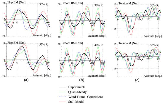
Figure 9.
Structural loads for the high-speed test point of the Rotor 7A: (a) flap bending moment; (b) chord bending moment; (c) torsion moment.
The rotor control angles and the power predictions are also examined. Table 1 lists the values of the rotor control angles from experiments and from calculations made with quasi-steady aerodynamics and the stall model, respectively. The values of the shaft angle and the collective pitch angle calculated with both aerodynamic options are reasonably correct. The values of the longitudinal and lateral cyclic pitch angles calculated deviate from the experiments. This is a surprising result, compared to the results obtained with the older version of ROTOR, under quasi-steady aerodynamics, denoted in Table 1 as “QS aero. 2” (“QS aero. 1” with the present version of ROTOR); particularly, the lateral cyclic pitch angle was better predicted. During the course of this study concerned with the implementation of the stall model in the comprehensive analysis code, the author has not enough time to debug this feature in the present version of ROTOR. The prediction of power P is overestimated from the test values under quasi-steady aerodynamics; but it is slightly underestimated with the stall model.

Table 1.
High-speed Flight 312: control angles and power ( QS aero.: quasi-steady aerodynamics).
4.2. High-Thrust Test Point 293
This test point is characterized by the advance ratio and the lift force . The predictions of this test flight have been recently improved by coupled analysis of comprehensive analysis with CFD techniques, by teams at the US Army and ONERA [16,18]. However, no computation based on stand-alone comprehensive analysis with reasonable correlation between predictions and experimental results has been published. Computations made so far fail to detect stall onset in this test point. The cause is due to Reynolds number effects, responsible for decreasing the critical stall angle, as shown previously in Figure 4. Based on experiments on the family of NACA airfoils, it is possible to correct the critical stall angle for each blade section on the Blade 7A. With such a correction, the comprehensive analysis predicts the appearance of stall phenomenon for this test point. The parameters of the stall model for this test point are detailed in Appendix B. Another computation is made with the comprehensive analysis HOST, developed by Airbus Helicopters, but with no stall model and no Reynolds number correction.
The normal force is shown in Figure 10 for various blade sections. The first minimum of the normal force at the azimuth around is captured by the stall model, with the correction of the induced velocity (Equation (9)). The minimum at around the azimuth of associated with the stall phenomenon is captured, although not very clearly for the blade section at . There is a singular behavior of the normal force at the azimuth of around , namely a peak that is very pronounced at the blade tip sections. The peak amplitude is much greater if the slope of the lift force with respect to the angle of attack is chosen to be given by the relationship of Prandlt–Glauert (equal to , instead of the value used in Appendix B. Coupled analysis with CFD techniques indicates a very unstable behavior of aerodynamics at this azimuthal position, but does not provide a precise explanation [16]. The predicted values of the pitching moment in Figure 11 show negative values at the azimuth of around for all of the blade sections; these values are associated with stall onset. HOST, lacking accounting for Reynolds number effects, is unable to detect stall onset. Note that the predicted stall azimuthal region is larger than in the experiments, and the stall onset predicted occurs at a lower azimuth than in the experiments. The correction of the Reynolds number effects appears to be more important than observed in the experiments.
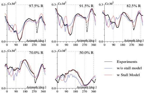
Figure 10.
Normal force for the high-thrust Test Point 293 of the Rotor 7A.
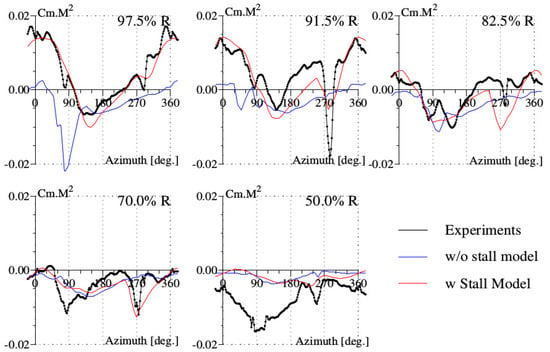
Figure 11.
Pitching moment for the high-thrust test point 293 of the Rotor 7A.
The vibratory loads are shown in Figure 12; there is improvement from the stall model, but the predictions deteriorate very quickly, starting at the blade section .
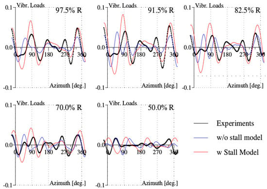
Figure 12.
Vibratory loads (Vibr. Loads) for the high-thrust test point 293 of the Rotor 7A.
The structural loads are shown at only two blade sections in Figure 13; the third exploitable measurement at the outboard blade section is not shown for the same reason as for the high-speed test point. The predictions of the flap bending moment are improved by the stall model. The values of the chord bending moment predicted are not much affected by the stall model. The torsion moment is better predicted by the stall model, although the negative peak at is predicted at lower azimuth; this characteristic is associated with the early prediction of stall onset for the pitching moment.
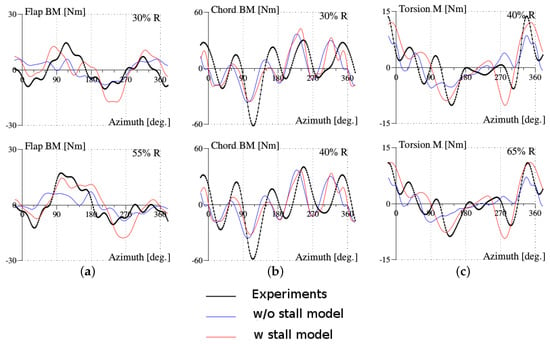
Figure 13.
Structural loads for the high-thrust test point 293 of the Rotor 7A: (a) flap bending moment; (b) chord bending moment; (c) torsion moment.
As for the high-speed test point, the control angles given by the calculations, shown in Table 2, do not have a good correlation with the experiments. The value of the collective pitch angle calculated by HOST is higher than the experiments by about , whereas ROTOR predicts a smaller value. This feature is associated with the capabilities of the respective CA to provide enough lift force requested by the trim conditions. HOST needs a high value of collective pitch to provide enough lift force. Due to a too strong correction of the Reynolds number effects, ROTOR provides a larger stall range than in the experimental conditions. As for the previous test point, the cyclic pitch angles predicted by ROTOR are lower than the experimental values. For the power prediction, this code predicts a high value of about 11%, compared to the experiments.

Table 2.
High-thrust Flight 293: Control angles and power given by experiments and computations without Stall Model ( w/o St. Mod.) and with Stall Model ( w Stall Model).
4.3. High-Thrust Test Point 596
The test point 596 is characterized by the advance ratio and the lift force , a quite high value. This test point was obtained by slowing the rotor speed from its nominal speed of 1020 rpm to about 700 rpm. Valid air load measurements are unfortunately obtained only for two blade sections, and . However, measured structural loads are exploitable at four blade sections, while for the previous test points, there are only valid measurements at three blade sections. The computation is carried out under fixed control settings and trimmed control settings. The parameters for the stall model are chosen exactly the same as for the previous test point with light stall. Comprehensive analysis code does not usually succeed [11] to obtain numerical convergence at such high values of the lift force, and the calculation is then carried out under fixed control settings, given by experimental values. The comprehensive analysis code ROTOR equipped with the Hopf bifurcation model succeeds to provide the converged numerical solution for both control settings options. For air loads, the calculations provide a reasonably good correlation with the experiments (Figure 14). The predicted lift force with trimmed conditions provides better results than with fixed control settings; the vibratory loads reflect also such a correlation behavior (Figure 14). The discrepancies between predictions and experiments of the normalized lift force are most important in the fourth azimuthal quadrant for the blade section . The prediction of the pitching moment captures the negative peak in the third azimuthal quadrant, associated with stall onset (Figure 14).
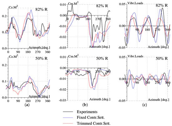
Figure 14.
Air loads for the high-thrust test point 596 of the Rotor 7A under conditions of fixed and trimmed control settings (Contr. Sett.): (a) normal force; (b) pitching moment; (c) vibratory loads.
The calculation under trimmed conditions provides better predictions for the flap bending moment (Figure 15); it captures the experimental shape waveform except for the outboard section at . For this test point with the important influence of dynamic stall, the amplitude of the chord bending moment predicted (Figure 16) is in agreement with experiments. The number of oscillations is visibly the same as in the experiments. The predicted values of the torsion moment follow the waveform of the experimental results (Figure 17). However, the number of oscillations is greater than observed experimentally. This feature will need more analysis.
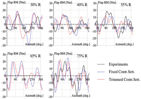
Figure 15.
Flap bending moment (BM) for the high-thrust test point 596 of the Rotor 7A.
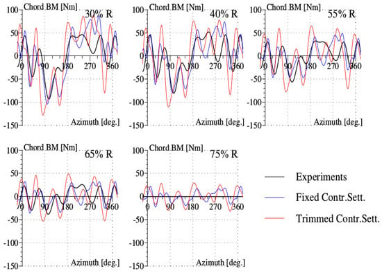
Figure 16.
Chord bending moment (BM) for the high-thrust test point 596 of the Rotor 7A.
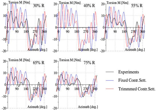
Figure 17.
Torsion moment (M) for the high-thrust test point 596 of the Rotor 7A.
The predictions of the control angles, listed in Table 3, are in good agreement with the experiments only for the pitch collective angle. As for previous test points, the predicted values of cyclic pitch angles are not in good correlation with the experiments, but in this test point, additionally, the predicted value of the shaft angle deviates more from the experiments. The prediction power is very large compared to experiments, of about 40% of the overestimation. This discrepancy is due to the too strong correction of the Reynolds number effects, which generates a larger azimuthal range for the dynamic stall phenomenon.

Table 3.
High-thrust Flight 596: control angles and power under fixed and trimmed control settings (C.T.).
Remark 1.
The importance of the stall phenomenon can be seized through the examination of the air loads and structural loads of the three test points. As the aerodynamics about the 7A rotor get deeper in the stall regime, the pitching moment is observed to rise rapidly with an increasing amplitude in the retreating azimuthal region. This quantity is the key component influencing the structural loads, since it excites the structural dynamic behavior of the blades. The torsion moment behavior follows more closely the pitching moment (see Figure 9, Figure 13 and Figure 17) as dynamic stall grows in importance. In the meantime, the flap and chordwise bending moments acquire a richer harmonic component (see Figure 9, Figure 13, Figure 15 and Figure 16).
5. Summary and Conclusions
To attain reasonable agreement of the predictions of the comprehensive analysis with experiments on the Rotor 7A, various issues have been solved at two different levels, physics modeling of aerodynamics for capturing the dynamic stall phenomenon and 3D effects and code implementation for ensuring numerical convergence:
- The action of modeling aerodynamics has been made at the level of the global flow, outside of the stall model, for the accounting of the extreme aerodynamic condition of the high-speed flight. The proposed correction can be checked independently by high-fidelity CFD techniques. The methodology for the extraction of the induced velocity and the angle of attack has been established in wind turbines.
- The Hopf bifurcation stall model has been revised to emphasize the boundary-layer effects accompanying the formation of the dynamic stall vortex. This phenomenon is responsible for about half of the important variation of the pitching moment at stall onset. This stall model is the only one to treat the vortex-shedding phenomenon as a non-linear effect governed by ordinary differential equations. The number of parameters of the model is limited to those contained in Equations (3)–(6), for characterizing the vortex-shedding phenomena and the boundary-layer effects. The determination of the parameters of the stall model requires some expense in CFD simulation or in experimentation, but once their values are established, they could be used for a large variety of test configurations.
- Comprehensive analysis uses look-up tables for the values of aerodynamic coefficients and, thus, is a time-efficient means for the predictions of the aeromechanical behavior of the rotor. These tables are up to now 2D values of aerodynamic coefficients. If appropriate 3D corrections are made on these tables, based on experiments or CFD computation, the predictions of CA will be improved. Such a procedure was made for rotation effects in wind turbines. The main issue is therefore to replace the 2D polars by appropriate 3D polars.
- The procedure for the implementation of the “Hopf bifurcation model” to the comprehensive analysis code of ONERA has been presented. The numerical code established is robust and allows convergence in the deep-stall test point of the Rotor 7A.
- The application of the comprehensive analysis code equipped with the stall model has been illustrated on three test points of the Rotor 7A carried out in the Wind Tunnel S1 of ONERA, involving high-speed and high-thrust test points. For wind tunnel experiments, it was necessary to make corrections for the aerodynamic tunnel environment, rotor stand and wind tunnel walls, as well as corrections for Reynolds number effects. For all test points, the predictions of air loads are in reasonable agreement with experiments and require about 30 min on a PC for stalled test points and less for the high-speed test point. Such test cases request weeks of computation for coupled analysis involving CFD techniques, on multiprocessor machines. Improvement of air load predictions leads to improved predictions of structural loads.
Acknowledgments
The author would like to express his thanks to Mr. Didier Petot (retired scientist from ONERA) for his explanations about the use and the architecture of the comprehensive analysis code ROTOR of ONERA. He is also grateful to the anonymous referee for indicating the references that established the methodology of extracting the values of the angle of attack and induced velocity from CFD analysis in wind turbines.
Conflicts of Interest
The author declares no conflict of interest.
Abbreviations
The following abbreviations are used in this manuscript:
| aerodynamic coefficients (i = 1: lift; i = 2: pitching moment, i = 3: drag) | |
| in Regime 1 of attached flow | |
| in Regime 2 of separated flow | |
| M | Mach number |
| Reynolds number | |
| aerodynamic incidence angle or angle of attack | |
| critical stall angle | |
| normalized radial distance | |
| revolution | |
| R | blade radius |
| sweep angle, expressed in degrees | |
| Contr. Sett. | control settings |
| BM | bending moment |
| w/o | without |
| w | with |
Appendix A. 3D Pitching Moment Coefficient
As described in Sitaraman’s thesis [33], transonic tip relief effects appear at the blade tip, leading to an important change of the pitching moment coefficient over a blade region of about a 30% radius span. It is proposed to simulate the behavior of the pitching moment by the following equations:
where denotes a function decaying rapidly at the blade tip, and decays towards inboard blade sections:
The 2D values of the pitching moment coefficient decrease rapidly to zero near the blade tip, while the values extend to the inboard region of the blade over a length of about 0.10 . The following equations govern the behavior of :
where denotes the aerodynamic incidence angle, M the Mach number, the sweep angle in degrees and and are constants. The functions g and h are defined by the following relations:
According to the analytical expression for , the effects increase with Mach number, but remain limited when M exceeds 0.7. The transonic tip relief effects depend also on the sweep angle; the dependence follows the law in “tanh” that limits the effects when the sweep angle exceeds 20. The variation with the aerodynamic incidence angle is suggested by the values computed by Sitaraman. The additional component that depends on sweep angles is needed to create the asymmetry, with respect to the azimuth, of the values of the normal force about its minimum value at around the azimuth of 100.
Appendix B. Values of the Parameters Used for the Test Points
The values of the parameters chosen for the high-speed point 312 are the following:
To create the shift of the azimuthal position of the minimum of the normal force, the correction of the induced velocity according to Equation (9) is used with the following values of the parameters:
The parameter values for the high-thrust point 293 are derived from those of the high-speed point by multiplying by the ration of advance ration, i.e., 0.3/0.4. For the high-thrust point 596 with deep stall, these values remain the same.
The value of the parameter for rotation effects is:
The values of parameters related to vortex-shedding phenomenon and boundary-layer effects are chosen as:
There is an additional tip correction for the drag coefficient, similar to the correction made for the lift coefficient when the global flow is modeled as uniform. The correction of the Reynolds number effects is limited to the minimum of the drag only, not to the total drag, as in the recent communication [44].
The lift slope with respect to the angle of attack is governed by the following equation that fits the values for the Airfoil SC1095:
References
- Potsdam, M.; Yeo, H.; Johnson, W. Rotor Airloads Prediction Using Loose Aerodynamic/Structural Coupling. J. Aircr. 2006, 43, 732–742. [Google Scholar] [CrossRef]
- Ormiston, R.A. Revitalizing Advanced Rotorcraft Research and the Compound Helicopter, 35th AHS Alexander A. Nikolsky Honorary Lecture. J. Am. Helicopter Soc. 2016, 61, 1–23. [Google Scholar] [CrossRef]
- Snel, H. Review of the Present Status of Rotor Aerodynamics. Wind Energy 1998, 1, 46–69. [Google Scholar] [CrossRef]
- Tran, C.T.; Petot, D. Semi-empirical model for the dynamic stall of airfoils in view of the application to the calculation of responses of a helicopter blade in forward flight. Vertica 1981, 5, 35–53. [Google Scholar]
- Petot, D. Differential Equation Modeling of Dynamic Stall. Rech. Aérosp. 1989, 5, 59–72. [Google Scholar]
- Peters, D.A. Toward a Unified Lift Model for Use in Rotor Blade Stability Analyses. J. Am. Helicopter Soc. 1985, 30, 32–42. [Google Scholar] [CrossRef]
- Beddoes, T.S. Representation of Airfoil Behavior. Vertica 1983, 7, 183–197. [Google Scholar]
- Leishman, J.; Beddoes, T. A semi-empirical model for dynamic stall. J. Am. Helicopter Soc. 1989, 34, 3–17. [Google Scholar] [CrossRef]
- Truong, K.V. A 2-D dynamic stall model based on Hopf bifurcation. In Proceedings of the 19th European Rotorcraft Forum, Cernobbio, Italy, 14–16 September 1993. [Google Scholar]
- Nguyen, K.; Johnson, W. Evaluation of Dynamic Stall Models with UH–60A Airloads Flight Test Data. In Proceedings of the AHS 54th Annual Forum, Washington, DC, USA, 20–22 May 1998. [Google Scholar]
- Yeo, H. Calculation of Rotor Performance and Loads Under Stalled Conditions. In Proceedings of the AHS 59th Annual Forum, Phoenix, AZ, USA, 6–8 May 2003. [Google Scholar]
- Petot, D.; Bessone, J. Numerical Calculation of Helicopter Equations and Comparison with Experiment. In Proceedings of the 18th European Rotorcraft Forum, Avignon, France, 15–18 September 1992. [Google Scholar]
- Pahlke, K.; van der Wall, B.G. Chimera Simulations of Multibladed Rotors in High-Speed Forward Flight with Weak Fluid-Structure-Coupling. In Proceedings of the 29th European Rotorcraft Forum, Friedrichshafen, Germany, 16–18 September 2003. [Google Scholar]
- Beaumier, P.; Costes, M.; Rodriguez, B.; Poinot, M.; Cantaloube, B. Weak and strong coupling between the elsA CFD solver and the HOST helicopter. In Proceedings of the 31st European Rotorcraft Forum, Florence, Italy, 13–15 September 2005. [Google Scholar]
- Pomin, H.; Wagner, S. Aeroelastic Analysis of Helicopter Rotor Blades on Deformable Chimera Grids. J. Aircr. 2004, 41, 577–584. [Google Scholar] [CrossRef]
- Ortun, B.; Potsdam, M.; Yeo, H.; Truong, K.V. Rotor Loads Prediction on the ONERA 7A Rotor Using Loose Fluid/Structure Coupling. In Proceedings of the AHS 72nd Annual Forum, West Palm Beach, FL, USA, 17–19 May 2016. [Google Scholar]
- Surrey, S.; Ortun, B.; Truong, K.V.; Wienke, F. Advanced modeling of the 7A structural rotor blade dynamics. In Proceedings of the AHS 72nd Annual Forum, West Palm Beach, FL, USA, 17–19 May 2016. [Google Scholar]
- Yeo, H.; Potsdam, M.; Ortun, B.; Truong, K.V. High-Fidelity Structural Loads Analysis of the ONERA 7A Rotor. In Proceedings of the 42nd European Rotorcraft Forum, Lille, France, 5–8 September 2016. [Google Scholar]
- Ericsson, L.E.; Reding, J.P. Fluid mechanics of dynamic stall part I. Unsteady flow concepts. J. Fluid Struct. 1988, 2, 1–33. [Google Scholar] [CrossRef]
- Jumper, E.J.; Stephen, F.J. Toward Unsteady Lift Augmentation: An Assessment of the Role of Competing Phenomena in Dynamic Stall. In Proceedings of the Workshop II on Unsteady Separated Flow, Frank J. Seiler Research Laboratory, US Air Force Academy, CO, USA, 28 July 1988. Report FJSRL-TR-88-0004. [Google Scholar]
- Mulleners, K.; Raffel, M. Dynamic stall development. Exp. Fluids 2013, 54, 1469–1477. [Google Scholar] [CrossRef]
- Choudhry, A.; Leknys, R.; Arjomandi, M.; Kelso, R. An insight into the dynamic stall lift characteristics. Exp. Therm. Fluid Sci. 2016, 58, 188–208. [Google Scholar] [CrossRef]
- Blevins, R.D. Flow-Induced Vibration, 2nd ed.; Van Nostrand Reinhold: New York, NY, USA, 1990. [Google Scholar]
- Johnson, W. Rotorcraft Dynamics Models for a Comprehensive Analysis. Proceeding of the AHS 54th Annual Forum, Washington, DC, USA, 20–22 May 1998. [Google Scholar]
- Harris, F.D.; Tarzanin, F.J.; Fisher, R.K. Rotor High Speed Performance, Theory vs Test. J. Am. Helicopter Soc. 1970, 15, 35–44. [Google Scholar] [CrossRef]
- Barwey, D.; Peters, D.A. Modeling of Radial–Flow Stall Effects for Rotor Dynamics. In Proceedings of the Sixth International Workshop on Dynamics and Aeroelastic Stability Modeling of Rotorcraft Systems, UCLA, Los Angeles, CA, USA, 8–10 November 1995. [Google Scholar]
- Leishman, J. Modeling Sweep Effects on Dynamic Stall. J. Am. Helicopter Soc. 1989, 34, 18–29. [Google Scholar]
- Himmelskamp, H. Profile Investigations on a Rotating Airscew. Ph.D. Thesis, University of Göttingen, Göttingen, Germany, 1945. [Google Scholar]
- Snel, H.; Houwink, R.; Bosschers, J. Sectional Prediction of Lift Coefficients on Rotating Wind Turbine Blades in Stall; Netherlands Energy Research Foundation: Petten, The Netherlands, 1994. [Google Scholar]
- Breton, S.P.; Coton, F.N.; Moe, G. A Study on Rotational Effects and Different Stall Delay Models Using a Prescribed Wake Vortex Scheme and NREL Phase VI Experiment Data. Wind Energy 2008, 11, 459–482. [Google Scholar] [CrossRef]
- Bangga, G.; Lutz, T.; Jost, E.; Krämer, E. CFD studies on rotational augmentation at the inboard sections of a 10 MW wind turbine rotor. J. Renew. Sustain. Energy 2017, 9, 023304. [Google Scholar] [CrossRef]
- Guntur, S.; Sørensen, N.N.; Schreck, S.; Bergami, L. Modeling dynamic stall on wind turbine blades under rotationally augmented flow fields. Wind Energy 2016, 19, 383–397. [Google Scholar] [CrossRef]
- Sitaraman, J. CFD Based Unsteady Aerodynamic Modeling for Rotor Aeroelastic Analysis. Ph.D. Thesis, Department of Aerospace Engineering, University of Maryland, College Park, MD, USA, 2003. [Google Scholar]
- Bousman, W.G. Putting the Aero Back Into Aeroelasticity. In Proceedings of the Eighth ARO Workshop on Aeroelasticity of Rotorcraft Systems, University Park, PA, USA, 18–20 October 1999. [Google Scholar]
- Shen, W.Z.; Hansen, M.O.L.; Sørensen, J.N. Determination of the angle of attack on rotor blades. Wind Energy 2009, 12, 91–98. [Google Scholar] [CrossRef]
- Guntur, S.; Sørensen, N.N. An evaluation of several methods of determining the local angle of attack on wind turbine blades. J. Phys. Conf. Ser. 2014, 1, 012045. [Google Scholar] [CrossRef]
- Yamauchi, G.K.; Johnson, W. Trends of Reynolds Number Effects on Two-Dimensional Airfoil Characteristics for Helicopter Rotor Analysis; NASA TM-84363; National Aeronautics and Space Administration: Hampton, VA, USA, 1983.
- McCroskey, W.J. A Critical Assessment of Wind Tunnel Results for the NACA 0012 Airfoil; NASA TM-100019; National Aeronautics and Space Administration: Hampton, VA, USA, 1987.
- Jacobs, E.N.; Sherman, A. Airfoil Section Characteristics as Affected by Variations of the Reynolds Number; NACA Report 586; National Advisory Committee for Aeronautics: Hampton, VA, USA, 1937.
- Parker, T.S.; Chua, L.O. Practical Numerical Algorithms for Chaotic Systems; Springer Inc.: New York, NY, USA, 1989. [Google Scholar]
- Hindmarsh, A.C. A Systematized Collection of ODE Solvers. In IMACS Transactions on Scientific Computation; North-Holland: Amsterdam, The Netherlands, 1983; Volume 1, pp. 55–64. [Google Scholar]
- Petzold, L.R. Automatic selection of methods for solving stiff and nonstiff systems of ordinary differential equations. SIAM J. Sci. Statist. Comput. 1983, 4, 136–148. [Google Scholar] [CrossRef]
- Moré, J.J.; Garbow, B.S.; Hillstrom, K.E. User Guide for MINPACK-1; Report ANL-80-74; Argonne National Laboratory: Argonne, IL, USA, 1980.
- Truong, K.V. Modeling Aerodynamics for Comprehensive Analysis of Helicopter Rotors. In Proceedings of the 42nd European Rotorcraft Forum, Lille, France, 5–8 September 2016. [Google Scholar]
© 2017 by the author. Licensee MDPI, Basel, Switzerland. This article is an open access article distributed under the terms and conditions of the Creative Commons Attribution (CC BY) license (http://creativecommons.org/licenses/by/4.0/).