1. Introduction and Background
The present study develops and tests a modular design method for small solid-propellant (SP) rockets utilizing the benefits of additive manufacturing (AM) technologies during design and fabrication. The design process thus developed will take advantage of the many benefits offered by AM to produce excellent rocket airframe designs while modularizing the system as much as possible. For the purposes of this study, a SP rocket will be defined as being an aircraft that uses a fast-burning solid propellant for motion, aerodynamic fins as control surfaces, and a strictly atmospheric range domain. The aircraft can fly either vertically or horizontally, may or may not have active control, and will always carry a small payload. Examples of such aircraft are legion; sounding rockets for carrying small scientific instruments [
1,
2], military hardware (particularly air-to-air missiles, ballistic missiles and missile defense [
3,
4,
5], atmospheric booster stages on some orbital vehicles [
6,
7], model rockets for education, research, and entertainment [
8,
9], and controlled avalanche triggering devices [
10].
Modularization is a product design technique in which the system is divided into subsystems or modules, which can be designed and manufactured independently and, ideally, used in several different systems. Examples of modular products abound, from furniture to construction equipment, production tooling, office cubicles, and even homes. The basic reason for the modularization of products is to overcome design and production issues, control the product lifecycle more effectively, produce more flexible product lines, and to gain more output from invested time and resources [
11,
12,
13].
To best accomplish these goals, several specific objectives must be developed for the product in design [
14,
15]. In informal terms, these are:
Design tasks should be done by teams of specialists to facilitate efficient development;
Customize and improve the production and assembly process for the subsystems;
Standardize every possible aspect of the system or subsystem;
Consider testing, maintenance, and repair requirements when designing the architecture;
Design products such that individual parts and subsystems can be easily upgraded;
Design products to be easily reconfigurable for different missions;
Design products such that disassembly and recycling at end-of-life is simplified;
Design products that have a specific core mission but that are easily customized by the user.
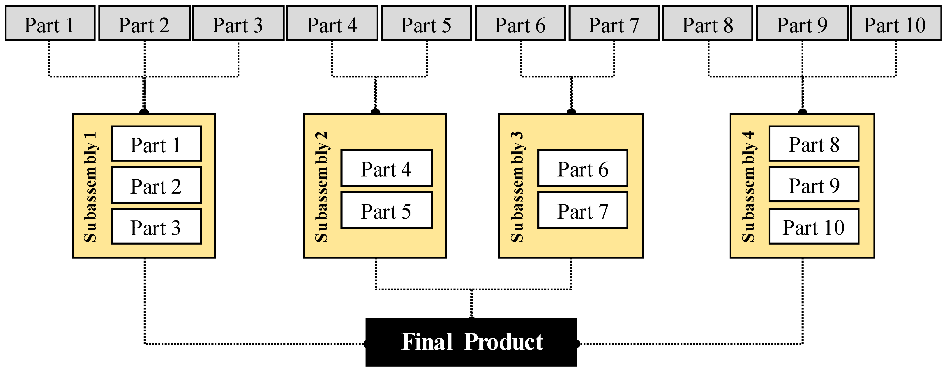
Traditionally, these objectives are met by the design and production of independent subsystems, each containing various parts of the system (
Figure 1).
The main issue with this approach is the problems with integration and communication between the various subsystems once they are assembled. Each subsystem would traditionally be designed by a team of specialists, each team using a slightly different architecture and control technique [
15]. Many systems engineering (SE) product lifecycle engines, such as the SE Engine used by the US National Aeronautics and Space Administration (NASA) [
16] and the Systems-of-Systems approach used by the US Missile Defense Agency (MDA) [
17], develop sophisticated and complex techniques for dealing with these integration problems.
A more effective, if yet not fully proven, technique for modularization is the integration-of-functions method, in which advanced manufacturing techniques such as AM can be used to produce multi-function parts [
18,
19]. This reduces or eliminates the need for using subsystems to gain the benefits of modularization. This technique also removes most or all the inherent integration problems encountered with subsystems; it is well known that most systems failures happen at interfaces, so eliminating interfaces raises the reliability and quality of the entire system [
20,
21].
Objections could be raised to this, as the technique removes standardization from the modularization process and requires all the system components to be specialized. This objection is eliminated by one of the basic characteristics of AM technologies, mass customization [
22,
23]. Since AM does not require any special tooling to produce parts and the parts are infinitely customizable within the design software [
24], a supply chain of readily available on-the-shelf parts is not necessary.
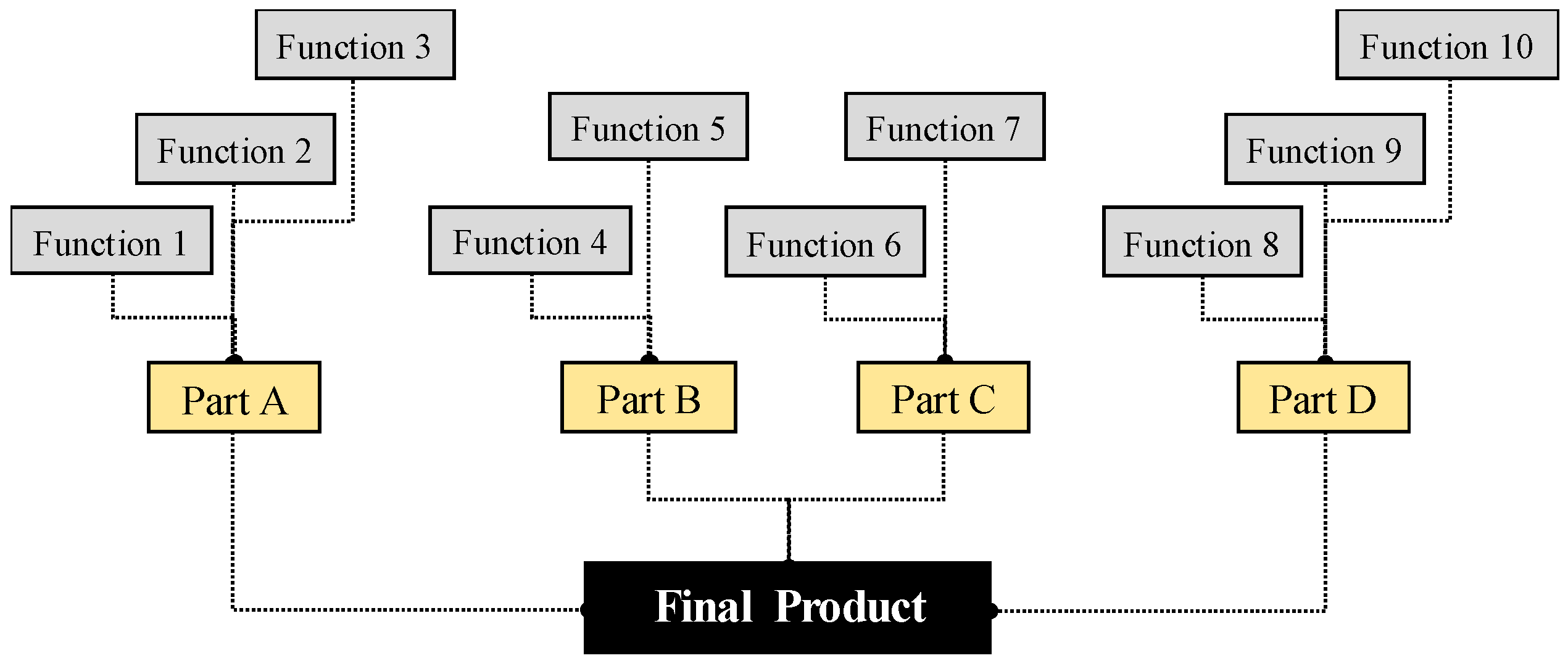
Figure 2 shows graphically how the modularization concept is modified by the use of AM.
While it is sometimes practical to print final products as single parts, this suppresses the other benefits of modularization, particularly those offered by Goals 4–8 (see above); systems fabricated in this way usually will be throw-away products that are not meant to be repaired or upgraded. Therefore, it is assumed for most products that would be modularized that the subsystem level is the highest level at which it is practical to combine functions into single parts. This has introduced the concept of feature cataloging [
25], contrasted with the old method of part or subsystem cataloging.
2. Materials and Methods I: Modular Additive Manufacturing (AM)-Based Design Methodology
This section expands on the previously discussed topic of product modularity and develops the basic model for a modular AM-based design methodology. There is not yet a clear and universally accepted general definition of “product modularization” [
26]; therefore, in the context of the present study and previously discussed research, the authors offer the following definition for a traditional system:
Product modularization is the process of decomposing a complex system into standardized and more easily manageable subsystems with five major characteristics:
- ▪
The subsystems are composed of a high percentage of standard off-the-shelf components;
- ▪
The subsystems are easily serviceable and recyclable;
- ▪
The subsystem itself or any of its components can be replaced or upgraded by the user at will;
- ▪
The system has a core mission, but the specific configuration of subsystems allows it to accomplish more than one mission;
- ▪
The modular system offers time or cost savings or another significant benefit to the user, compared with a non-modular system for the same task.
As described previously, AM technologies allow the integration of functions within a design. While traditional modularization mainly involved the collection of similar or complementary parts into groups [
27], the integration of functions involves the manufacturing of more complex parts instead of subsystems. This would seem counterintuitive to the casual observer, but the introduction of AM technologies and infinite tool-less customization into the equation allows this idea to be effective. Lack of customization within modularizations is sometimes a hard price to pay for specialized systems, as the use of one-off parts is highly discouraged [
27].
All AM parts are, by definition, one-off parts; complex and simple, standardized parts are equally difficult to produce. However, it is important to maintain system flexibility as much as possible; AM allows almost infinite flexibility during design and fabrication, but none in the field. From this knowledge, it is clear that a modularity-based design process for additively manufactured products requires a marriage of both modularity principles and traditional non-modular design principles. Each of the authors’ modularization principles discussed above are affected by this:
- ▪
Standardization of components: An AM-based methodology eliminates standardization almost completely; all the components used are theoretically customized. In a non-AM system, this could give the optimal design for a particular application but would be prohibitively expensive. AM offers the optimization benefits without the high cost, but does not eliminate the standardization problem.
- ▪
Serviceability and recyclability of the system components: Since subsystems are replaced by single complex parts, serviceability of the subsystems is nearly impossible. However, this may not be a large problem if the complex parts are inexpensive enough such that they are easily and cheaply replaced. The savings in manufacturing and assembly cost from using complex parts instead of subsystems will likely offset the non-serviceability of the components. Recyclability will most likely dramatically improve with the use of AM, as the parts will likely be made from a single material.
- ▪
User customizability: Producing a modular system that the customer can modify at will is much more difficult using AM, as fewer parts means less on-the-go customizability. However, the user could have much more input into the design at the beginning, reducing the desire and need to customize.
- ▪
Core mission: While most integrated AM-made products will likely be less flexible for the user, the increased user input during design will provide the best possible benefit to the user and the lower cost likely means that the user could afford a wider range of products, reducing the need for a do-all product.
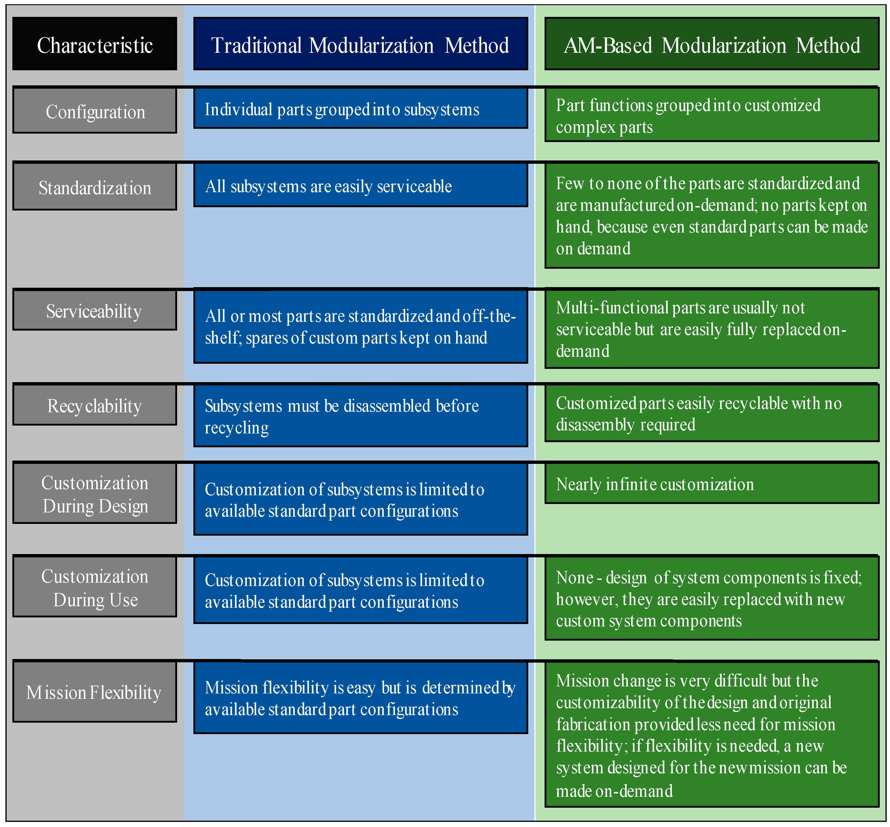
In light of this knowledge, the authors propose a definition of AM-based design modularization (
Figure 3 shows the definition graphically, compared to the traditional method):
AM-based product modularization is the process of decomposing a complex system into several complex multi-function components that can be optimized for a particular mission. This design methodology has five major characteristics:
- ▪
Few to none of the parts are standardized;
- ▪
No parts are kept in stock and all parts are made on-demand and optimized for the system and mission at hand;
- ▪
The multi-functional parts are rarely to never serviceable, but are easily replaced on demand and easily recycled;
- ▪
The multi-functional parts are not customizable in use, but they are easily customizable during design and fabrication;
- ▪
The system has only one core mission per configuration, but the lower cost and power of customizability during design and fabrication allows users to obtain more than one system to serve their needs.
3. Materials and Methods II: Rocket Design
In order to demonstrate the AM-based modular design process, a case study was developed; the topic of the study was the modularization of small solid-propellant rocket airframes. An excellent model to reference is the US Navy AIM-9X Sidewinder missile [
28], a rough sketch of which is shown in
Figure 4. The missile is steered to its target with the aid of a jet vane, so all the control surfaces are fixed [
29], a configuration that lends itself well to the use of AM to fabricate the airframe.
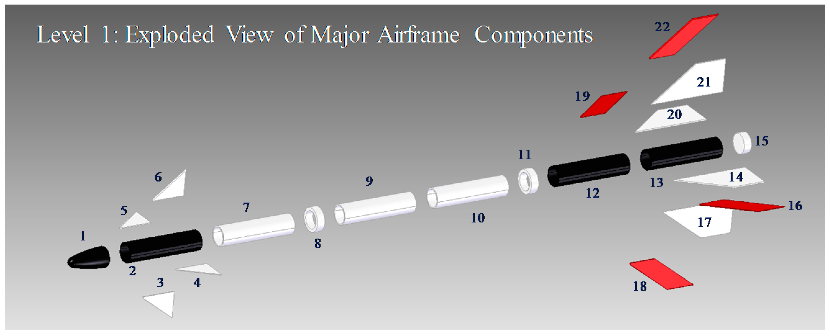
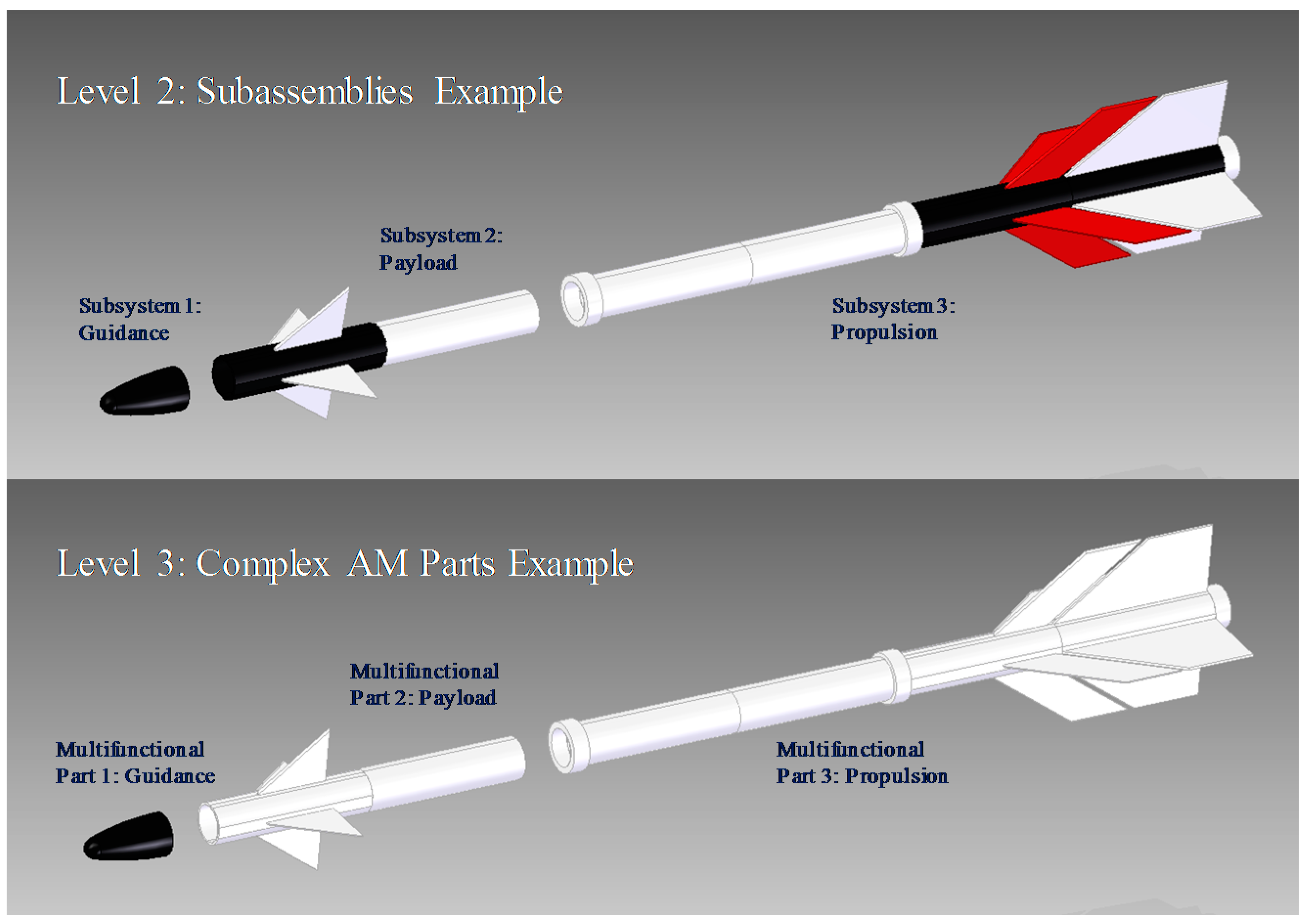
Figure 5 shows an exploded view of the Sidewinder missile; clearly, there are many ways that this type of airframe could be optimized into subsystems or complex parts. Level 1 shows the major airframe pieces, while Level 2 shows potential subassemblies that could be created. Level 3 shows the final stage of the AM-based design modularization. Three parts remain; the nose cone (guidance), the upper section (payload/warhead), and the lower section (propulsion). Many other configurations are possible; what is shown here is a very simple example to demonstrate the concept.
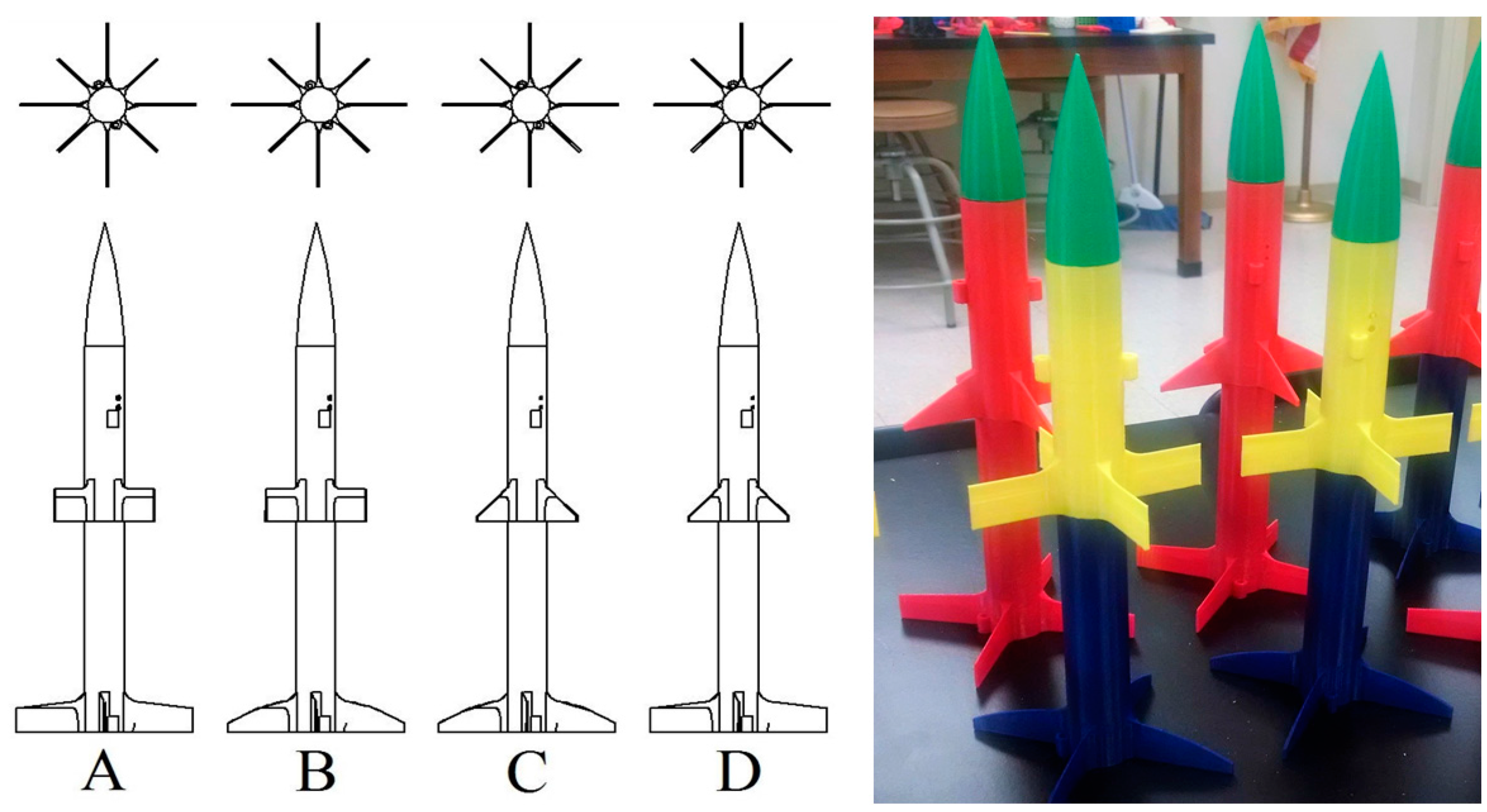
In order to examine this design approach further and provide a detailed example of rocket design, a series of new rocket designs must be generated. A configuration similar to that of the AIM-9 missile, with four wings at the bow section of the aircraft and four at the stern, was chosen; the front and rear wings were off-set from each other at 45-degree angles. The length of the new airframes was specified as 40 cm. The design variable between the two was decided to be the shape of the wings, as shown in
Figure 6; the shapes chosen were the delta, the clipped delta, elliptical, and rectangular. In order to best assess the effect of the fin shapes on the airframe performance, they were allocated according to a 2-level full-factorial design (
Table 1).
The choice of fins to analyze was purely a design decision, as many different combinations are possible beyond the four chosen. The purpose of this study was to explore the design modularization method, so several designs were generated purely to explore the effectiveness of the method. Future studies should be done to more rigorously analyze the effects of the various fin combinations, as very little literature exists on the topic and most previous work was done long ago and without the aid of sophisticated design and analysis tools.
While this design experiment is quite simple, it demonstrates the concept and approach in a clear and effective way, paving the way for more complex studies in the future.
Figure 7 shows the set of final designs, created according to the experimental design. Similar to the AIM-9 missile case previously discussed, the airframes were designed to be made in three pieces: the booster section, the payload section, and the nose cone, each printed as a single piece. As these rockets will be launched, it was necessary to include a set of launch rail lugs, clearly seen in
Figure 7.
The rockets were manufactured from polylactic acid (PLA), which is biodegradable, in case any of the specimens or parts were lost during launches; it is slightly heavier than standard ABS (acrylonitrile butadiene styrene) plastic but more environmentally responsible. The rockets were printed with the fused deposition modeling method, using 0.8 mm walls and 3% infill, for a total empty weight of around 80 g for a 40 cm airframe. The internal engine cavity in the booster section was designed to accommodate Estes C11-3 model rocket engines during launches.
4. Materials and Methods III: Fluid Dynamics Analysis
Now that the designs have been established, performance analysis on the rocket designs can begin. In order to guide expectations from the launch experiments and aid in interpreting the results, some preliminary performance knowledge is vital. To estimate these performance characteristics, a digital wind tunnel model was constructed using the ANSYS CFX® computational fluid dynamics (CFD) package (ANSYS Inc., Cecil Township, PA, USA).
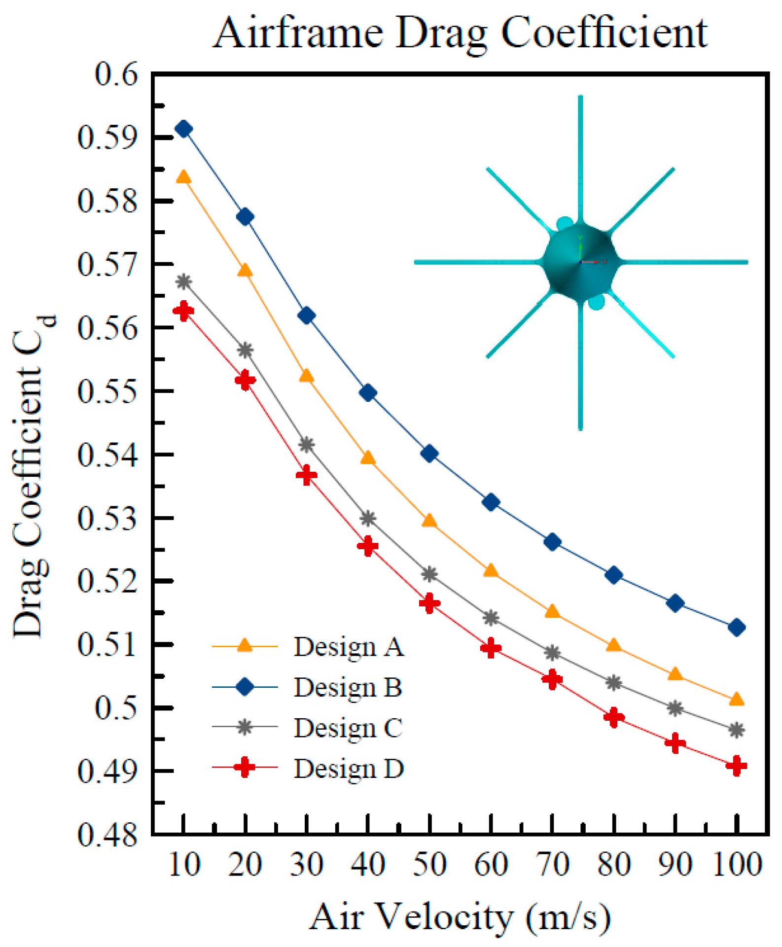
First, the drag coefficients for each of the designs were calculated in order to provide input for a preliminary analytical performance analysis. For each of the designs, the drag coefficient was found at various speeds, from 10 to 100 m/s, and plotted in
Figure 8. The fluid tested was air at one atmosphere of pressure, 28 degrees Celsius, and with a medium turbulence factor of 0.05. The cross-sectional areas for each rocket design were identical; the differences in drag were due to the various geometry combinations of fins.
The basic CFD model was built and analyzed in five major steps:
The geometry of each rocket was created using commercial 3-D modeling software (Siemens SolidEdge® ST9®, Siemens AG, Munich, Germany) and imported into the ANSYS geometry environment. Within this environment, a fluid domain was modeled around the rocket; the domain was square in cross-section and provided approximately 0.5 m of fluid distance from each surface of the rocket.
Upon geometry and fluid domain definition, the model was meshed using the ANSYS mesh environment. The mesh was set to fine for the entire domain, generating around 1.8 million elements per rocket, 380,000 of which were in the domain very near the interface between the rocket and fluid.
The meshed model was then imported into ANSYS CFD Pre®, in which the analysis characteristics are set. The center of mass and center of pressure for the rocket were found automatically by the software. The airspeed was set, as well as the ANSYS CFX® properties within this domain. Convergence tolerance was specified to be 1 × 10⁻⁵ with no limit on the allowed number of model iterations.
The model was then analyzed in ANSYS CFX® to find the drag coefficients on the rocket bodies. The drag was measured by tracking the force on the rocket body, in the direction of fluid flow, until steady state was reached. The average number of iterations to convergence of 1 × 10⁻⁵ was about 650, requiring around 25 min to run for each case.
Finally, the model was analyzed in ANSYS CFD Post®.
Within the ANSYS CFD Post
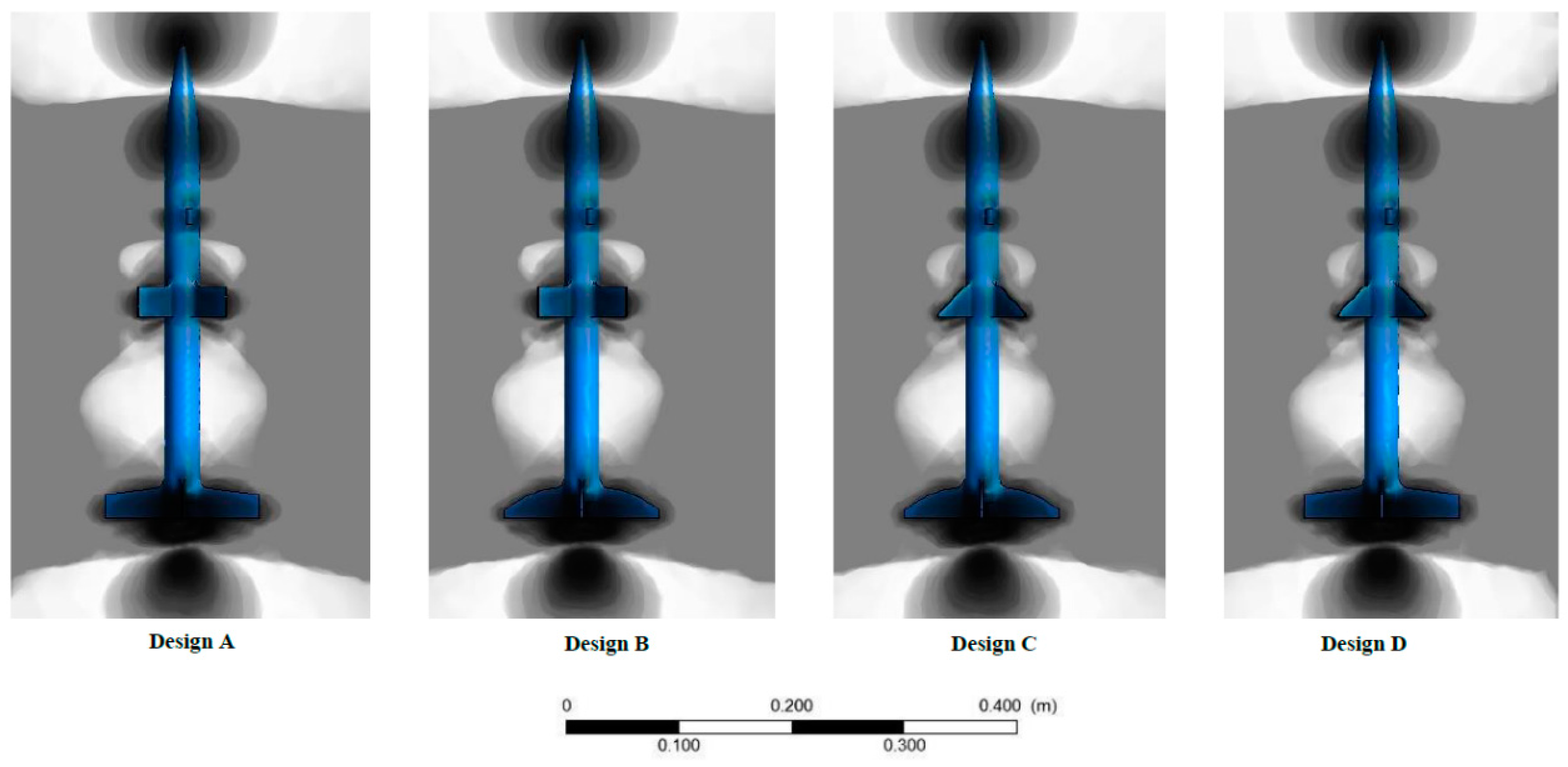
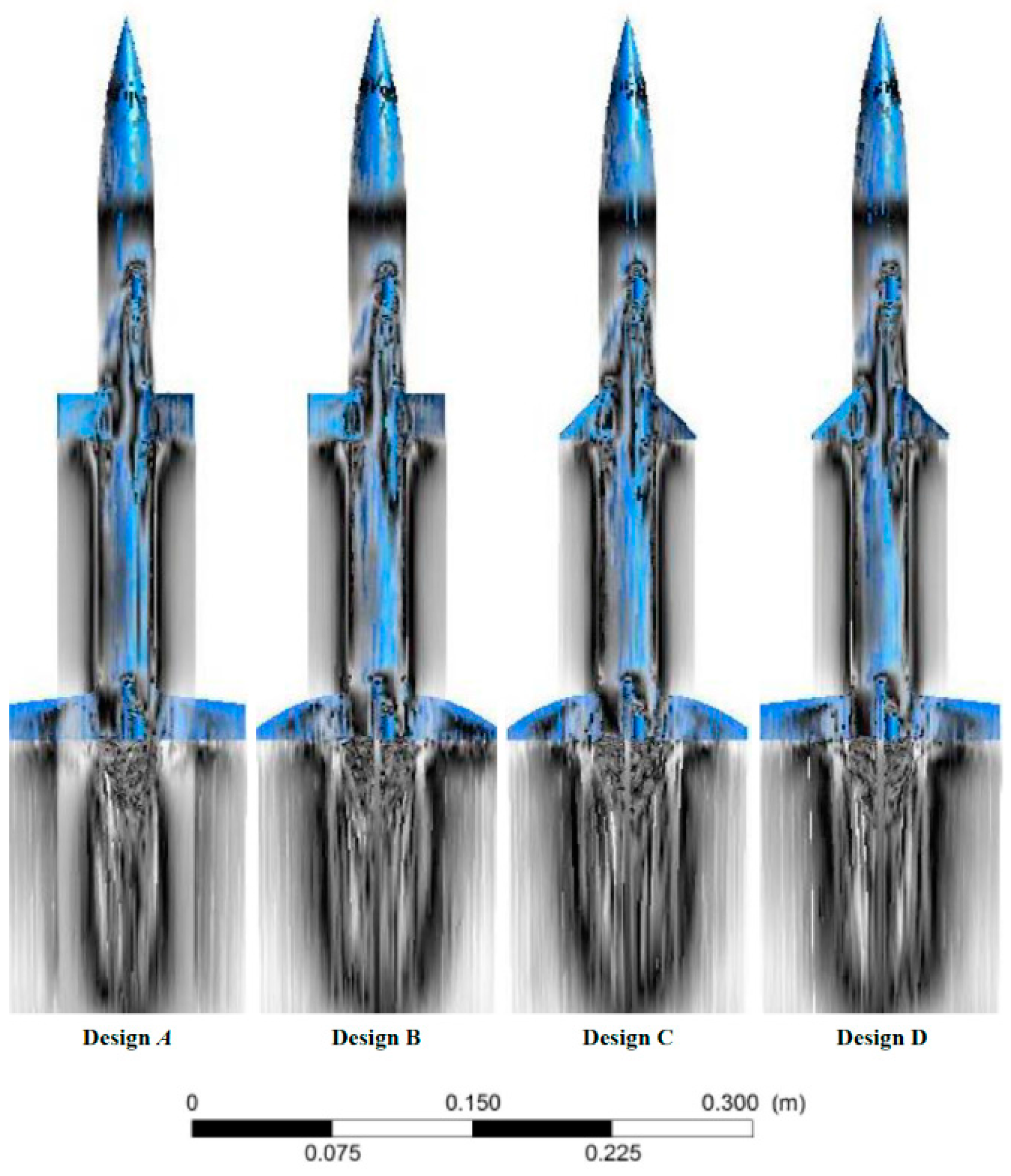
®, two other pieces of information were gathered. In order to be able to make some predictions about the stability and performance of the airframes before launch, a contour map of the pressure gradient after model convergence was collected, as well as the streamlines of the air flowing over the airframes. The results are shown in
Figure 9 and
Figure 10. In the cases shown, the traveling speed was 50 m/s. It was assumed that the angle of attack was constant during the CFD analysis, with no major deviation from perfectly vertical flight.
There are noticeable differences between the pressure gradients in
Figure 9, particularly between the upper fin shapes. The formation of the pressure wave ahead of the fins indicates that the rectangular fins will produce more drag, which was also found in
Figure 8 above. The results do not indicate any severe imbalances that will cause major instability during the flight. However, the streamline plots (
Figure 10) tell a different story. The flow pattern over Design A indicates that there may be significant disturbance in the flow during launch. It is anticipated that Design A will be the most unstable of the four designs during flight. The others appear to be stable, with Design D providing the most straight and stable flow pattern.
To better understand the results from this section, a brief extra literature review was done to find similar results from the published literature. A similar CFD model to the one presented in the present study was completed by Grover Aerospace [
30], which used rockets with only four control surfaces and a much higher velocity. The drag coefficients found are comparable to those found in this chapter, after taking onto consideration the differences in velocity; they are, on average, around 0.1 lower than the ones found here, but this is easily explained by the differences in velocity and a few control surfaces. In a second interesting study that was performed, Niskanen [
31] found that drag coefficient varied from 0.30 to 0.40 in simulation and from 0.25 to 0.40 in wind tunnel tests, both with subsonic flight speed. The rocket design studied had three control surfaces and flew at a significantly faster speed than the rockets used in the present study. Accounting for these characteristics, the results were comparable to those found in this paper and in [
30].
5. Materials and Methods IV: Analytical Calculations
As the drag coefficients were calculated in the previous section, an analytical dynamic analysis can be performed on the rockets in order to predict the flight altitude (apogee). The flight analysis is subjected to the following assumptions:
The air is static (no significant wind);
The properties of the air remain constant throughout the flight;
At the end of a time delay following burnout, the rocket motor will stop free-flight motion by ejecting the payload, in this case an instrument package and recovery system.
The engine characteristics from the manufacturer are shown in
Table 2. The manufacturer stated that the delay time between burnout and payload ejection is subjected to a tolerance of 10%. The exact velocity profile of the rocket during flight is not known, so minimum and maximum apogees will be calculated based on the minimum and maximum drag coefficients calculated in the previous section. It will be assumed that all of the original propellant will be burned off during the powered launch time, and therefore the mass will change with time. Launch site characteristics are shown in
Table 3.
The flight calculations [
33,
34,
35] for a dynamic flight path provide the total flight altitude that should be expected from launch. The flight is divided into four regions (
Figure 11): (1) pre-flight, when the motor is providing thrust to accelerate the rocket, but no motion has occurred yet; (2) powered flight, when the motor is providing thrust to the airframe; (3) free flight, where the rocket continues to coast until the payload ejection time; and (4) recovery, where the recovery system has been deployed and the rocket falls until it reaches the ground.
Figure 12 shows the free body diagram for a rocket launch. The thrust force propels the vehicle forward, while weight and drag forces oppose it. In this study, the airframes weighed approximately 80 g, the motor weighed 32 g at lift off and 21 g at burnout, the recovery system (a plastic streamer) weighed approximately 10 g, and the instruments weighted approximately 10 g, for a total of about 132 g (1.2945 N) at launch and 121 g (1.1866 N) at burnout. The thrust-to-weight ratio therefore is 17.0722, where 13.2563 is the minimum allowable for the motor (see
Table 2). The drag coefficient was found in
Section 4; a summary of the extrema is shown in
Table 4.
As shown in
Figure 11, the flight time of the rocket until maximum altitude is the sum of the powered flight time and the free flight time. Equation (1) demonstrates the relationship.
The altitude reached at the end of powered flight is given by Equation (2), where the
is the rocket mass (kg),
is the drag factor (dimensionless),
is the motor thrust (N),
is the gravity coefficient (m/s
2), and
is the burnout velocity (m/s).
The altitude reached at the end of free flight is shown in Equation (3), where the
is the rocket mass (kg),
is the drag factor (dimensionless),
is the gravity coefficient (m/s
2), and
is the burnout velocity (m/s).
Burnout velocity is calculated using Equations (4) and (5), where the
is the rocket mass (kg),
is the drag factor (dimensionless),
is the motor thrust (N),
is the motor burn time (s), and
is the gravity coefficient (m/s
2).
where:
The burn time (distinct from the thrust time) is given by Equation (6). This is a function of the motor thrust
(N) and impulse
(N·s).
The manufacturer of the engine gives an impulse efficiency rating of 0.90. Considering this, Equation (6) becomes Equation (7).
Finally, the drag factor is given by Equation (8). Area
is the cross-sectional area of the airframe (m
2),
is the air density (kg/m
3), and
is the drag coefficient (see
Table 4).
Given the information in
Table 2,
Table 3 and
Table 4, the drag factors for the four designs were calculated and are shown in
Table 5. The values of air density and cross-sectional area are constant and the drag coefficient was varied.
Table 6 contains the results for this section.
6. Materials and Methods V: Experimental Launches
To test the effectiveness of the designs, to collect experimental data to compare to the analytical solution, a series of launches were performed on the various rocket designs. The technical specifications were discussed in depth in the previous sections.
Table 7 shows the results from the launches. All the designs performed well except Design A, which was predicted by the streamline analysis in
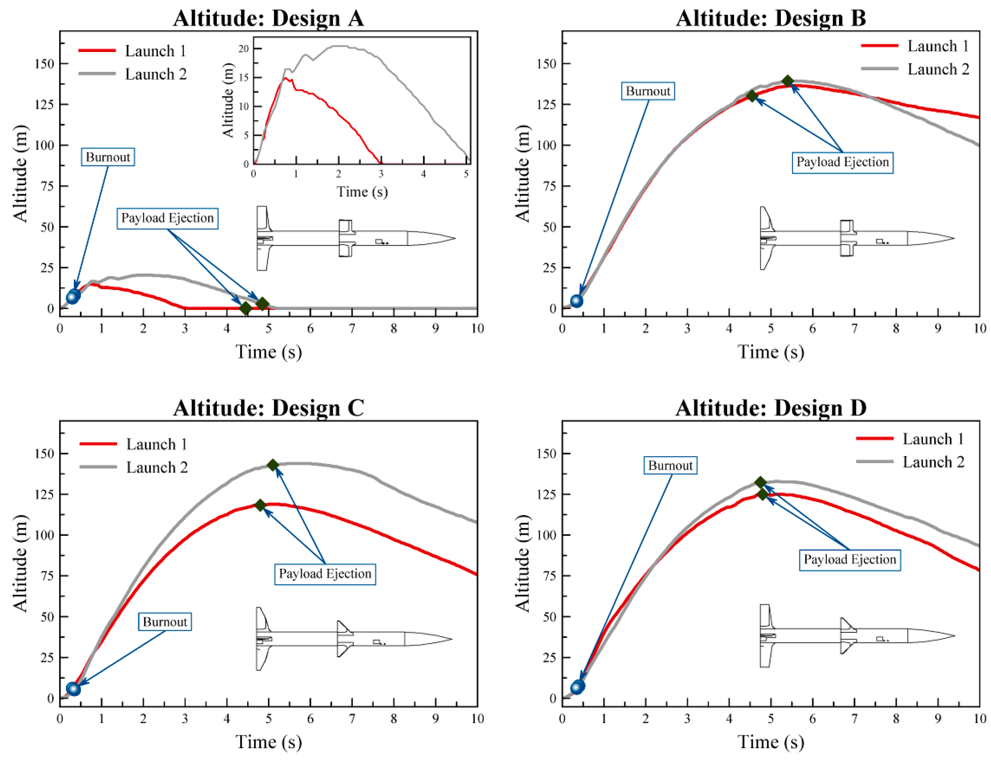
Section 4. Both launches of Design A (two separate aircraft) failed to reach any significant altitude and both were observed to tumble severely during the launches, crashing before the payload ejection in both cases. The instrument used was an AltimeterThree from Jolly Logic [
36], one of the best compact instrument packages available for rockets, drones, and other small aircraft.
7. Results
Figure 13 shows the altitude results for the experiment. The experiment was run twice in order to collect consistency data, as well as performance data.
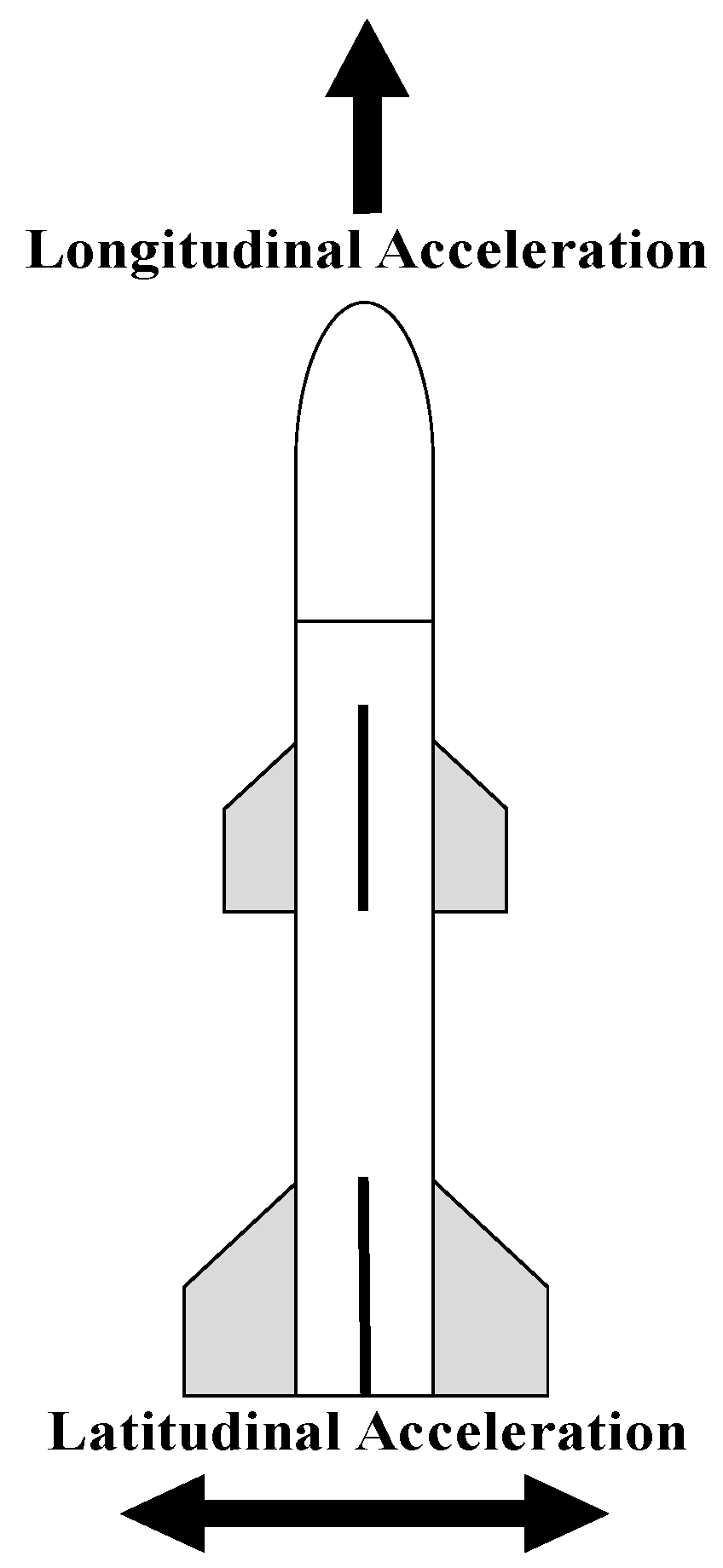
In addition to collecting the altitude data, the instrument package was able to capture the 3-D acceleration of the rocket as well. Both longitudinal and latitudinal acceleration were captured (
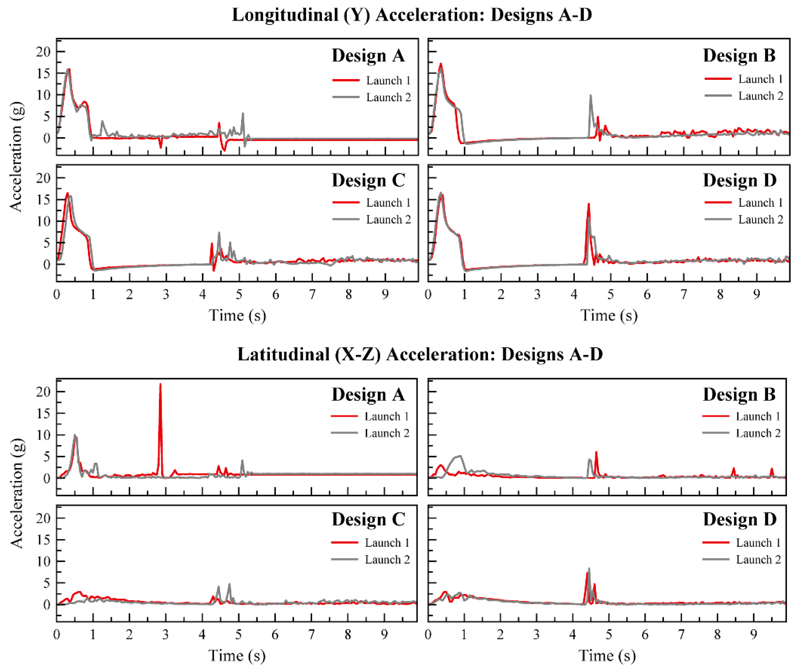
Figure 14). The longitudinal acceleration was the normal, expected launch acceleration. Latitudinal acceleration gives a good view of the stability of the aircraft during flight. The results are shown in
Figure 15; it is very clear from these plots that the different designs had noticeably different stabilities. The coefficient of gravity (g) is 9.79651 m/s
2.
8. Analysis and Discussion: Experimental Results
8.1. ANOVA and Model Adequacy
Figure 13 and
Figure 15 show the experimental results; the altitude data for each design are shown in
Figure 13 and the stability performance is shown in
Figure 15. It is clear in the plots that Design A failed on both launches, but the other six launches performed well. The design with the best altitude performance and consistency was Design B, while the most stable design during flight was Design D. The spikes in acceleration from approximately 0 to 1 s and from 4 to 5 s are due to the powered flight time and the payload ejection.
In order to explore the results more deeply and harvest additional conclusions, an analysis of variance (ANOVA) was performed on the experimental data to test the influence of the modular design on a variety of experimental responses, as shown in
Table 8.
The basic ANOVA assumptions were tested for each response; residuals must be plotted from a general linear model and satisfy the standard Fisher assumptions of normality, equal variances between replications, and run-order independence [
37]. Any datasets whose residuals do not follow a normal distribution must be transformed using a common statistical method known as the Box-Cox transformation [
38]. The raw data model was adequate for an ANOVA for five of the seven responses, while the two additional responses required a transform; the details are shown in
Table 8.
Model adequacy tests were performed using standard methods, with the normality tested using the Anderson-Darling Test [
39] and variances tested using the well-known Levine’s Test. The independence was checked by scatter-plotting the data in run order; none of the plots showed signs of patterning or data dependence. A standard test for the independence of data is the Chi-Squared test, but that could not be applied here because it requires integer data [
40]. The
p-values for the model adequacy test are shown in Columns 5 and 6 of
Table 9. The level of significance used was
, with a
p-value above that indicating adequacy.
The full ANOVA results are shown in
Table 9. A 2-way ANOVA was performed, so the main effects (upper and lower fin design) as well as their interactions can be explored. As stated above, the level of significance used was
. All data
p-values (Columns 2–4 in
Table 9) below 0.10 indicated that the factor of interaction had a significant influence on the response in question. The conclusions were:
- ▪
Maximum and mean altitude was very significantly influenced by the fin combinations, as well as their interaction during flight;
- ▪
Neither of the sets of fins nor their interaction had an influence on maximum longitudinal acceleration and only had some influence on the mean of this acceleration after the Box-Cox transform;
- ▪
The lower fin design has a weak influence on the latitudinal acceleration, which was much more pronounced after the Box-Cox transform;
- ▪
The fin designs and their interaction had a weak but significant influence on the mean latitudinal acceleration;
- ▪
The fin designs, but not their interaction, had a weak but significant influence on the standard deviation of the latitudinal acceleration.
In terms of flight performance, the formal conclusions from the graphical and statistical analysis of the tested cases were that the combination of elliptical lower fins with rectangular upper fins produced the best and most consistent altitude performance, while combining clipped delta lower fins with delta uppers produced the most stable flight. The combination of clipped delta lower fins and rectangular upper fins produced a highly unstable and unreliable design.
8.2. Experimental Error Analysis
Clearly, there were discrepancies between the theoretical and experimental data.
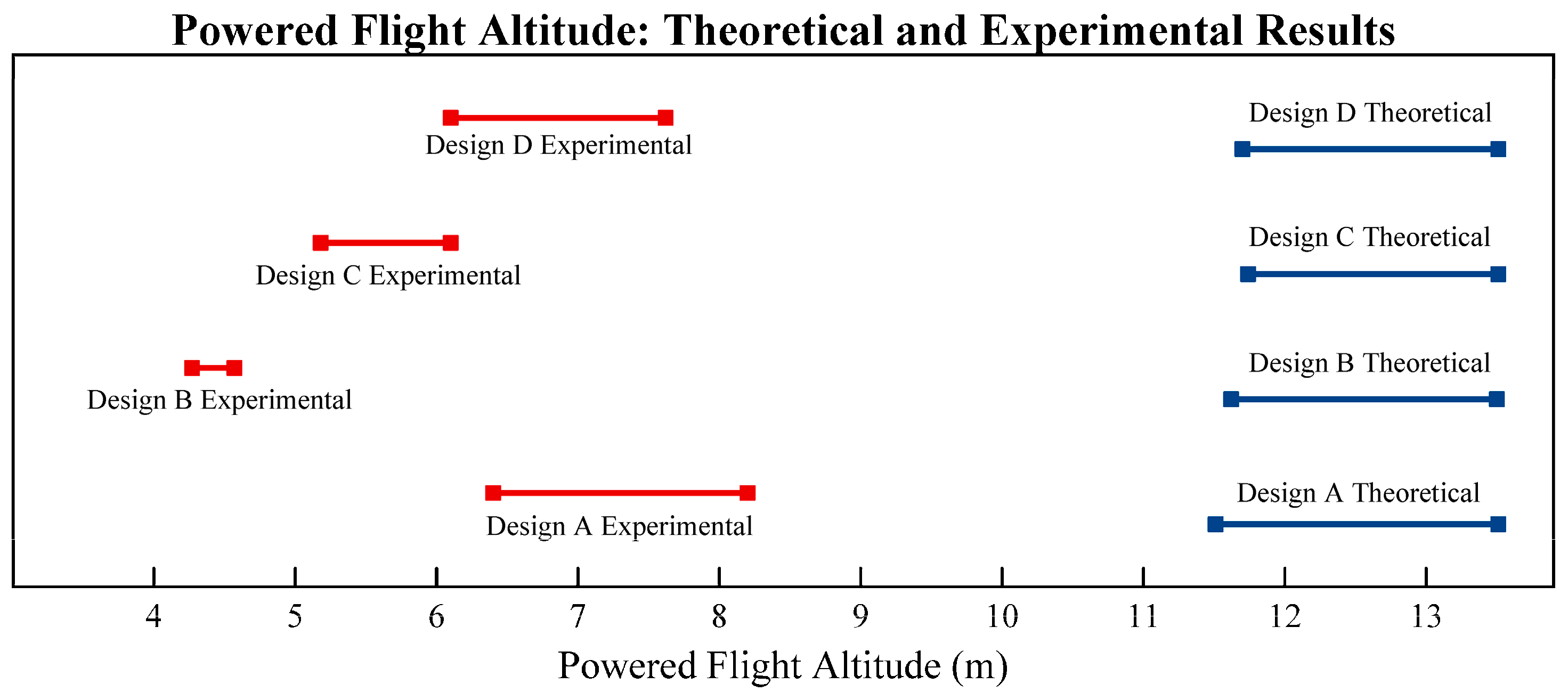
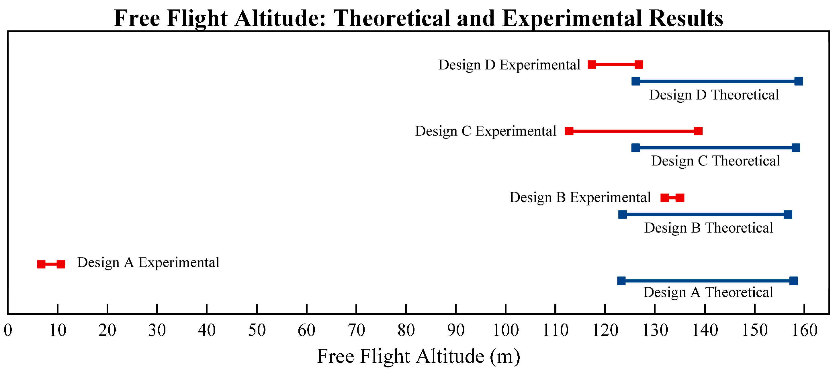
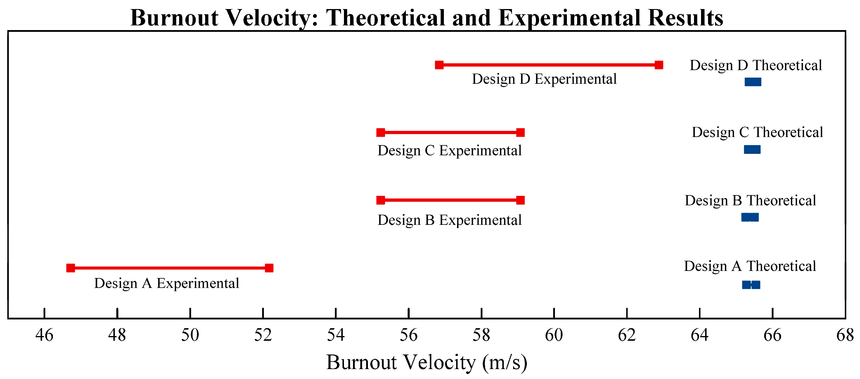
Figure 16,
Figure 17 and
Figure 18 show the one-on-one comparison of the theoretical and experimental results for the altitude and burnout velocity. The ranges for the theoretical results were those based on the minimum and maximum drag coefficients, while those for the experimental results were from the two experimental iterations. The discrepancies were thought to be introduced into the experiment via four modes: (1) rocket skin fluid friction from 3-D printing lines; (2) potential payload ejection before true apogee; (3) launch rail friction; and (4) angle of attack variations. Each of these possible sources of error were examined in detail. General random uncertainty within the experiment was considered to be trivial in magnitude compared with the obvious error sources and was therefore not considered in detail in this analysis.
Skin friction was tested using an ANSYS CFX® model, comparing the drag coefficients for the nose cone for smooth and realistically layered models. Payload ejection time was compared with the true apogee to determine if the ejection prematurely disrupted the flight. Launch rail friction was analyzed to determine if it significantly influenced the powered flight altitude.
8.3. Error Analysis: Skin Friction
Since the parts used in this experiment were 3-D printed, they have a slightly rougher surface finish than parts made using injection molding or other common plastic fabrication techniques. Logically, this could have some effect on the drag coefficient around the nose cones of the rockets, as the laminar boundary around the surface is thinnest at the beginning of the flow [
37]. However, in many cases, a rougher surface at the beginning of the flow may actually decrease the drag, as it forces the flow to become turbulent earlier [
41,
42]. While it is obvious that this caused some kind of effect, whether that effect is positive or negative was unknown, requiring a brief experiment to answer the question.
An ANSYS CFX
® simulation was built to test the influence of the surface roughness on the nose cone drag, comparing the drag coefficient between the smooth and a realistically rough surface (
Figure 19). The relative roughness for the geometry tested was about 1.97 × 10
−3. Only the nose cone was tested, as background research [
41,
42], and the flowline analysis (
Figure 10) indicated that most or all of the of the drag induced by surface roughness would occur on the cone. Computational expense was a factor in the decision as well and required several hours to perform the analysis to a tolerance of 1 × 10
−6 on the realistic cone alone.
The smooth cone model was created using a standard revolved axis protrusion, while the realistic cone was built as a series of 0.20 mm layer, with protruding ridges equal to the lateral uncertainty for the printer that was used to create the original parts. The flow was standard dry air at one atmosphere of pressure, flowing over the cone surface at a normal speed of 50 m/s. Both models were analyzed twice using different computers and fresh formulations for each; the results were identical for the two runs of each model, indicating that the setup was correct and consistent.
The analysis indicated strongly (
Table 10) that the realistic roughness on the skin actually provided an advantage by reducing the drag coefficient. This result was interesting, but not unexpected; such results are fairly common [
41,
42] for blunt-type geometries such as cones in a turbulent flow. The roughness likely caused the flow to trip earlier, providing thicker laminar boundary layer coverage on the surface in the flow. This deserves further study in future work.
8.4. Error Analysis: Payload Ejection
It was noted earlier in this paper that much of the discrepancy between the theoretical and experimental performance likely was due to payload ejection before true apogee was reached. Upon further study of the raw data, this phenomenon is obvious;
Table 11 clearly shows that the payload ejection was indeed a significant limiting factor on the total altitude of the rockets and most likely explains the different between the theoretical and experimental altitude values, except for the failed Design A. In the six successful launches, the aircraft continued for a significant amount of time after ejection (see
Table 11 and
Figure 13), indicating that the rockets maintained significant momentum before ejection. This limiting factor should be considered strongly in future experiments; a motor with a much longer delay or no ejection should be utilized.
8.5. Error Analysis: Launch Rail Friction
The friction between the rockets and the launch rail was the most likely culprit for the high error found in the powered flight time performance (
Figure 16), as the error for the free flight (
Figure 17) is much lower or not present. It could also explain the lower-than-expected burnout velocity (
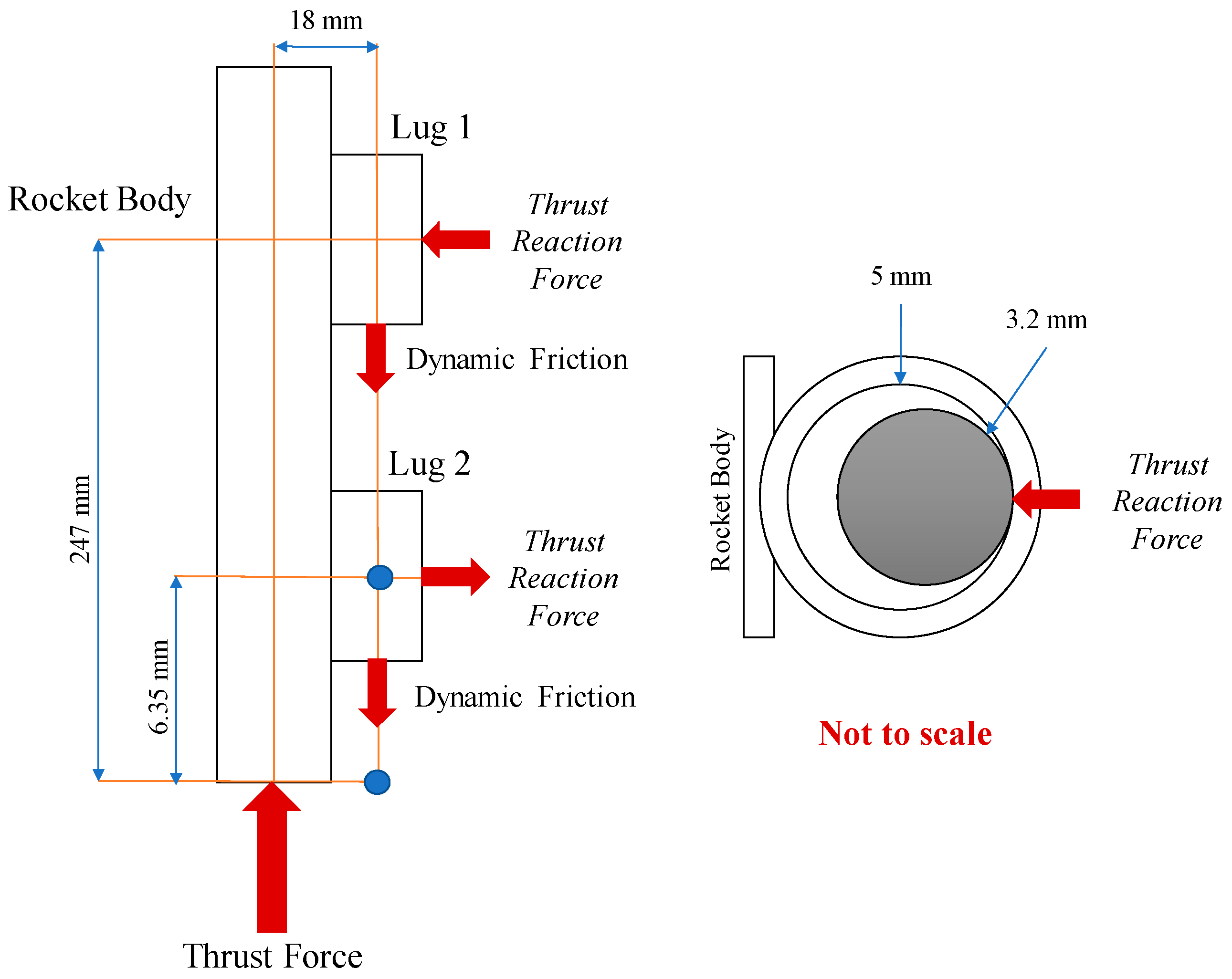
Figure 18). To test the influence of this friction source, a simple analytical model was constructed to calculate the potential friction factor. The free body diagram is shown in
Figure 20. It was assumed that the dynamic friction coefficient
[
43] for a plastic-steel interface.
The launch mass of each rocket was 132 g (1.295 N), and the engines used produced a thrust of 22.1 N. Using basic static moment analysis (
Figure 20), the upper thrust reaction (
) was found to be 1.653 N and the lower (
was 1.652 N, for a total of 3.305 N. Thus, the dynamic friction force was:
While this is not a large force, it is certainly significant in the problem at hand; it adds 12.7% to the apparent weight of the aircraft at launch for a total weight of 1.4595 N (148.8 g); this is nearly the weight of the recovery system and instrument package combined. The new thrust-to-weight ratio is 15.142, not far from the minimum allowable ratio of 13.256. This additional friction force certainly contributed to the error found in this experiment, particularly the errors shown in
Figure 16.
8.6. Error Analysis: Angle of Attack Variation
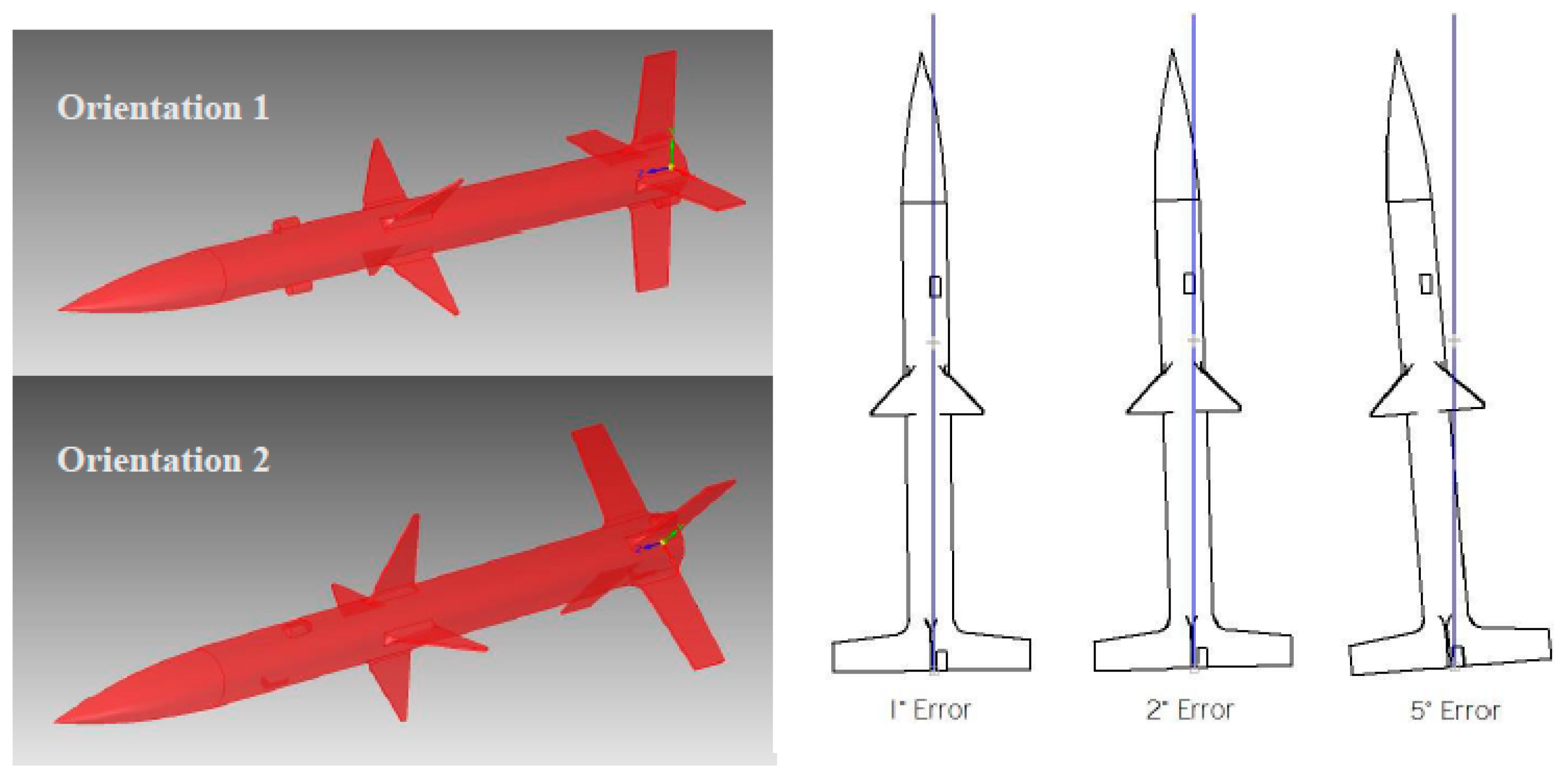
One of the basic assumptions made during the CFD and analytical analyses was that the angle of attack was constant during flight. If this assumption is invalid, the wetted area of the airframe changes, increasing the drag area. Since the rockets used in this study had a total of eight control surfaces at two locations, the roll rotation angle is also influential in this. In order to analyze the potential effects this may have, a brief sensitivity analysis was performed. Design D, the most stable of the four designs, was analyzed in ANSYS CFX
® in the same way as in Chapter 4 but with the angle of attack offset. Three offsets were used: 1°, 2°, and 5°. These are reasonable points of observation, as the observed rocket behavior during flight (on the six successful flights) did not show significant deviation from the constant flight angle. In order to test the effect of roll angle, two orientations were used; one with the upper control surfaces set at 90° and the other with the lower control surfaces set the same way. Two different air velocities were used, 50 and 100 m/s. The model setup is shown in
Figure 21, and the results of this study are shown in
Figure 22.
As seen in
Figure 22, the impact of varying the angle of attack had a trivial impact on the measured drag force on the body. While all of the orientations were subjected to a higher drag force than the original run (from Chapter 4), the largest variation at 50 m/s was around 3.46% (an increase of 0.03 N), while it was 3.81% (increase of 0.14 N) at 100 m/s. While not an overwhelming factor in this study, it does add to the apparent vehicle mass; the results imply that this would be a major consideration at higher velocities. The orientation of the rocket did not appear to have a noticeable impact on the results, as no patterns or trends appeared in the data.
9. Analysis and Discussion: Manufacturing Implications of Error Analysis
The error analysis discussed in
Section 8 provides some guidance for the production of the next generation of small modular rockets in order to avoid the pitfalls encountered in the current study.
The skin friction study shows the influence of the surface roughness of the parts, which is controlled primarily by varying the layer thickness and the build speed. Designers should consider their choice of process settings on the skin friction, eventually finding the optimal design settings to balance easier manufacturing with increased performance.
Payload ejection time can be controlled mainly by the choice of engines for the flights. 3-D printing produces custom geometry, so accommodating a variety of engines is a simple matter. The information collected in this study could aide in the proper selection of engines for the types of rocket in this study.
Clearly, the launch rail friction had an impact on the results of this experiment. A better launch method should be used for these types of rockets, including tray or tube launching, in future launches.
The influence of the angle of attack variations increases with velocity, so designers should make sure that the airframes are as symmetric and well balanced as possible. They should also be checked for printing errors before launching to ensure that no unbalance exists in the geometry.
10. Analysis and Discussion: Design Modularization
The main purpose of this study was to develop, design, and test an airframe design based on feature modularization into complex parts, instead of part modularization into subassemblies. The rocket airframes used in this study were built in three parts; the booster, the payload, and the nose cone. In a real aircraft, such as a sounding rocket or missile, the booster section would contain all the propulsion components, the payload section would contain the warhead or instruments, and the nose cone would carry the guidance system and computer. Based on the need of the mission and the sizes of the AM equipment available, the number and scope of the complex parts can be adjusted.
The rockets used in this study were deliberately manufactured out of polylactic acid (PLA) because it biodegradable and fully recyclable; if any rockets were lost, the pollution to the environment would be minimal. Rockets made from the standard ABS would be significantly lighter but are not at all environmentally-friendly or as easily recyclable.
The modularization technique dramatically reduced the effort in creating the designed experiment used in this study. Two different booster and two different payload designs were made, then combined into four separate unique rocket designs that had significantly different performances. If the experimental design had not called for measurable and predictable combinations of the factors, there is virtually no limit to the unique designs that could be made. Production time was very brief as well, requiring around 10 h to design, verify, set up, print, and assemble the rockets. While most commercial model rocket producers would likely be able to produce rockets much faster, this depends on months or years of design, testing, and preparation to produce stock parts. The design modularization technique can produce a successful launch of a completely unique design 10 h after the original idea is proposed. The benefits of this technique to the manufacturing of airframes in general is obvious.
When compared to the cost of commercially available alternatives to the rockets used in this study, the modular designs were very cost efficient. Not including the labor of the authors, each of the rockets required about 100 g of material (including supports and waste) and about 8 h of electricity at 30 W, a total of about $2.25 per airframe. Even if the designer chose to use expensive proprietary filament instead of open source filament (as was used in this study), the cost would remain under $10.00 per airframe. The motors for each launch cost about $6.00, but this should not be considered, as any rocket would require the same launch cost.
Similar alternatives from the world of model rockets are shown in
Table 12 (source: Amazon.com, February 2017). Clearly, the modular 3-D printed rockets are far more cost effective. Most of these have airframes made from cardboard or very thin plastic, unlike the strong airframes used in this study. In all cases, the airframe weight is comparable due to the ability to 3-D print the airframe as a complex hollow structure.
While the method could obviously be used to produce cheap customized model rockets, the greatest benefit would be in the production of sounding rockets and military equipment. The model rockets provide an interesting and relatable case study for exploring this design method, but much further exploration and development of the method is needed before it would be trusted for more vital and complex applications. However, the benefits are clear and this further development is certainly warranted.
11. Conclusions
The present study explored a design modularization method that combines features into complex individual parts instead of parts into subassemblies. The results strongly suggest a number of general conclusions about the design modularization method and about the feasibility of the 3-D printing of rocket airframes, including:
- ▪
Design modularization via combination of features into complex parts is a feasible design methodology for rockets and other airframe-based products;
- ▪
3-D printing, particularly extrusion-based processes, is an excellent method for producing the complex multi-feature parts needed for optimized airframes;
- ▪
It is possible and feasible to produce airframes that have excellent recyclability and low environmental impact by utilizing biodegradable materials in the design;
- ▪
The airframe designs can be adjusted and customized nearly infinitely;
- ▪
The exact shape of the rocket fins and their combinations have a very significant influence on the performance and stability of the airframe;
- ▪
AM and modular design greatly simplify the measurement and adjustment of the fin influences on performance;
- ▪
While the performance of the rockets fell short of the analytical predictions, the sources of the errors were very simple to identify due to the simplified design;
- ▪
The print lines on 3-D printed parts seemed to provide an advantage, not a disadvantage, to the rockets as it reduced the drag coefficient of the nose cone;
- ▪
The payload ejection time was too short for the motors chosen, a factor that should be considered heavily in future studies;
- ▪
The launch rail introduced a significant amount of friction, causing the rockets to launch and burn out at slower speeds;
- ▪
Five of the seven experimental responses produced data whose residuals followed a normal distribution without any statistical transforms, suggesting that very little random error is contained in the experiment.
In conclusion, this study was unique and was very successful as a detailed case study in modular design; very little research has been done in this area, and this study should provide background and motivation for further work. The performance of the modular rockets was very easily analyzed, with the sources of error easily found and explained; the modularization greatly eased analysis of the errors, as there were far fewer parts to consider. Future studies using modular design methods with AM can easily correct these sources of error, as the complex parts have great design and geometry freedom and are not limited by commercial part standards. In a standard design, it may be difficult or impossible to correct sources of error found during experimentation if the design is dependent on a series of standard parts. Using part modularization, few or no standard parts are used, so infinite adjustment and correction can be performed on designs in nearly real-time.
