Dynamics Modeling of a Rigid–Flexible Coupled Flapping-Wing Robot and Diffeomorphism-Based Disturbance Rejection Attitude-Constrained Control

Abstract
1. Introduction
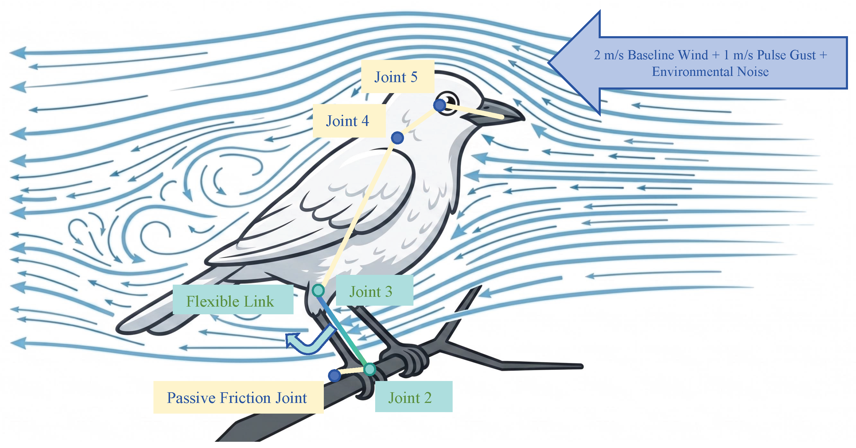
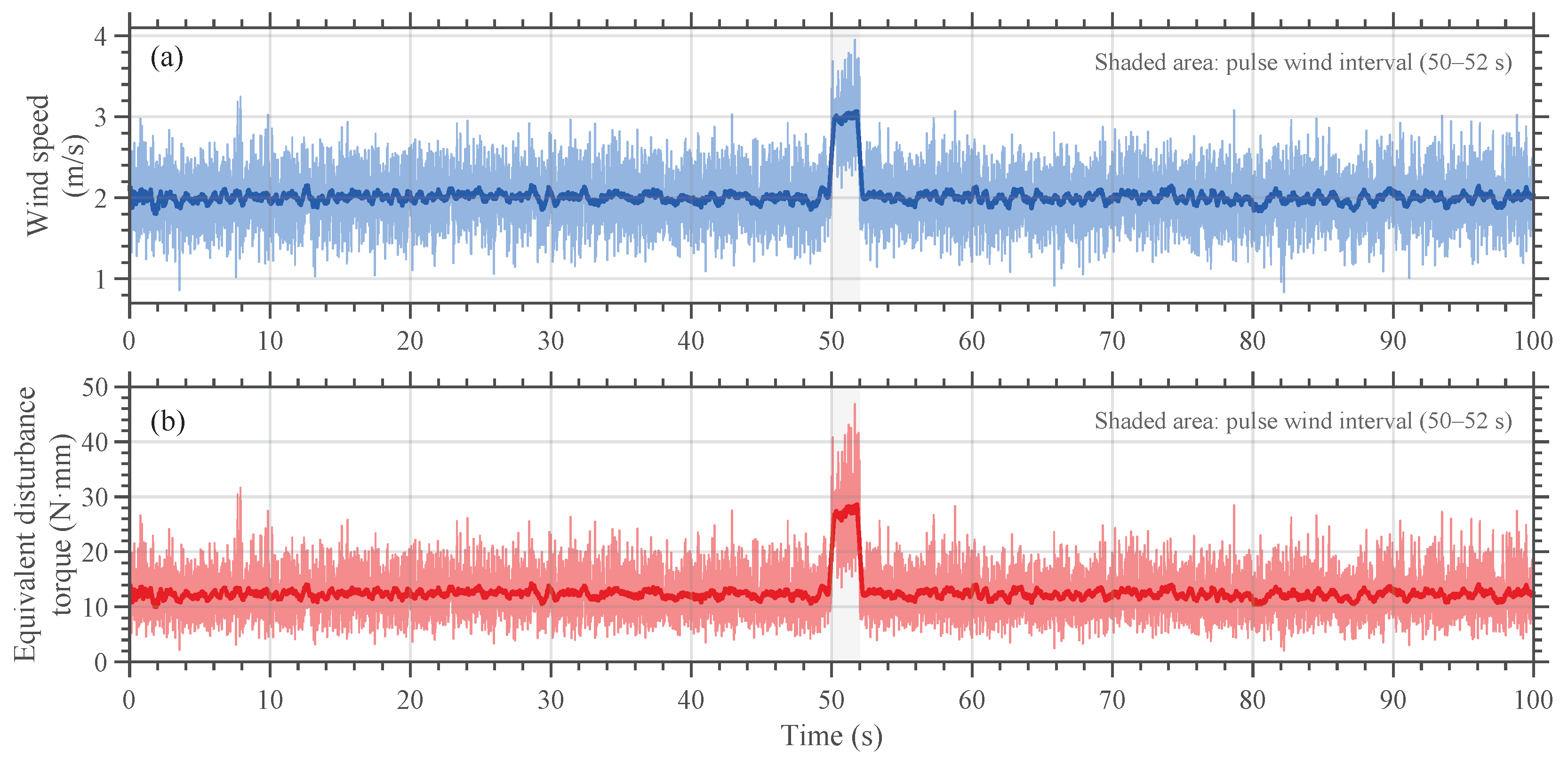
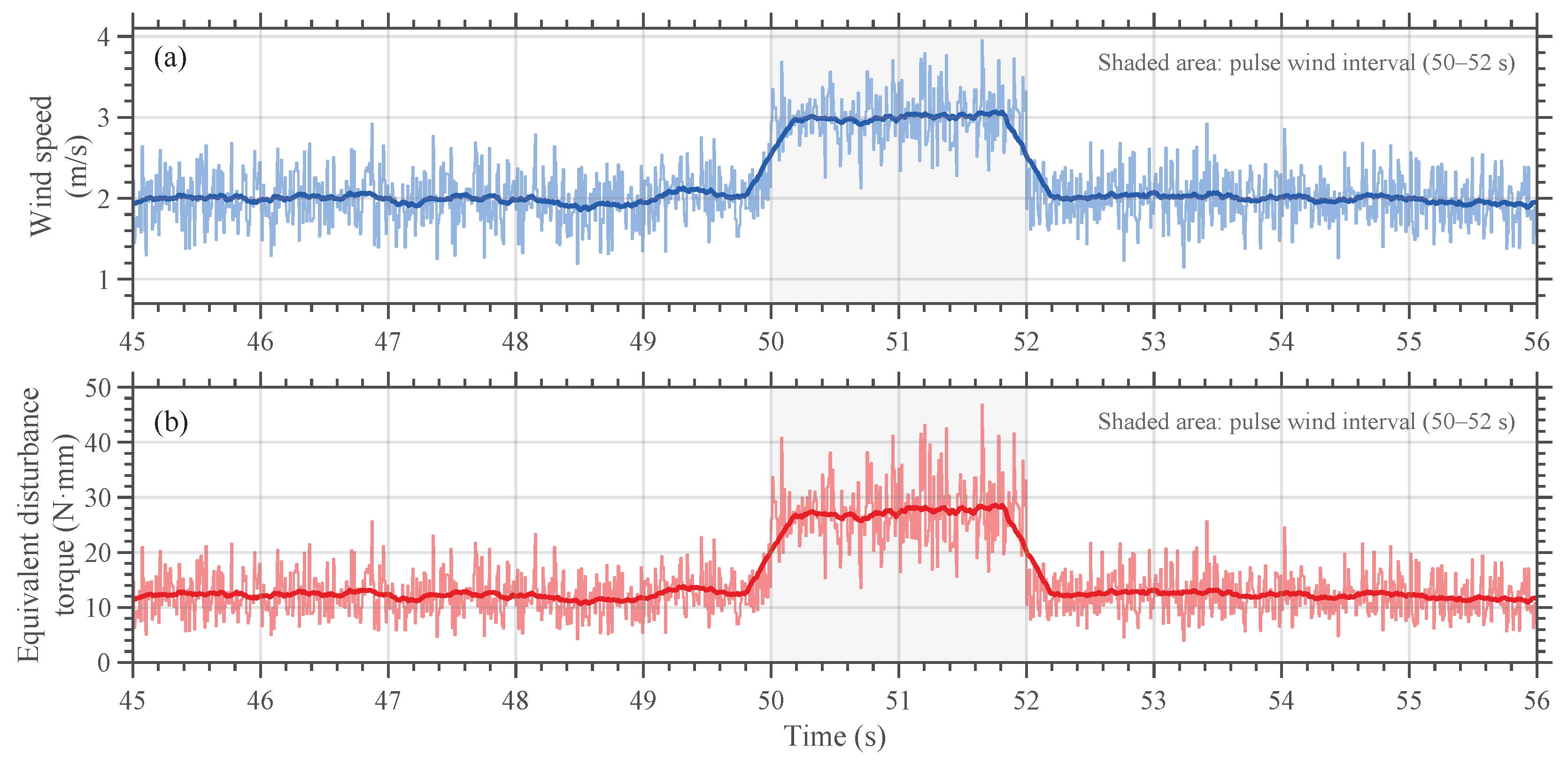
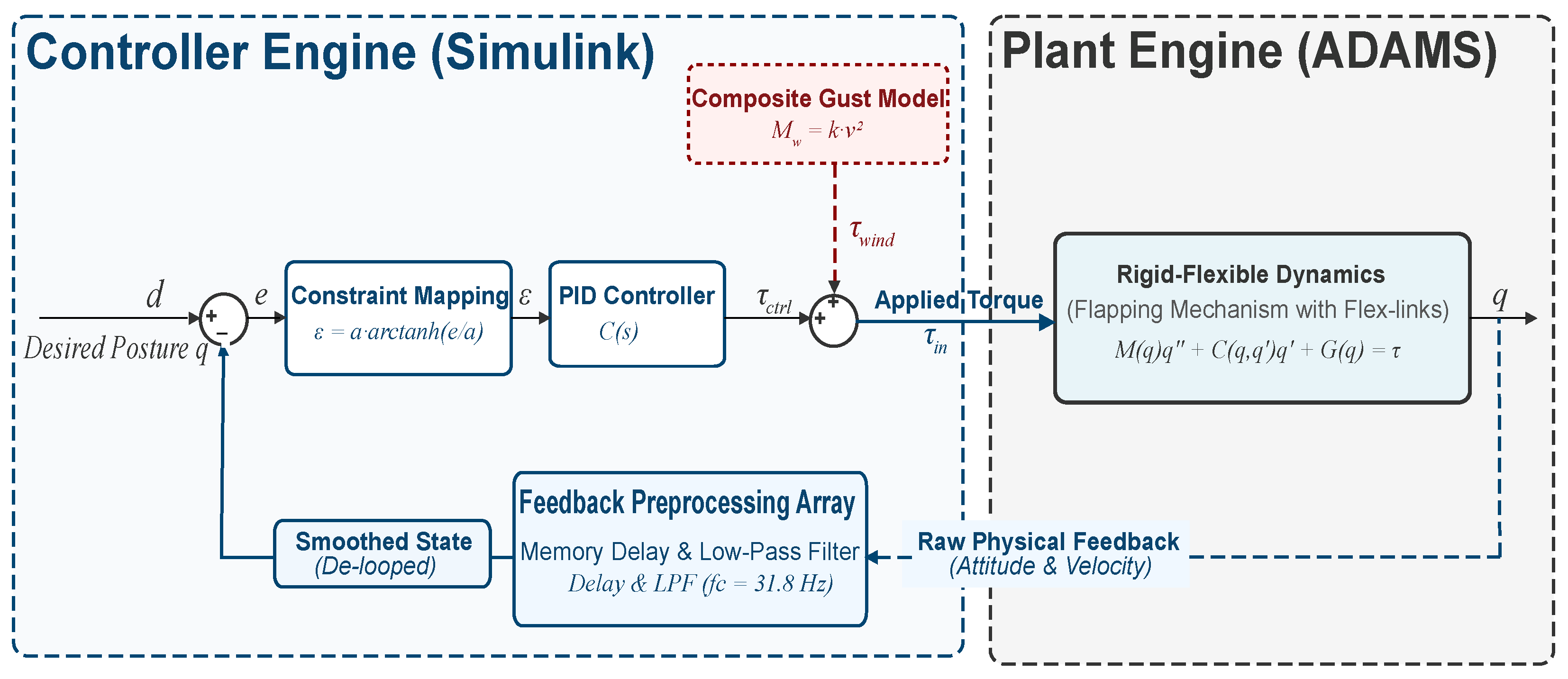
- C1. A cross-domain co-simulation platform incorporating flexible links and compound wind disturbances is established. By integrating ADAMS and Simulink, the proposed platform overcomes the limitations of single-software simulation and enables the coupled analysis of large-deformation flexible links and compound gust disturbances, including a 2 m/s baseline wind, a 1 m/s transient pulse disturbance, and white noise.
- C2. The nonlinear regulation mechanism of diffeomorphic mapping for attenuating measured-channel flexible excitation is investigated. The results verify that the proposed method can reduce the influence of high-frequency components in the measured feedback and torque-response channels and improve the dynamic stability of the system.
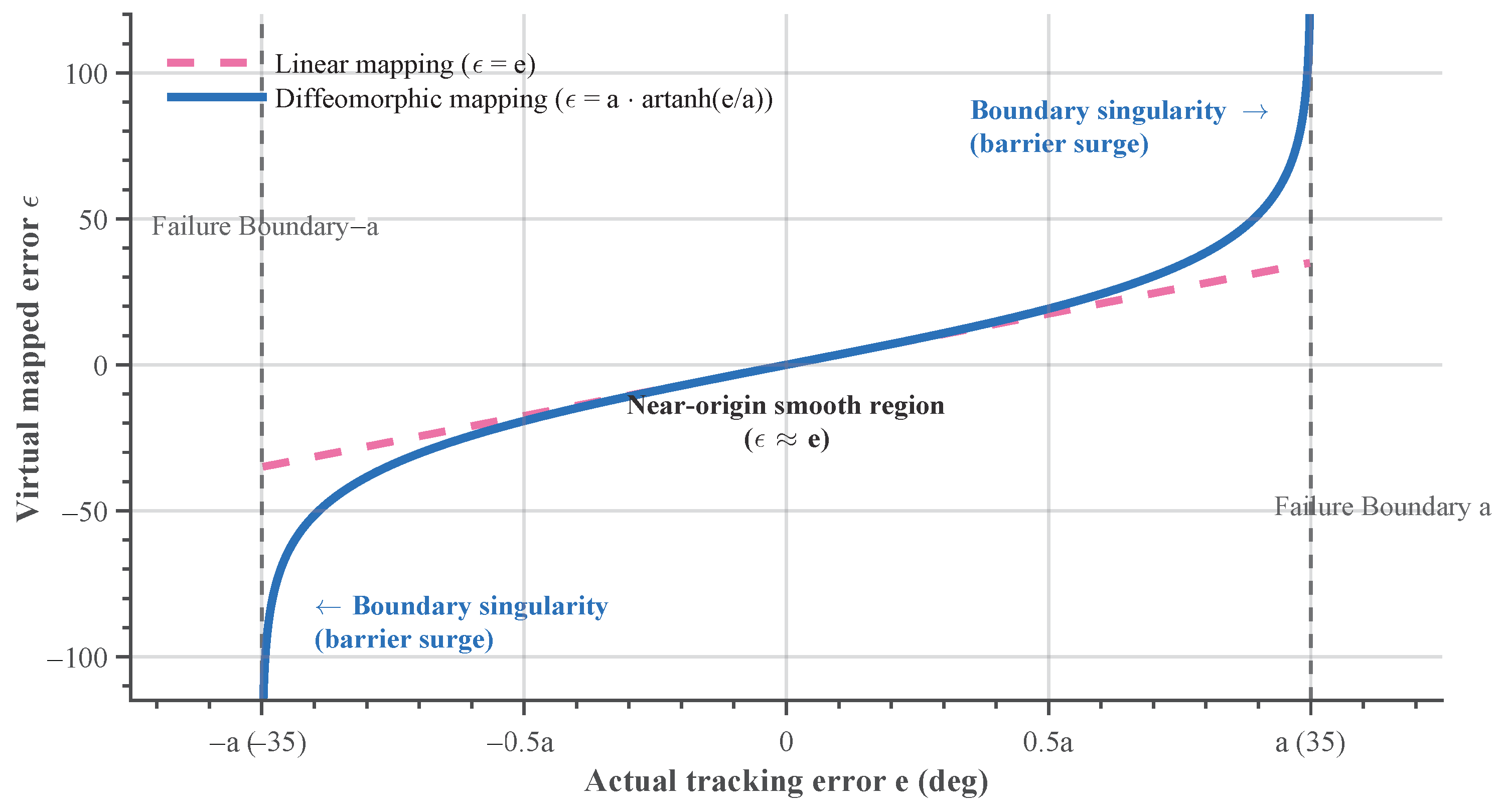
- C3. It is demonstrated that, under transient pulse wind disturbances, the diffeomorphism-based nonlinear control strategy can prevent boundary loss through boundary-aware error reshaping. After the disturbance disappears, the proposed method enables stable attitude recovery, thereby achieving robust stabilization and pose restoration in transient gust environments.
2. Materials and Methods
2.1. System Dynamics and Environmental Modeling
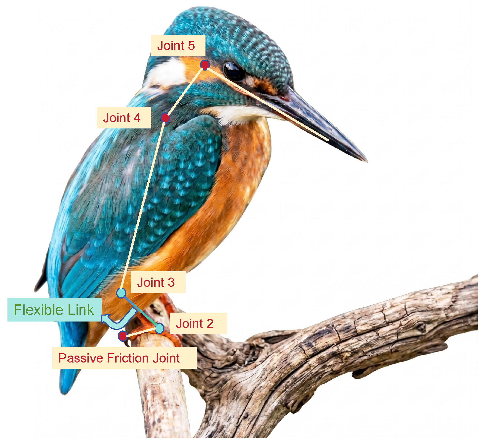
2.1.1. Baseline Rigid-Body Configuration and Nominal Trajectory Definition
2.1.2. Rigid–Flexible Coupled Dynamic Model of the Bio-Inspired Leg Link
2.1.3. Modeling of Transient Pulse Compound Crosswind Disturbances
2.2. Problem Formulation and Control Strategy
2.2.1. Static-Friction Failure Risk in Perching and Grasping
2.2.2. Physical Mechanism of the Diffeomorphism-Based “Nonlinear Air Wall” for Boundary-Aware Flexible-Excitation Attenuation
2.2.3. Controller Implementation and Co-Simulation Input Form
2.3. Nominal Convergence and Practical Boundedness Analysis
2.4. Construction of the ADAMS–Simulink Co-Simulation Platform
2.4.1. Closed-Loop Signal-Flow Topology Design Based on Diffeomorphic Mapping
2.4.2. Distributed Weighted Injection of Complex Wind Loads and Feedback Noise-Suppression Mechanism
3. Results
3.1. Trajectory Tracking and Suppression of the Flexible Whip-like Effect Under Ideal Wind-Free Conditions
- 1.
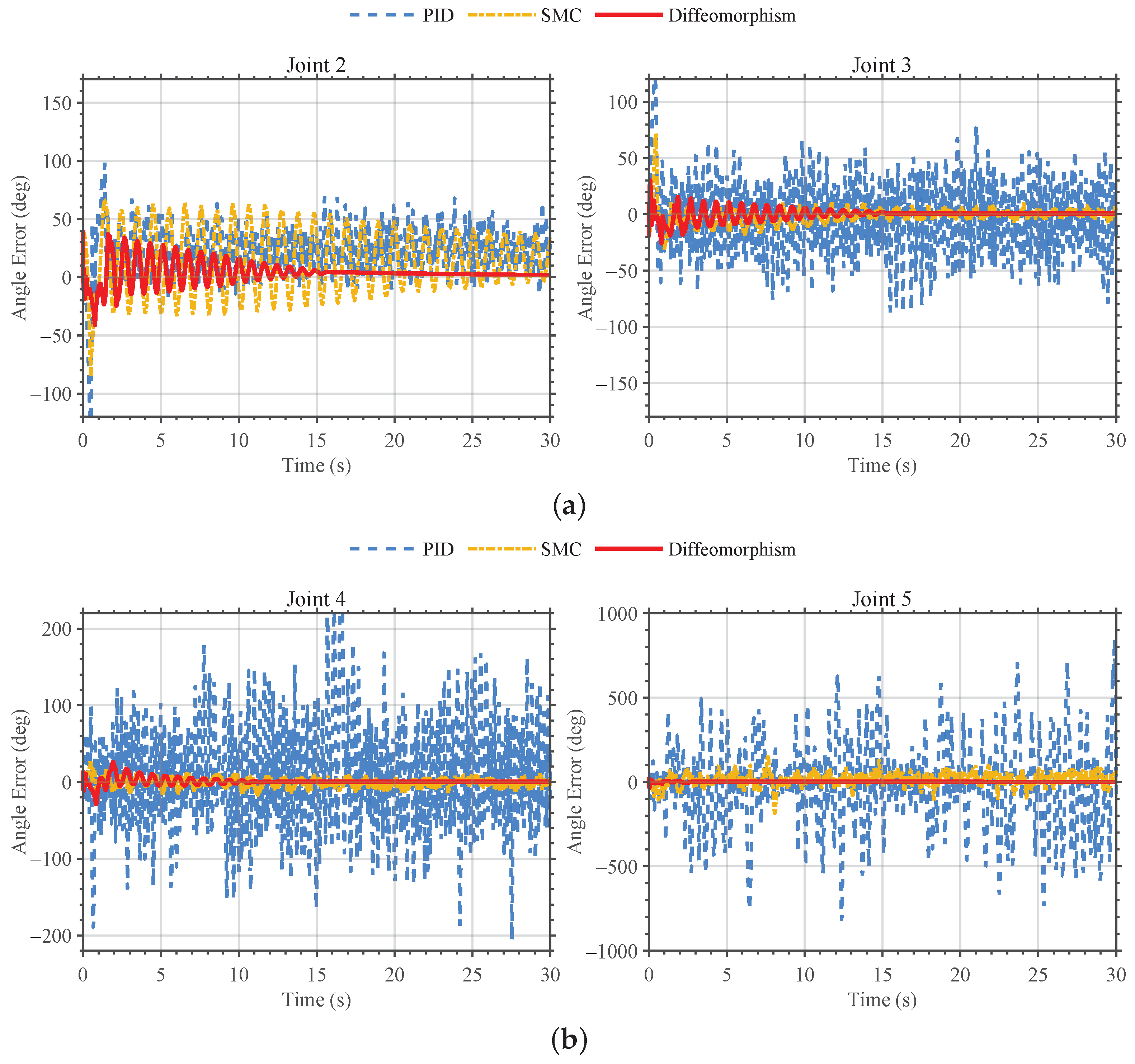
- PID and SMC do not converge, whereas the proposed controller achieves the lowest RMSE (), lowest maximum deviation (), and convergence within about 30 s.
- 2.
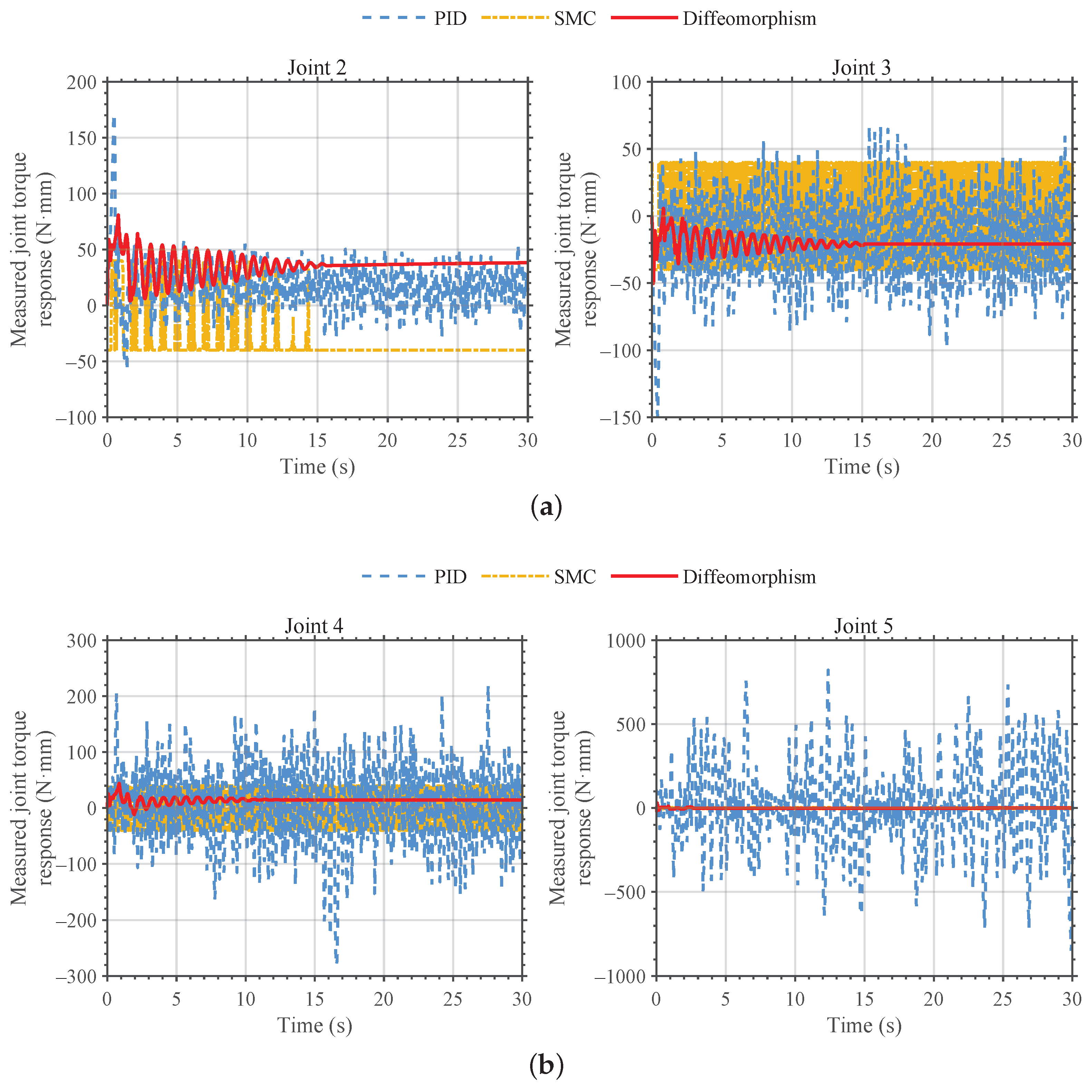
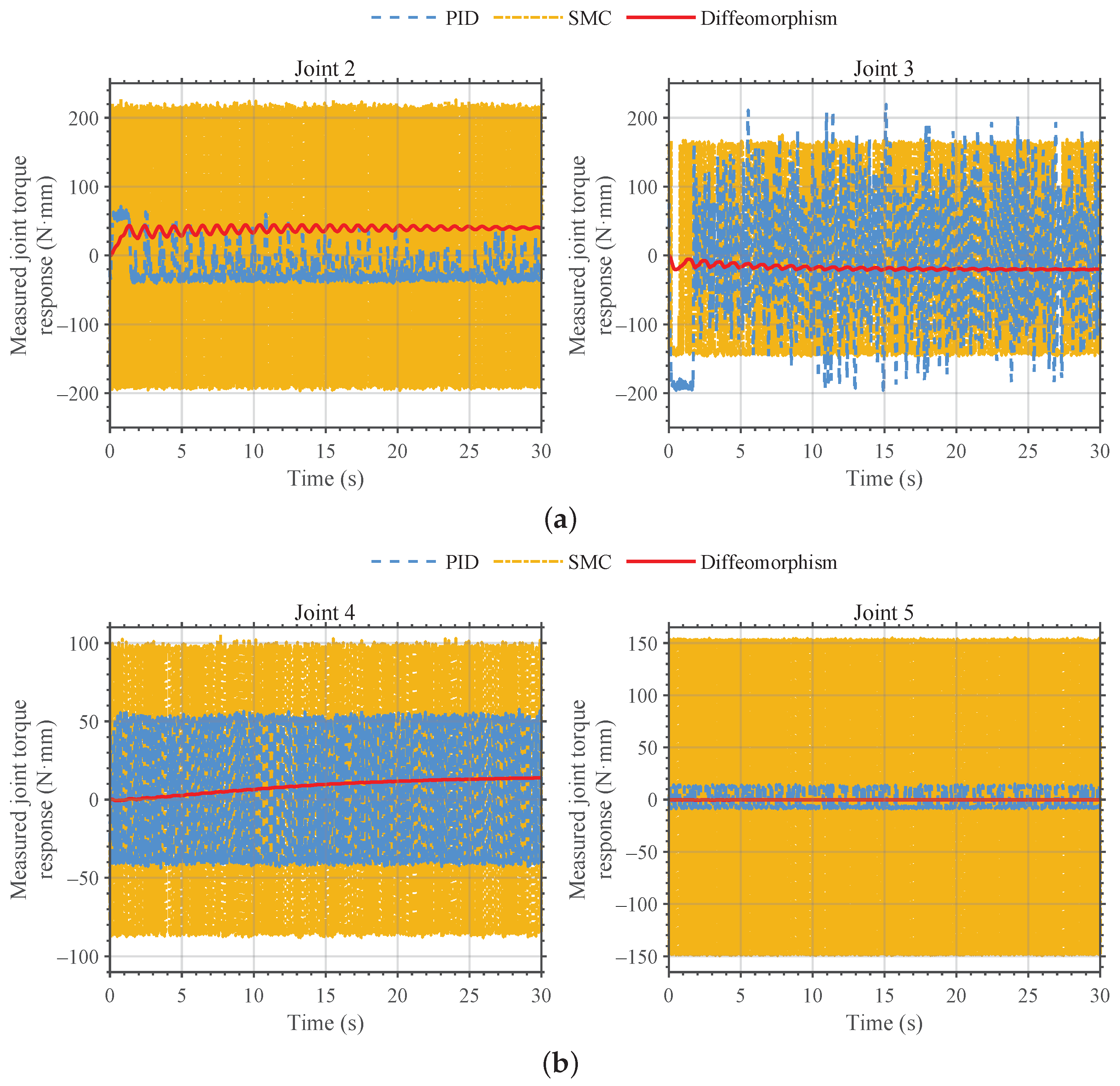
- PID reaches a peak measured joint torque response of 848.06 N·mm. SMC lowers the torque response but still violates the boundary. The proposed controller keeps the response at 80.78 N·mm with smoother dynamics.
- 3.
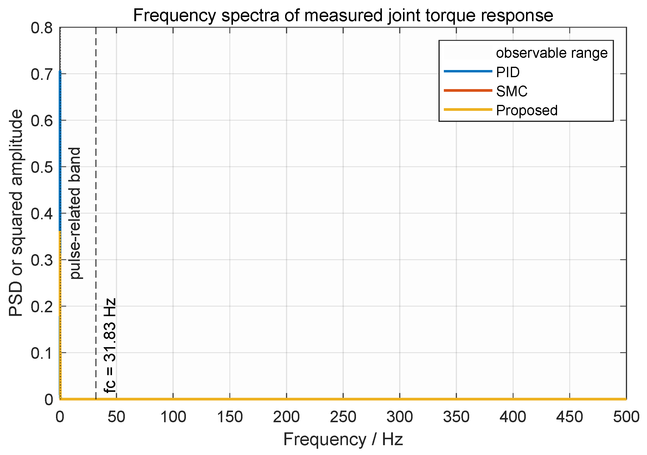
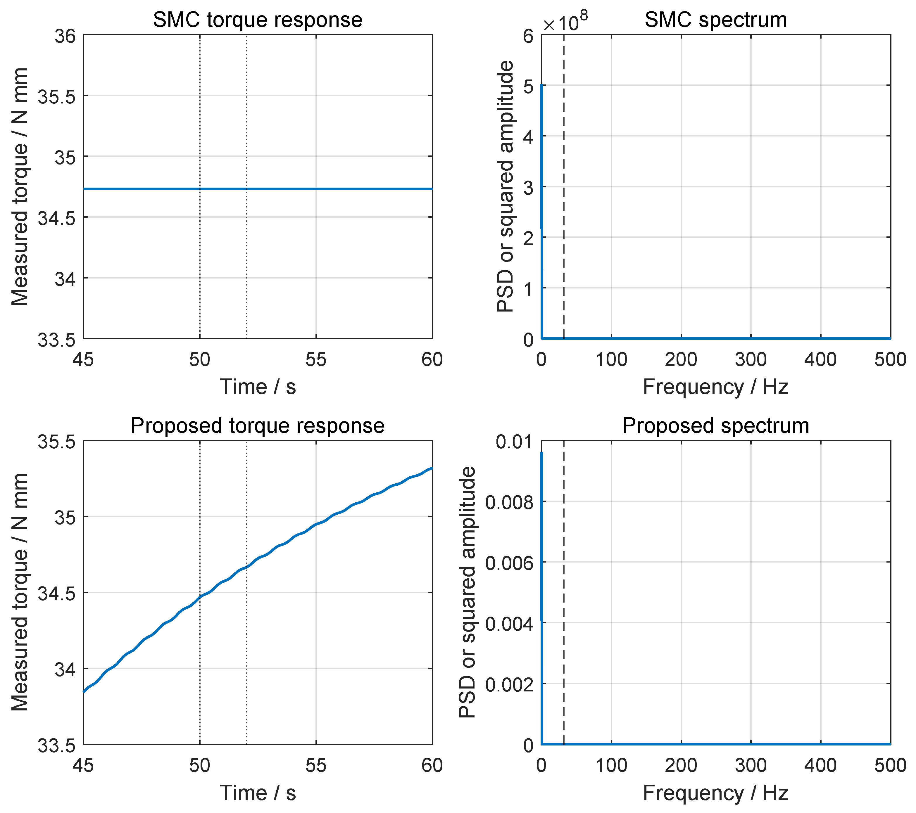
- The measured-channel spectral peak decreases from 42.22 dB under PID to 19.63 dB under SMC and 10.90 dB under the proposed controller.
3.2. Physical Boundary Protection and Transient Recovery Under Transient Pulse Compound Crosswind Disturbance
- 1.
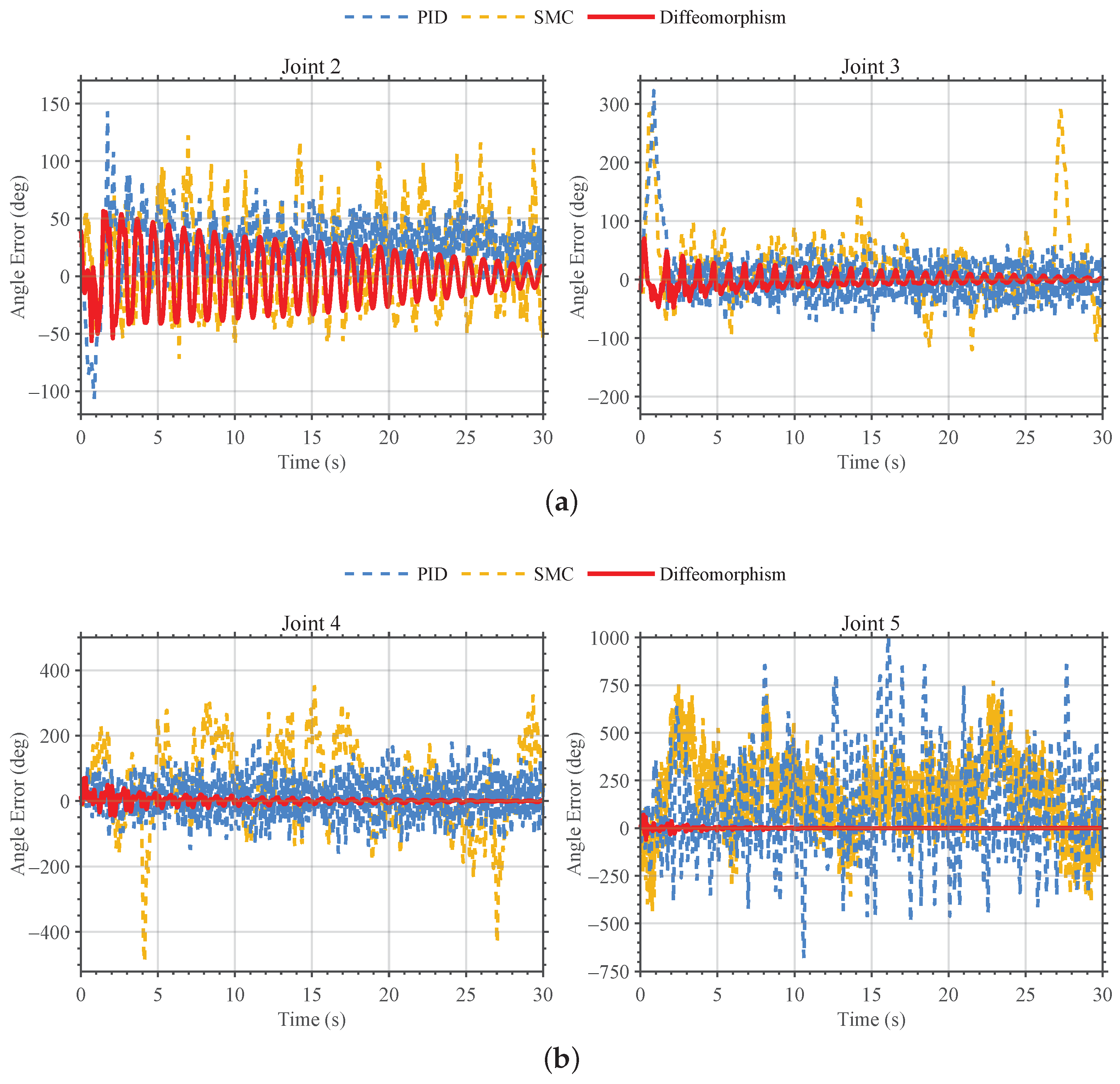
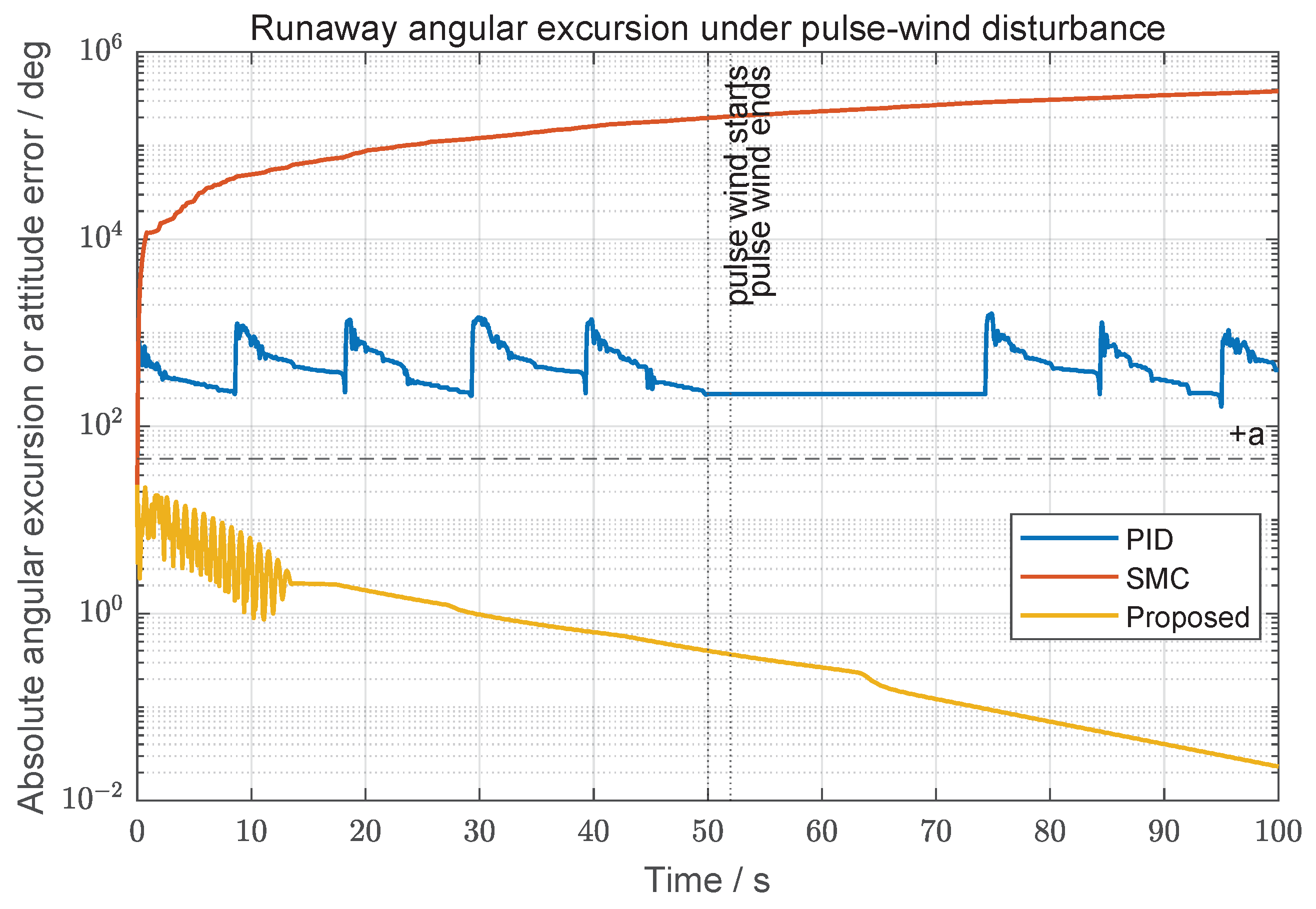
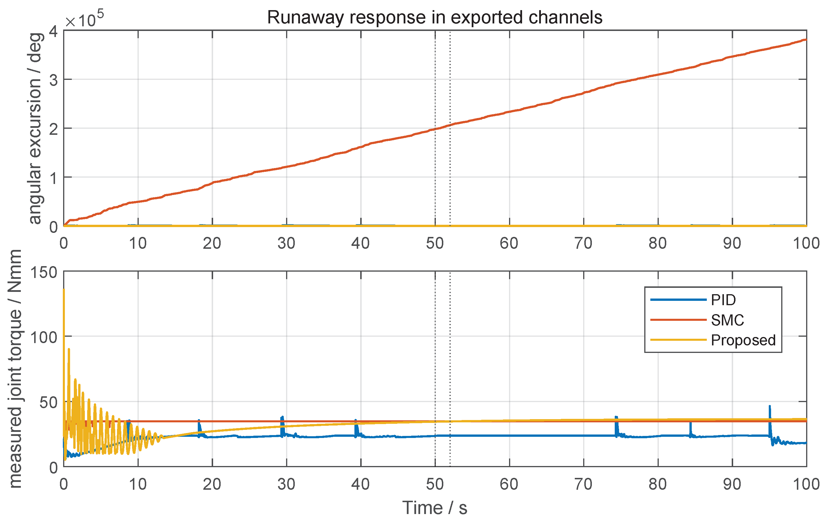
- Boundary protection. PID and SMC reach runaway unwrapped angular excursions of and , respectively. The proposed controller remains at with an RMSE of and no boundary violation.
- 2.
- Measured torque response. PID and SMC have lower peak measured torque responses, 46.42 and 34.73 N·mm, but these do not produce recovery. The proposed controller uses a bounded stabilizing response of 136.3 N·mm while maintaining safety.
- 3.
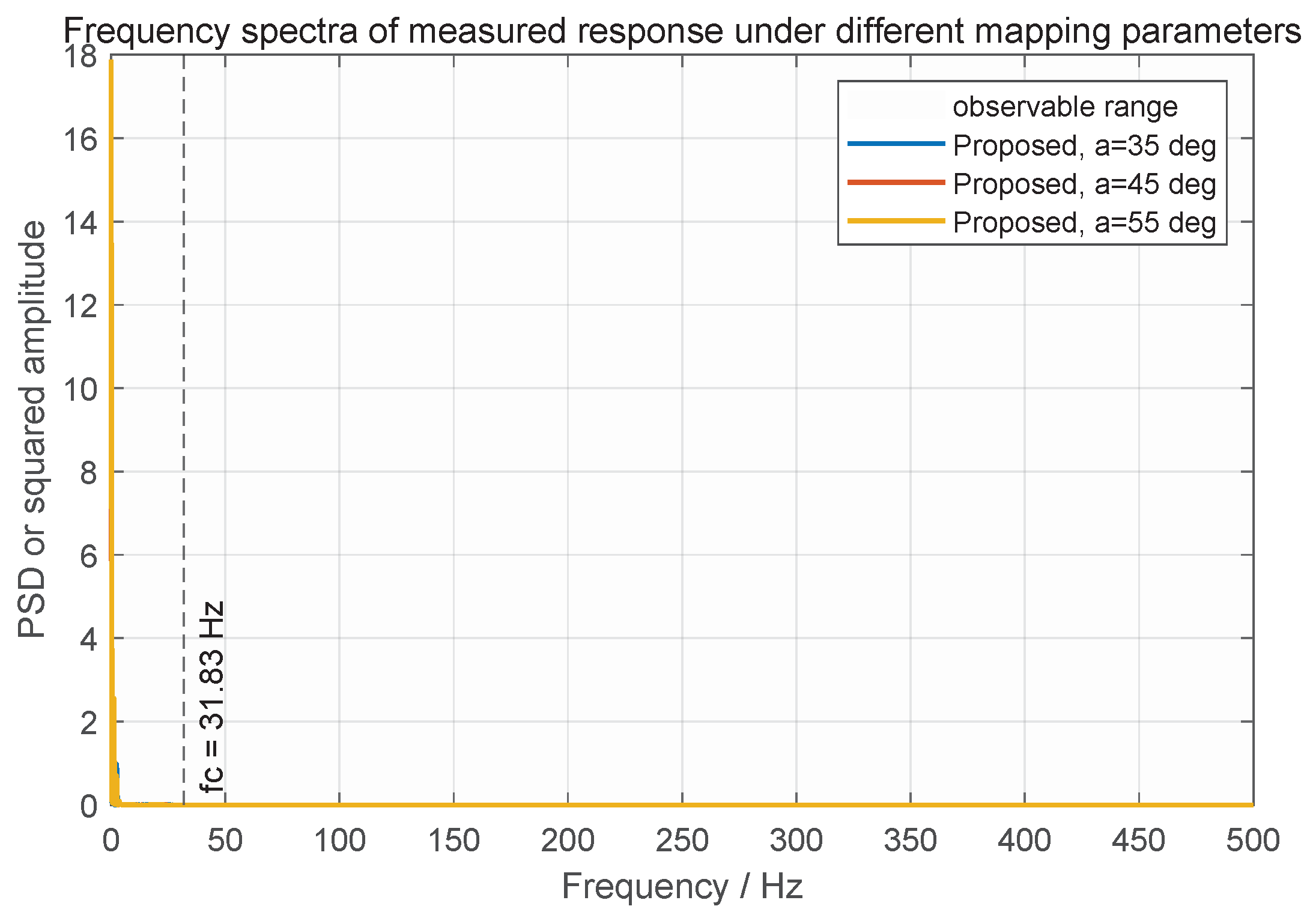
- Frequency-domain evidence. The frequency interpretation is restricted to exported feedback and torque-response channels. The supplemental spectra show lower measured-channel excitation for the proposed method without the runaway response seen in PID and SMC.
3.3. Statistical Robustness Analysis Based on Two-Dimensional Parameter Scanning
3.4. Sensitivity and Design Trade-Off Analysis of the Mapping Parameter a
3.5. Frequency-Domain, Sensitivity, and Baseline Analyses
3.5.1. Measured-Channel Frequency-Domain Evidence
3.5.2. Parameter Selection and Gain Sensitivity
3.5.3. Runaway Excursion and CBF-QP Baseline
4. Discussion
4.1. Computational Feasibility of the Diffeomorphic Mapping
4.2. Model Assumptions, Limitations, and Future Work
5. Conclusions
- 1.
- The diffeomorphism-based controller improves wind-free trajectory tracking. PID amplifies high-frequency measured-channel components from the flexible link, and SMC leaves residual oscillation and boundary violation. The proposed controller gives better convergence and smoother measured torque response.
- 2.
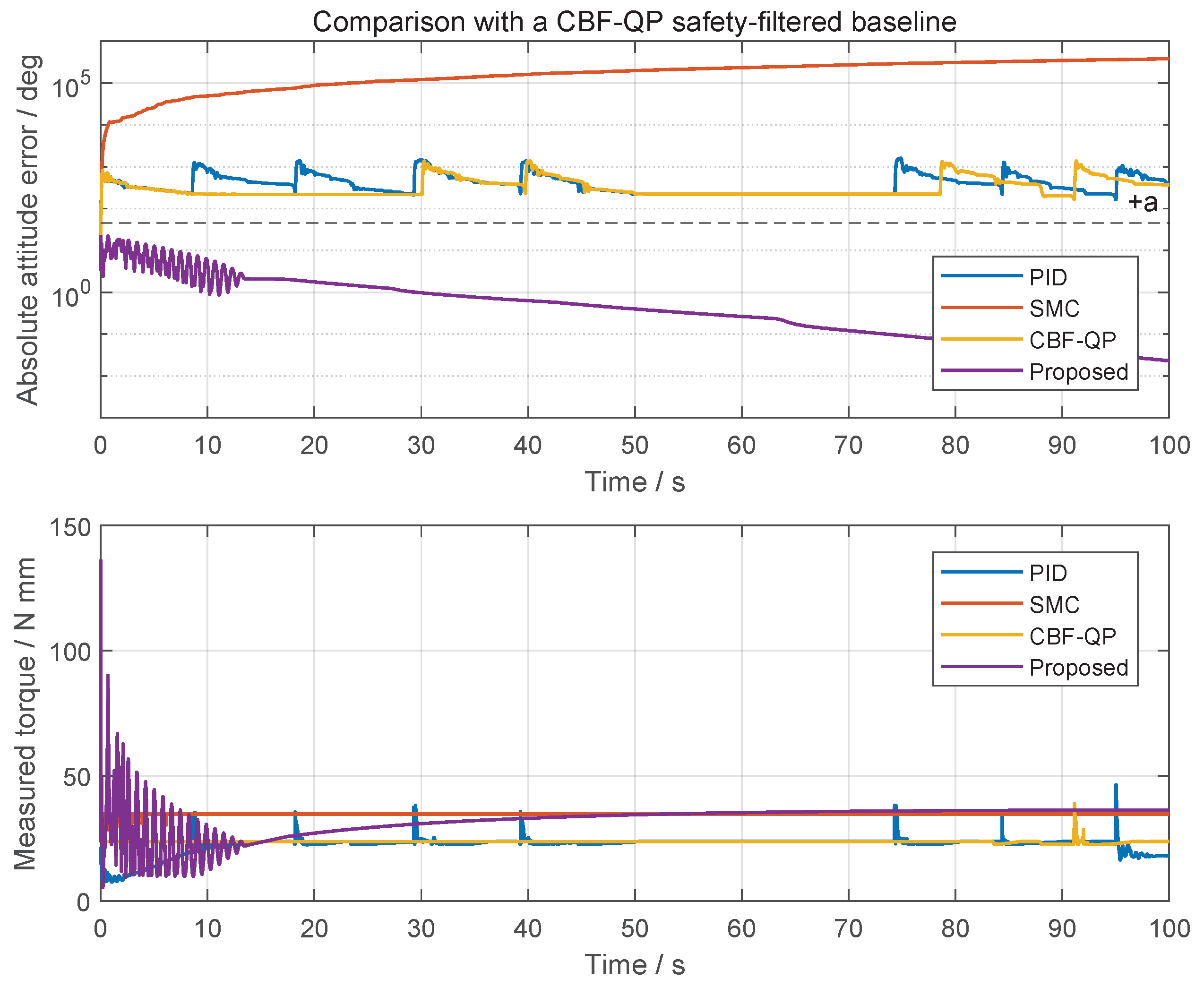
- The proposed method improves pulse wind disturbance rejection. Under a 2 m/s steady wind with a 1 m/s pulse, PID and SMC show runaway angular excursion and boundary violation. The CBF-QP safety-filtered PID baseline also violates the boundary, whereas the proposed controller remains bounded.
- 3.
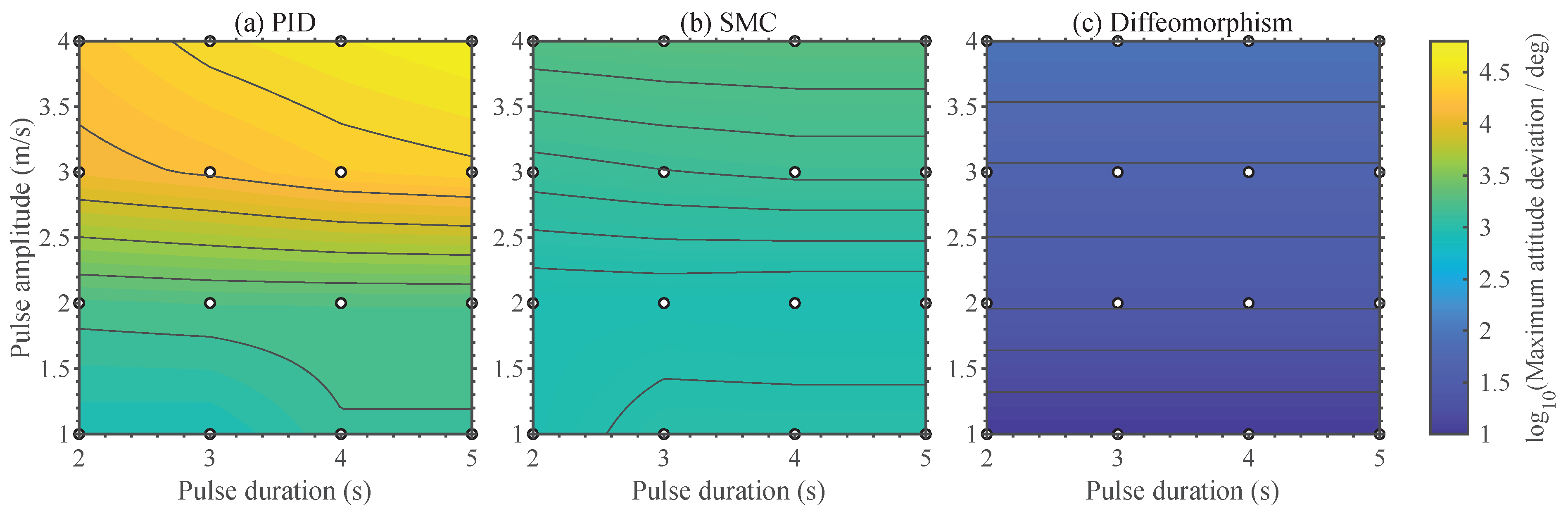
- The parameter scan verifies robustness across disturbance combinations. Across 16 pulse-amplitude and duration cases, PID degrades rapidly and SMC remains at high-error levels, while the proposed controller maintains lower error levels.
- 4.
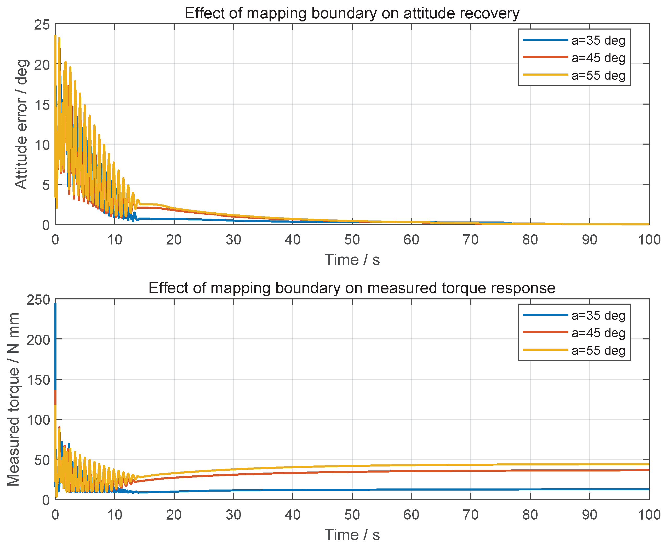
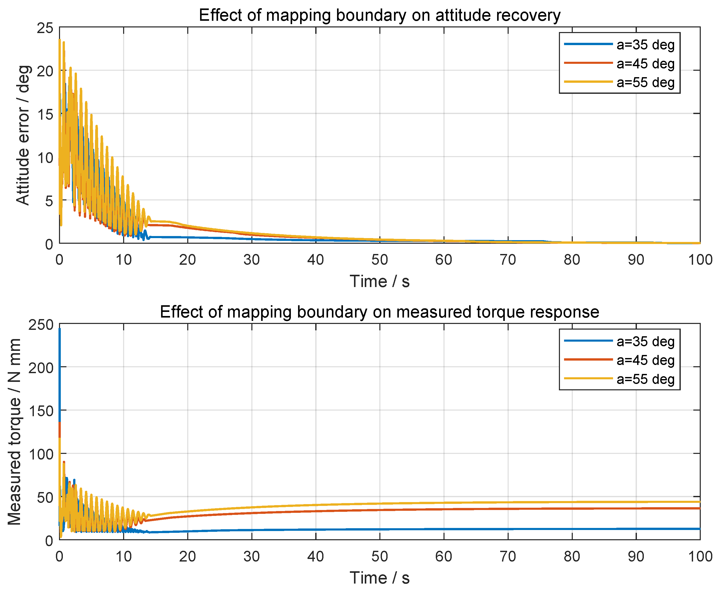
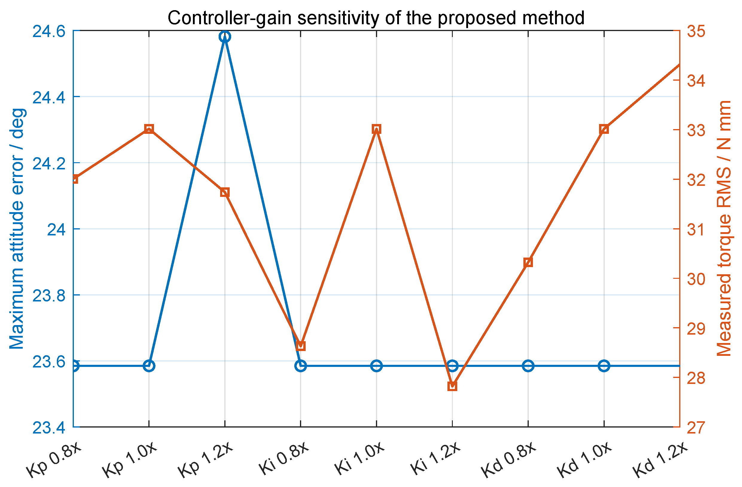
- The mapping parameter a mainly tunes measured torque response. For , , and , the boundary-protection conclusion is unchanged, but peak measured torque and torque RMS vary noticeably. Thus, a tunes the trade-off between boundary intensity and response-level torque variation.
- 5.
- The proposed controller gives the best overall simulation performance. Compared with PID, SMC, and CBF-QP safety-filtered PID baselines, it reduces attitude deviation, avoids boundary violation, and weakens high-frequency measured-channel influence under rigid–flexible coupling and wind disturbance.
Author Contributions
Funding
Data Availability Statement
Conflicts of Interest
Abbreviations
| ADAMS | Automatic Dynamic Analysis of Mechanical Systems |
| CFRP | Carbon Fiber Reinforced Polymer |
| FRP | Fiber Reinforced Polymer |
| MNF | Modal Neutral File |
| PID | Proportional–Integral–Derivative |
| SMC | Sliding Mode Control |
| RMSE | Root Mean Square Error |
| MMKS | Millimeter–Kilogram–Newton–Second unit system |
References
- Zufferey, R.; Tormo-Barbero, J.; Feliu-Talegn, D.; Rafee Nekoo, S.; Acosta, J.; Ollero, A. How ornithopters can perch autonomously on a branch. Nat. Commun. 2022, 13, 7713. [Google Scholar] [CrossRef] [Scilit] [PubMed]
- Wu, X.; Sun, W.; Sun, W.; Zhu, C.; Zhang, X. Research progress on autonomous landing methods for micro non-fixed-wing UAVs. Tech. Autom. Appl. 2024, 43, 1–6+23. [Google Scholar] [CrossRef]
- Zhang, C. Design and Dynamic Simulation of a Bionic Bird Autonomous Jumping Mechanism. Master Thesis, Shenyang Ligong University, Shenyang, China, 2024. [Google Scholar]
- Zufferey, R.; Tormo-Barbero, J.; Guzmn, M.M.; Maldonado, F.J.; Sanchez-Laulhe, E.; Grau, P.; Perez, M.; Acosta, J.; Ollero, A. Design of the high-payload flapping wing robot E-Flap. IEEE Robot. Autom. Lett. 2021, 6, 3097–3104. [Google Scholar] [CrossRef] [Scilit]
- Gomez-Tamm, A.E.; Perez-Sanchez, V.; Arrue, B.C.; Ollero, A. SMA actuated low-weight bio-inspired claws for grasping and perching using flapping wing aerial systems. In Proceedings of the IEEE/RSJ International Conference on Intelligent Robots and Systems (IROS), Las Vegas, NV, USA, 24 October–24 January 2021; pp. 1–6. [Google Scholar] [CrossRef] [Scilit]
- Zhang, C.; Shao, W.; Hao, Y. A bionic bird jumping grasping structure design based on stm32 development board control. Sci. Rep. 2024, 14, 10435. [Google Scholar] [CrossRef] [Scilit] [PubMed]
- Wang, B.; Yin, H.; Zi, P.; Xu, K.; Tian, Y.; Lyu, S.; Ding, X. Bionic bird claw design for grabbing and perching inspired by tendon-locking mechanism. IEEE Robot. Autom. Lett. 2024, 9, 8090–8097. [Google Scholar] [CrossRef] [Scilit]
- Broers, K.C.V.; Armanini, S.F. Design and testing of a bioinspired lightweight perching mechanism for flapping-wing MAVs using soft grippers. IEEE Robot. Autom. Lett. 2022, 7, 7526–7533. [Google Scholar] [CrossRef] [Scilit]
- Zhu, Y.; He, X.; Zhang, P.; Guo, G.; Zhang, X. Perching and grasping mechanism inspired by a bird claw. Machines 2022, 10, 656. [Google Scholar] [CrossRef] [Scilit]
- Nabi, F.G.; Sundaraj, K.; Vijean, V.; Shafiq, M.; Palaniappan, R.; Talib, I.; Rehman, H.U. A novel design of robotic hand based on bird claw model. J. Phys. Conf. Ser. 2021, 1997, 012034. [Google Scholar] [CrossRef] [Scilit]
- Guo, S.; Xu, Y.; Sun, W.; Liu, L. Under-Actuated Grasping Mechanical Arm Mechanism of Bird-like Arm Claw. Chinese Patent CN118024221A, 14 May 2024. [Google Scholar]
- Acosta, J.; Dria-Cerezo, A.; Fossas, E. Stabilisation of state-and-input constrained nonlinear systems via diffeomorphisms. Int. J. Robust Nonlinear Control 2018, 28, 4032–4044. [Google Scholar] [CrossRef] [Scilit]
- Acosta, J.; Dria-Cerezo, A.; Fossas, E. Diffeomorphism-based control of nonlinear systems subject to state constraints with actual applications. In Proceedings of the 2014 IEEE Conference on Control Applications (CCA), Juan Les Antibes, France, 8–10 October 2014; pp. 923–928. [Google Scholar] [CrossRef] [Scilit]
- Meng, Q.; Lai, X.; Yan, Z.; Wu, M. Tip position control and vibration suppression of a planar two-link rigid-flexible underactuated manipulator. IEEE Trans. Cybern. 2022, 52, 6771–6783. [Google Scholar] [CrossRef] [Scilit] [PubMed]
- Kim, D.W.; Kwak, M.K.; Kim, S.-M.; Feeny, B.F. Slewing and active vibration control of a flexible single-link manipulator. Actuators 2025, 14, 43. [Google Scholar] [CrossRef] [Scilit]
- Zhang, Q.; Zhao, X.; Liu, L.; Dai, T. Adaptive sliding mode neural network control and flexible vibration suppression of a flexible spatial parallel robot. Electronics 2021, 10, 212. [Google Scholar] [CrossRef] [Scilit]
- Feliu-Talegon, D.; Acosta, J.; Ollero, A. Control aware of limitations of manipulators with claw for aerial robots imitating bird’s skeleton. IEEE Robot. Autom. Lett. 2021, 6, 6426–6433. [Google Scholar] [CrossRef] [Scilit]
- Feliu-Talegon, D.; Acosta, J.; Suarez, A.; Ollero, A. A bio-inspired manipulator with claw prototype for winged aerial robots: Benchmark for design and control. Appl. Sci. 2020, 10, 6516. [Google Scholar] [CrossRef] [Scilit]
- Chattopadhyay, P.; Dikshit, H.; Majumder, A.; Ghoshal, S.; Maity, A. Dynamic analysis of a bio-inspired climbing robot using ADAMS-SIMULINK co-simulation. AIP Conf. Proc. 2018, 1952, 020015. [Google Scholar] [CrossRef] [Scilit]
- Liu, T.; Zhang, Z.; Liu, Y.; Fan, X. Motion simulation of bionic hexapod robot based on ADAMS/MATLAB co-simulation. J. Phys. Conf. Ser. 2020, 1601, 062032. [Google Scholar] [CrossRef] [Scilit]
- Shabana, A.A. Flexible multibody dynamics: Review of past and recent developments. Multibody Syst. Dyn. 1997, 1, 189–222. [Google Scholar] [CrossRef] [Scilit]
- Abbood, I.S.; Odaa, S.A.; Hasan, K.F.; Jasim, M.A. Properties evaluation of fiber reinforced polymers and their constituent materials used in structures—A review. Mater. Today Proc. 2021, 43, 1003–1008. [Google Scholar] [CrossRef] [Scilit]
- ACP Composites, Inc. Mechanical Properties of Carbon Fiber Composite Materials; Product Specification Reference Sheet; ACP Composites, Inc.: Livermore, CA, USA, 2012; Available online: https://acpcomposites.com/wp-content/uploads/2023/12/Mechanical-Properties-of-Carbon-Fiber-Composite-Materials.pdf (accessed on 8 July 2026).
- Craig, R.R.; Bampton, M.C.C. Coupling of substructures for dynamic analyses. AIAA J. 1968, 6, 1313–1319. [Google Scholar] [CrossRef] [Scilit] [PubMed]
- Langelaan, J.W.; Alley, N.; Neidhoefer, J. Wind field estimation for small unmanned aerial vehicles. In Proceedings of the AIAA Guidance, Navigation, and Control Conference, Toronto, ON, Canada, 2–5 August 2010. [Google Scholar] [CrossRef] [Scilit]
- Ames, A.D.; Xu, X.; Grizzle, J.W.; Tabuada, P. Control barrier function based quadratic programs for safety critical systems. IEEE Trans. Autom. Control 2017, 62, 3861–3876. [Google Scholar] [CrossRef] [Scilit]
- Utkin, V.I. Variable structure systems with sliding modes. IEEE Trans. Autom. Control 1977, 22, 212–222. [Google Scholar] [CrossRef] [Scilit]
- Mansour, T.; Konno, A.; Uchiyama, M. Modified PID control of a single-link flexible robot. Adv. Robot. 2008, 22, 433–449. [Google Scholar] [CrossRef] [Scilit]





| (a) Structural and inertial parameters | ||||||
| Link No. | ADAMS Part | Physical Meaning | /mm | /kg | /mm | /kg·mm2 |
| 1 | PART_2 | Bottom support and perching-contact segment | 30 | 0.0091609 | ||
| 2 | PART_3_flex | Flexible bio-inspired leg link | 120 | 0.0286896 | ||
| 3 | PART_4 | Intermediate attitude-regulation link | 150 | 0.0747856 | ||
| 4 | PART_5 | Upper attitude-regulation link | 60 | 0.0299142 | ||
| 5 | PART_6 | Distal attitude-regulation link | 50 | 0.0092363 | ||
| (b) Joint and actuation/constraint parameters | ||||||
| Link No. | ADAMS Part | Joint Type | Actuation/Constraint Parameters | |||
| 1 | PART_2 | Passive revolute joint; passive friction joint | FRICTION_1; , ; friction arm: 1.0 mm; pin radius: 9.0 mm; friction preload torque: 150 N·mm. | |||
| 2 | PART_3_flex | Active revolute joint; JOINT_2 | SFORCE_1; torque input: CTRL_T2. | |||
| 3 | PART_4 | Active revolute joint; JOINT_3 | SFORCE_1_2; torque input: CTRL_T3. | |||
| 4 | PART_5 | Active revolute joint; JOINT_4 | SFORCE_1_3; torque input: CTRL_T4. | |||
| 5 | PART_6 | Active revolute joint; JOINT_5 | SFORCE_1_4; torque input: CTRL_T5. | |||
| Mode Order | Circular Frequency /rad·s−1 | Natural Frequency f/Hz |
|---|---|---|
| 7 | 5868.66 | 933.55 |
| 8 | 5882.65 | 936.25 |
| 9 | 15,220.68 | 2422.45 |
| 10 | 15,270.15 | 2430.32 |
| 11 | 19,838.21 | 3157.35 |
| 12 | 31,855.43 | 5069.95 |
| Control Channel | ADAMS Input | Active Joint | Filter Coefficient N | |||
|---|---|---|---|---|---|---|
| PID Controller 1 | CTRL_T2 | Joint 2 | −2 | −0.05 | −0.05 | 10 |
| PID Controller 2 | CTRL_T3 | Joint 3 | −2 | −0.50 | −0.05 | 5 |
| PID Controller 3 | CTRL_T4 | Joint 4 | −3 | −0.50 | −0.01 | 1 |
| PID Controller 4 | CTRL_T5 | Joint 5 | −2 | −0.50 | −0.01 | 5 |
| Controller | Joint | Step | Limit | ||||
|---|---|---|---|---|---|---|---|
| SMC Controller 1 | Joint 2 | 2.0 | 40 | 10 | 15 | 0.01 | |
| SMC Controller 2 | Joint 3 | 2.0 | 40 | 10 | 10 | 0.01 | |
| SMC Controller 3 | Joint 4 | 2.0 | 40 | 10 | 10 | 0.01 | |
| SMC Controller 4 | Joint 5 | 2.5 | 5 | 15 | 6 | 0.01 |
| Controller | Input | Joint | ||||
|---|---|---|---|---|---|---|
| Diff PID 1 | CTRL_T2 | Joint 2 | −3.00 | −0.50 | −0.005 | 100 |
| Diff PID 2 | CTRL_T3 | Joint 3 | −3.00 | −0.50 | −0.025 | 100 |
| Diff PID 3 | CTRL_T4 | Joint 4 | −0.10 | −0.20 | −0.080 | 100 |
| Diff PID 4 | CTRL_T5 | Joint 5 | −0.10 | −0.10 | −0.010 | 100 |
| Category | Variable or Channel | Direction | Unit/Rate |
|---|---|---|---|
| Torque input | CTRL_T2–CTRL_T5 | Simulink to ADAMS SFORCE | N·mm, 1 kHz |
| Joint-angle feedback | VAR_Q2–VAR_Q5 | ADAMS to Simulink | deg, 1 kHz |
| Wind disturbance | Simulink disturbance model to torque summation | N·mm, 1 kHz | |
| Torque logs | ,, saturation flags | Simulink logging | N·mm, 1 kHz |
| Plant torque | JOINT_i.TZ or SFORCE_i.TZ | ADAMS result database to post-processing | N·mm |
| Flexible response | PART_3_flex modal | Optional ADAMS result export | mm |
| Item | Setting |
|---|---|
| Plant model | Bird_5Link; PART_3_flex |
| Unit system | MMKS: mm, kg, N, s, deg |
| Flexible-body modes | 1108 nodes; 24 modes; retained elastic modes 7–24 |
| Passive joint | JOINT_1 with FRICTION_1; preload torque 150 N·mm |
| Active torque interface | CTRL_T2–CTRL_T5 driving ADAMS SFORCE elements |
| Communication step | s; nominal data-exchange rate 1 kHz |
| Feedback conditioning | Memory block plus low-pass filter |
| Mechanical hard stop | No explicit hard-stop element in the exported ADAMS text model |
| Actuator saturation | Simulink-side saturation before ADAMS input; nominal bound N·mm |
| Controller/Interface | Torque Bound | Location |
|---|---|---|
| PID | N·mm per active joint | Before CTRL_T2–CTRL_T5 |
| SMC | N·mm per active joint | Before ADAMS input |
| Proposed | N·mm per active joint | After mapped-error controller and before ADAMS input |
| ADAMS SFORCE interface | No independent actuator limit | ADAMS plant side |
| Performance Metric | Conventional PID | SMC | Proposed Diffeomorphism |
|---|---|---|---|
| Settling time /s | Not converged | Not converged | 28.31 |
| Maximum attitude deviation error/° | 848.06 | 187.23 | 41.00 |
| RMSE/° | 137.70 | 27.62 | 7.25 |
| Recovery time /s | Not recovered | Not recovered | 27.54 |
| Peak measured joint torque response/N·mm | 848.06 | 40.00 | 80.78 |
| Constraint violation | Yes | Yes | No |
| Measured-channel spectral peak/dB | 42.22 | 19.63 | 10.90 |
| Performance Metric | Conventional PID | SMC | Proposed Diffeomorphism |
|---|---|---|---|
| Settling time /s | Not converged | Not converged | 6.15 |
| Maximum angular excursion/° | 1602.56 | 381,330.03 | 23.58 |
| RMSE/° | 491.7 | 224,400 | 2.943 |
| Recovery time /s | Not recovered | Not recovered | 0 |
| Peak measured joint torque response/N·mm | 46.42 | 34.73 | 136.3 |
| Constraint violation | Yes | Yes | No |
| Frequency-domain evidence | See Table 12 | See Table 12 | See Table 12 |
| Performance Metric | |||
|---|---|---|---|
| Maximum angular excursion/° | 23.58 | 23.58 | 23.58 |
| RMSE/° | 2.829 | 2.943 | 3.251 |
| Recovery time /s | 0 | 0 | 0 |
| Peak measured joint torque response/N·mm | 244.5 | 136.3 | 117.9 |
| Torque RMS/N·mm | 14.32 | 33.02 | 39.74 |
| Saturation duration/s | 0.994 | 1.098 | 1.683 |
| Constraint violation | No | No | No |
| High-frequency torque PSD integral | 482.2 | 106.5 | 66.19 |
| Case | Interval | Frequency/Hz | Peak Amplitude |
|---|---|---|---|
| Proposed, | 0–100 s | 1.221; 2.441; 3.662 | 0.1302; 0.9692; 0.02492 |
| Proposed, | 0–100 s | 1.221; 2.441; 3.662 | 1.675; 0.5395; 0.05749 |
| Proposed, | 0–100 s | 1.221; 2.441; 3.662 | 2.553; 0.6949; 0.0854 |
| PID | 45–60 s | 0.488; 0.684; 0.879 | 0.004879; 0.002807; 0.001397 |
| SMC | 45–60 s | 0.244; 0.488; 0.732 | near noise floor |
| Proposed, nominal | 45–60 s | 1.221 |
| Case | Varied | Max./deg | RMSE/deg | Peak Torque | RMS | Sat./s | Violation | PSD |
|---|---|---|---|---|---|---|---|---|
| a | 23.58 | 2.829 | 244.5 | 14.32 | 0.994 | No | 482.2 | |
| a | 23.58 | 2.943 | 136.3 | 33.02 | 1.098 | No | 106.5 | |
| a | 23.58 | 3.251 | 117.9 | 39.74 | 1.683 | No | 66.19 | |
| 0.8× | 23.58 | 3.314 | 118.5 | 32.00 | 0.961 | No | 75.72 | |
| 1.0× | 23.58 | 2.943 | 136.3 | 33.02 | 1.098 | No | 106.5 | |
| 1.2× | 24.58 | 2.922 | 154.8 | 31.74 | 1.241 | No | 150.5 | |
| 0.8× | 23.58 | 2.866 | 136.3 | 28.63 | 0.887 | No | 113.8 | |
| 1.0× | 23.58 | 2.943 | 136.3 | 33.02 | 1.098 | No | 106.5 | |
| 1.2× | 23.58 | 2.753 | 136.3 | 27.82 | 0.882 | No | 115.6 | |
| 0.8× | 23.58 | 2.893 | 127.6 | 30.32 | 0.900 | No | 100.8 | |
| 1.0× | 23.58 | 2.943 | 136.3 | 33.02 | 1.098 | No | 106.5 | |
| 1.2× | 23.58 | 2.933 | 145.7 | 34.32 | 1.181 | No | 117.2 |
| Controller | Maximum Unwrapped Angular Excursion | Boundary Violation | Physical Meaning |
|---|---|---|---|
| PID | 1602.56° | Yes | Runaway angular excursion after loss of stability; no mechanical hard stop is defined in the exported plant. |
| SMC | 381,330.03° | Yes | Runaway angular excursion after loss of stability; the value is not a normal bounded attitude error. |
| Proposed | 23.58° | No | Bounded response inside the prescribed safety boundary in the exported log. |
| Controller | Violation | RMSE | Max. Excursion/Peak Torque | Interpretation |
|---|---|---|---|---|
| PID | Yes | 491.7 | 1603°/46.42 N·mm | Unconstrained baseline; boundary is lost after disturbance. |
| SMC | Yes | deg/34.73 N·mm | Switching baseline; command bound alone does not prevent runaway rotation. | |
| Safety-filtered PID | Yes | 577 | 1394°/38.99 N·mm | Constraint-aware filter is insufficient under the torque-limited rerun condition. |
| Proposed | No | 2.943 | 23.58°/136.3 N·mm | Boundary-aware error reshaping keeps the response inside the prescribed limit. |
Disclaimer/Publisher’s Note: The statements, opinions and data contained in all publications are solely those of the individual author(s) and contributor(s) and not of MDPI and/or the editor(s). MDPI and/or the editor(s) disclaim responsibility for any injury to people or property resulting from any ideas, methods, instructions or products referred to in the content. |
© 2026 by the authors. Licensee MDPI, Basel, Switzerland. This article is an open access article distributed under the terms and conditions of the Creative Commons Attribution (CC BY) license.
Share and Cite
Rong, G.; Yang, J.; Chen, J.; Wang, J.; Wang, J. Dynamics Modeling of a Rigid–Flexible Coupled Flapping-Wing Robot and Diffeomorphism-Based Disturbance Rejection Attitude-Constrained Control. Aerospace 2026, 13, 632. https://doi.org/10.3390/aerospace13070632
Rong G, Yang J, Chen J, Wang J, Wang J. Dynamics Modeling of a Rigid–Flexible Coupled Flapping-Wing Robot and Diffeomorphism-Based Disturbance Rejection Attitude-Constrained Control. Aerospace. 2026; 13(7):632. https://doi.org/10.3390/aerospace13070632
Chicago/Turabian StyleRong, Guang, Jingyuan Yang, Jinbao Chen, Jian Wang, and Jianyuan Wang. 2026. "Dynamics Modeling of a Rigid–Flexible Coupled Flapping-Wing Robot and Diffeomorphism-Based Disturbance Rejection Attitude-Constrained Control" Aerospace 13, no. 7: 632. https://doi.org/10.3390/aerospace13070632
APA StyleRong, G., Yang, J., Chen, J., Wang, J., & Wang, J. (2026). Dynamics Modeling of a Rigid–Flexible Coupled Flapping-Wing Robot and Diffeomorphism-Based Disturbance Rejection Attitude-Constrained Control. Aerospace, 13(7), 632. https://doi.org/10.3390/aerospace13070632