2. Literature Review
A supersonic aircraft represents the pinnacle of aerospace engineering, designed to exceed the speed of sound (Mach 1) while maintaining aerodynamic stability, fuel efficiency, and passenger comfort. However, the development of such aircraft has historically faced challenges in terms of balancing performance with safety, economic viability, and environmental impact. The Concorde and Tupolev Tu-144 were the first commercial supersonic aircraft, proving the feasibility of supersonic transport; however, some critical limitations were exposed, including high fuel consumption, limited range, and excessive noise pollution from sonic booms [
1].
Recent advancements in materials, propulsion systems, and aerodynamic design have attracted interest in supersonic flight. NASA’s X-59 QueSST project, for example, addresses noise pollution concerns by focusing on low-boom supersonic travel and leveraging cutting-edge designs and technology to minimize sonic boom disturbances [
2]. Similarly, Boom Supersonic’s Overture Aircraft aims to combine speed and sustainability through innovative aerodynamics and the adoption of sustainable aviation fuel (SAF) [
11]. These modern approaches underscore the industry’s commitment to addressing the environmental and operational challenges of supersonic travel.
The SA-24 Phoenix, a conceptual supersonic transport aircraft, was designed to overcome these challenges by integrating advanced safety systems, such as ZSA, and employing state-of-the-art tools such as CAD and MBSE. With a passenger capacity of 50 and a cruising speed of Mach 1.8, SA-24 aims to demonstrate advanced approaches to supersonic safety, efficiency, and regulatory compliance. Previous conceptual design studies on low-boom supersonic transport aircraft have demonstrated the importance of multidisciplinary optimisation in achieving performance and regulatory compliance [
12].
2.1. Zonal Safety Analysis Framework in Conceptual Design
Recent studies have explored the integration of MBSE approaches within aircraft fuel system development to improve subsystem coordination and maintenance-oriented system analysis during early design stages [
13]. Unlike conventional system-specific safety analyses, the ZSA examines potential hazards within specific aircraft zones, focusing on how subsystem interactions and environmental factors contribute to safety risks [
5]. For instance, fuel tanks placed near high-temperature zones or electrical systems pose inherent risks such as vapor ignition or leakage.
The ZSA methodology involves identifying hazards, assessing their likelihood and impact, and implementing mitigation measures [
5,
6]. The ZSA aligns closely with regulatory frameworks, such as EASA CS-25 and FAA Part 25, which emphasize the need for redundancy, fault tolerance, and safe design practices [
14]. By integrating ZSA during the early stages of design, engineers can proactively address spatial safety concerns, ensuring compliance with airworthiness standards.
The ZSA is applied in aerospace engineering to assess fuel systems, environmental control systems (ECSs), and avionics. For example, Airbus employs ZSA to evaluate the placement of fuel lines relative to electrical wiring, thereby minimizing fire risks in the A320neo series [
15]. Similarly, Boeing’s use of ZSA, combined with digital twin simulations, enables the prediction and mitigation of subsystem failures in the 787 Dreamliner [
16]. However, conventional ZSA methodologies often rely on expert judgment and static diagrams, thereby limiting their scalability. Integrating the ZSA with tools, such as CAD and MBSE, can help address these challenges by enabling dynamic simulations and iterative hazard assessments.
2.2. Fundamentals of Model-Based Systems Engineering (MBSE)
MBSE facilitates the representation and simulation of the functional, behavioral, and structural aspects of systems through a model-driven approach [
8,
9]. By shifting away from document-based processes, MBSE enables engineers to dynamically simulate interactions between subsystems, thereby providing a holistic view of aircraft performance and safety. Tools, such as the Cameo Systems Modeler and Enterprise Architect, are instrumental in creating digital twins of complex systems, which can then be used to evaluate the performance under a variety of operational scenarios [
10].
For SA-24 Phoenix, MBSE enables dynamic hazard analyses, such as simulating fuel vaporization scenarios caused by thermal expansion or failures in fuel system venting. Recent MBSE research has emphasized the digitalization of aircraft design processes through improved integration between requirements management, system architecture models, and engineering workflows [
17]. Moreover, the ability of MBSE to trace requirements to functional and structural models ensures compliance with regulatory standards, thereby enhancing the overall design process.
2.3. Conceptual CAD Modeling in Aircraft Design
CAD tools, such as computer-aided three-dimensional interactive application (CATIA) and 3DEXPERIENCE, allow engineers to design, visualize, and simulate the spatial configurations of aircraft systems [
3,
4]. For supersonic aircraft, such as the SA-24 Phoenix, CAD is indispensable for analyzing thermal loads, structural stresses, and spatial constraints, particularly in high-risk zones such as fuel tanks [
4]. The capability to model complex geometries and simulate environmental conditions allows engineers to optimize designs for both performance and safety [
3,
4].
MBSE-based aircraft architecting approaches enable structured requirement analysis and system-level integration during conceptual aircraft development [
18]. CAD enables interference checks between systems, ensuring that components, such as venting mechanisms, sensors, and pipelines, are optimally positioned to minimize risk. Beyond spatial modeling, CAD also supports material analysis, allowing engineers to select materials that can withstand the high temperatures and pressures associated with supersonic flight.
2.4. Integration of CAD and MBSE Models
The integration of CAD and MBSE represents an increasingly important approach in conceptual aircraft design and multidisciplinary aerospace system development [
19,
20], combining spatial subsystem representation with functional system analysis. Recent studies have demonstrated the broader applicability of MBSE methodologies across aircraft lifecycle activities, including maintenance planning and operational optimization [
21].
This integration also facilitates iterative analyses, allowing for real-time adjustments to the design. For instance, if a CAD model identifies thermal hotspots in a fuel tank, the MBSE can simulate the impact of these hotspots on system behavior, such as fuel vaporization and venting efficiency. By iterating between these tools, engineers can proactively optimize the design and address hazards. In addition, the combination of CAD and MBSE supports the creation of comprehensive safety reports, which can be used to streamline regulatory approval and enhance stakeholder communication.
2.5. Applications in Supersonic Aircraft Design
Supersonic aircraft require innovative safety and design methodologies due to their extreme operational environments. Historical examples, such as the Concorde, underscore the importance of robust safety frameworks, particularly in zones prone to cascading failures, such as fuel systems [
22]. The lessons learned from the Concorde’s fuel tank issues, including incidents of structural compromise during high-speed operations, highlight the necessity for advanced tools for hazard identification.
Modern projects, such as NASA’s X-59 and Boom Supersonic Overture, illustrate how advanced digital tools, such as CAD and MBSE, enhance safety and efficiency. These projects integrate early-stage safety analyses into their workflows to ensure that hazards are identified and mitigated before physical prototypes are built. SysML-based MBSE approaches have increasingly been applied in aviation system design to support functional modeling, system architecture development, and requirement traceability [
23]. The ability to model and simulate real-world conditions before manufacturing reduces costs and enhances design confidence, particularly in novel aircraft configurations.
2.6. Environmental Considerations
The environmental impact of supersonic aircraft is a major concern, particularly in terms of noise pollution and greenhouse gas emissions. Innovations in low-boom technology, such as those implemented in the NASA X-59 project, have addressed noise concerns by significantly reducing the intensity of sonic booms [
24]. These advancements have paved the way for a broader public acceptance of supersonic transport.
The adoption of SAF is another critical step toward reducing the environmental footprint of supersonic flights. SAF offers a viable alternative to conventional jet fuels, reduces lifecycle greenhouse gas emissions, and aligns with global sustainability goals [
11]. Integrating SAF into the SA-24 Phoenix design not only enhances environmental credentials, but also ensures compliance with evolving regulatory requirements.
2.7. Gaps in Current Zonal Hazard Analysis Techniques
Despite the significant progress in aerospace safety methodologies, notable gaps remain in the literature. Most studies focused on CAD and MBSE as standalone tools, neglecting their combined application in comprehensive safety analyses [
8,
19]. Further, the lack of standardized protocols for integrating these tools poses challenges to their widespread adoption.
This study aimed to address these gaps by proposing a unified framework tailored for supersonic aircraft, specifically focusing on the fuel tank system of SA-24 Phoenix. By leveraging the strengths of CAD and MBSE, the proposed framework seeks to help proactively identify hazards, optimize design efficiency, and enhance compliance with safety regulations.
In parallel with model-based approaches, recent studies have explored data-driven fault diagnosis techniques using machine learning to identify and predict system failures in complex engineering systems. Approaches such as explainable artificial intelligence and transfer learning-based fault diagnosis have demonstrated effectiveness in capturing nonlinear system behavior and improving fault detection accuracy. However, these methods typically rely on large datasets and are more applicable to operational or post-design phases.
In contrast, the present study focuses on model-based hazard identification during the conceptual design phase, where system data are limited. Therefore, data-driven and model-based approaches can be considered complementary, with potential integration in future digital engineering frameworks for enhanced lifecycle safety analysis [
25,
26,
27].
2.7.1. Limitations of Conventional Zonal Safety Analysis
Conventional ZSA methodologies primarily focus on evaluating hazards associated with subsystem installations within predefined aircraft zones. However, these methods often rely on the manual interpretation of engineering drawings and system documentation, which may limit their ability to fully capture the complex interactions between aircraft subsystems.
The separation between spatial subsystem models and system architecture representations can make it difficult to identify hazards arising from the interaction between component placement and system behavior. As aircraft systems become more tightly integrated, these limitations highlight the need for modeling frameworks that combine geometric subsystem configurations with system architecture modeling.
2.7.2. Regulatory Evolution in Supersonic Aircraft Certification
Aircraft certification frameworks are continuously evolving to address emerging aircraft technologies and operational concepts. Conventional large-transport aircraft certification has historically been governed by regulations, such as the European Union Aviation Safety Agency Certification Specification CS-25, which defines airworthiness standards for transport category aircraft. However, renewed interest in commercial supersonic transport has prompted regulatory authorities to develop updated certification requirements that specifically address the design and operation of supersonic aircraft.
The forthcoming European Union Aviation Safety Agency Certification Specification CS-25 Amendment 27 is expected to introduce additional guidelines related to supersonic aircraft performance, environmental impact, and safety considerations. These developments reflect the increasing complexity of advanced aircraft architectures and the need for more integrated safety analysis during early design stages.
Early-stage hazard identification frameworks that combine CAD and MBSE have the potential to support these evolving certification processes by enabling engineers to identify subsystem interaction risks during conceptual design. Integrating spatial system models with functional system architectures can help improve traceability between design decisions and safety requirements, thereby facilitating more efficient safety validation during certification activities.
2.8. Concluding Remarks
Integrating CAD and MBSE can help significantly enhance ZSA processes in aerospace design. However, most existing studies have examined these tools independently rather than as an integrated framework for early hazard identification during conceptual aircraft design. This gap is particularly important for complex systems, such as supersonic aircraft fuel tanks, where spatial subsystem interactions can introduce cascading safety risks.
To address this limitation, this paper proposes an integrated CAD–MBSE modeling framework to conduct early-stage zonal hazard analysis and dynamic safety analysis during conceptual aircraft design. The framework was applied to the fuel tank system of the SA-24 Phoenix supersonic aircraft to demonstrate how spatial subsystem modeling and functional system architecture analysis can be combined to improve early hazard detection and mitigation. By demonstrating the feasibility of this methodology for supersonic aircraft, this study provides a scalable framework for designing safety-critical systems. The findings will contribute toward advancing the field of aerospace engineering by ensuring both safety and sustainability of future supersonic transport.
3. Methodology
3.1. Research Design
The methodology used in this study integrates CAD and MBSE into a unified framework for ZSA. This approach is specifically tailored for the SA-24 Phoenix supersonic aircraft, focusing on the safety and performance of its fuel tank system. By leveraging the precise spatial capabilities of CAD and the dynamic functional insights of MBSE, the methodology enables comprehensive hazard identification, design optimization, and compliance with regulatory requirements such as EASA CS-25 [
14]. This structured framework emphasizes an iterative design and analysis, allowing for the seamless incorporation of safety considerations throughout the development process.
The CAD and MBSE tools employed in this study were used during the conceptual aircraft design phase to support early hazard identification, rather than to provide formal certification. In accordance with established aerospace safety assurance frameworks, such as RTCA DO-178C, the software used during the conceptual design typically operates at a lower assurance level, not as certified flight-critical software. Therefore, the modeling tools utilized in this research correspond conceptually to a Design Assurance Level C equivalent, which is appropriate for analytical tools used to support hazard identification and design exploration, rather than direct certification verification. The software tools and their corresponding conceptual assurance levels used in this study are summarized in
Table 1.
All the CAD and MBSE analyses were conducted using the Dassault Systèmes and MBSE modeling tools available at Cranfield University. The modeling activities were conducted using CATIA V5-6R2023 within the 3DEXPERIENCE R2023x platform environment and Cameo Systems Modeler 2021, representing the software configuration available through the Cranfield University Digital Engineering Laboratory. Modeling tools were used to support conceptual design analysis and hazard identification activities rather than certification-grade verification simulations. The conceptual design framework adopted in this study is aligned with the GENUS multidisciplinary aircraft design environment developed at Cranfield University [
28].
3.2. Preliminary System Definition
The first step in this methodology involves defining the scope of the system, the operational parameters, and the constraints. This process begins with an extensive review of existing data on supersonic aircraft, such as the Concorde and Boom Supersonic Overture, to identify design principles and historical challenges. Regulatory standards, including EASA CS-25 [
29], were analyzed to establish safety benchmarks relevant to fuel tank systems. This ensures that the design adheres to industry norms, while addressing the unique challenges associated with supersonic flight.
The mapping of critical components, such as fuel pipelines, venting systems, and structural insulation, forms a core part of this phase. The interdependencies between the fuel tank and other subsystems, such as propulsion and environmental controls, were identified to ensure that these interactions did not introduce new risks. Performance metrics, including thermal resilience, structural integrity, and fuel efficiency, were also defined at this stage. These metrics guide the subsequent design and safety analysis processes to ensure the alignment of functional and safety objectives.
3.3. CAD Model Development
In the second phase, detailed CAD models of the fuel tank system were developed using the 3DEXPERIENCE platform. This phase focused on creating accurate geometric representations of the system and simulating its performance under real-world conditions. The design process incorporates spatial constraints within the aircraft fuselage and ensures the optimal placement of components for operational and maintenance efficiency.
Thermal simulations showed that the fuel temperature remained within acceptable conceptual operating limits during the analyzed supersonic cruise conditions. This analysis identifies potential vulnerabilities, such as material fatigue or thermal expansion, which can compromise the integrity of the system.
The thermal simulations conducted in this study represent a first-order conceptual thermal assessment intended to evaluate potential subsystem thermal interactions during early aircraft design. The thermal boundary conditions applied in the model were derived from representative aerodynamic heating estimates reported in the literature for a supersonic transport aircraft operating in the Mach 1.5–1.8 flight regime.
To provide a clearer physical basis for the conceptual thermal analysis, simplified governing relations were considered. These relations are presented as simplified governing equations used for first-order conceptual hazard analysis during early-stage aircraft design. Heat conduction within structural materials can be expressed as:
where
q represents heat flux,
k is the thermal conductivity, and ∇
T is the temperature gradient. Convective heat transfer between the aircraft surface and surrounding airflow can be approximated as:
where
h is the convective heat transfer coefficient and
A is the exposed surface area.
In addition, fuel vapor behavior under elevated temperature conditions can be approximated using the ideal gas relation:
The use of the ideal gas relation assumes a simplified closed-system behavior with uniform thermodynamic properties, which is appropriate for conceptual-level estimation but does not capture transient or non-ideal fluid effects. These first-order relations provide a conceptual basis for estimating thermal loads and pressure behavior within the fuel system during supersonic cruise conditions. It is noted that high-fidelity modelling using computational fluid dynamics or detailed thermodynamic analysis is beyond the scope of the present conceptual design study.
Typical supersonic transport aircraft operating at Mach numbers between 1.5 and 1.8 may experience external structural temperatures in the range of approximately 100–150 °C, depending on flight altitude and aerodynamic configuration [
3].
The applied skin temperature range of approximately 110–130 °C therefore represents a simplified engineering approximation used to evaluate the influence of external structural heating on nearby fuel system components. These simulations were performed using CAD-based thermal modeling tools to support subsystem layout evaluation and hazard identification, rather than to provide high-fidelity aerodynamic heating predictions that would normally require a computational fluid dynamics (CFD) analysis.
The boundary conditions and modeling parameters used during the thermal simulation analysis are summarized in
Appendix A.
Structural stress analyses complement these simulations by identifying and addressing weak points in the design. Spatial interference checks ensure that components, such as pipelines and sensors, are positioned to avoid mechanical conflicts, thereby enhancing the reliability and functionality of the system.
Multi-Fidelity Modeling Strategy
Aircraft design processes typically employ modeling approaches with progressively increasing fidelity as the design matures. During the conceptual design phase, low-fidelity parametric models are used to rapidly explore aircraft configuration options and identify potential interactions between subsystems. These models prioritize computational efficiency and design flexibility over high-precision numerical accuracy.
The CAD models developed in this study represent conceptual-level modeling fidelity appropriate for early hazard identification within the proposed CAD and MBSE frameworks. At this stage, the objective is to evaluate the spatial arrangements of the subsystems, identify potential hazard interactions between components, and support preliminary safety analysis activities.
As aircraft development progresses toward the preliminary and detailed design phases, modeling fidelity typically increases through the integration of higher-resolution simulations, such as structural finite element analysis, thermal simulations incorporating detailed material properties, and CFD analysis for aerodynamic and thermal validation. These higher-fidelity simulations enable a more accurate assessment of structural loads, aerodynamic heating effects, and system performance characteristics.
Therefore, the conceptual modeling framework presented in this research can serve as the initial stage within a broader multi-fidelity modeling workflow, where early design decisions informed by CAD and MBSE models are progressively refined using higher-fidelity analysis techniques. The progression of modeling fidelity across different aircraft design stages is summarized in
Table 2.
3.4. MBSE Workflow Implementation
The third phase employed MBSE to create dynamic functional models of the fuel tank system. These models helped simulate the behavior of the system under both nominal and adverse conditions, providing valuable insights into its operational reliability. Conceptual digital twin models have been developed to represent the functional behavior of the fuel tank system, enabling engineers to simulate scenarios such as over-pressurization or venting failures.
MBSE facilitates the integration of regulatory compliance into the design process. By directly linking functional models to safety requirements, the methodology ensures that every aspect of the design aligns with the EASA CS-25 standards.
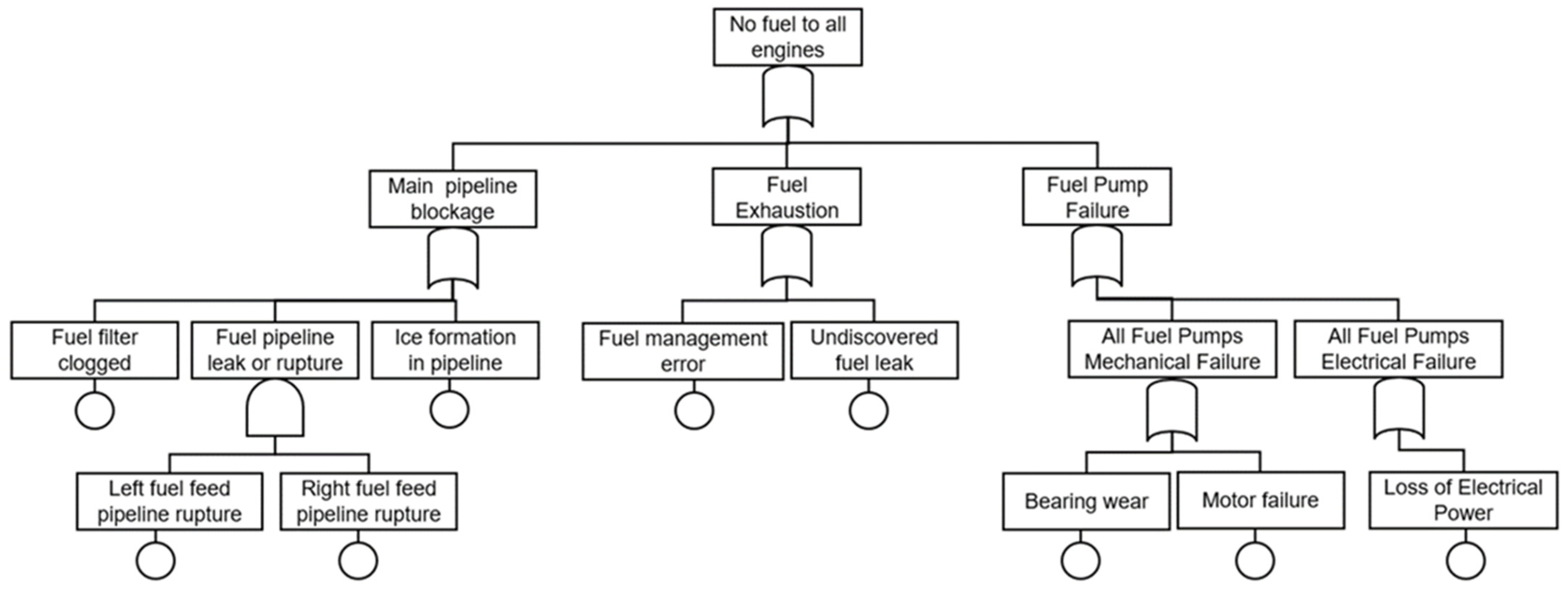
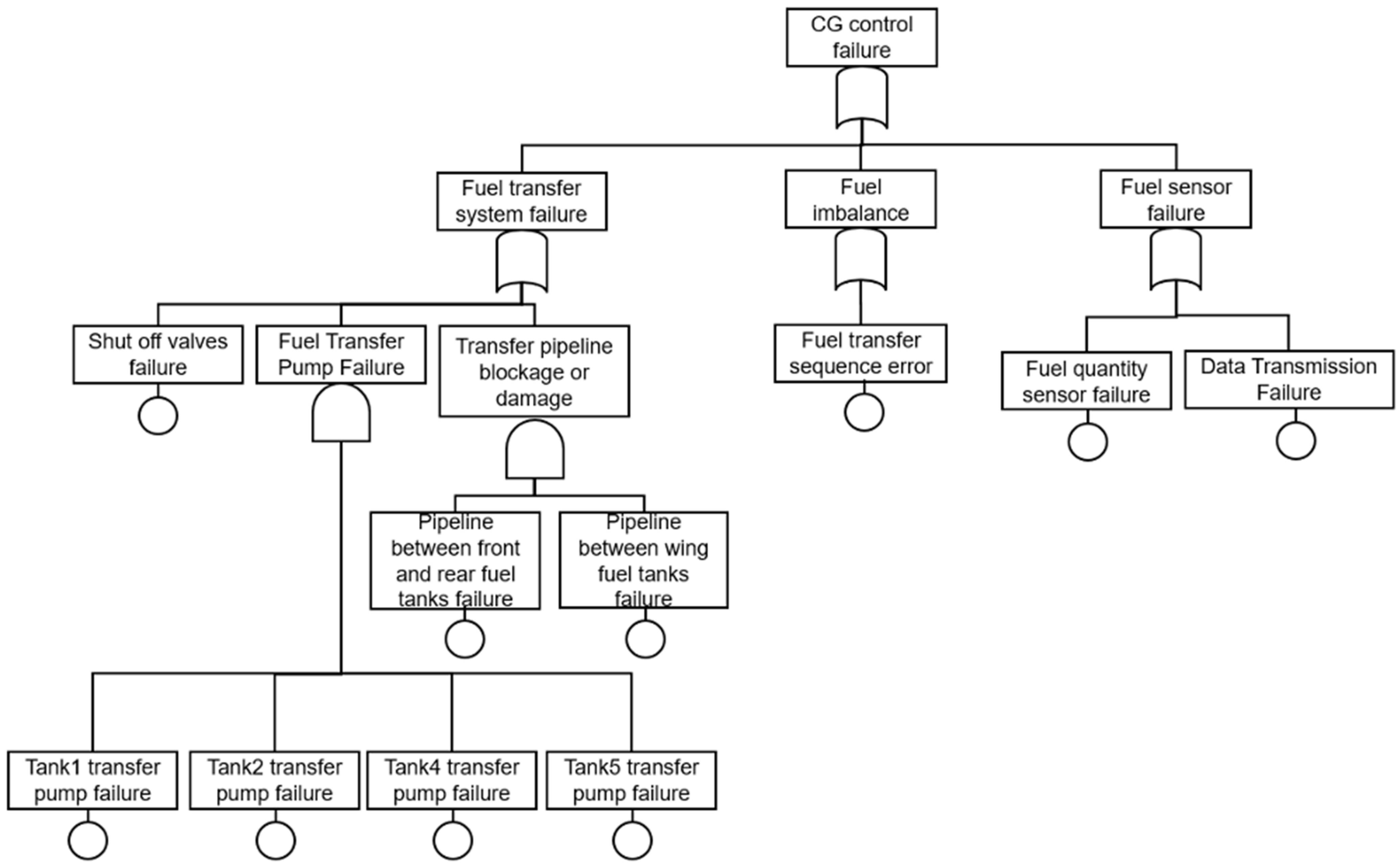
Tools, such as the FHA and FTA, were employed to simulate failure scenarios and assess cascading risks. This systematic approach ensured that potential hazards were identified and quantified in terms of their impact and likelihood.
Detailed fault tree analysis, failure modes and effects analysis, and functional hazard analysis models are provided in
Appendix E,
Appendix F and
Appendix G.
3.4.1. System Architecture Modeling
The system architecture of the conceptual aircraft fuel system was represented using a system modeling language (SysML) within the MBSE environment. SysML models were used to describe the subsystem structure, functional behavior, and interfaces between the system components.
The architecture model captures the relationships between the major fuel system components, including fuel tanks, pumps, fuel transfer lines, and engine feed systems. Functional interactions between these components were represented through SysML block definition diagrams and internal block diagrams, enabling the analysis of the system behavior under various operational conditions.
These architectural models provide a structured representation of subsystem interactions that support the application of safety analysis techniques such as the FHA, FMEA, and FTA.
3.4.2. Hazard Modeling Integration
MBSE architecture models were used to support hazard identification activities by enabling the analysis of functional system behavior alongside subsystem interaction relationships. Hazard analysis techniques were applied within the MBSE framework to identify the potential failure propagation pathways and subsystem dependencies.
By linking functional system architecture models with the spatial subsystem configuration developed in a CAD environment, the modeling framework allows hazard interactions caused by subsystem placement or structural integration to be identified earlier in the design process.
This integrated modeling approach supports more comprehensive hazard identification than conventional document-based safety assessment workflows.
3.4.3. Conceptual Digital Twin Framework
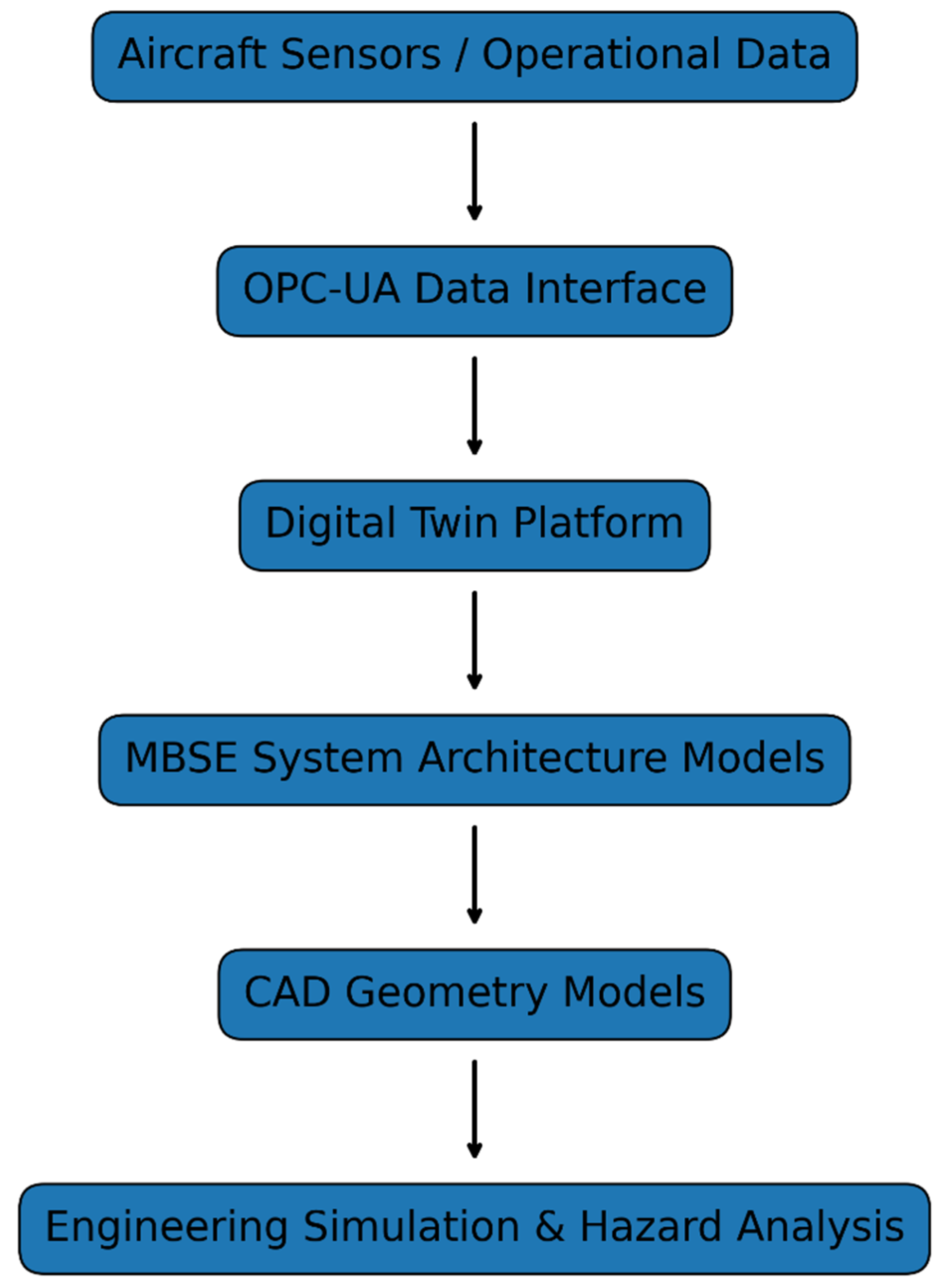
Digital twin concepts are increasingly being applied in aerospace digital engineering environments to represent the structure and behavior of complex engineering systems. A digital twin can be generally defined as a virtual representation of a physical system that integrates system models, simulation capabilities, and, in advanced implementations, operational data to support engineering analysis and lifecycle management.
The maturity of digital twin implementations is commonly classified using reference frameworks, such as the DIN 91345 digital twin model, which describes progressive levels of digital system representation, ranging from static geometry models to fully integrated cyber-physical systems that interact with operational data streams.
The modeling framework developed in this study integrates CAD geometry models with the MBSE system architecture models to represent both spatial subsystem configuration and functional system interactions within a conceptual aircraft design environment. This integration enables simulation-supported hazard identification during early design stages, allowing potential subsystem interaction risks to be evaluated before a detailed aircraft design is completed.
Although the proposed modeling framework incorporates physics-based modeling assumptions, including thermal load estimation and subsystem interaction analysis, it does not incorporate real-time operational data from physical aircraft platforms. Consequently, the modeling environment should be interpreted as a conceptual digital twin framework rather than as a fully operational digital twin implementation.
Within the context of the DIN 91345 maturity classification, the modeling approach developed in this study demonstrated characteristics associated with intermediate digital twin maturity levels, where system architecture models and simulation capabilities were integrated to support the engineering analysis. However, the absence of operational sensor data and real-time system monitoring limits the framework to conceptual digital twin capabilities.
Future research can extend the proposed framework by integrating operational aircraft data streams, real-time system monitoring, and closed-loop simulations between physical aircraft systems and their digital representations. Such an integration would enable the development of fully operational digital twin environments capable of supporting predictive maintenance and real-time safety analyses of aircraft systems. The classification of digital twin maturity levels and their relevance to the present study are summarized in
Table 3.
3.5. Integration of CAD and MBSE
The integration of CAD models with MBSE architectures enables a unified representation of the spatial subsystem configuration and functional system behavior during early aircraft design stages. Conventional aircraft safety analysis methods typically rely on separate documentation-based workflows, where system architecture models and geometric subsystem layouts are analyzed independently. This separation can delay the identification of spatial hazard interactions between aircraft subsystems.
In this study, CAD geometry models and MBSE system architecture models were integrated to support early-stage hazard identification for the conceptual SA-24 Phoenix supersonic aircraft fuel system. The combined modeling environment enables engineers to analyze potential hazard interactions between subsystem components by linking spatial system configurations with functional behavior models.
The integration framework supports iterative interactions between geometric subsystem models and system architecture representations, allowing hazard identification activities to be performed during the conceptual design rather than after a detailed subsystem definition.
3.5.1. Hazard Analysis Integration Workflow
The hazard analysis workflow developed in this study integrates spatial subsystem modeling with functional system architecture analysis. The workflow begins with the development of a conceptual subsystem geometry within the CATIA modeling environment. These geometric models represent the spatial configurations of the fuel tanks, associated structural components, and nearby aircraft subsystems.
Once the subsystem geometry has been established, system architecture models are developed within the MBSE environment using SysML. These models represent the functional relationships between aircraft subsystems and enable the identification of potential failure propagation paths.
The integration of these modeling environments enables the application of hazard analysis methods, such as FHA, FMEA, and FTA, in conjunction with spatial subsystem configuration models.
Using this approach, potential hazard interactions caused by subsystem proximity, thermal effects, or structural integration can be identified earlier in the aircraft design process.
3.5.2. CAD–MBSE Hazard Feedback Loop
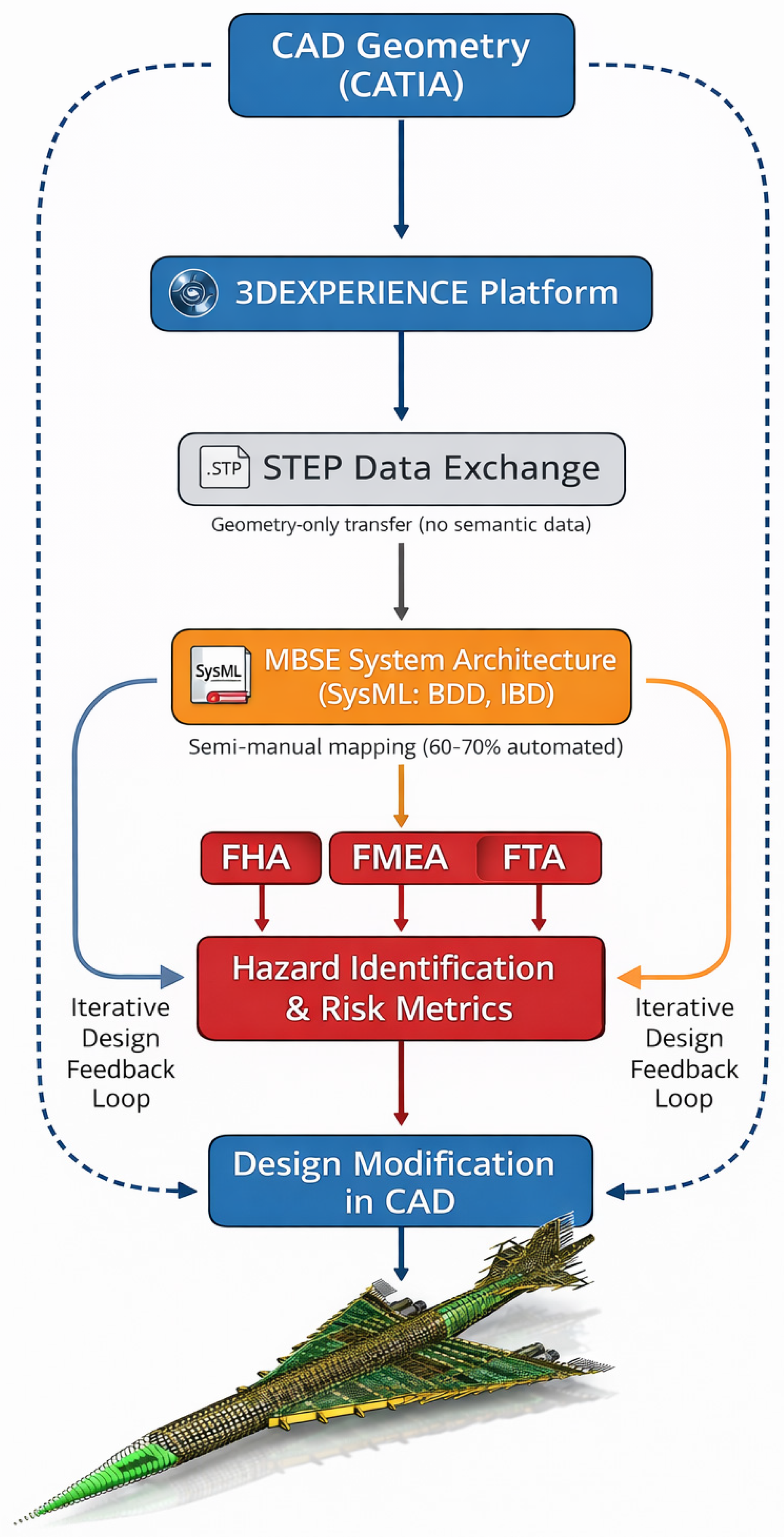
The integration between CAD and MBSE models was implemented through an iterative hazard analysis feedback loop. The CAD geometry models developed in CATIA provided spatial subsystem configurations, including the locations of the fuel tanks, pipelines, and surrounding aircraft systems. These spatial relationships were analyzed to identify potential hazard interactions, such as thermal exposure zones, pipeline proximity to high-temperature components, and fuel system pressurization risks.
When a potential hazard interaction was identified within the CAD environment, the corresponding subsystem relationships were mapped onto the MBSE system architecture model using SysML representations. Hazard events and mitigation strategies were incorporated into the MBSE model through FHA, FMEA, and FTA structures.
The resulting safety analysis outputs informed design modifications within the CAD model, such as the addition of redundant venting pathways, thermal insulation materials, or revised subsystem routing. This iterative feedback process ensured that the spatial subsystem configuration and FHA remained synchronized throughout the conceptual aircraft design phase.
Although the geometric data were exported from CATIA using the Standard for the Exchange of Product Data (STEP) format, full automation between the CAD and MBSE environments was not implemented. Consequently, data transfer and model synchronization required partial manual coordination between the CAD geometry models and MBSE system architecture representations.
While the STEP format preserves geometric fidelity, it does not inherently retain higher-level semantic information such as functional intent, system relationships, or hazard attributes associated with the subsystem components. As a result, traceability between the CAD geometry and SysML-based MBSE models was maintained through structured manual mapping, supported by consistent naming conventions and subsystem identification schemes within the modeling environment.
This semi-manual integration approach introduces potential limitations in maintaining strict traceability during iterative design updates, as well as a risk of semantic data loss when transferring information between modeling domains. In particular, changes in subsystem geometry require corresponding updates in the MBSE hazard models, which may not be automatically synchronized.
Despite these limitations, the workflow enables effective integration of spatial and functional system representations during conceptual design. However, these findings highlight the need for future development of automated CAD–MBSE interoperability solutions to improve data consistency, scalability, and traceability in more complex aircraft system architectures.
The resulting CAD–MBSE workflow forms a closed-loop hazard analysis process in which spatial design information informs the system safety analysis, and the safety analysis results guide subsequent design refinements.
The current CAD–MBSE integration workflow can be considered semi-automated. Core modeling activities, including CAD-based geometry development and MBSE-based system architecture modeling, are performed within their respective software environments. However, the data exchange and mapping between these domains require manual coordination, particularly in the transfer of geometric information and hazard model integration.
Overall, approximately 60–70% of the workflow can be considered automated, while the remaining steps involve manual synchronization and validation. Although this level of integration is sufficient for conceptual subsystem-level analysis, scaling the framework to full aircraft system complexity would require enhanced automation, standardized interoperability protocols, and tighter integration between CAD and MBSE platforms.
3.5.3. CAD–MBSE Data Exchange and Interoperability
The effective integration between CAD models and MBSE architectures requires reliable data exchange mechanisms that allow spatial system models to interact with functional system representations. In the modeling workflow developed in this study, geometric models of the SA-24 Phoenix fuel tank system were generated using the CATIA environment within the 3DEXPERIENCE digital engineering platform.
The geometric data representing the subsystem placement and structural configuration were exported using the STEP (Standard for the Exchange of Product Data) format [
30], which enabled interoperability between CAD environments and external modeling tools. These geometric representations were then referenced during the MBSE architecture modeling process to support hazard interaction analysis between subsystem components.
The data exchange approach adopted in this study aligns with established digital engineering standards. The use of the Standard for the Exchange of Product Data (STEP, ISO 10303) [
30] enables interoperable transfer of geometric information between CAD environments. System architecture modelling within the MBSE environment is based on the Systems Modeling Language (SysML), defined by the Object Management Group (OMG) standard [
31]. While these standards support interoperability at geometric and architectural levels, limitations remain in the transfer of higher-level semantic information, highlighting the need for more integrated model-based data exchange frameworks in future digital engineering environments. Emerging Model-Based Data Exchange (MBDE) approaches aim to address these limitations by enabling tighter integration between system architecture and geometric models. In particular, next-generation standards such as SysML v2 [
31] are being developed to enhance model interoperability and traceability across engineering domains.
In addition, co-simulation frameworks such as the Functional Mock-up Interface (FMI) provide a potential pathway for integrating multidisciplinary system models within a unified simulation environment. Although such approaches were not implemented in the present study, they represent important directions for future development of fully integrated CAD–MBSE digital engineering frameworks. The data exchange workflow and associated modeling environments used in the CAD–MBSE integration process are summarized in
Table 4.
Although this approach enables the effective integration of spatial and functional system models during conceptual aircraft design, several interoperability challenges remain. The transfer of geometric data through standardized exchange formats may result in minor losses in geometric fidelity, particularly when complex parametric model features are simplified during export. Additionally, maintaining synchronization between CAD geometry updates and MBSE architecture models may require manual coordination within current modeling environments.
Figure 1 illustrates the data flow between the spatial subsystem geometry and functional system architecture models used in the hazard analysis process.
Although the use of standardized exchange formats enables interoperability among modeling environments, several limitations remain. Exporting complex parametric geometries through STEP files may result in the partial simplification of geometric features, which can reduce the geometric fidelity when compared with the native CAD model. In addition, maintaining synchronization between CAD model updates and MBSE architecture models may require manual coordination in the current modeling environments.
Despite these limitations, the integration workflow provides an effective approach for combining spatial subsystem configurations with functional system architecture modeling during early hazard identification activities.
3.5.4. Convergence Criteria for Iterative CAD–MBSE Design
The integration of CAD models with the MBSE architecture enables an iterative design workflow in which the subsystem geometry and system behavior models are progressively refined during the conceptual aircraft design.
From a systems modelling perspective, the iterative CAD–MBSE coupling process can be interpreted as a fixed-point convergence problem, where successive updates to subsystem geometry and system behavior models lead to progressively smaller changes in system response. Convergence is achieved when the variation in hazard risk metrics between iterations falls below a predefined threshold, indicating that the coupled spatial–functional system representation has reached a stable solution. This behavior is consistent with iterative convergence principles commonly applied in multidisciplinary design optimization and coupled system simulations.
To formalize this convergence behavior, the variation in hazard risk metrics between successive iterations can be expressed as:
where
Rn represents the hazard risk metric (e.g., Risk Priority Number) at iteration
n, and ε denotes a prescribed convergence tolerance. In this study, a threshold value of ε = 0.05 (5%) is adopted to define convergence.
The iterative coupling between subsystem geometry and hazard evaluation can be conceptually represented as:
where
Pn represents CAD-derived spatial parameters,
H(·) denotes the hazard evaluation function, and
D{n+1} corresponds to the updated subsystem design configuration. Equations (4) and (5) provide a simplified mathematical representation of the iterative CAD–MBSE coupling process used during conceptual hazard analysis.
This formulation provides a simplified representation of the coupled CAD–MBSE interaction for early-stage hazard analysis, rather than a fully implemented co-simulation framework.
During each modeling iteration, updates to the subsystem spatial configuration within the CAD environment were evaluated using hazard analysis techniques implemented within the MBSE architecture model. This helped assess the potential subsystem interaction hazards and identify safety-critical design conditions.
To ensure the stability of the modeling process, convergence criteria were defined to determine when the iterative design loop stabilized. The design iteration process was considered to converge when the calculated system risk metrics exhibited less than five percent variation across three consecutive design iterations and when the thermal safety margin associated with fuel tank operating temperatures remained stable within the analyzed flight conditions. The convergence criteria used to evaluate the stability of the iterative CAD–MBSE design process are summarized in
Table 5.
These convergence criteria ensure that the integrated modeling environment produces consistent hazard analysis outcomes and provides a stable basis for evaluating subsystem safety interactions during the conceptual aircraft design phase.
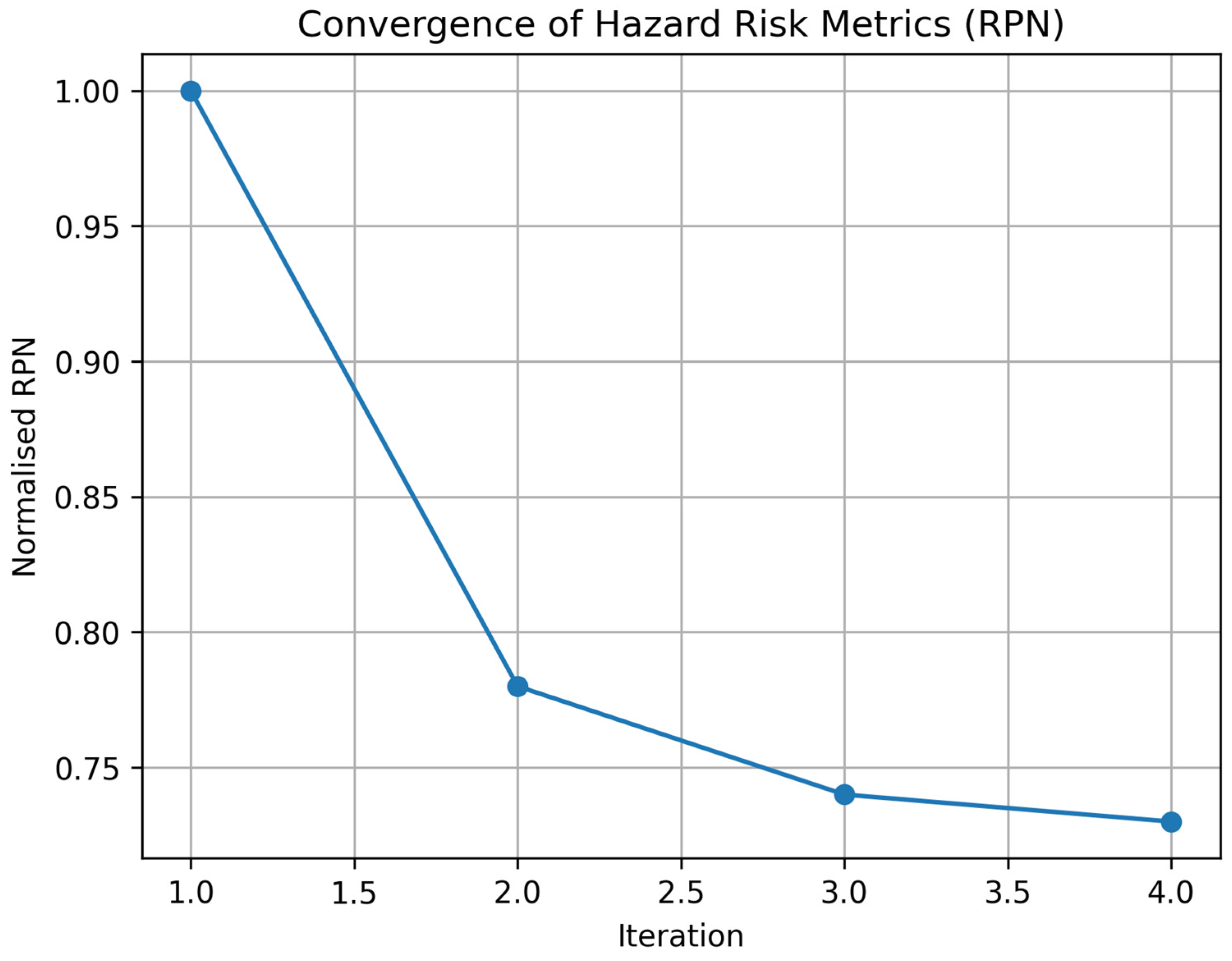
Figure 2 illustrates the convergence behavior of representative hazard risk metrics across successive design iterations, demonstrating stabilization consistent with the defined convergence criterion and supporting the fixed-point interpretation of the iterative CAD–MBSE coupling process.
3.6. Zonal Safety Analysis (ZSA)
The ZSA was conducted using the integrated CAD–MBSE framework to systematically identify and mitigate hazards within the fuel tank zone. This analysis begins with the identification of potential risks such as fuel leakage, thermally induced vaporization, and over-pressurization. These risks were categorized by likelihood and severity, enabling prioritization in the mitigation process.
Tools, such as the FHA and FTA, were used to analyze the propagation of failure scenarios and their potential impact on the overall system. For instance, a fault tree may map the consequences of a venting system failure, illustrating how it could lead to fuel vapor ignition. Mitigation strategies, such as the introduction of redundant safety mechanisms or improved material selection, have been proposed and validated through simulations. This proactive approach ensures that hazards are not only addressed, but also prevented from escalating into critical failures.
3.7. Validation and Benchmarking
The final phase involved validating the integrated framework and benchmarking its performance against conventional methodologies. The proposed CAD–MBSE hazard analysis framework was validated using three complementary approaches. First, FHA, FMEA, and FTA were applied within the integrated modeling environment to evaluate the ability of the framework to identify subsystem interaction hazards during conceptual aircraft design. Second, comparative benchmarking was performed using published fuel system characteristics from historical and contemporary supersonic aircraft, including the Concorde, as well as from conceptual next-generation supersonic transport designs. Third, a sensitivity analysis of the key failure probability parameters was conducted to assess the robustness of the predicted hazard risk reduction metrics. These validation procedures helped collectively assess the capability of the proposed framework in supporting early-stage hazard identification and design mitigation during conceptual aircraft development. Case studies were conducted using the SA-24 Phoenix fuel-tank system to evaluate the effectiveness of the framework for hazard identification and mitigation. Comparative analyses using historical data highlight the advancements made through the integration of CAD and MBSE.
Metrics, such as the design efficiency, safety compliance, and risk reduction, helped quantify the impact of the framework. This validation phase ensured that the methodology is not only effective but also practical for applications in the aerospace industry.
This methodology integrated the CAD and MBSE into a unified framework for ZSA, thereby helping address the complexities of supersonic aircraft design. By combining spatial precision with functional analysis, this approach enables early hazard identification, optimizes design processes, and ensures compliance with industry regulations. As demonstrated in its application to SA-24 Phoenix, the framework provides a conceptual methodology for integrating spatial subsystem modeling with system architecture hazard analysis during early aircraft design.
4. Case Study: SA-24 Phoenix-Supersonic Aircraft
The SA-24 Phoenix, a conceptual supersonic transport aircraft, represents the forefront of innovation in aerospace engineering. This case study highlights the application of ZSA to the design and development of its fuel tank system, which is a critical subsystem essential for operational safety and efficiency. This methodology integrates CAD and MBSE to proactively identify and mitigate risks during the early design phases.
The SA-24 Phoenix operates at supersonic speeds and high altitudes, with its systems subjected to extreme conditions, such as significant thermal loads, dynamic pressures, and high aerodynamic forces. These conditions necessitate a robust fuel tank system that not only ensures operational efficiency but also adheres to stringent safety standards, such as EASA CS-25 [
29]. The ZSA framework employed in this study focuses on addressing these challenges using a systematically integrated approach that enhances hazard detection and mitigation.
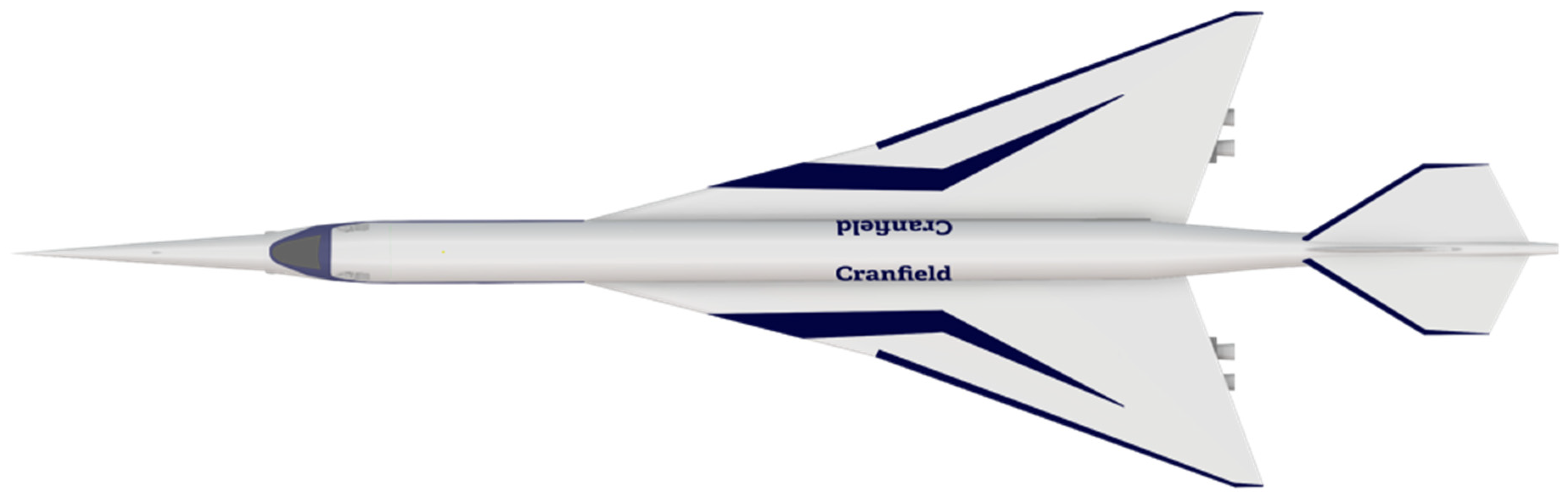
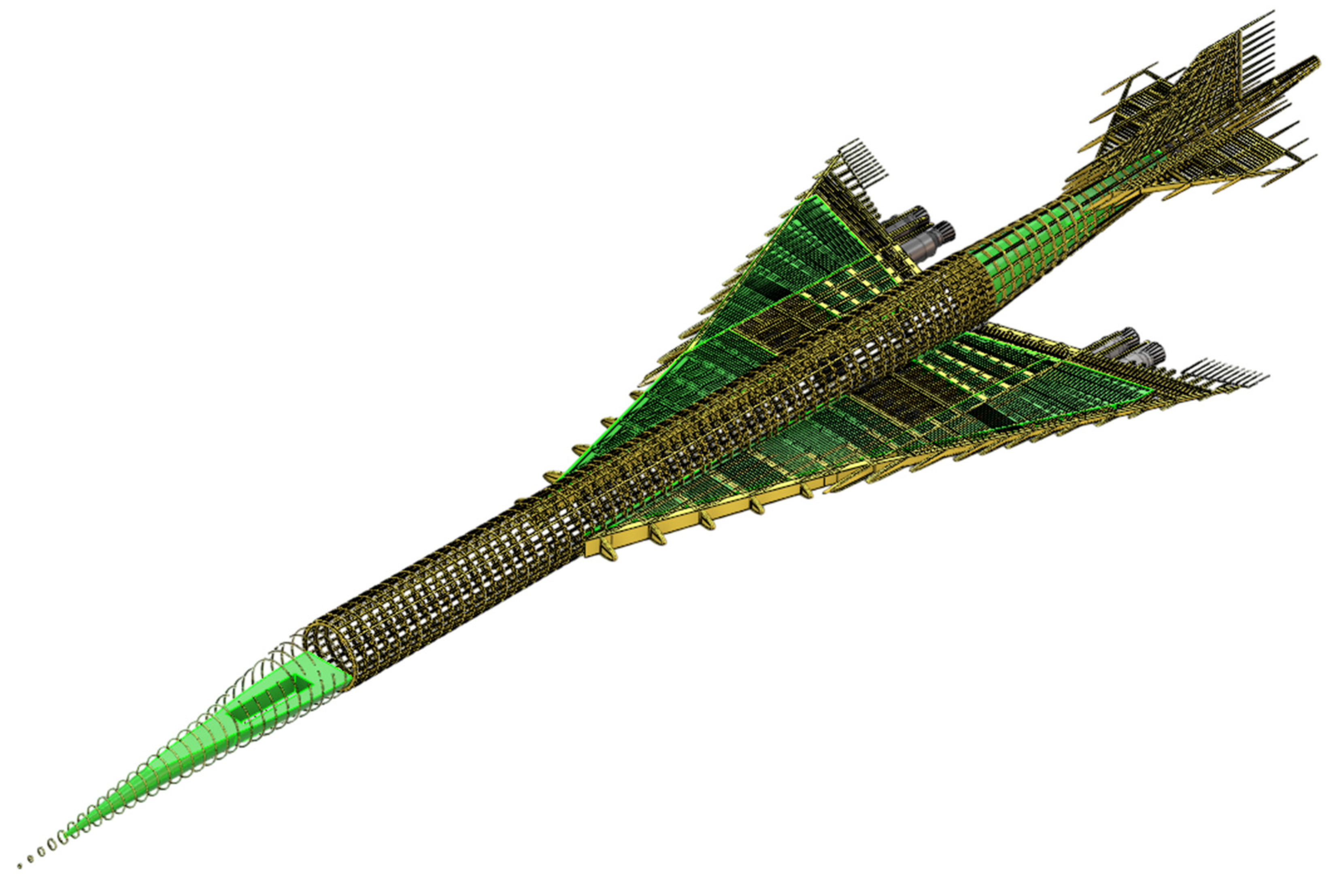
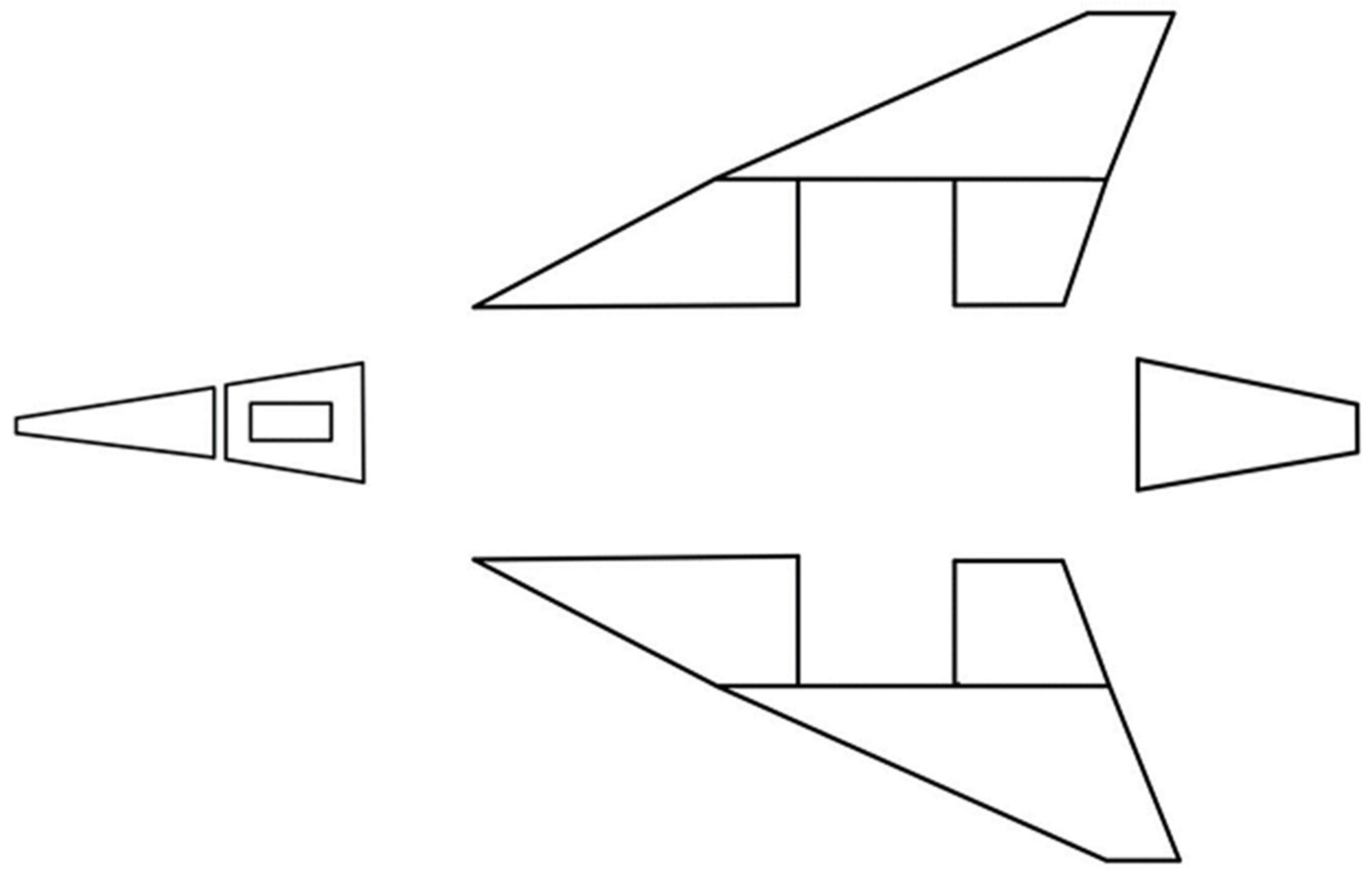
Figure 3 presents the top view of the SA-24 Phoenix aircraft, illustrating the overall configuration and spatial layout, while
Figure 4 shows the side view, highlighting the aircraft geometry and subsystem integration. The SA-24 Phoenix supersonic aircraft serves as the reference platform for this study, building upon prior technical development work conducted at Cranfield University [
32].
4.1. Overview of the SA-24 Aircraft Fuel Tank System
The fuel tank system of the SA-24 Phoenix is a highly integrated subsystem designed to satisfy the demands of supersonic travel. Its architecture focuses on optimizing weight distribution, ensuring fuel efficiency, and maintaining stringent safety standards under challenging conditions.
The storage configuration incorporates integral tanks located in the wings and a fuselage strategically placed to maintain an optimal center of gravity (CG) throughout all the flight phases. The use of advanced materials, including titanium alloys and carbon composites, ensures that tanks can withstand rapid pressure and temperature fluctuations during supersonic operations. This combination of material innovation and structural optimization minimizes the risk of fuel system failure, while reducing the overall weight.
Subsystems integrated within the fuel tank system include:
- (1)
Fuel transfer system: The dual-pump configuration provides redundancy to ensure continuous fuel flow to the engines, even in the event of a single-component failure. Cross-feed valves allow fuel redistribution between tanks to maintain the CG and support emergency operations.
- (2)
Venting system: Multiple venting pathways prevent over-pressurization resulting from thermal expansion. The flame arrestors integrated into the venting design minimize the risk of ignition from external sparks or high temperatures.
- (3)
Fuel quantity indication system (FQIS): Capacitance-based sensors monitor fuel levels with high precision and relay the data to cockpit displays. This real-time feedback enhances the situational awareness of the pilots, particularly during long-range supersonic flights.
Safety features, such as redundant mechanisms and advanced insulation, significantly enhance system resilience. Insulation materials, validated through thermal simulations, mitigate the risk of fuel vaporization caused by aerodynamic heating. These elements collectively ensure that the fuel system meets both operational and safety benchmarks.
4.1.1. Tank Configuration and Layout
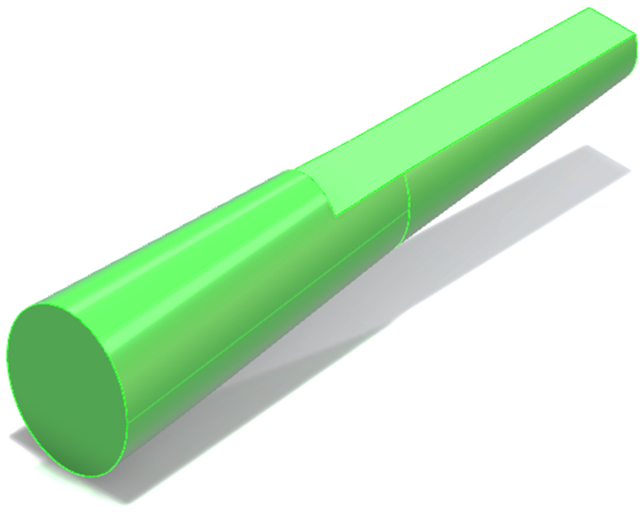
Figure 5 shows a top–down view of the fuel tank placement and storage configuration of the SA-24 Phoenix aircraft. This configuration ensures an efficient weight distribution and optimizes its aerodynamic performance.
Forward tank: Located in the nose section, the forward tank helps balance the aircraft during takeoff and landing. It is critical to maintain the CG under various fuel load scenarios. The forward tank is smaller than the wing tanks and is primarily used for trim adjustments.
Wing tanks: Wing tanks serve as primary storage units and are located within the structural wing cavities. Their placement near engines minimizes the length of fuel pipelines, reduces weight, and increases efficiency. The tanks were divided into sections with internal baffles to prevent fuel sloshing during dynamic flight conditions.
Aft tanks: Positioned at the rear fuselage, the aft tank plays a critical role in CG management during supersonic cruises. The fuel from this tank is first consumed to shift the CG forward, thereby reducing the aerodynamic drag.
Tank insulation: All the tanks were insulated with advanced materials to protect against the heat generated during supersonic flight. This insulation reduces the risk of vaporization and ensures fuel stability.
Design considerations: The arrangement of tanks prioritizes operational efficiency by reducing the impact of fuel weight on aerodynamic performance. The modular design of tanks simplifies maintenance and facilitates inspection of structural integrity.
Additional geometric configurations and detailed CAD representations of the fuel tank system are provided in
Appendix C.
4.1.2. Fuel Transfer and Shut-Off Valve System Layout
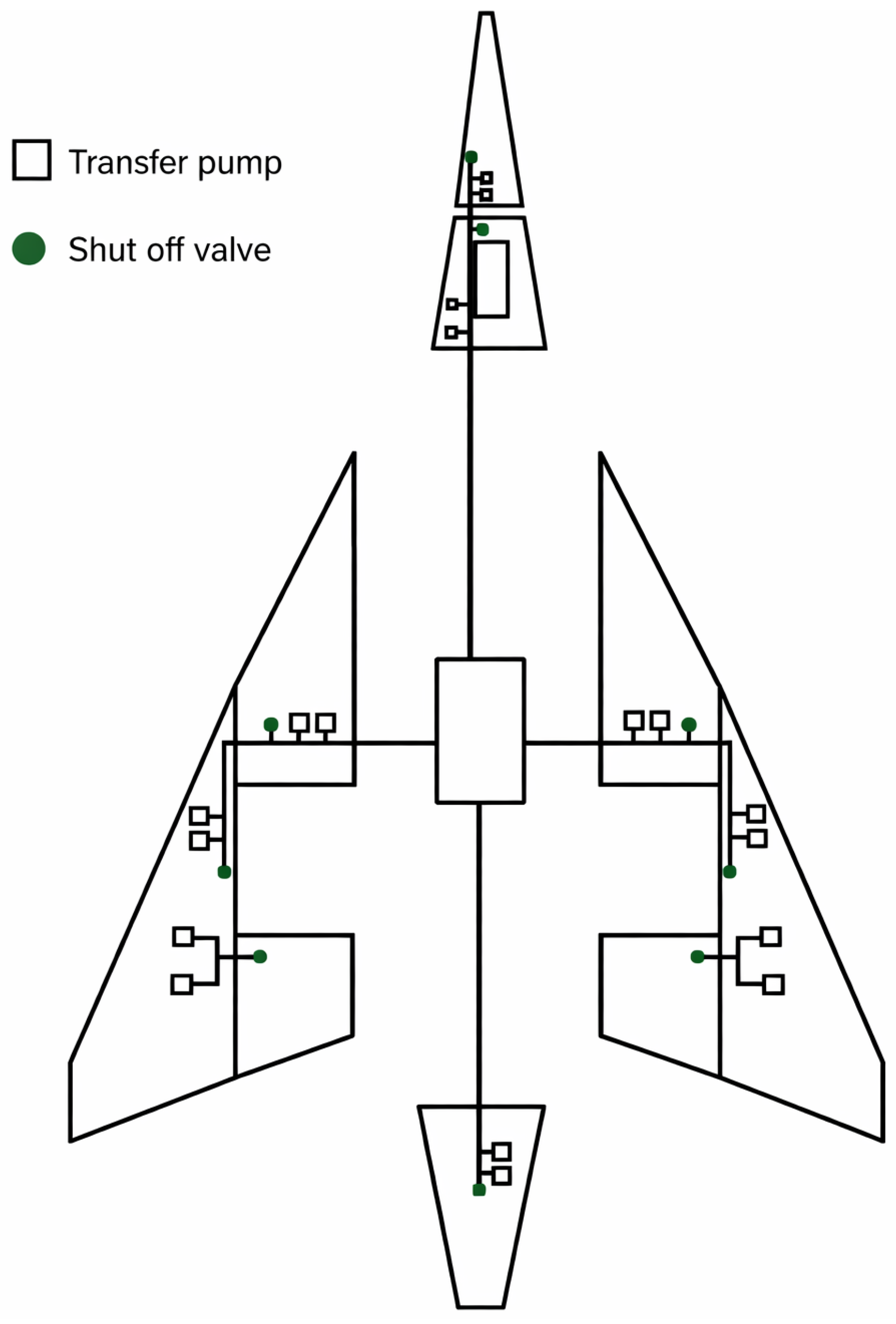
Figure 6 illustrates the layout and key components of the SA-24 Phoenix fuel tank system, focusing on the transfer pumps and shut-off valves. Each component is strategically positioned to ensure safety, efficiency, and reliability under supersonic flight conditions.
Transfer pumps (outlined boxes): Transfer pumps are located within the fuel tanks in the wings, forward fuselages, and aft fuselages. These pumps ensure consistent fuel delivery to the engines and manage fuel redistribution between tanks to maintain the CG of the aircraft. Redundant pumps are placed in high-demand zones, such as the main wing tanks, to provide backup in the event of a single pump failure. This redundancy aligns with EASA CS-25 requirements for system reliability.
Shut-off valves (green circles): Shut-off valves are located at critical junctions in the fuel pipeline system. These valves are designed to isolate sections of the system in the event of fuel leaks or emergencies such as engine failure. The placement of shut-off valves ensures that fuel flow can be immediately halted in specific zones, thereby preventing hazardous scenarios such as over-pressurization or fuel pooling in damaged areas.
Flow path: The centralized pipeline connects all tanks to the engines, with the main control located in the mid-fuselage section. This layout ensures efficient fuel transfer and easy maintenance.
Functionality highlights: The system balances fuel distribution between the forward, wing, and aft tanks while maintaining CG stability. Shut-off valves provide additional safety by enabling rapid isolation of damaged or malfunctioning components.
When combined, these diagrams represent a comprehensive view of the SA-24 Phoenix fuel system, showing both the functional components (transfer pumps and valves) and spatial configuration (tank placement). Together, they demonstrate how a fuel system can be engineered for safety, redundancy, and performance in a high-stress supersonic flight environment.
4.2. Identification of Zonal Systems
The CAD model of the SA-24 aircraft (
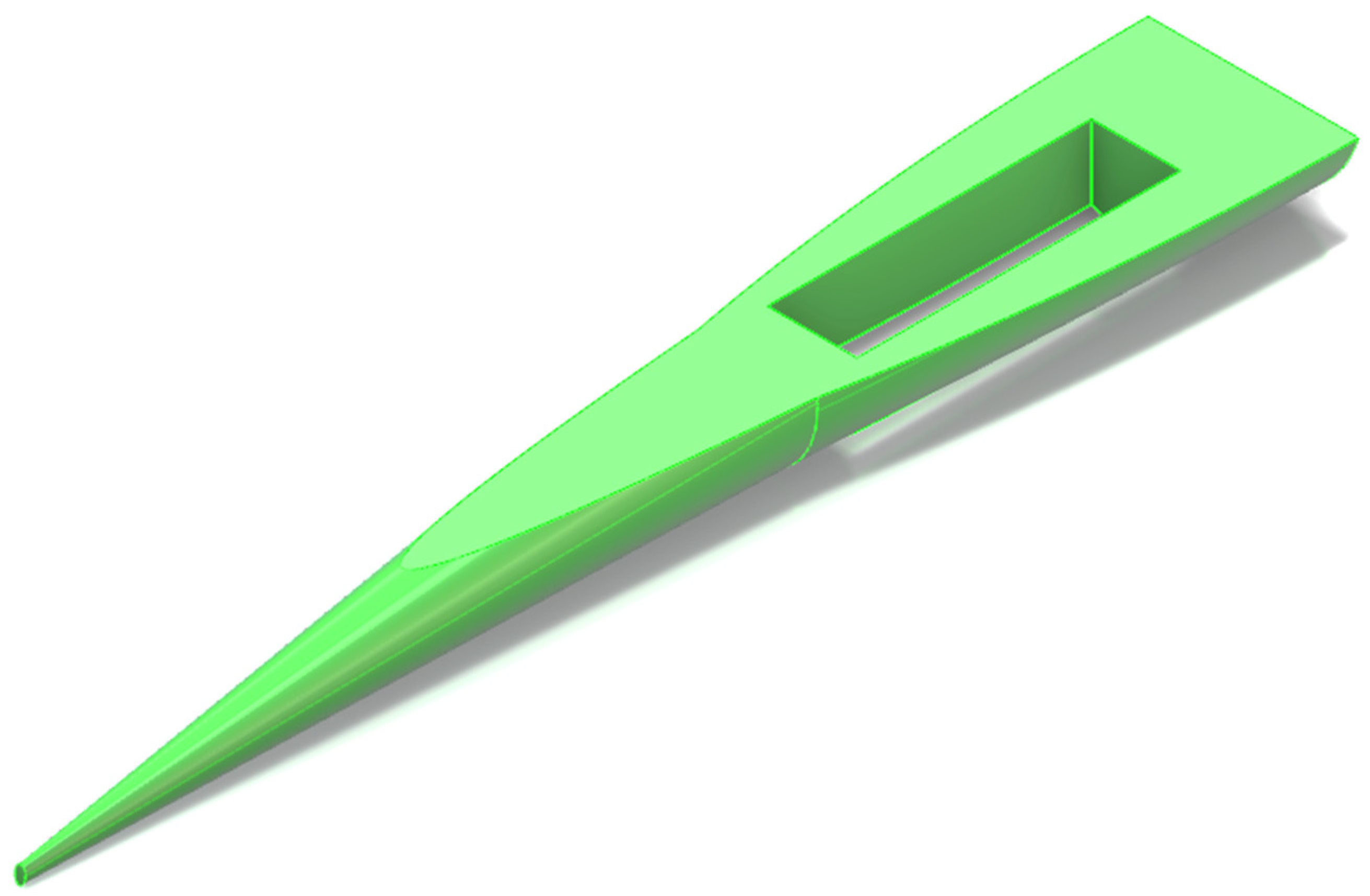
Figure 7) shows the structural design and integration of its fuel tank system, with green areas representing the fuel tanks. These images provide insights into the layout, distribution, and engineering considerations of the fuel systems within the aircraft. This design prioritizes efficient weight distribution, structural integrity, and operational safety to meet the challenges of supersonic flight.
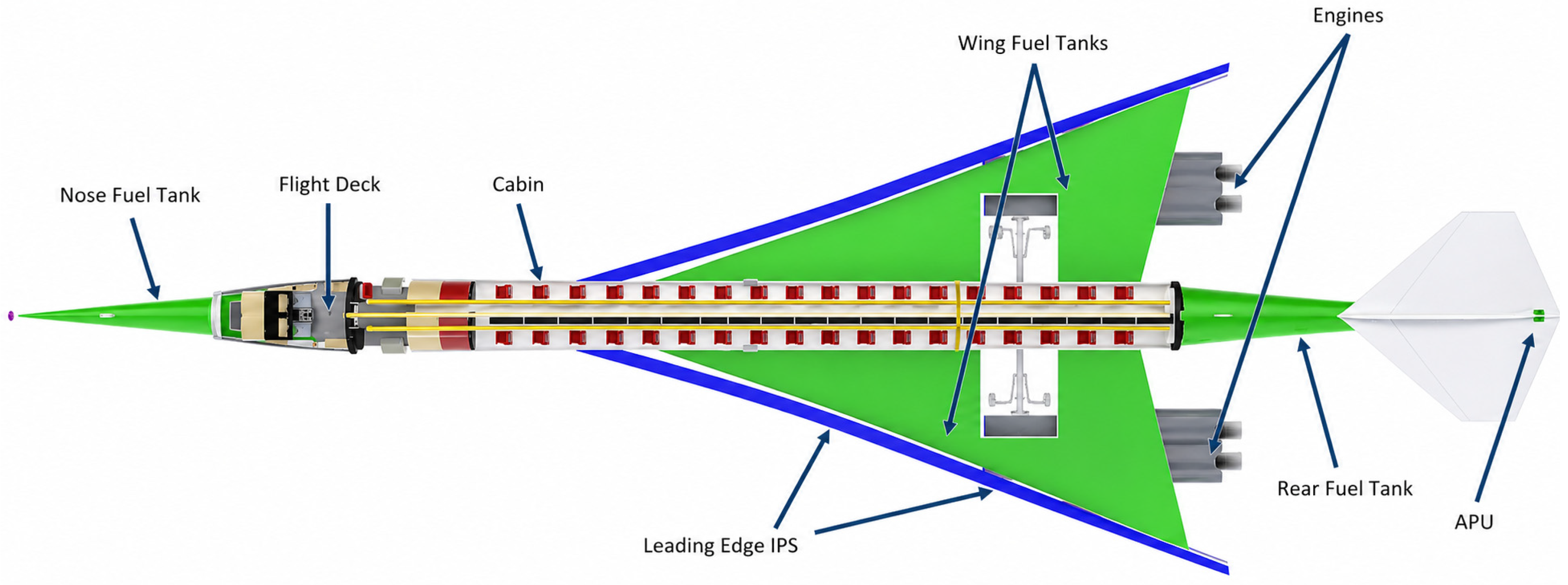
CAD models serve as baselines for integrating MBSE workflows, enabling early hazard detection and mitigation during the design phase. By mapping the fuel tank system layout, these models provide a clear understanding of spatial configurations, subsystem interactions, and potential zonal hazards. The system-level layout of the SA-24 Phoenix aircraft, including subsystem distribution and key interaction zones relevant to zonal hazard analysis, is illustrated in
Figure 8.
Zonal safety analysis (ZSA): This view allows for identifying zones where multiple systems intersect, such as fuel pipelines near engine components, which pose potential ignition risks.
CAD and MBSE integration: The model can be linked to MBSE tools to simulate hazard scenarios such as over-pressurization or thermal stress in specific zones.
Centre of gravity (CG) management: The even distribution supports CG stability and reduces the risk of imbalance during flight.
Hazard identification: MBSE tools can overlay failure scenarios, such as leakage, from wing tanks, affecting aerodynamic performance or triggering cascading failures in adjacent systems.
Thermal management: This helps assess zones exposed to aerodynamic heating, such as forward and rear tanks, and highlights the insulation requirements.
Pressure regulation: CAD simulations can be used to validate venting system designs to mitigate over-pressurization risks.
Structural safety analysis: MBSE model can simulate the effects of dynamic loads and material fatigue on tank compartments, ensuring structural integrity under supersonic conditions.
Subsystem integration: The model demonstrates how fuel tanks are integrated with other systems, such as environmental control and propulsion, enabling a cross-domain hazard analysis.
Dynamic simulations: MBSE model can assess how fuel transfer from the tail tank impacts CG stability during different flight phases.
ZSA insights: The proximity of the tail tank to engine exhaust zones introduces fire hazards that can be mitigated by enhanced insulation and flame arrestors. The system-level layout of the SA-24 Phoenix aircraft, including subsystem distribution and key interaction zones relevant to zonal hazard analysis, is illustrated in
Figure 9.
Proactive hazard detection: The CAD models provide a detailed spatial framework that can be analyzed using ZSA methodologies. Potential hazards, such as fuel leakage, ignition risks, and over-pressurization, can be identified and addressed early in the design process.
MBSE integration: Linking the CAD models to MBSE workflows enables dynamic simulations of subsystem interactions. For example, fuel transfer simulations can validate the effectiveness of pumps and valves, whereas the FTA can identify cascading risks.
Regulatory compliance: The visualization of fuel tank placement and integration supports compliance with EASA CS-25 standards, particularly in areas such as venting system design, fire protection, and structural integrity.
Iterative design optimization: CAD models allow iterative refinements based on simulation results. For example, repositioning the venting pathways or enhancing the tank insulation can be directly implemented in a CAD environment.
Cross-System Interface Zonal Safety Analysis
An aircraft fuel system interacts with multiple adjacent subsystems, including propulsion components and ECS elements. These interactions can introduce potentially hazardous conditions related to thermal exposure, fire propagation, and subsystem proximity.
To evaluate these interactions, a ZSA interface matrix was developed to identify the potential hazards associated with subsystem integration within aircraft structures. The matrix considers the spatial relationships between the fuel system components and neighboring subsystems, focusing on areas where elevated thermal loads or ignition sources may be present.
The ECS may introduce elevated temperature conditions due to the air conditioning pack operation and bleed air routing. These thermal loads can affect the structural components of the fuel tank and the associated fuel transfer lines if the subsystem separation distances are insufficient.
Similarly, the propulsion system components located within the engine bay represent potential ignition sources in the event of fuel leakage. Therefore, fire propagation risks associated with fuel system components located near propulsion system structures must be considered during early subsystem layout design.
The integration of CAD subsystem geometry with MBSE system architecture models enables the analysis of subsystem interaction hazards during conceptual aircraft design. The cross-system interaction hazards and associated mitigation strategies identified through the zonal safety analysis are summarized in
Table 6.
4.3. Application of the ZSA Framework to the SA-24 Fuel System
Dedicated certification standards for commercial supersonic aircraft are still evolving, including updates such as the EASA CS-25 Amendment 27. This study adopts the safety requirements of the existing CS-25 fuel system as a conceptual regulatory baseline for hazard identification. These requirements were applied in a modified analytical context to account for the thermal and operational characteristics associated with sustained supersonic flight conditions. This approach allows established airworthiness safety principles, such as ignition prevention, fuel system redundancy, and failure containment, to be applied during conceptual aircraft design, while acknowledging that detailed certification criteria for future supersonic transport aircraft may evolve.
The analysis focused on the integration of CAD and MBSE workflows to enhance the precision and efficiency of hazard detection.
4.3.1. Hazard Identification
Key hazards identified through the ZSA include:
Thermal risks: High aerodynamic heating during a supersonic cruise can increase fuel temperatures, leading to vaporization and pressure build-up.
Over-pressurization: Malfunctioning venting systems or blockages can result in excessive internal pressures, risking tank deformation or rupture.
Leakage: Structural fatigue, material degradation, or faulty seals can cause fuel leaks, thereby posing fire hazards.
Ignition Risks: Proximity to electrical systems and engines introduces the potential for vapor ignition.
4.3.2. Mitigation Strategies
To address these hazards, the following strategies were implemented:
Thermal management: Advanced insulation materials and heat shields were applied to minimize heat transfer to the fuel tanks. The simulations helped validate the effectiveness of these materials in maintaining stable fuel temperatures under operational conditions.
Pressure regulation: Dual venting pathways with redundant controls were designed to maintain the pressure equilibrium. Pressure sensors provide real-time feedback, enabling the early detection of anomalies.
Structural reinforcement: Reinforced composite materials and improved sealing techniques have been utilized to enhance the durability of tank compartments and minimize leakage risks.
Proactive monitoring: The FQIS and integrated sensors provide continuous monitoring of fuel levels, pressures, and temperatures, enabling timely corrective actions.
4.3.3. Validation Through CAD and MBSE
The CAD and MBSE tools were instrumental in validating the proposed safety measures:
CAD simulations: Thermal and structural analyses were performed to assess the resilience of the fuel tanks under extreme conditions.
MBSE models: Digital twins simulate failure scenarios and subsystem interactions, enabling the refinement of design elements.
Iterative feedback: Simulation results informed adjustments to the tank design, ensuring alignment with safety standards.
4.3.4. Human–Machine Interface Zonal Safety Analysis
The fuel system monitoring architecture of the aircraft includes several human–machine interface (HMI) components that allow the flight crew to monitor the fuel tank status and system operating conditions. These interfaces provide critical information regarding the fuel quantity, fuel transfer operations, and potential system anomalies.
The FQIS represents the primary interface through which flight crews monitor fuel system status. This system typically integrates fuel tank sensors, signal processing units, and cockpit display interfaces to provide real-time fuel quantity measurements.
Failures within the HMI may lead to incorrect or misleading information being presented to the flight crew. Potential failure conditions include incorrect sensor readings, display interface malfunctions, or delayed system status updates. Such failures can affect pilot decision-making during fuel management operations.
To evaluate these risks, a ZSA of the HMI components was conducted to identify potential failure modes associated with fuel system monitoring displays. The analysis focused on identifying the conditions under which incorrect fuel status information may be presented to flight crews and assessing potential mitigation strategies. The identified failure modes, associated hazards, and mitigation strategies for the fuel system human–machine interface are summarized in
Table 7.
5. Results
This section presents the results obtained by applying the ZSA integrated with CAD and MBSE to the fuel tank system of the SA-24 Phoenix aircraft. The findings were evaluated and analyzed to demonstrate their implications for the overall safety, operational performance, and regulatory compliance of the aircraft. Safety performance improvements were evaluated using FMEA, FHA, and FTA outputs generated during the modeling process.
5.1. Hazard Identification Results
The key hazards identified through the integrated modeling workflow included thermal exposure risks, fuel system pressurization hazards, and potential fuel leakage scenarios associated with subsystem interactions within the aircraft structure.
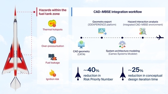
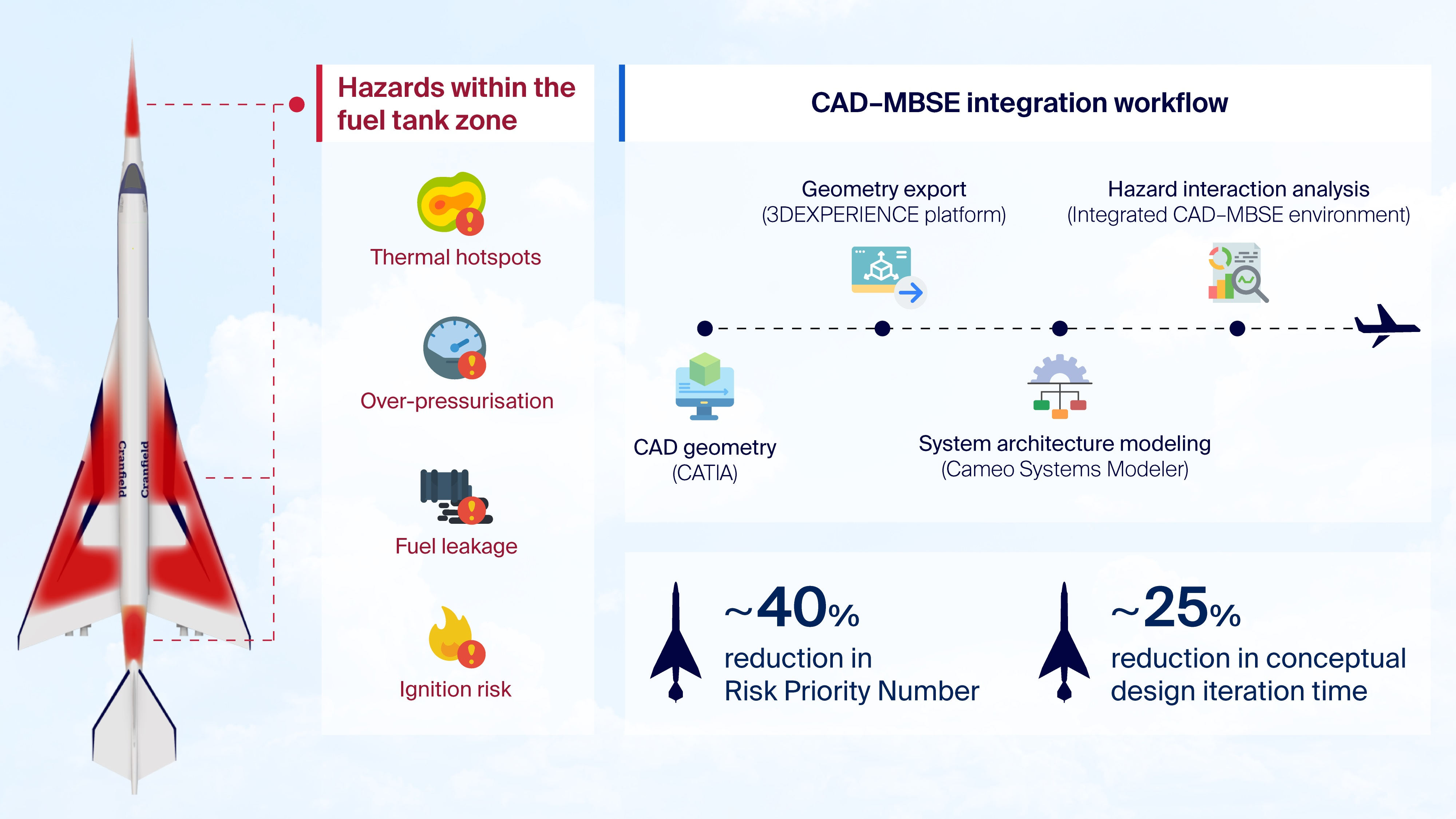
Thermal risk mitigation: The introduction of thermal insulation materials and heat shielding reduced the FMEA risk priority number (RPN) associated with thermally induced fuel vaporization hazards by approximately 40%, based on the hazard scoring results presented in
Table 8. Thermal simulations using CAD indicated that the fuel temperature remained within acceptable conceptual operating limits during the analyzed supersonic cruise conditions.
Pressure regulation efficiency: Dual venting pathways supported by redundant pressure sensors effectively maintained the pressure equilibrium within the fuel tanks. This reduced the over-pressurization risk by 35%, ensuring the structural integrity of the tanks under extreme conditions.
Leakage prevention: Structural reinforcements, enhanced sealing techniques, and real-time monitoring systems reduced the probability of fuel leakage by 50%. This addresses a significant hazard that can lead to fire risks or environmental contamination.
The adoption of CAD and MBSE tools also improved the design and development process by enabling iterative refinement of the subsystem geometry and system behavior models. CAD-based simulations supported the optimization of component placement and thermal insulation design, while MBSE modeling enabled the evaluation of subsystem interactions and failure propagation scenarios. The integrated modeling workflow reduced the conceptual design iteration cycle from approximately twelve weeks to nine weeks, representing a 25% reduction in the design iteration time.
5.2. Quantitative Risk Reduction Analysis
The safety improvement percentages reported herein were derived from the FMEA, as presented in Appendix
Table A5. The RPN for each hazard was calculated as the product of the severity (S), occurrence probability (O), and detection capability (D).
The baseline RPN values represent the risk levels identified using conventional ZSA during the conceptual design. The estimated occurrence and detection ratings were reduced following the implementation of mitigation strategies enabled by the integrated CAD–MBSE framework, such as redundant venting, improved thermal insulation, and enhanced fuel system monitoring.
The RPN represents a qualitative engineering risk prioritization metric rather than a continuous physical measurement scale. To further clarify the interpretation of risk metrics used in this study,
Table 8 presents a comparison of different risk representation approaches.
The classification presented in
Table 8 distinguishes between different levels of risk representation used in engineering safety analysis. In the present study, the Risk Priority Number (RPN) is employed as a semi-quantitative metric to prioritize hazards based on severity, occurrence, and detectability. It is important to note that RPN does not represent an absolute probability of system failure, but rather serves as a relative ranking tool for decision-making during conceptual design. To partially account for uncertainty in input parameters, sensitivity analysis has been conducted (
Section 5.6), providing a first-order assessment of the robustness of hazard rankings under parameter variation. A full probabilistic risk assessment framework is beyond the scope of the present study and is identified as an area for future work.
Consequently, the relative percentage reductions reported herein represent changes in the FMEA risk-ranking scores used to prioritize hazards during conceptual design rather than experimentally measured reductions in the failure probability of the physical system.
As the RPN is derived from discrete severity, occurrence, and detection ratings, variations in these parameters can influence the absolute values of the risk metrics. However, within reasonable bounds of parameter variation, the relative ranking of critical hazards remains stable, ensuring consistency in hazard prioritization.
The sensitivity analysis presented in
Section 5.6 provides further support for this observation, demonstrating that moderate variations (±10%) in failure probability inputs result in proportionally limited changes in overall system risk metrics. This indicates that the hazard identification outcomes are robust to reasonable uncertainty in the input parameters.
The resulting decrease in the RPN values was used to estimate the relative improvement in the system safety performance. The relative reduction in FMEA risk priority number (RPN) values following the implementation of CAD–MBSE mitigation strategies is summarized in
Table 9.
The relative improvement percentages were calculated from the reduction in the RPN values after applying the mitigation strategies identified through the CAD–MBSE hazard analysis process. These reductions reflect the improved detection capability, lower occurrence probability owing to design mitigation, and enhanced monitoring of the fuel system components. These improvements represent reductions in the FMEA risk scores derived from engineering hazard assessments rather than experimentally measured physical performance improvements.
The quantitative improvements reported in this study, including reductions in risk priority number (RPN) values and conceptual design iteration time, are derived from a single conceptual case study of the SA-24 Phoenix fuel system. These results should therefore be interpreted as estimation-based indicators of potential performance improvement rather than universally generalizable outcomes. The extent of these improvements may vary depending on aircraft configuration, subsystem complexity, and modeling fidelity. Further validation across multiple aircraft subsystems and higher-fidelity simulation environments is required to establish the broader applicability of the proposed framework.
Although reductions in RPN values indicate improved hazard prioritization and mitigation effectiveness, they do not directly represent quantitative reductions in system failure probability. The RPN is a relative risk ranking metric derived from discrete severity, occurrence, and detection ratings, and should therefore be interpreted as an indicator of relative safety improvement rather than an absolute measure of system reliability.
Translating these improvements into quantitative reliability metrics would require probabilistic risk assessment methods, high-fidelity simulations, or experimental validation, which are beyond the scope of the present conceptual study.
5.3. Representative Hazard Identification Scenario
To illustrate how the integrated CAD–MBSE framework supports early hazard identification, a representative hazard scenario was analyzed within the SA-24 Phoenix fuel tank system architecture. During the CAD modeling phase, the spatial configuration of the wing fuel tanks revealed that a section of the fuel transfer pipeline was in close proximity to the ECS ducting carrying high-temperature bleed air. This spatial relationship creates the potential for the localized thermal exposure of fuel pipelines under sustained supersonic cruise conditions.
The identified thermal interaction was then represented within the MBSE architecture model using SysML hazard elements. Functional hazard, failure mode, and effect analyses were applied to evaluate the potential consequences of increased pipeline temperature, including fuel vaporization and pressure build-up within the associated fuel tank. Based on the results of this analysis, design mitigation measures were introduced, including additional thermal insulation and increased routing separation between the fuel pipeline and ECS ducting.
Following the implementation of these mitigation measures, the corresponding RPN associated with the thermal hazard pathway of the fuel system was reduced within the FMEA assessment. This example demonstrates how an integrated modeling workflow enables spatial subsystem interactions identified in CAD models to be systematically incorporated into FHA activities within the MBSE environment.
5.4. Key Performance Metrics
Table 10 presents a comparison of the key performance metrics before and after the integration of ZSA, CAD, and MBSE.
The integrated CAD–MBSE framework demonstrated improved traceability between the subsystem geometry and FHA activities during the conceptual aircraft design. Within the conceptual design case study, the combined CAD–MBSE workflow enabled earlier identification of spatial subsystem interaction risks and improved traceability between the subsystem geometry configuration and FHA models.
5.5. Architectural Context of Supersonic Aircraft Fuel Systems
To contextualize the conceptual fuel system configuration analyzed in this study, the SA-24 Phoenix architecture was benchmarked against representative supersonic aircraft fuel systems. These comparisons illustrate how subsystem complexity and operational characteristics of the conceptual design align with known supersonic aircraft configurations. The results obtained from the SA-24 Phoenix conceptual fuel system design were compared with published data on historical and emerging supersonic aircraft fuel system architectures. Benchmarking against previously developed supersonic aircraft systems provides an opportunity to evaluate whether the safety characteristics predicted by the proposed modeling framework fall within realistic operational ranges. Therefore, the comparison provides contextual insights into the relative architectural complexity of the SA-24 fuel system, while demonstrating that the proposed CAD–MBSE hazard analysis framework can be applied during earlier design phases than conventional safety analysis methods.
The Concorde supersonic transport aircraft represents a well-documented reference case for supersonic fuel system architecture. The Concorde adopted a complex fuel transfer system comprising multiple fuel tanks and pumps for both propulsion and CG control during supersonic cruise. In contrast, modern supersonic aircraft concepts, such as Boom Overture, are expected to employ digitally integrated fuel monitoring systems and simplified fuel transfer architectures enabled by modern avionics systems.
Table 11 presents a comparison of representative supersonic aircraft fuel system architectures.
This comparison indicates that the conceptual SA-24 fuel system architecture exhibits a level of structural and operational complexity that is consistent with other supersonic aircraft fuel systems. Notably, the proposed CAD–MBSE hazard identification framework enables safety analysis to be performed earlier in the aircraft design process compared with conventional safety assessment methods, which are typically conducted during later design phases.
5.6. Sensitivity Analysis of Hazard Risk Metrics
The hazard risk reduction results presented herein are based on the application of FHA, FMEA, and FTA within an integrated CAD and MBSE modeling framework. To evaluate the robustness of the results, a sensitivity analysis was performed to assess the influence of uncertainty on key input parameters. The sensitivity analysis considered variations of ±10% in the probability values associated with key component failure modes used in the FTA model. These variations were applied to representative subsystem components, including fuel pumps, fuel transfer valves, and fuel quantity sensing systems.
The resulting changes in the overall hazard probability were then analyzed to determine the stability of the predicted hazard risk reduction associated with the proposed modeling framework. The sensitivity bounds presented in
Table 12 were calculated using the fuel pump failure pathway within the FTA model as a representative subsystem failure scenario. The detailed results and supporting data associated with this analysis are presented in
Table 13.
A sensitivity analysis indicated that moderate variations in the component failure probability inputs produced proportionally lower variations in the overall system risk metric. This behavior reflects the structure of the representative fault tree pathway analyzed, in which multiple contributing events combine to influence the overall hazard probability.
5.7. Scalability Analysis
The integrated CAD–MBSE framework was applied to a conceptual aircraft fuel system as a representative subsystem case study. However, modern aircraft architecture comprises multiple interacting subsystems including propulsion, environmental control, avionics, and structural systems. Therefore, evaluating the scalability of the modeling framework is important to assess its applicability to full-aircraft system architectures.
The computational complexity of the framework primarily increases with the number of subsystem components and the number of interactions represented within the system architecture model. For subsystem-level analyses, such as the fuel system case study presented in this work, the number of system components and hazard interaction pathways remains relatively limited, enabling rapid modeling iterations.
When extended to a full-aircraft architecture, the number of subsystem interactions increases significantly, particularly when considering the interactions between propulsion systems, ECSs, electrical systems, and structural components. Despite this increase in model complexity, modern MBSE tools have been designed to manage large system architectures containing hundreds of components and interactions. The estimated processing times presented in
Table 14 are extrapolated estimates based on the computational performance observed during the subsystem-level modeling of the fuel system architecture, with additional scaling applied to approximate the increased complexity associated with the multi-subsystem and full-aircraft system models. These estimates are intended to illustrate the expected order of magnitude of the modeling effort, rather than represent the measured processing times for a complete aircraft architecture model.
The scalability analysis suggests that the proposed modeling framework can be extended to full-aircraft system architectures, while maintaining manageable computational requirements. Although model complexity increases as additional subsystems are incorporated, integrating CAD geometry with MBSE architecture models remains computationally feasible for hazard identification activities at the conceptual design stage.
The scalability of the framework is influenced by the level of automation within the CAD–MBSE integration process, and future improvements in interoperability and automation would be required to efficiently support full aircraft system architectures.
5.8. Generalizability of the Framework to Other Aircraft Subsystems
Although the proposed CAD–MBSE modeling framework was applied to the fuel tank system of the SA-24 Phoenix supersonic aircraft, the underlying modeling approach was not limited to fuel system architectures. The integration of spatial subsystem configuration models with system architecture representations enables hazard identification across a wide range of aircraft subsystems, where component proximity and functional interactions can introduce safety risks.
Examples of aircraft subsystems to which the proposed framework can be applied include ECS ducting located near fuel or hydraulic lines, electrical wiring installations within structural zones exposed to thermal loads, and propulsion subsystem interfaces with structural or fluid systems. In each case, the spatial subsystem configuration developed within the CAD environment can be linked to functional behavior models within the MBSE architecture to identify potential hazard interactions during conceptual aircraft design.
The general structure of the modeling workflow, comprising CAD subsystem geometry modeling, MBSE system architecture representation, and integrated hazard analysis using techniques, such as FHA, FMEA, and FTA, remains applicable regardless of the specific subsystem being analyzed. Consequently, this framework may support early hazard identification activities for a broad range of safety-critical aircraft systems beyond the fuel tank system examined in this case study.
5.9. Implications of Material Selection for Fuel System Safety
The selection of appropriate materials for fuel tank insulation and structural protection plays an important role in mitigating thermal hazards associated with supersonic aircraft operations. Aerodynamic heating during a sustained supersonic cruise can significantly increase the temperature of the structural components surrounding the fuel tank system.
To evaluate potential material solutions, several candidate materials were compared based on their thermal conductivity, temperature resistance, ablation resistance, and certification status in aerospace applications.
Table 15 presents a comparison of thermal protection materials for the fuel system.
The comparison indicates that advanced composite insulation and ceramic-based materials have significantly lower thermal conductivities than conventional aluminum structural materials used in historical supersonic aircraft, such as the Concorde. Therefore, these materials offer improved thermal protection for the fuel system components exposed to aerodynamic heating during supersonic flights. The use of these materials is consistent with modern trends in aerospace material development and may improve thermal safety margins for next-generation supersonic aircraft fuel systems.
This study provides a scalable framework for addressing safety-critical challenges in aerospace design, setting a benchmark for future supersonic aircraft in terms of enhanced safety, efficiency, and regulatory compliance.
5.10. Discussion
The results presented in
Section 5.1,
Section 5.2,
Section 5.3,
Section 5.4,
Section 5.5,
Section 5.6,
Section 5.7,
Section 5.8 and
Section 5.9 are further interpreted in this section to evaluate the effectiveness, implications, and limitations of the proposed CAD–MBSE framework. In particular, the discussion addresses improvements in hazard identification capability, design efficiency, and the broader applicability of the framework. These findings highlight that the primary contribution of the present study is the application of CAD–MBSE integration to early-stage hazard analysis, rather than the development of a fundamentally new modeling paradigm.
The results obtained from the application of the integrated CAD–MBSE framework demonstrate a significant improvement in early-stage hazard identification compared with conventional document-based zonal safety analysis approaches. The observed reduction of approximately 40% in RPN values for key thermal hazard pathways indicates that the proposed methodology enables more effective identification and mitigation of safety-critical risks during the conceptual design phase. This improvement can be attributed to the combined capability of CAD to capture spatial subsystem interactions and MBSE to model dynamic system behavior, thereby enabling a more comprehensive hazard analysis process.
These findings are consistent with previous studies highlighting the limitations of traditional zonal safety analysis methods, particularly their reliance on static documentation and expert judgment [
5,
6]. The integration of model-based approaches allows for continuous updating of system states and interactions, improving the detection of cascading failures that are otherwise difficult to identify using conventional techniques. Most existing studies have examined CAD and MBSE tools independently rather than within an integrated hazard analysis framework [
8,
19].
The reduction in conceptual design iteration time of approximately 25% further demonstrates the efficiency of the proposed framework. This improvement is primarily attributable to the iterative feedback loop established between CAD and MBSE models, which allows hazard identification outcomes to directly inform design modifications. Such an approach aligns with modern digital engineering practices, where integrated modeling environments are used to accelerate design convergence and reduce development costs. Similar benefits have been reported in recent studies on digital twin and model-based design methodologies in aerospace systems [
19].
From a practical perspective, the framework provides a scalable approach that can be extended beyond fuel tank systems to other safety-critical subsystems, such as environmental control systems and propulsion interfaces. The ability to integrate spatial and functional models enables engineers to systematically evaluate subsystem interactions across multiple aircraft zones, thereby improving overall system safety. This is particularly relevant for next-generation supersonic aircraft, where increased system complexity and tighter integration amplify the potential for cascading failures.
Despite these advantages, several limitations must be acknowledged. The CAD models developed in this study represent conceptual-level fidelity and are based on simplified thermal boundary conditions derived from the literature. As such, the results do not fully capture high-fidelity aerodynamic heating effects, which would require CFD analysis. In addition, the MBSE models are based on assumed system behaviors and do not incorporate real-time operational data, limiting their predictive accuracy under dynamic flight conditions. Future work should focus on integrating higher-fidelity simulations and real-world data to enhance the robustness of the framework. Therefore, the reported improvements should be interpreted as relative indicators of enhanced hazard mitigation rather than direct measures of system-level reliability or failure probability.
The current framework adopts a deterministic approach to hazard analysis, which does not explicitly account for uncertainty in system parameters or failure probabilities. While this approach is suitable for early-stage conceptual design, it may underestimate variability in system behavior under real operating conditions.
Future extensions of the framework may incorporate probabilistic risk assessment methods, including Monte Carlo simulation, probabilistic fault tree analysis, and uncertainty propagation within MBSE models. These approaches would enable a more comprehensive representation of system variability and improve the robustness of safety evaluations in complex aerospace systems.
The hazard assessment framework employed in this study incorporates multiple levels of risk evaluation methodologies. Qualitative methods, such as functional hazard classification, provide initial categorization of failure conditions based on severity. Semi-quantitative methods, including failure modes and effects analysis (FMEA), utilize risk priority numbers (RPN) derived from severity, occurrence, and detection ratings to support comparative hazard ranking. In contrast, probabilistic risk assessment methods, such as fault tree analysis with quantified failure probabilities or Monte Carlo simulation, enable estimation of absolute failure likelihoods.
The present study adopts a semi-quantitative approach appropriate for conceptual aircraft design stages, where detailed statistical data and validated system models are not yet available. While uncertainty is partially explored through sensitivity analysis of key parameters, a fully probabilistic treatment of uncertainty is identified as an important direction for future work.
Future extensions of the proposed framework may incorporate high-fidelity computational fluid dynamics and detailed thermal simulations to more accurately capture aerodynamic heating effects and subsystem interactions under realistic supersonic flight conditions. Such high-fidelity models would enable improved representation of thermal gradients, fluid–structure interactions, and subsystem coupling effects that are simplified in the current conceptual modeling approach.
In addition, experimental validation using representative fuel system test configurations could provide physically grounded data to support model calibration and verification. The integration of high-fidelity simulations and experimental data would enhance the predictive accuracy and reliability of the CAD–MBSE framework for advanced aircraft design applications.
Future validation of the proposed CAD–MBSE framework using experimental test data, high-fidelity simulations, and certified aircraft operational records would significantly enhance confidence in the predicted hazard risk metrics. Experimental thermal and structural testing could provide physically grounded validation of subsystem interactions, while operational flight data from certified aircraft could support calibration of failure probability models. Such validation would enable the transition from conceptual hazard identification toward certification-level safety assessment and improve the reliability and generalizability of the framework.
Overall, the results demonstrate that CAD–MBSE integration provides a robust and efficient methodology for early-stage zonal hazard analysis in conceptual aircraft design. By enabling proactive hazard identification and iterative design optimization, the proposed framework contributes to the development of safer and more reliable supersonic aircraft systems.
In addition, the quantitative performance improvements reported are based on a single subsystem case study and should be interpreted as indicative rather than universally generalizable without further validation across diverse aircraft architectures.
Theoretical Interpretation, Model Limitations, and Industry Implications
The integration of CAD and MBSE within the context of zonal hazard analysis addresses several gaps identified in the existing literature. While CAD and MBSE tools have been widely applied independently, their combined use for early-stage hazard identification in conceptual aircraft design remains limited. In particular, conventional approaches often separate spatial subsystem configuration from system behavior modeling, reducing the ability to identify interaction-driven hazards.
The risk assessment framework employed in this study is based on semi-quantitative methods, including FMEA risk priority numbers (RPN) and fault tree analysis. While these approaches are effective for hazard prioritization, they rely on discrete scoring systems and do not directly represent physical failure probabilities. Future improvements may involve the integration of probabilistic risk assessment methods and physics-based modeling techniques to enhance the accuracy and interpretability of risk metrics.
The thermal and pressure analyses presented in this study are based on first-order engineering approximations derived from established aerodynamic heating and system behavior principles. These include simplified thermal boundary conditions and pressure equilibrium assumptions suitable for conceptual design. Higher-fidelity modeling approaches, such as computational fluid dynamics and detailed thermodynamic simulations, would be required for more accurate representation of subsystem interactions.
From a theoretical perspective, the proposed framework differs from traditional document-based engineering approaches by enabling a coupled representation of spatial subsystem configuration and functional system behavior. This integration supports iterative hazard identification, where design changes and safety analyses are continuously updated within a unified modeling environment, improving traceability and design consistency.
Uncertainty is not explicitly modeled in the present framework, which adopts a deterministic approach suitable for early-stage conceptual analysis. However, uncertainty quantification methods, including probabilistic fault tree analysis and Monte Carlo simulation, could be integrated within the MBSE environment to better represent variability in system behavior and failure likelihood.
From an industry perspective, the implementation of integrated CAD–MBSE frameworks faces challenges related to tool interoperability, data standardization, and scalability. Current data exchange methods, such as STEP-based geometry transfer, may not fully preserve semantic information, requiring manual coordination between modeling environments. The development of standardized data exchange protocols and integrated digital engineering platforms will be essential for large-scale adoption.
Finally, transitioning the proposed framework toward certification-level aircraft design would require the integration of high-fidelity simulations, experimental validation, and probabilistic risk assessment methodologies. These developments would enable more accurate safety evaluation and support regulatory compliance in advanced aerospace system design.
7. Future Work
While this research demonstrated the significant benefits of integrating ZSA, CAD, and MBSE in the development of SA-24 Phoenix, there are several areas in which further exploration and innovation could enhance the outcomes and applicability of these methodologies. Future work should focus on addressing the current limitations and expanding the scope of research to achieve a more comprehensive and scalable framework for supersonic aircraft design.
7.1. Material Selection Implications
The increasing adoption of Industry 4.0 digital engineering practices in the aerospace industry presents new opportunities for integrating system modeling frameworks with real-time operational data environments. Industry 4.0 emphasizes the development of connected digital engineering ecosystems in which engineering models, simulation tools, and operational systems are linked through interoperable data-exchange architectures.
In future implementations, the integrated CAD–MBSE framework proposed in this study could be extended through the adoption of open-platform communications unified architecture (OPC-UA) communication protocols. The OPC-UA enables secure and standardized communication between engineering software platforms, simulation tools, and industrial monitoring systems.
Through OPC-UA integration, system architecture models developed within MBSE environments can exchange data with real-time aircraft monitoring systems, simulation platforms, and digital twin environments. This approach enables the development of a digital thread architecture in which system design models remain connected to manufacturing processes, operational monitoring systems, and lifecycle maintenance data.
Such digital thread architectures can allow hazard analysis models developed during aircraft design to be continuously updated using operational system data, thereby enabling a more accurate system reliability assessment and predictive maintenance strategies.
Figure 10 illustrates how system models developed during aircraft design can interact with operational system data through Industry 4.0 digital thread architectures.
7.2. Advanced Materials and Manufacturing Techniques
The reliance on expensive materials, such as titanium alloys and carbon composites, presents scalability challenges for supersonic aircraft. Future work should investigate alternative materials, hybrid composites, and additive manufacturing techniques that can reduce costs without compromising performance. Research on smart materials, such as shape-memory alloys or thermally adaptive coatings, can further enhance the safety and efficiency of fuel tanks.
7.3. Enhanced Zonal Safety Analysis Methodologies
Although the ZSA has proven to be effective in identifying spatial hazards, its scalability to larger and more complex aircraft systems remains limited. Future research could develop automated ZSA tools that leverage AI and machine learning to predict and prioritize hazards more accurately. Further, integrating ZSA with advanced visualization technologies, such as augmented reality (AR), can improve the interpretability and usability of safety analyses.
7.4. Digital Twin Applications
The integration of digital twins into supersonic aircraft design has immense potential for improving system reliability and lifecycle management. Future work should focus on extending the capabilities of digital twins to include real-time failure prediction, adaptive performance optimization, and automated anomaly detection. This can help significantly reduce maintenance costs and enhance aircraft availability. The integration of high-fidelity CFD, thermal simulations, and experimental validation data into digital twin environments represents a key future direction for improving the predictive capability and certification relevance of integrated CAD–MBSE frameworks.
7.5. Broader Application of Safety Frameworks
The methodologies developed in this study can be applied to other critical aircraft systems, such as propulsion, avionics, and ECSs. Expanding the scope of ZSA, CAD, and MBSE to these domains could create a holistic safety framework for future supersonic aircraft.
7.6. Environmental Impact and Sustainability
The adoption of SAF and low-boom technologies is a step toward environmental sustainability; however, further work is required to assess the long-term impact of these innovations. Future research should explore the feasibility of hybrid electric- or hydrogen-powered propulsion systems for supersonic aircrafts. Moreover, life cycle assessments of SAF and other sustainable technologies could provide valuable insights into their environmental benefits and trade-offs.
7.7. Regulatory Adaptation and Policy Development
As supersonic aircraft technologies advance, regulatory frameworks must evolve to accommodate new safety methodologies and environmental considerations. Future research should engage with policymakers and regulatory bodies to develop guidelines that facilitate the certification of innovative designs. Collaborative efforts among academia, industry, and regulatory authorities could streamline the adoption of next-generation supersonic aircraft.
7.8. Human Factors and Training
The integration of advanced monitoring systems and real-time data requires pilots and maintenance personnel to adapt to the new operational paradigms. Future work should focus on the HMI and the development of training programs that equip crew members with the skills required to effectively operate and maintain advanced supersonic aircraft systems.
7.9. Cost–Benefit Implications of Early Hazard Identification
The early identification of hazards during conceptual aircraft design can reduce the development risks associated with late-stage design modifications and certification reworks. When potential subsystem interaction hazards are detected during the early design phases, design adjustments can be implemented before the detailed subsystem architectures and structural configurations are finalized.
The systems engineering literature suggests that integrating digital engineering tools, such as CAD and MBSE frameworks, may improve development efficiency by enabling earlier identification of safety-critical design constraints. Although the present study did not perform a detailed techno-economic analysis, the integration of CAD and MBSE modeling environments may support more efficient hazard identification workflows during conceptual aircraft design.
7.10. Collaborative Innovation Ecosystems
Fostering collaboration among research institutions, aerospace manufacturers, and technology providers is essential for driving innovation. Future studies should focus on creating shared platforms and ecosystems that enable stakeholders to contribute to and benefit from advancements in supersonic aviation.
7.11. Experimental and Operational Validation Pathways
Future research should focus on validating the proposed CAD–MBSE framework using experimental testing and real-world aircraft operational data. Experimental validation could include thermal testing of fuel system components under representative supersonic heating conditions and structural testing of subsystem configurations to evaluate failure mechanisms.
In addition, high-fidelity simulations, such as computational fluid dynamics and detailed structural finite element analysis, could be used to validate the assumptions made in the conceptual modeling framework. Operational data obtained from certified aircraft fuel systems could further support the calibration of hazard probability models and improve the predictive accuracy of safety assessments.
Such validation efforts would enable the transition from conceptual design support tools toward certification-relevant methodologies and enhance confidence in the applicability of the framework across different aircraft configurations.
7.12. Uncertainty Quantification and Probabilistic Risk Assessment
Future research should focus on incorporating uncertainty quantification into the CAD–MBSE hazard analysis framework. The integration of probabilistic risk assessment methods, such as Monte Carlo simulation and probabilistic fault tree analysis, would enable the evaluation of variability in system behavior and failure likelihood under uncertain operating conditions.
Such approaches could be implemented within the MBSE environment by extending system architecture models to include probabilistic parameters and uncertainty propagation mechanisms. This would enhance the robustness of hazard identification and support more reliable safety assessments for certification-level aircraft design.
7.13. Regulatory Compliance
This study ensured that the fuel tank system design adhered to the EASA CS-25 safety requirements. The specific areas of compliance include the following:
Redundancy: The incorporation of dual pumps and venting systems fulfills the regulatory requirements for redundancy in critical systems.
Structural integrity: Reinforced materials and pressure management systems meet the airworthiness standards for the structural reliability of fuel tanks.
Real-time monitoring: The FQIS provides real-time data on fuel levels and pressures, enhancing operational safety and meeting monitoring requirements outlined in CS-25.
7.14. Future Research Directions
By addressing these areas, future work can build on the foundations established in this research to ensure that supersonic aircraft are not only safe and efficient but also economically viable and environmentally compliant. These efforts will play a critical role in realizing the vision of next-generation supersonic transport and transforming the future of high-speed aviation.