1. Introduction
Nowadays, small satellites can be considered as the main building blocks of space missions because they can reduce the risk of operational failures and mitigate the impact of external factors on the system [
1,
2,
3]. In other words, various tasks—whether it is providing communication services, conducting remote sensing, producing materials in space, or performing external observations—are increasingly being and proposed to be carried out using swarms of small satellites [
4].
Small form-factor artificial space vehicles within the proliferated systems need to execute multiple maneuvers throughout their service lives [
4]. These maneuvers may involve orbit positioning, satellite attitude and altitude control, supporting onboard technological processes, formation flying, and approach and departure operations, among others. An example of such a proliferated space system would be a swarm of small satellites employed for in-orbit material production near a deep space natural object. This production method may be required to perform in space despite multiple restrictions—the need to utilize resources of the space environment, the need to function in zero gravity conditions, the dangerous technological processes, and the law restrictions for production of the specific materials on the planet [
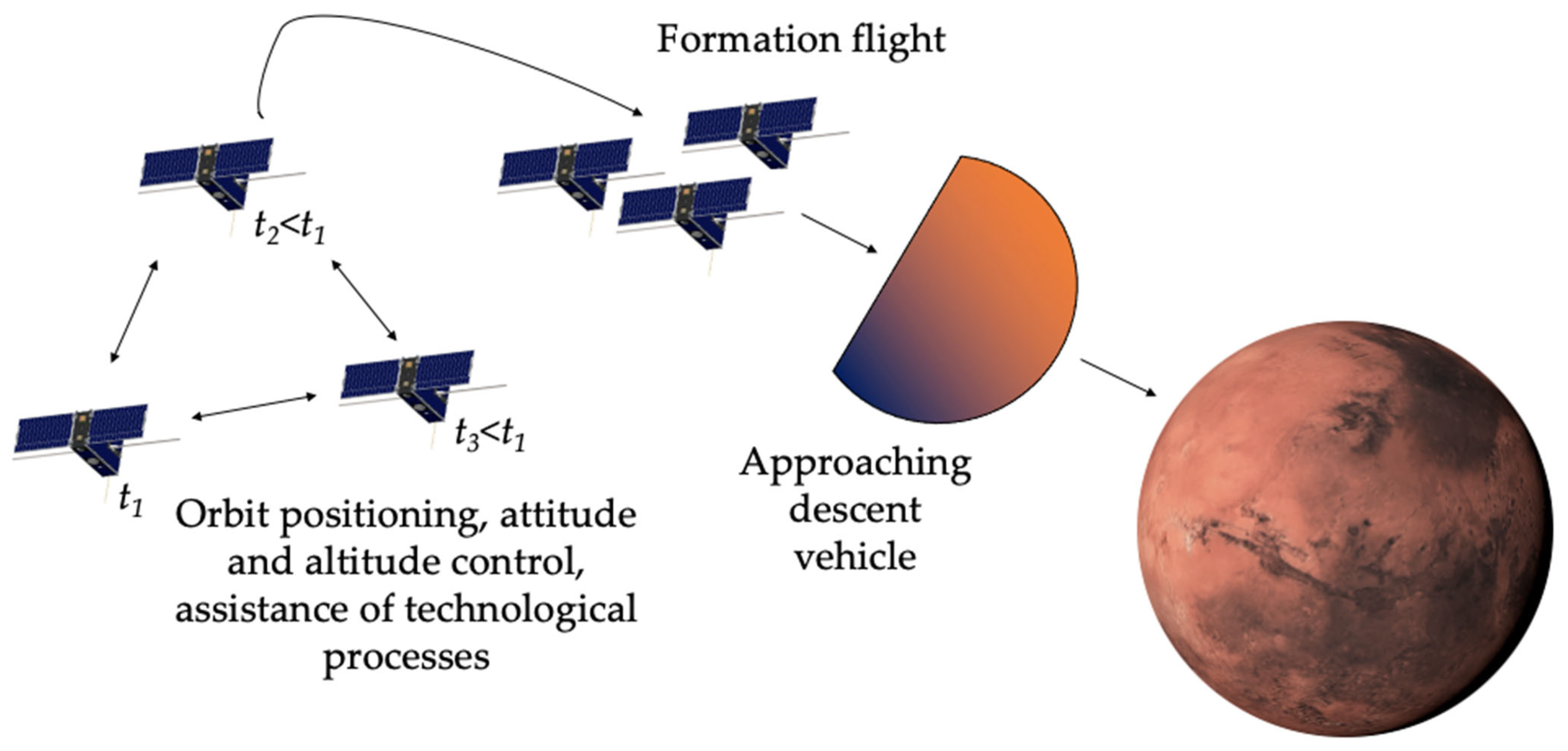
5]. During this proposed mission, a cluster of small satellites, once launched, performs manufacturing activities in space (see
Figure 1). Their operation necessitates the mentioned maneuvering capabilities throughout the active phase of the mission. Satellites involved in this task might operate at distinct time intervals (in
Figure 1 denoted as
t1,
t2,
t3). That means these satellites can be launched in different batches. Once the technological processes aboard each satellite conclude, all units converge into a single descent vehicle scheduled frequently to deliver the payload safely back to the surface of the dedicated natural space object.
To carry out the maneuvers mentioned for assisting the proposed space mission, propulsive forces need to be generated in multiple directions. Given the constraints imposed by small form-factor satellites, a suitable solution involves employing a propulsion system that enables precise control over the direction of the propulsive forces using a single thruster head [
4].
When considering missions originating from or intended to support human settlements located on distant celestial bodies, several critical challenges arise due to limited resources and restricted technological infrastructure. Furthermore, certain scenarios introduce another crucial challenge—the necessity to be able to operate under exceptionally severe environmental conditions, exemplified by orbital operations around planets like Jupiter [
6]. Therefore, components and subsystems within these small satellites must exhibit robustness against prolonged exposure to extreme surroundings while maintaining high reliability over extended periods without significant degradation.
At present, only a few flight-proven propulsion systems exist that integrate the capability of controlling thrust vector direction within a single compact device [
4]. Notable examples include the pulsed plasma thruster EO-1 [
7], the gimbaled ion thruster BIT-3 [
8], the bi-directional electrodeless plasma thruster (BDEPT), and the electrodeless plasma thruster with magnetic thrust-vectoring (MTVEPT) [
9]. It should be noted that the use of such technologies as the electrospray or laser propulsion systems may pose obstacles and risks for operations in reusable proliferated space systems since these technologies require specific chemicals as propellant or their key parts are hard to be produced in the new settlements around deep space [
4]. Although contemporary iterations of these technologies demonstrate suitability for deployment on small satellites, especially electrosprays, and resilience in demanding environmental conditions, their operations require special techniques and their production requires complicated equipment.
An effective strategy to enhance the maneuverability of small satellites sized below 6U is promised by using an electrodeless plasma thruster (EPT) utilizing the solid-state propellants characterized by high storage densities [
10]. However, this technology is currently under active development [
11]. There is another promising propulsion technology that has a simple design: the thruster can be scaled for a small form-factor satellite, based on which the thrust-vectoring capability has already been demonstrated in space. This technology is a pulsed plasma thruster. There are different types of these thrusters differing in structure and the propellant state utilized [
12,
13,
14,
15,
16,
17,
18]. In this study the coaxial ablative pulsed plasma thruster (PPT) is selected as a base technology [
19]. Implementing PPTs that incorporate built-in thrust-vectoring functionality represents a viable alternative solution for assisting satellites in executing complex maneuvers essential for dynamic space missions [
20].
This study undertakes a thorough exploration of a new approach aimed at enhancing both the reliability and operational lifespan of pulsed plasma thrusters of coaxial geometry, enabling thrust-vectoring capability (TVC). It is suggested to implement the use of multiple spark plugs integrated into a single thruster head to enhance the ignition performance of the PPT and provide the capability of controlling thrust vector direction. The proposed approach demonstrates potential for achieving uniform propellant ablation and multidirectional thrust vector capability, constrained solely by engineering limitations. This approach can be especially interesting for extending mission durations and offers flexibility in satellite maneuverability for small form-factor satellites.
It should be noted that the main focus of this study is to present the proof of the concept of using the distributed sparking plug system in the pulsed plasma thrusters for distributed ignition of the discharge and for controlling the direction of the exhausted plasma flows without applying the external systems, for example, a magnetic nozzle, that can be found in the work by Fedorova et al. [
20]. These objectives are demonstrated in the study by providing graphical and statistical data. The development and calibration of a thrust measurement stand for measuring small lateral forces is outlined as the further stage of the development of the PPT with the integrated TVC.
In the following article, in
Section 2, the PPT’s principles of operations are discussed. In
Section 3, the concept of the PPT with multiple spark plugs is introduced. In
Section 4, the experimental setup parts, more specifically, the design of the thruster head test and the testing facility, are considered.
Section 5 presents the methodology of the experiments conducted. In
Section 6, the results of the experiments are presented. In
Section 7, an extensive discussion of the results of the experiments and the proposals for the implementations of the results and further investigations are presented.
Section 8 presents the conclusion.
2. PPT Principles of Operation
There are different variants of ablative pulsed plasma thrusters categorized based on their electrode configurations and the propellant type [
21,
22]. In this study, the coaxial geometry of the PPT that utilizes the solid-state propellant is considered. This type of propulsion is characterized by two main steps of thrust generation—the ionized particle generation, whose process is initiated by means of the surface discharge, and the electromagnetic and thermal acceleration of the propellant for thrust generation. The thrust-vectoring capability in this type of propulsion has been studied relatively extensively, and some of the approaches reached the level of flight demonstration [
4,
7,
23]. The following discussion on the principles of operation is devoted to the coaxial type of pulsed plasma thrusters.
2.1. Discharge Ignition
Discharge ignition constitutes a core aspect of plasma-based propulsion systems, particularly pulsed plasma thrusters (PPTs), fundamentally shaping their performance and efficiency [
24,
25,
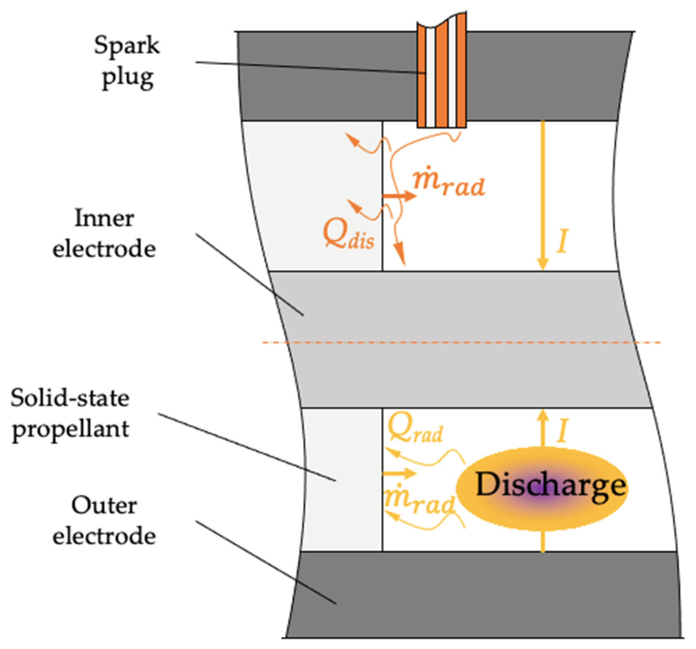
26]. In the case of the PPT, the ignition process begins with the application of a high-voltage electrical pulse between two electrodes—an inner and outer—separated by a dielectric part usually fabricated from a polymer-based material serving as the propellant (see
Figure 2). Upon exceeding a critical electric field intensity, surface-dispersed sparks appear across the dielectric’s boundary, initiating an evaporation and ablation sequence followed by ionization of the vaporized material. Subsequently, this ionized medium facilitates conduction of the electric currents between the electrodes, intensifying the degree of ionization in the evaporated and ablated propellant. This ionized medium forms a low-resistance plasma bulk bridging the electrodes, accompanied by intense localized heating and expansion of the ionized gas. Initially, the rate of the propellant evaporation and ablation,
, stems directly from the thermal energy,
, released by the spark discharge. Thereafter, continued evaporation and ablation proceed at a rate,
, driven by radiative heating,
, emanating from the rapidly accelerating, ionized propellant stream traversing the discharge channel.
While both radiative and thermal processes cause the solid-state propellant to be ablated, the ratio of the contributions of these processes to the ablation may differ depending on the geometry of the discharge channel and electrical characteristics. For example, for the coaxial ablative pulsed plasma thruster with a gap width between electrodes of d = 8.5 mm and initial voltage U = 1.5 kV, the characteristic time for radiative heating is about 2 μs, which is less than the characteristic thermal conductivity time that is approximately 1 s. The gap width influences this ratio in the following way: the reduction in the gap width leads to the increased electric field strength and intensification of the initial surface discharge stage, but may worsen the homogeneity of plasma distribution during multichannel ignition for the discharge channel of small-size (<20 mm) and relatively low electric fields (<5 kV). Thus, the increase in the gap width leads to the prevalence of the thermal processes over the radiative ones during the ablation of the solid-state propellant.
Several critical parameters significantly influence the ignition process in pulsed plasma thrusters (PPTs). Primarily, electrode geometry determines the spatial distribution of electric fields. A specially designed electrode—the igniter—can help minimize arc-related losses along the discharge channel while concentrating electric field lines within the active region, thereby optimizing the initial evaporation and ablation of the propellant.
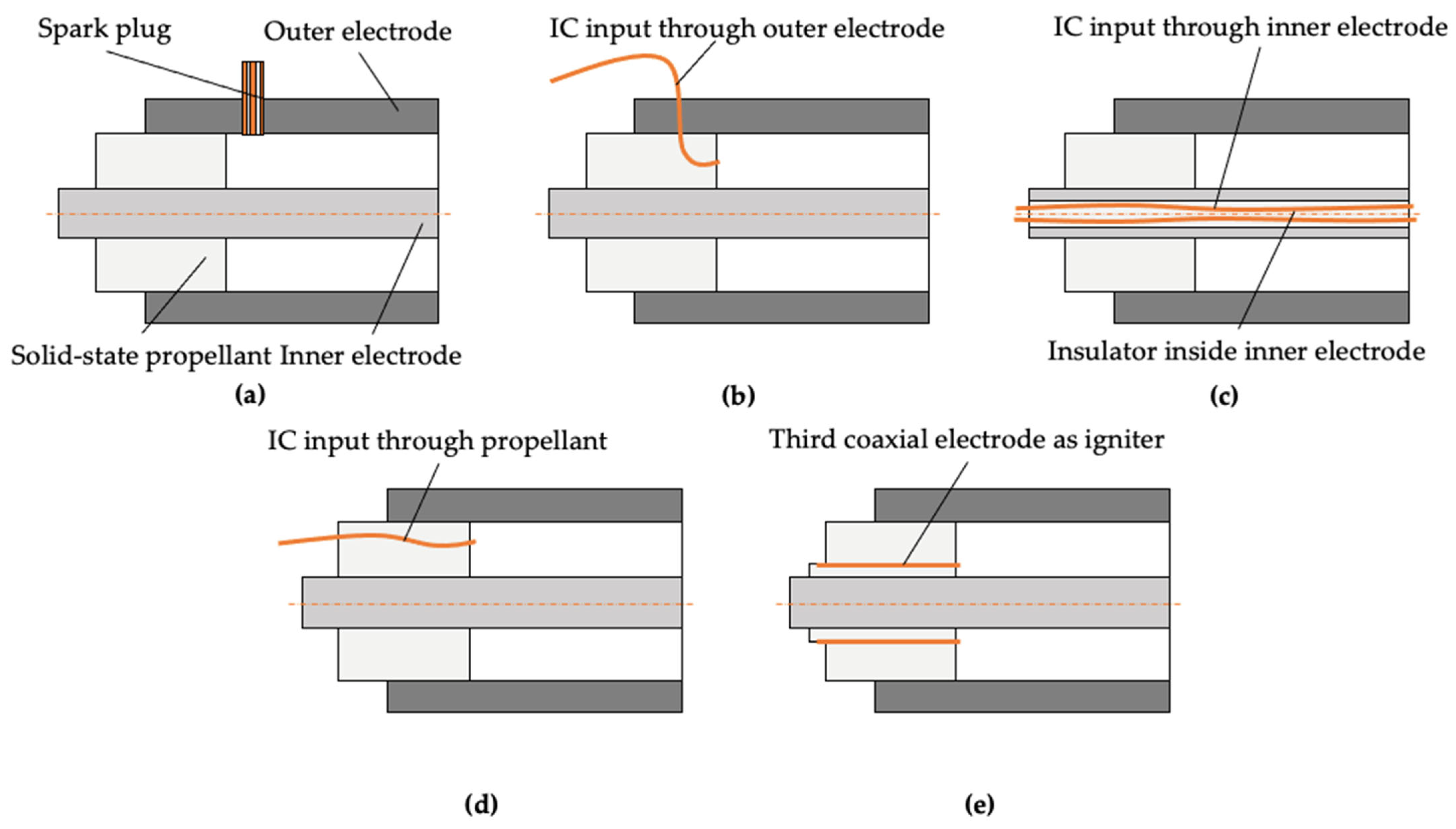
Over recent decades, researchers have investigated various strategies to enhance spark generation in PPTs (see
Figure 3) [
27,
28].
The approaches include the placement of spark plugs near the propellant surface (see
Figure 3a), which improves local field strengths and triggers efficient ignition sequences. Insulated cables inserted through the outer electrode can establish sharper potential drops (see
Figure 3b). Initial spark generation at the exhaust region utilizes downstream effects to augment propellant utilization (see
Figure 3c). Embedding an insulated cable directly through the propellant can allow the reduction of energy loss (see
Figure 3d). Some architectures utilize a third coaxial electrode dedicated to ignition, offering additional control over the ignition process (see
Figure 3e). These methods collectively help to facilitate the ignition process, minimizing inefficiencies and maximizing thrust output per unit charge delivered. Continued research explores hybrid solutions integrating these approaches to meet emerging demands in advanced space propulsion systems.
Secondly, dielectric properties play a crucial role. Materials such as polytetrafluoroethylene or polyimide commonly serve as propellants due to their favorable electrical insulation properties and thermal stability resulting in an effective process of ablation and evaporation. Finally, ambient conditions such as pressure in the discharge channel, temperature of the propellant and the electrodes, and its composition also impact ignition behavior. Pressure alterations may facilitate easier breakdown initiation depending on the discharge channel geometry, whereas elevated temperatures accelerate gas ionization kinetics, reducing the necessary input energy.
Despite advancements in the understanding of discharge ignition in PPTs, challenges persist in achieving robust and reproducible ignition across diverse operating modes. Fluctuations in the delay period between voltage application and actual spark formation introduce uncertainty into thrust generation cycles in repeated high-frequency firings, potentially compromising overall performance of the thruster. Additionally, thermal gradients generated during ignition propagate through adjacent components and can result in mechanical stress and contribute to accelerated wearing phenomena that may result in the failure of the propulsion system.
Overall, the interplay between geometric, material, and operational variables makes discharge ignition in PPTs a subject of ongoing research and developmental interest, and requires unconventional approaches for achieving a stable and predictable discharge ignition and thruster operation.
2.2. Thrust Generation
Ablative pulsed plasma thrusters refer to the electromagnetic and thermal types of electric propulsion systems utilizing solid-state propellants [
29]. The thrust in this type of propulsion system relies on brief bursts of concentrated energy to trigger ablation and evaporation events on the surface of the propellant, leading ultimately to ionized plasma formation.
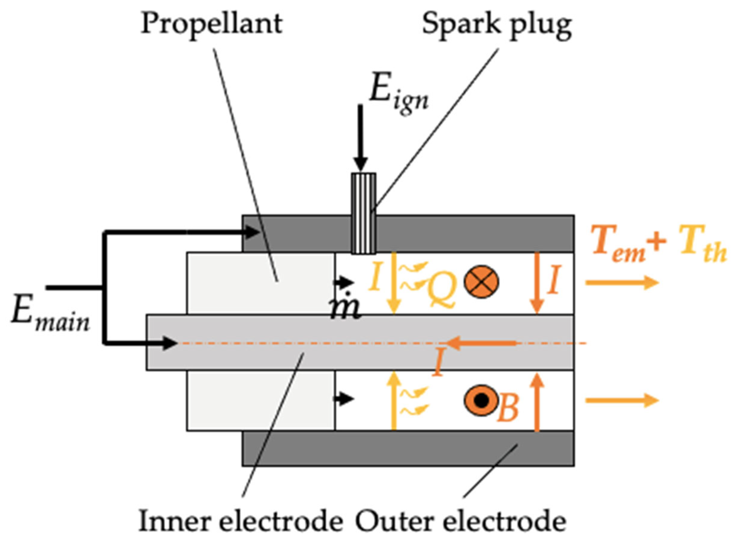
Initially, an external stimulus provides a targeted dose of energy,
, directed towards the propellant surface (see
Figure 4). This energy can be inputted via electrical arcs or lasers. These energy inputs initiate localized temperature spikes sufficient enough to start the phase transformations within microseconds on the surface of the propellant. Subsequent rapid ablation and evaporation ensue, culminating in the generation of a hot, dense cloud of charged particles characterized by elevated temperatures and pressures. Propelled forward by inherent thermodynamic forces—generating the thermal part of the thrust,
—coupled with additional influence exerted by ponderomotive force—generating the electromagnetic part of the thrust,
—this ionized medium expands dynamically throughout the discharge channel and then exhausts from the thruster (see
Figure 4).
There is still no solid and widely accepted theory describing the processes of plasma acceleration in the coaxial ablative pulsed plasma thruster. In this work, it is hypothesized that the plasma acceleration occurs due to both the thermal pressure (the dominant mechanism at high currents) and the electromagnetic forces (
j ×
B), with their relative contributions depending on the operating mode. The main energy input into discharge,
, is performed through the electrodes by means of heating the propellant,
, through the current flowing through the ionized medium,
j(
, and through the ponderomotive force increasing the kinetic energy of the charged particles (see
Figure 4).
To maximize the efficacy of the thruster, engineering efforts can be focused on optimizing geometries associated with both the channel and exhaust region.
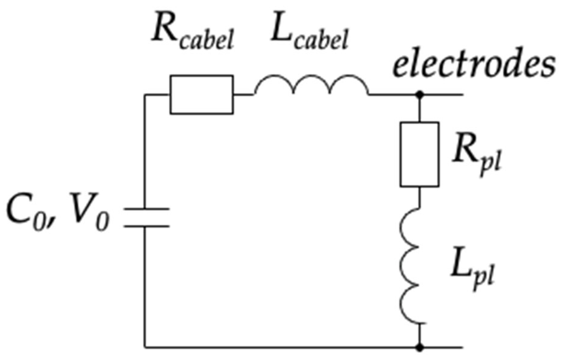
Ablative PPTs represent a system comprising an acceleration channel made up of two electrodes, an energy storage device usually implemented as a capacitor, a propellant, and an ignition device. After the discharging of the ignition device, when initial charge particles appear in the channel, the PPT can be represented as the equivalent electrical circuit (see
Figure 5).
It is evident that damped oscillations will occur in such a circuit with initial voltage
and zero current
. Then, the operation of the pulsed plasma thruster can be described as follows. At the initial moment of time, when the voltage is high and there is still no current, electrons are accelerated in the acceleration channel perpendicular to the outlet direction (from one electrode to another), experiencing collisions with neutrals and ionizing them. In doing so, the expansion of the charge particles will only proceed under the action of a gas-dynamic pressure gradient, which will not result in a significant change in plasma volume due to the small characteristic timescale of the discharge—of the order of units of microseconds. As the discharge develops, the current flowing through the plasma increases, causing an increase in the induced magnetic field, which in turn deflects the trajectories of the charged particles, directing them beyond the boundaries of the channel. Thus, in first approximation, the process of propellant acceleration in the PPT can be described using Newton’s Second Law:
where
is the propellant mass in the channel,
is the velocity of the substance flow,
is the time of the propellant flow through the channel,
is the inductance per unit length of electrodes,
is the current.
In order to determine the propellant mass in the channel, the following empirical dependence can be used:
where
is the empirically obtained coefficient and
is the discharge energy.
The determination of the system current is possible by solving the loop equation:
where
is the capacitance of the capacitor,
is the resistance of the loop, and
is the inductance of the loop.
Solving Equation (3) yields two solutions describing the aperiodic and periodic damping processes of current oscillations in the system. Since the operation of low-power PPTs involves only periodic modes, it is appropriate to consider only the following solution:
where
,
,
.
The main thrust characteristics of the PPT are the impulse of force and specific impulse. The former can be obtained by integrating Equation (1) over time. It should be noted that
can be described by the growing branch of a parabola of the following form:
where
and
are arbitrary coefficients.
This is because the value of inductance grows as the charged particles move towards the channel exhaust region according to the kinematic law of plasma motion:
where
is the initial moment of time and
is the ending moment of time.
Based on Equation (6), it should be noted that the thrust profile at the exhaust region of the PPT depends on the profile of the mass of the propellant ablated and evaporated at the moment of the discharge ignition.
The specific impulse of the PPT can be determined as follows:
The alternative form of notation of Equations (6) and (7) looks as follows:
where
2.3. Thrust-Vectoring Approaches in PPT
In recent years, thrust vector direction control has seen significant advancements in the field of electric propulsion [
30,
31,
32]. Pulsed plasma thrusters with TVC can be a pivotal technology for precise spacecraft maneuvering. PPTs operate by emitting bursts of charged particles, unlike the continuous flows in most types of electric propulsion [
33]. The effective control over the orientation that can be provided by this type of thruster may enhance satellites’ maneuverability, enabling precise adjustments in attitude, orbital corrections, and approaching maneuvers [
34].
Various strategies contribute to achieving thrust vector direction control in the PPT [
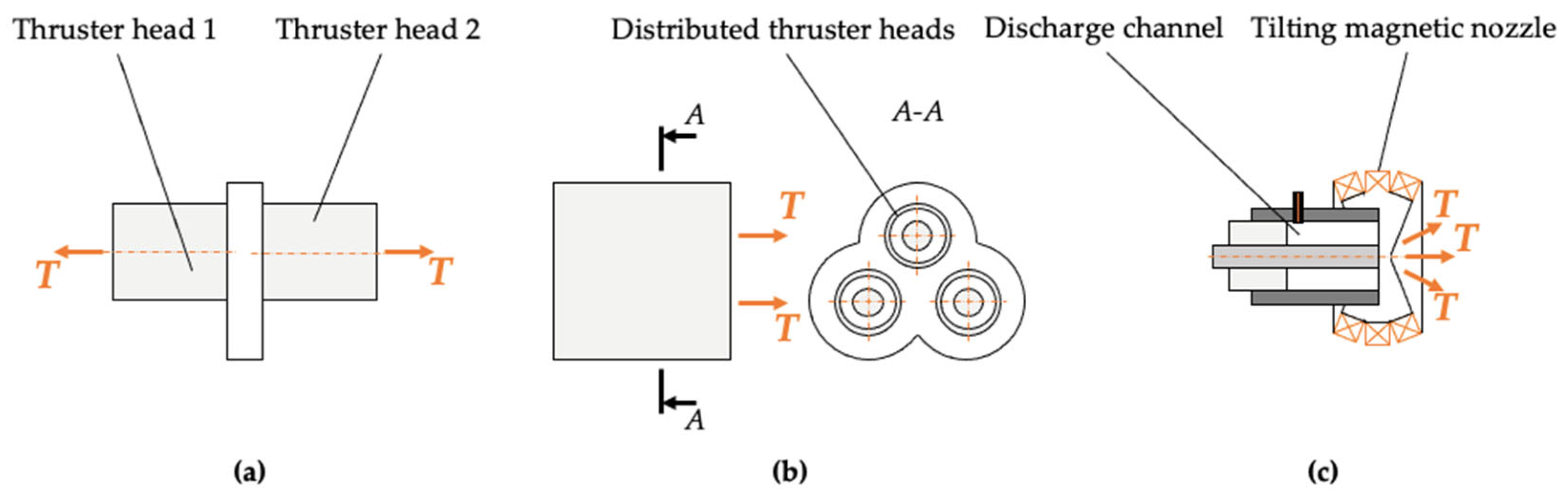
4]. There are three experimentally and in-orbit tested approaches for TVC in PPTs (see
Figure 6). Thrust vector direction control can be achieved by using two and more plasma sources within a single propulsion system (see
Figure 6a). Such an approach has been tested in space with the EO-1 thruster and demonstrated the capability to generate propulsive forces in two directions [
7]. The multiple plasma sources can be integrated into a single propulsion system with a common outer electrode providing the capability of generating the distributed propulsive forces over a certain surface (see
Figure 6b). Another approach of realizing TVC in PPTs is the use of an externally applied magnetic field that guides the path of plasma jets, steering them along the main thruster axis (see
Figure 6c) [
20]. The incorporation of an externally applied magnetic field has been demonstrated to facilitate enhanced directional control over exhausted plasma plumes, and can ensure optimal alignment relative to desired trajectory vectors.
Some prospective approaches for the realization of thrust-vectoring capability in PPTs include electrode shape modifications and modifications of the propellant density profile. The later approach is studied in this work by the implementation of three spark plugs in three different locations over the surface of the solid-state propellant to generate uneven distributions of propellant density in the channel that result in a nonuniform thrust profile generation at the exhaust region of the thruster.
3. PPT with Multiple Spark Plugs
3.1. Multiple Spark Plugs Approach
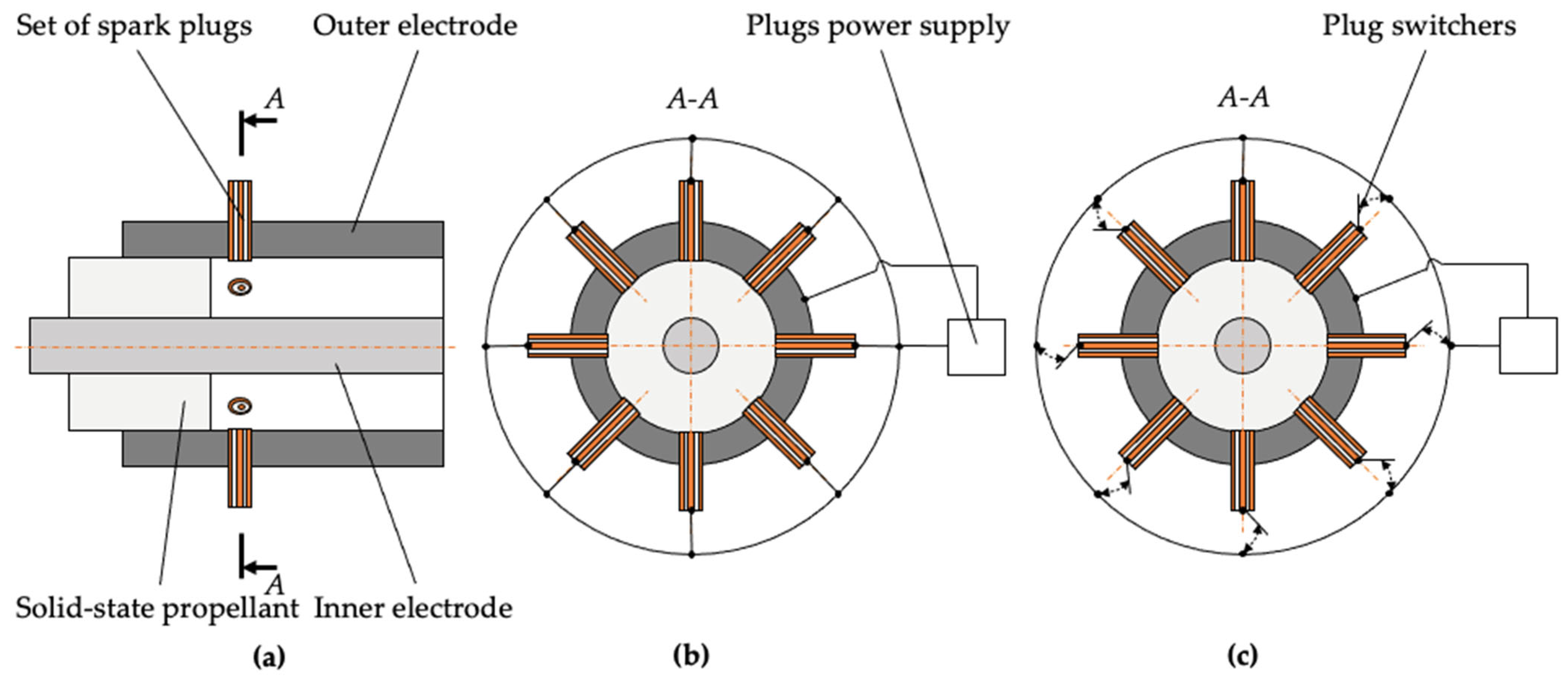
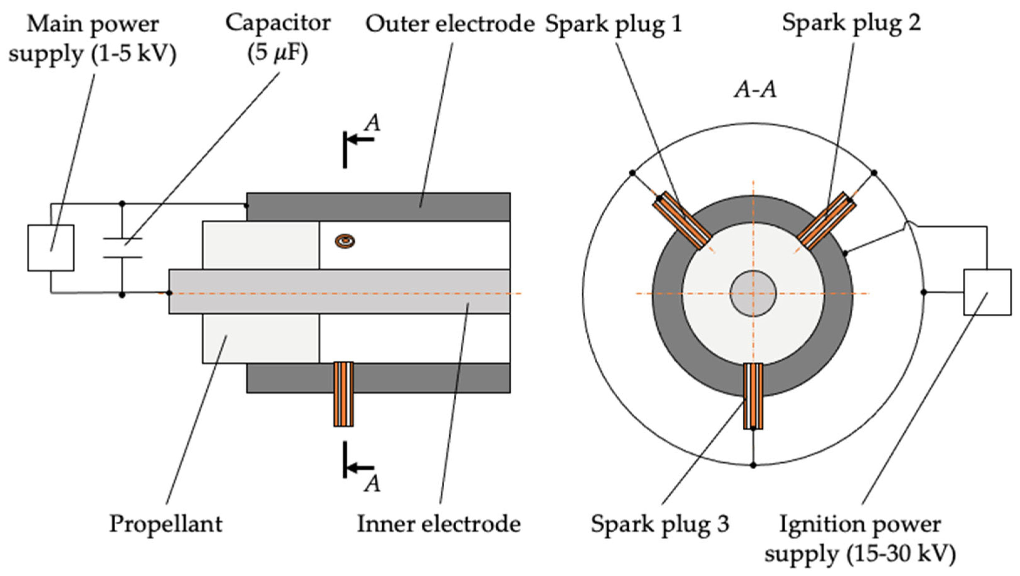
To increase the reliability and longevity and add the capability of controlling the direction of the thrust vector generated within a single thruster head, a pulsed plasma thruster utilizing solid-state propellant with multiple spark plugs is proposed (see
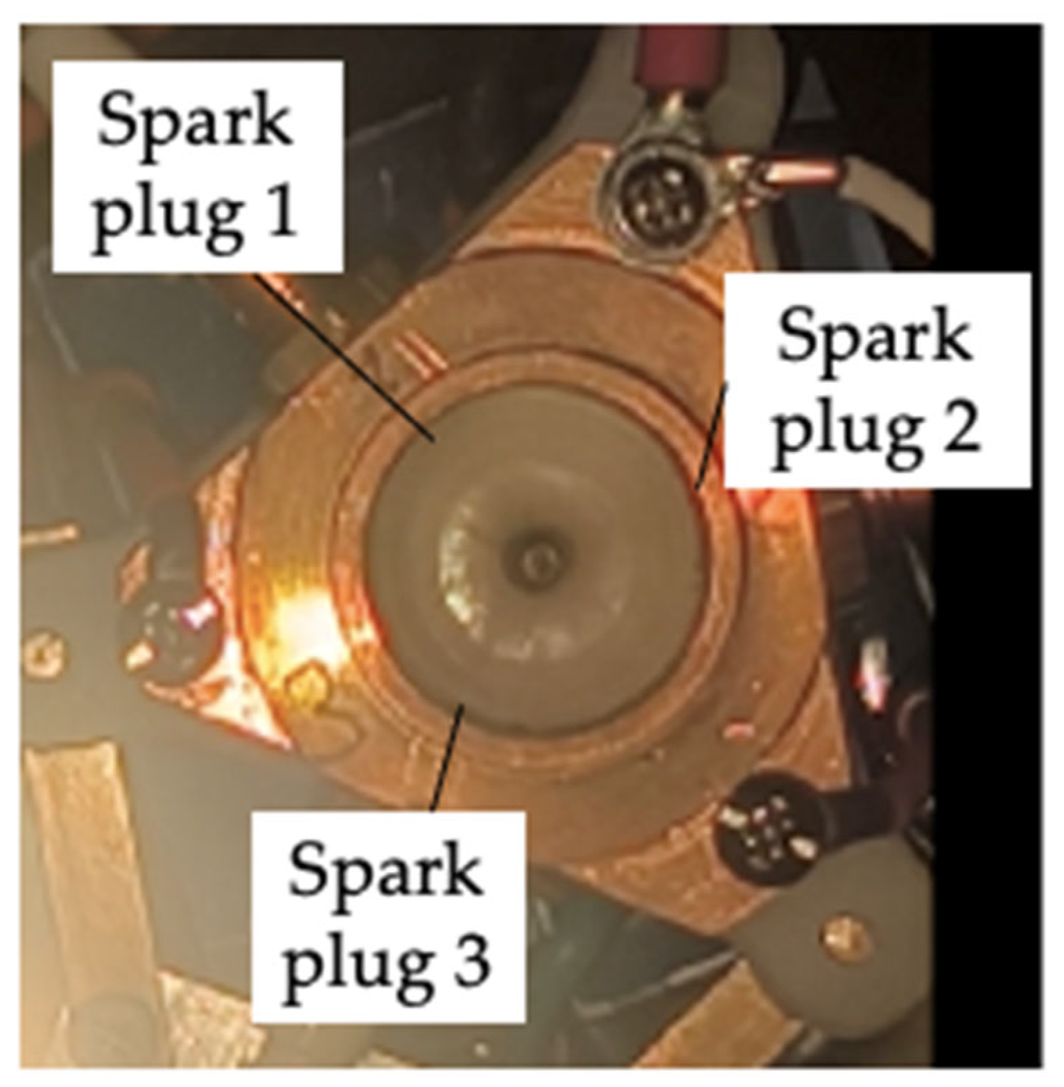
Figure 7). The thruster consists of the following parts: the hollow outer electrode, in the inner cavity of which the hollow solid-state propellant is placed, in the inner cavity of which the inner electrode is placed. The outer and inner electrodes constitute the coaxial channel along which the distance between the inner surface of the outer electrode and the outer surface of the inner electrode is equal. The coaxial channel that is formed by the outer and inner electrodes is closed at one end by the solid-state propellant. The other end is open to the surroundings. The outer and inner electrodes have an electric connection with the main power supply. At the vicinity of the surface of the propellant, there are multiple through holes in the outer electrode through which the set of the spark plugs is inserted. The spark plugs are used to affect the surface of the propellant to cause the propellant ablation and evaporation and to generate the initial charged particles. The spark plugs that constitute the set can be either electric or laser spark igniters. In the case of the use of electric spark plugs, their leading heads are located at the vicinity of the inner surface of the outer electrode cavity. In the case of the use of the laser spark igniters, their leading heads are located a short distance from the inner surface of the outer electrode cavity to minimize the contamination of the laser spark igniters leading heads by by-products after the discharge ignites over the propellant surface. In addition, the laser spark igniters’ main axis can be at an angle to the surface of the propellant, whereas the main axis of the electric spark plug can be parallel to the surface of the propellant.
In the proposed design, the spark plugs have an electric connection with the ignition power supply (see
Figure 7). The ignition power supply is used to generate controlling signals on, and provide the energy to, the spark plugs. The number of ignition power supplies can be equal to the number of spark plugs or can be in other variations to it. The number of spark plugs is limited by engineering constraints in placing the plugs within the through holes of the outer electrode.
The number of plugs determines the number of directions in which the thrust can be generated. The distribution of the spark plugs over the surface of the solid-state propellant allows the generation of nonuniform profiles of the propellant densities that allow control of the thrust profile at the exhaust region. This results in the capability of controlling thrust vector direction.
Comparing the proposed approach of organizing the coaxial ablative pulsed plasma thruster head with the classical scheme of a PPT can reveal the multiple advantages of the former one. The use of distributed spark plugs has several advantages that can become critical for extensive maneuvers in space missions of small satellites of a size less than 6U. Implementing multiple spark plugs positioned along the propellant surface in an ablative pulsed plasma thruster introduces substantial improvements in terms of performance, reliability, and adaptability. The primary advantage lies in achieving uniform ignition across the entire propellant area, thereby mitigating potential inconsistencies caused by uneven heating patterns. This results in more stable and predictable ablation processes, contributing directly to optimized plasma generation and subsequent thrust production. Considering the system as a whole, it results in the long-term predictability of thruster operational characteristics and in reduced risks of unstable work or failure of producing propulsive forces. It is achieved because the use of distributed spark plugs allows ablating and evaporating the propellant over the whole surface, which results in there not being a local excessive use of propellant in comparison to other surface regions. In addition, having redundant ignition points ensures continuity of operation even when certain components fail, thus increasing overall system resilience against failures and the impact from the external objects. Also, finely tuned control over individual spark plugs’ activation timings and intensities permits tailoring energy inputs precisely where needed. As thruster dimensions grow, centralized ignition mechanisms can become progressively inefficient, whereas distributed spark plugs can maintain their efficacy regardless of the thruster dimensions. These cumulative advantages render multi-spark configurations highly preferable for modern spacecraft applications requiring versatile, reliable, and high-performance propulsion solutions.
3.2. Principles of Operations
It is possible to operate spark plugs of the electric igniters type either by using all the plugs permanently connected to the ignition power supply or using the plug switchers (see
Figure 7). In the former case, the thruster is operated in the distributed discharge ignition mode (see
Figure 7b). In the latter case, the thruster is operated in the thrust-vectoring control mode (see
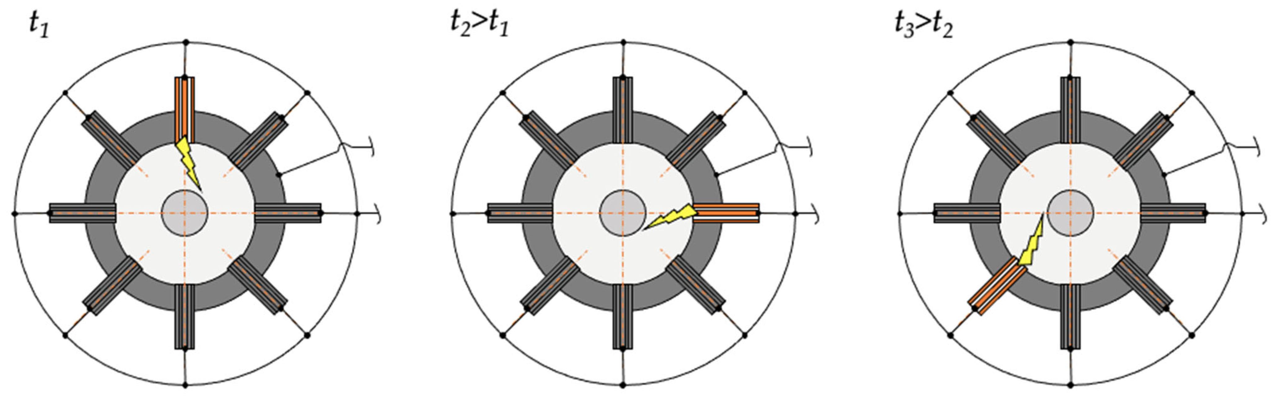
Figure 7c). In the case of thruster operation in the distributed discharge ignition mode, it is supposed that the plugs generate the sparks alternatively (see
Figure 8). That means that at each moment of time, some plugs are in operation while at other moments they are out of use. Thus, the plugs can be operated with the distributed working load that can result in their even wearing and the even utilization of the surface of the propellant. The alternative activation of the plugs is supposed to be a self-sustained process that is not controlled by external actions.
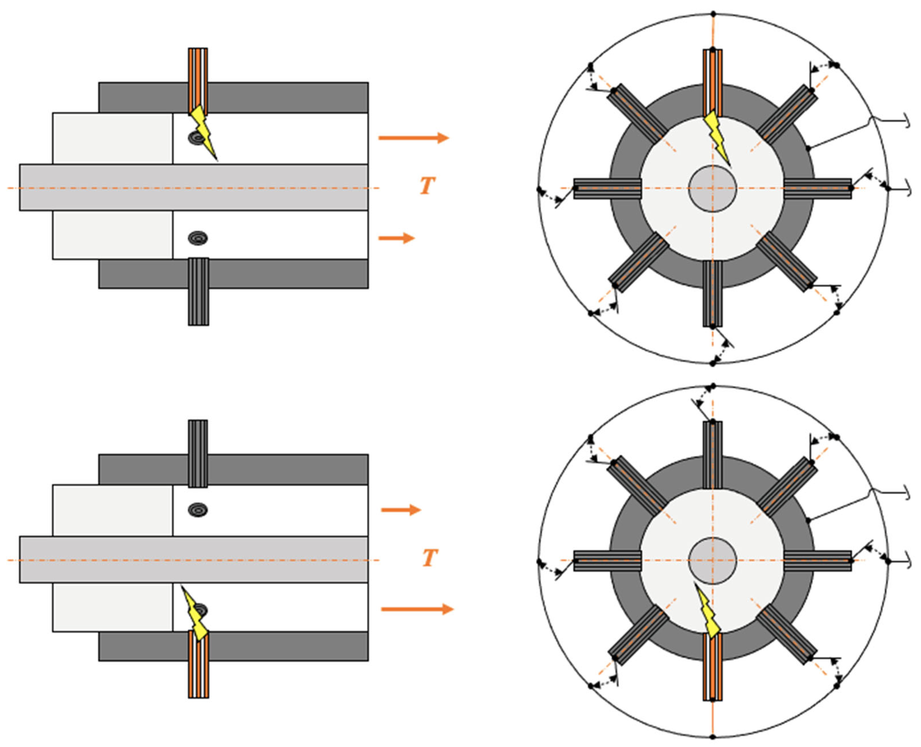
The approach by which the thrust-vectoring is realized in the proposed thruster is electromagnetic (see
Figure 9). That means that the thrust vector direction is controlled by means of electrical and magnetic fields. More specifically, these fields allow altering the propellant density inside the channel and the acceleration of the propellant within the annular projection of the thruster.
The control of the thrust vector direction by physical alterations in the propellant density in the channel of the PPT is realized in that the nonuniform profile of propellant density generated over the surface of the propellant at the initial moment of time creates the nonuniform conditions for the subsequent propellant acceleration both through thermal and electromagnetic forces. These nonuniform conditions are mainly related to the inconsistent propellant density constituting different profiles of charged particles density and electrical conductivity within the annular projection of the channel. This results in unequal heating and ponderomotive force effects on this particle. Thus, the charged and neutral particles occurring in the channel at the specific time are accelerated unequally, resulting in nonuniform profiles of speed and mass flow rates at the exhaust region of the thruster. The nonuniformity of the ablated and evaporated propellant mass at the initial moment of the discharge ignition effect on the thrust is supported by Equation (6). The thrust level generated by the propulsion system is higher at the side where the density of the propellant is higher (see
Figure 9).
This approach of realizing the thrust vector direction control in the pulsed plasma thruster is more advanced than its analogs—the PPT with TVC realized by geometric and electromagnetic approaches. The adoption of multiple spark plugs for thrust vector control in pulsed plasma thrusters represents an approach for reconsidering previous reliance on the use of multiple plasma sources and magnetic fields for directing the propulsive forces. Unlike magnet-based strategies, spark plugs facilitate direct and localized initiation of plasma discharges, yielding better levels of responsiveness and precision in steering the trajectories of charged particles. This direct actuation mechanism eliminates intermediate steps involved in generating magnetic fields, ensuring swift reaction times critical for dynamic flight regimes. Additionally, the elimination of bulky electromagnets or permanent magnets and their ancillary power supply units substantially streamlines system integration efforts, reducing weight penalties that can be unacceptable for satellites of a size less than 6U. The flexible positioning possibilities offered by spark plugs empower tailoring of layouts specifically suited to unique mission profiles, unlocking new frontiers in propulsive optimization that is critical for the missions at the proximity of deep space natural objects. Furthermore, minute adjustments afforded by timed spark intervals yield unsurpassed directional control fidelity that is largely impractical through global variations imposed by external magnetic fields. Complementing these functional gains is the notable reduction in energy expenditure enabled by the discontinuous nature of spark activity versus the sustained current flows demanded by electromagnet arrangements. In addition, the use of multiple spark plugs prevents the unwanted use of energy by small satellites to power the attitude determination and control system that should prevent the rotations generated by the electromagnets or permanent magnets in the case of the mission operating at the proximity to natural space objects that have their own magnetic fields. These factors render the multiple spark plugs approach one of the promising proposals for advancing the state of the art in pulsed plasma thruster technologies.
5. Methodology
All experiments are performed under a vacuum environment with a pressure maintained around 10−4 Pa. Three different operation modes are implemented: firstly, a permanent connection mode where spark plugs remained constantly linked to the ignition power supply, enabling the demonstration of statistically distributed multi-spark ignition with the main discharge and without the main discharge. Secondly, a switcher-controlled firing mode allowed selective triggering of the dedicated spark plugs, facilitating controlled adjustments of the thrust vector direction.
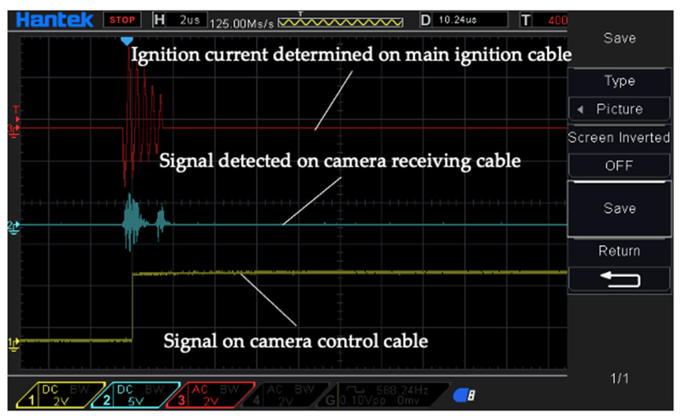
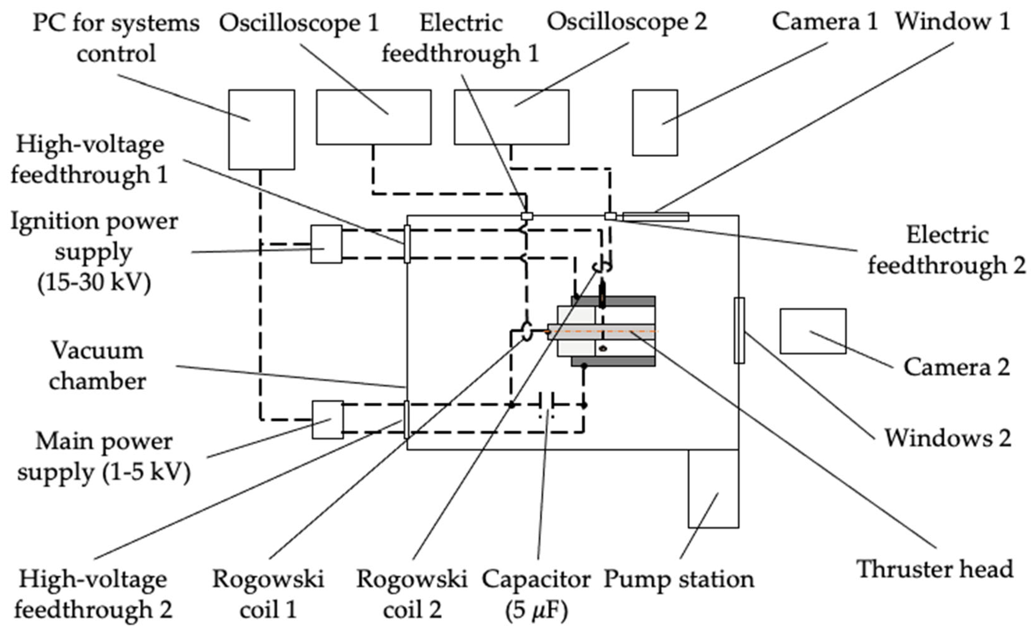
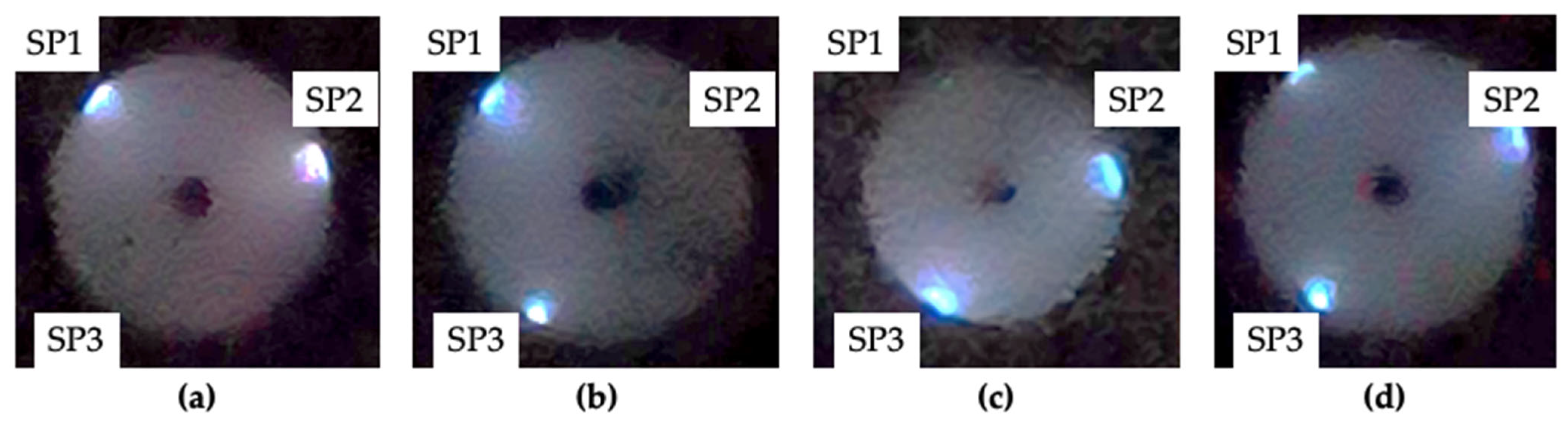
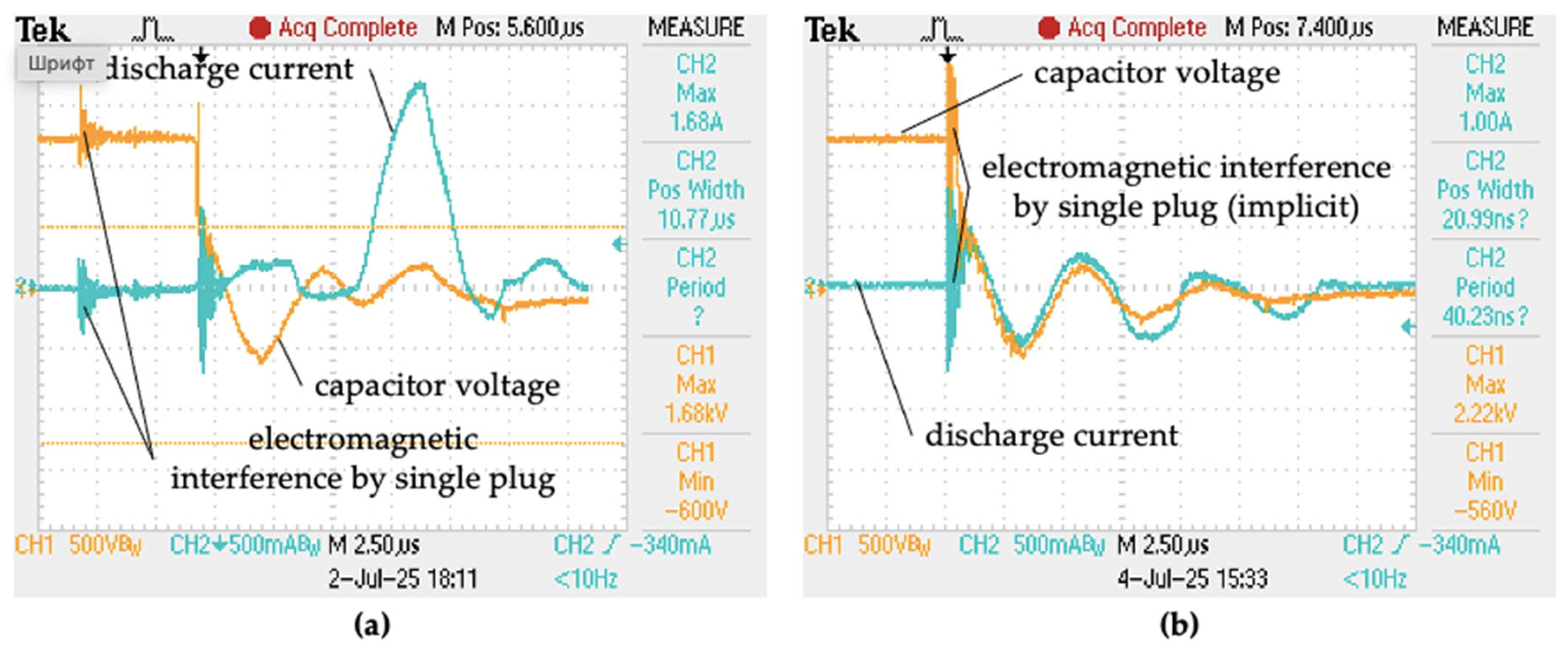
To determine the number of firings for each spark plug, a high-speed camera is placed in front of the thruster head’s exhaust channel. An initial number of impulses is established before setting appropriate voltages for the spark plugs and the main discharge. Once the system is initiated, each spark event is detected by signals from a Rogowski coil. Concurrently, the camera captures images every time the ignition power supply engages the spark plugs (see
Figure 13). After completing the experiments, images and data collected by the oscilloscope are consolidated and analyzed to determine the frequency of firings per spark plug during each test run.
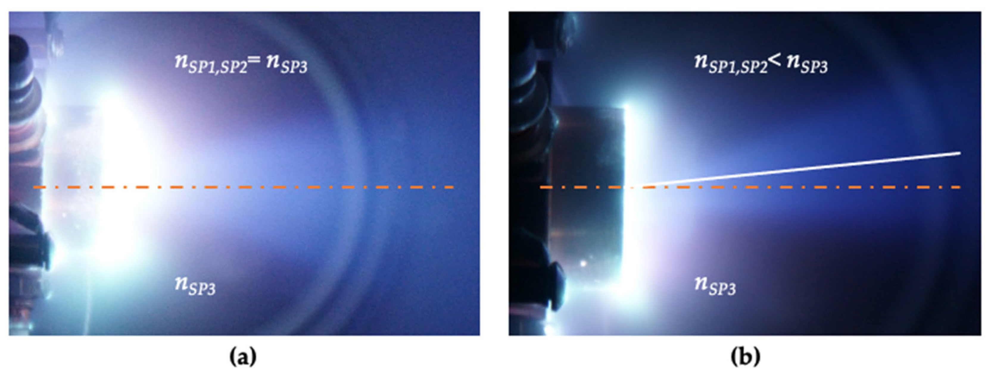
Additional experiments focus on evaluating the capability to control the thrust vector direction. For these trials, the camera is positioned perpendicular to the thruster head’s thrust axis. Experiments are proceeded in single-pulse mode, with defined voltages applied to the dedicated spark plugs and the main discharge. At the moment of firing, the camera takes a picture. Visual inspection of the exhaust plume images then permits determination of any directional changes in the thrust vector.
7. Discussion
The conclusions regarding the statistically distributed nature of spark plug ignitions are derived primarily from electrical diagnostic techniques involving current measurements (see
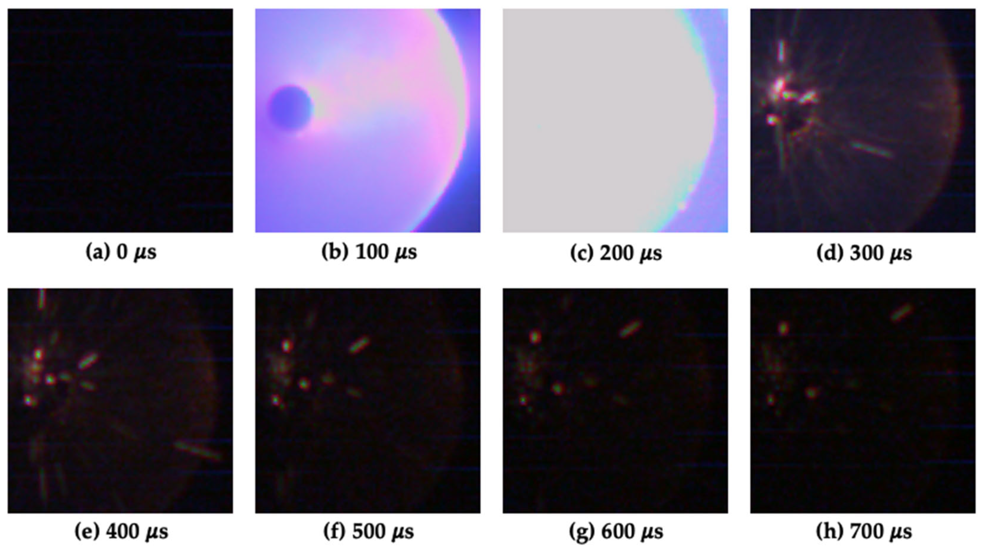
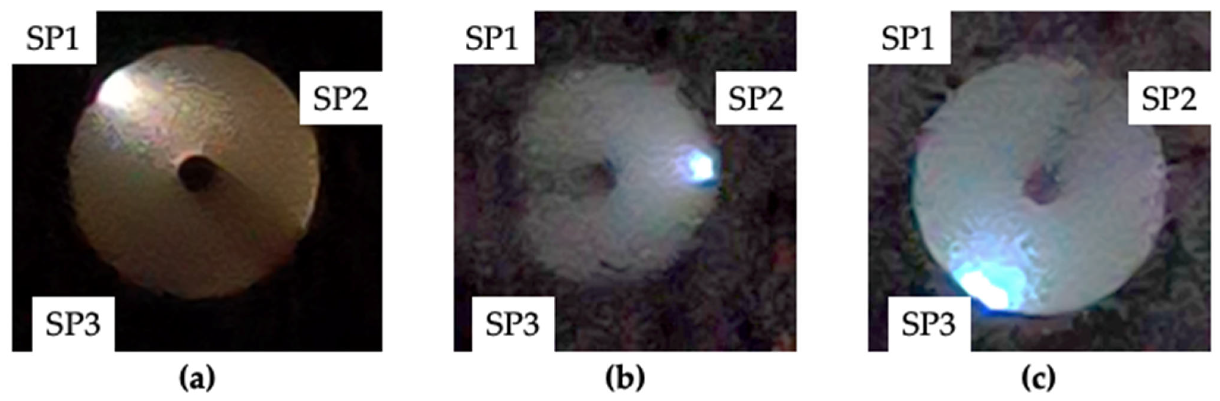
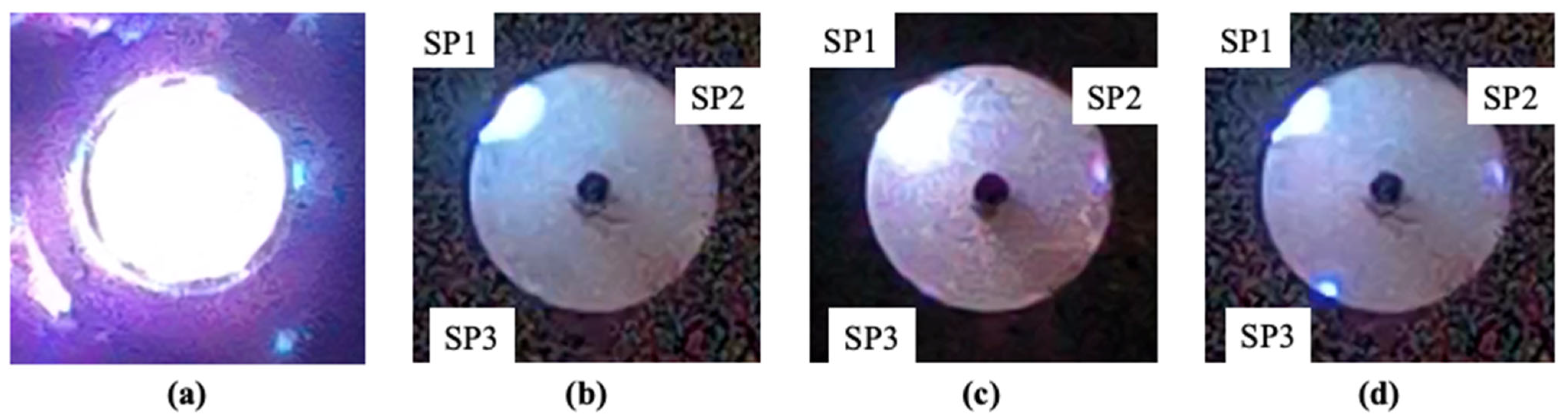
Figure 18). The electrical diagnostics included the Rogowski coils used for each spark plug power supply cable independently. Another method used for determining the statics of the spark plug ignitions is a camera-based approach. This method has proved sufficiently sensitive even though the extremely short ignition times (500 ns) and minimum exposures required for visual clarity exceeded acceptable limits (~20 μs). It is possible to determine the initial place of the discharge ignition based on the pictures taken (see
Figure 19). By using the camera, it is possible to get pictures of the moments of discharge ignition, the main discharge glowing, and the after-discharge electrode destruction (see
Figure 19).
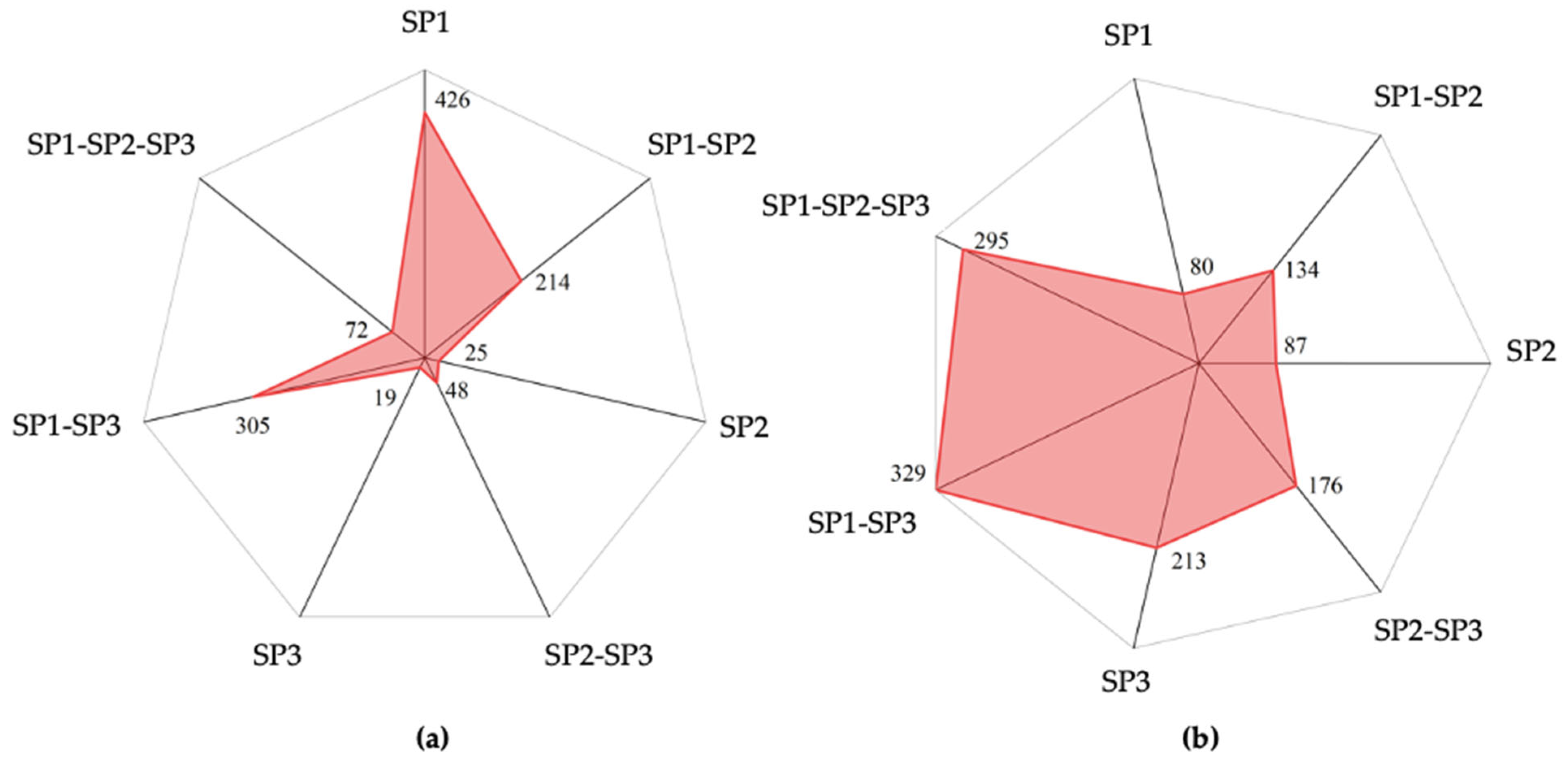
It is revealed that without applying a main discharge voltage, the ignition sequence of spark plugs follows a statistically distributed pattern though it is not as distinctive as when the main discharge is applied (see
Figure 20). So, for 1109 total ignitions without the main discharge voltage applied, the first, second, and the first and third plugs simultaneously show the greatest number of times of ignition. For 1314 total ignitions with the main discharge voltage applied to the electrodes, the first and third plugs simultaneously ignited more frequently than other combinations. At the first instance, the results obtained prove the capability of using the plugs variationally in the statistically distributed mode. Also, the results obtained imply that although statistical distributions may prevail under certain conditions, precision in the fabrication process—both in terms of spark plug design and socket alignment—is crucial for optimal operation. Even when employing the main discharge, statistical distributions might persist, highlighting the need for rigorous prelaunch adjustments and exacting standards during production. The studied configurations for assembling the spark plugs ensure more uniform ignition patterns. By opting for manual commutation instead of automatic systems, it is found that complete control over the ignition process could be achieved. This approach also offers potential benefits for finely tuning the directionality of thrust vectors, enabling targeted ignition of individual spark plugs where needed.
The main hypotheses explaining the statistical nature of ignition with a parallel connection of spark plugs that can be observed in
Figure 20 are as follows. Firstly, micro-inhomogeneities of the dielectric propellant surface can lead to local fluctuations in breakdown field strength among different spark plugs. Secondly, the residual plasma or charged particles from previous discharges can generate nonuniform pre-ionization on the surface of the propellant. Where this pre-ionization is stronger, the corresponding spark plug can be easier to trigger. Additionally, utilizing the carbon-containing propellants, the formation of the carbon deposits on the unignited spark plugs can facilitate their further discharging, while a previously fired spark plug self-cleaned by discharge requires a higher voltage for its subsequent breakdown. Thus, a self-regulating stochastic statistically distributed alternating ignition mechanism can be realized.
In cases where controlled ignition is not essential, implementing a reserve set of spark plugs emerges as a viable solution. Automatic or manual switching mechanisms provide redundancy against failures caused by breakage or abnormal resistances. Such strategies can enhance reliability and extend operational lifespan.
8. Conclusions
This study can be a basis for one of the directions for organizing the reusable proliferated space systems of small satellites by improving the operations of pulsed plasma thrusters. These improvements include features such as the organization of the discharge ignition in the PPT by using the distributed spark plug systems with improved dependability, controllability, and overall performance characteristics. Also, the proposed approach of using the distributed spark plugs and its initial experimental demonstration qualitatively shows the capability to control the thrust vector directions. In addition, by leveraging multiple discharge igniters, it is possible to mitigate risks associated with single-spark plug failures.
It is demonstrated that the use of multiple discharge igniters is a promising approach for ensuring reliable long-term operations for dynamic space missions in terms of system reliability. Also, the use of multiple spark plug igniters can be realized without adding additional mass and volume since they can be integrated within a single thruster head. These igniters can consume less than 1% of the total power for ignition, making them highly energy-efficient. Additionally, they occupy approximately 10% of the volume of the entire propulsion system for satellites smaller than 6U, contributing to increased payload mass. Achieving self-automation has been demonstrated by connecting multiple spark plugs in parallel to the ignition power source. Reducing the ignition power due to the decreased breakdown voltage of the spark plugs in the self-automated mode increases the overall efficiency of the installation. The ability to reserve ignition compensates for the increased weight caused by increasing the number of spark plugs. Additionally, reducing the breakdown voltage allows decreasing the size of the spark plugs, thus not increasing the mass of the installation. It is important to note that after 2000 ignition cycles, the authors record statistically insignificant changes (<1%) in spark plug firing delay and plume uniformity under the simultaneous ignition mode. Visual inspection revealed uniform propellant surface erosion. Long-term endurance tests are required for further verifications.
It is qualitatively demonstrated that the implementation of multiple spark plugs can enable thrust-vectoring capability within the single thruster head of the ablative pulsed plasma thruster. Qualitatively, it is shown that to realize this feature, it is necessary to reduce the discharge current so that there is not an even distribution of surface discharge over the propellant surface but it instead operates in the thermal acceleration mode. In this work, the main focus is on proving the concept of controlling the direction of the plasma plume by the approach proposed. The direct measurements of the thrust levels for the different directions of the thrust vector are the next critically important step.
To further improve ignition consistency, it is proposed to test different spark plugs and the ways of their insertion into the discharge channel. Future research directions include refining predictive models linking physical parameters such as electrode spacing and material properties with ignition results, thereby paving the way for next-generation models of pulsed plasma thrusters.