

OSIRIS4CubeSat—The World’s Smallest Commercially Available Laser Communication Terminal

 , ,
, ,
Abstract
1. Introduction
2. Concept of Laser Communication on CubeSats
3. Terminal Hardware Design
3.1. Link Budget
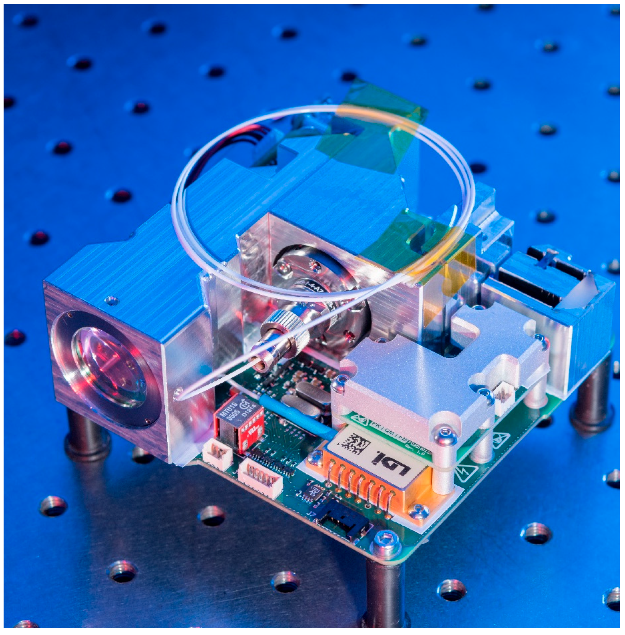
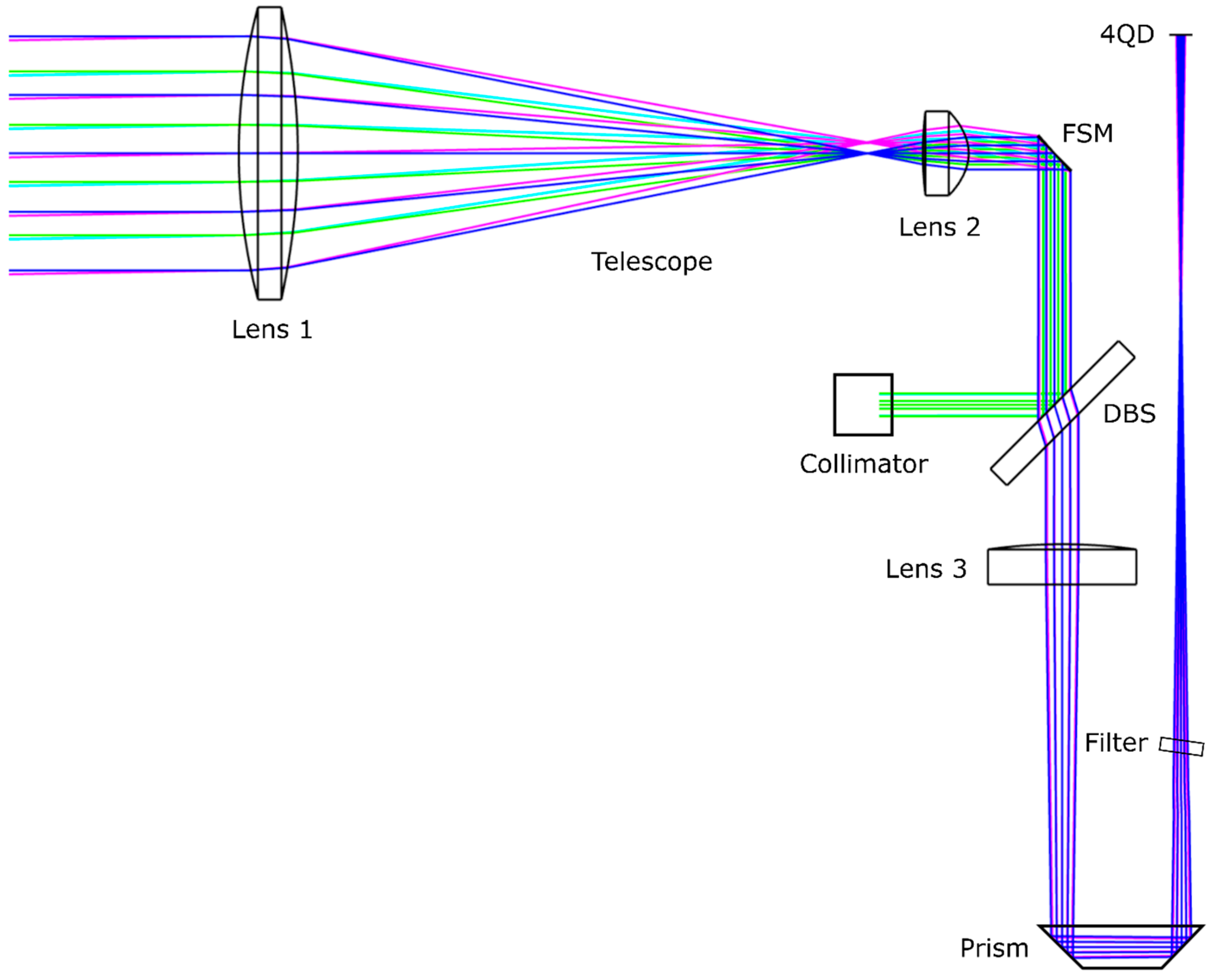
3.2. Optomechanics
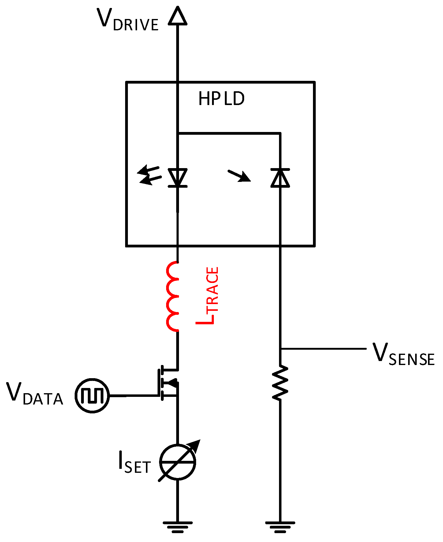
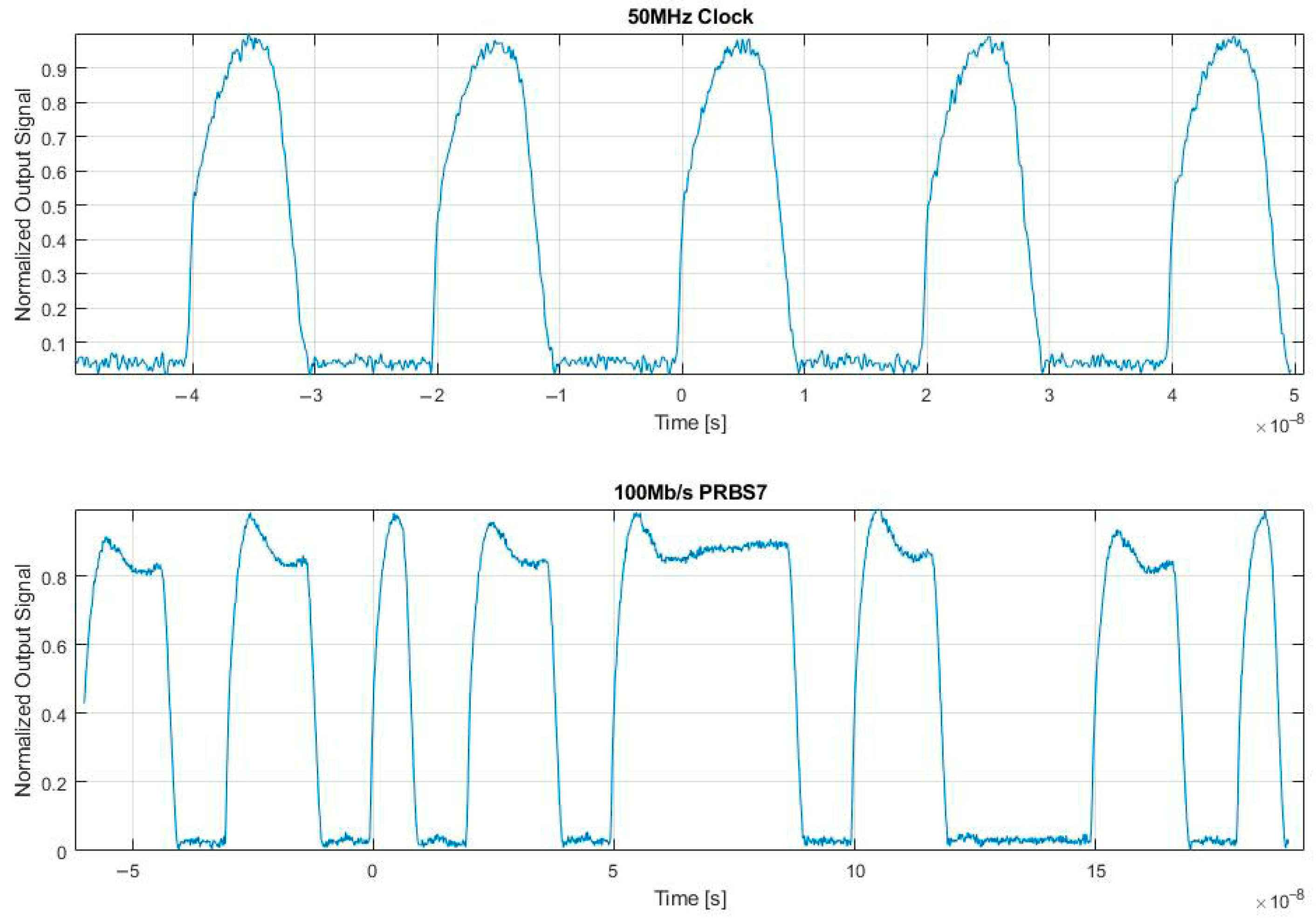
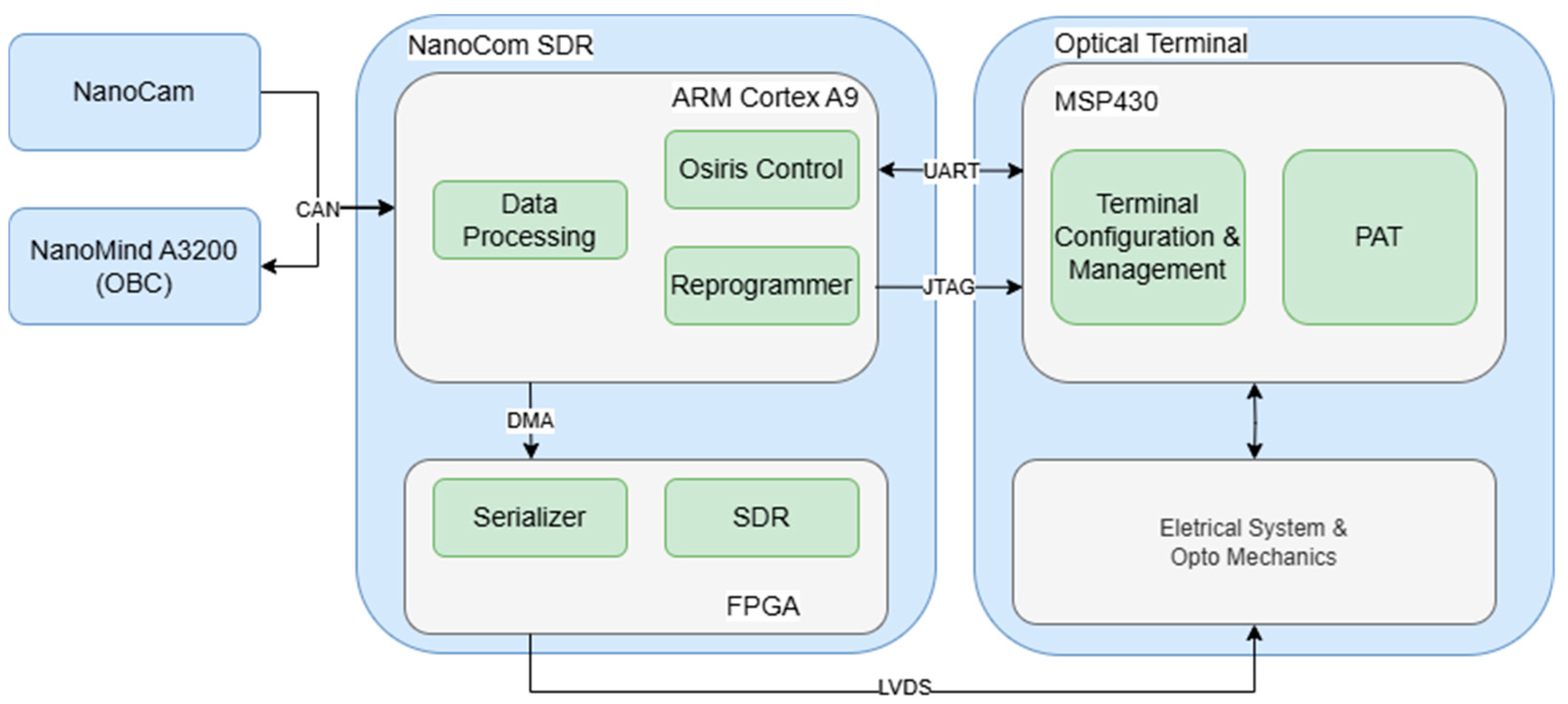
3.3. Electronics
4. Software Concept
4.1. Terminal Firmware
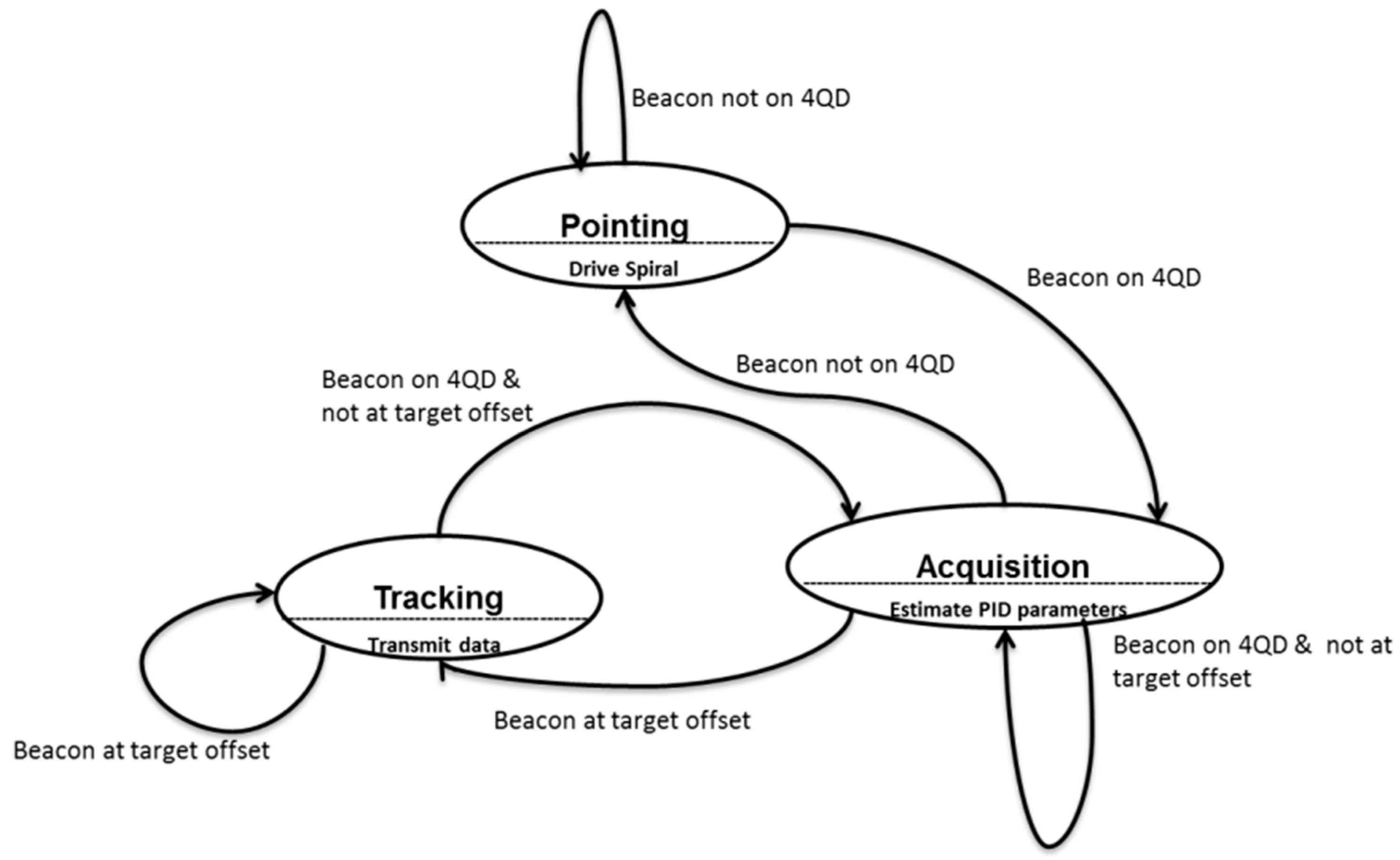
4.2. PAT Control Loop
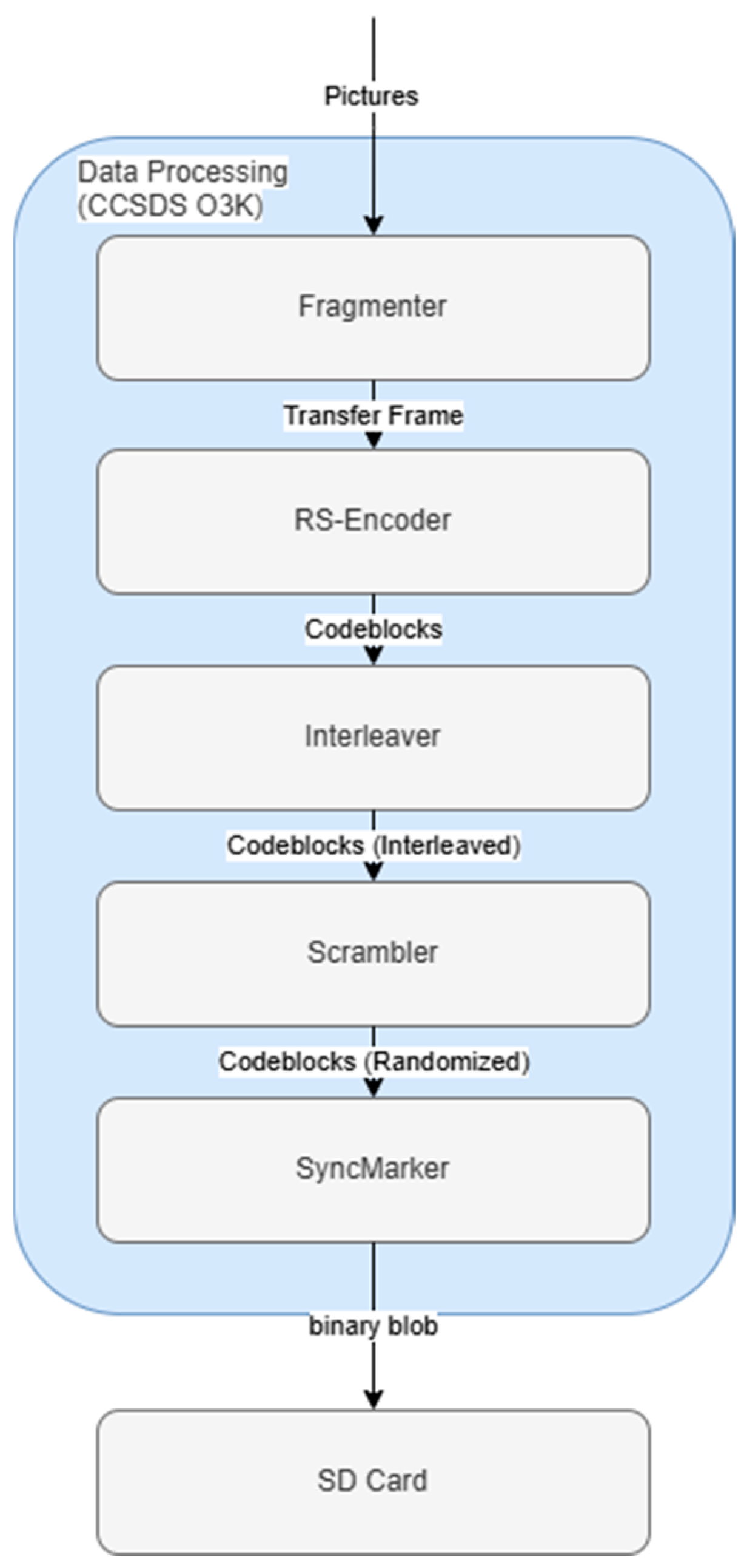
4.3. Channel Coding
4.3.1. OSIRIS Controller
4.3.2. Re-Programmer
4.3.3. Data Processing
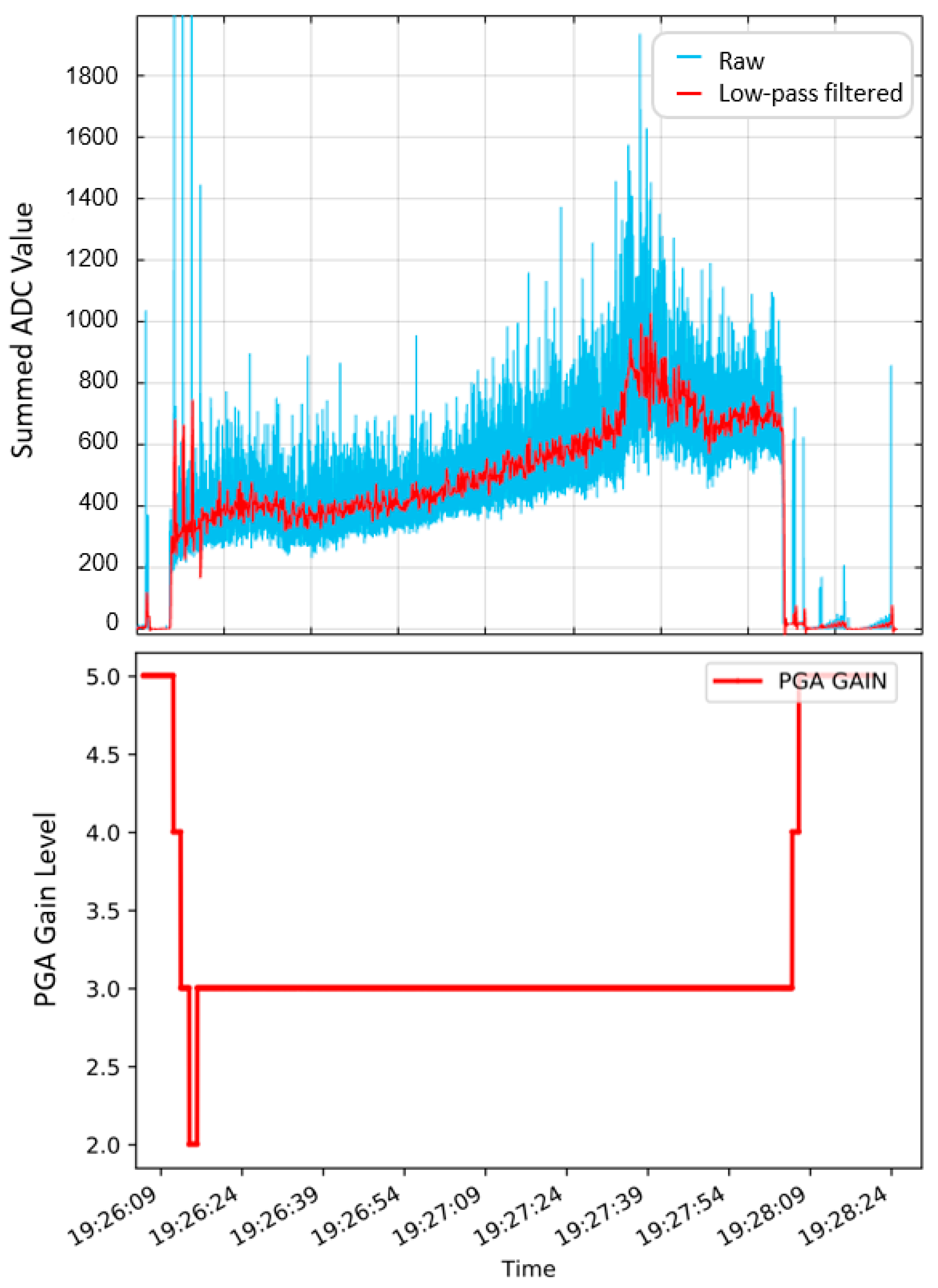
5. In-Orbit Demonstration
6. Discussion and Conclusions
7. Patents
- “Elektrisch-optischer Aufbau” (DE102016221137A1), filed on 26.04.2018, by C. Schmidt.
- “Method for data transmission from a spacecraft to ground via a free-space optical channel” (EP4256726B1 and US20230421251A1), filed on 01.12.2021, by A. Morab Vishwanath.
Author Contributions
Funding
Data Availability Statement
Acknowledgments
Conflicts of Interest
Abbreviations
| 4QD | Four-quadrant diode |
| ADC | Analog-to-digital converter |
| ADCS | Attitude determination and control system |
| BiROS | Bi-spectral Infrared Optical System |
| CAN | Controller area network |
| CCSDS | Consultative Committee for Space Data Systems |
| CLICK | CubeSat Laser Infrared Crosslink |
| COTS | Commercial off-the-shelf |
| CSP | CubeSat space protocol |
| CTE | Coefficient of thermal expansion |
| DAC | Digital-to-analog converter |
| DBS | Dichroic beam splitter |
| DC | Direct current |
| DLR | German Aerospace Center |
| DMA | Direct memory access |
| EDFA | Erbium-doped fiber amplifier |
| EDRS | European Data Rely System |
| FEC | Forward error correction |
| FOR | Field of regard |
| FPGA | Field programmable gate array |
| FSM | Fast-steering mirror |
| FSOC | Free-space optical communications |
| Gbps | Gigabit per second |
| GSOC | German Space Operation Center |
| HPLD | High-power laser diode |
| JTAG | Joint test action group |
| JPEG | Joint photographic experts group |
| LCT | Laser communication terminal |
| LEO | Low earth orbit |
| M1 | Primary mirror |
| M2 | Secondary mirror |
| Mbps | Megabit per second |
| MS/s | Megasamples per second |
| NASA | National Aeronautics and Space Administration |
| O3K | Optical on–off-keying |
| OBC | Onboard computer |
| OGS | Optical ground station |
| OSIRIS | Optical Space Infrared Downlink System |
| OSL | Optical Satellite Links |
| PAA | Point ahead angle |
| PAT | Pointing, acquisition, and tracking |
| PCB | Printed circuit board |
| PGA | Programmable gain amplifier |
| PI | Proportional–integral |
| PRBS | Pseudo-random bit sequence |
| RF | Radio frequency |
| RS | Reed–Solomon |
| Rx | Receiver |
| SDR | Software-defined radio |
| SOCRATES | Space Optical Communications Research Advanced Technology Satellite |
| SPI | Serial peripheral interface |
| SWaP | Size, weight, and power |
| TBIRD | Terabyte Infrared Delivery |
| TCXO | Temperature-compensated crystal oscillator |
| TEC | Thermoelectric cooler |
| Tesat | Tesat-Spacecom GmbH & Co. KG |
| TNO | Netherlands Organization for Applied Scientific Research |
| Tx | Transmitter |
| U | Unit |
| USART | Universal synchronous/asynchronous receiver/transmitter |
References
- Buscher, M.; Brieß, K. Investigations on the Current and Future Use of Radio Frequency Allocations for Small Satellite Operations; Universitätsverlag der TU Berlin: Berlin, Germany, 2019. [Google Scholar] [CrossRef]
- The European Space Agency (ESA). EDRS Overview; ESA: Paris, France, 2024; Available online: https://www.esa.int/Applications/Telecommunications_Integrated_Applications/EDRS/Overview (accessed on 23 May 2025).
- Brashears, T.R. Achieving ⪆99% Link Uptime on a Fleet of 100G Space Laser INTER-satellite Links in LEO. In Proceedings of the Free-Space Laser Communications XXXVI, San Francisco, CA, USA, 30–31 January 2024; Volume 12877. [Google Scholar] [CrossRef]
- Giggenbach, D.; Fuchs, C.; Schmidt, C.; Rödiger, B.; Gaißer, S.; Klinkner, S.; Phung, D.-H.; Chabe, J.; Courde, C.; Maurice, N.; et al. Downlink communication experiments with OSIRISv1 laser terminal onboard Flying Laptop satellite. Appl. Opt. 2022, 61, 1938–1946. [Google Scholar] [CrossRef] [PubMed]
- Takenaka, H.; Koyama, Y.; Akioka, M.; Kolev, D.; Iwakiri, N.; Kunimori, H.; Carrasco-Casado, A.; Munemasa, Y.; Okamoto, E.; Toyoshima, M. In-orbit verification of small optical transponder (SOTA): Evaluation of satellite-to-ground laser communication links. In Proceedings of the Free-Space Laser Communication and Atmospheric Propagation XXVIII, San Francisco, CA, USA, 15–16 February 2016; Volume 9739. [Google Scholar] [CrossRef]
- Cierny, O.; Serra, P.; Kammerer, W.; Grenfell, P.; Gunnison, G.; Kusters, J.; Payne, C.; Pereira, P.D.V.; Cahoy, K.; Conklin, J.; et al. Testing of the CubeSat Laser Infrared CrosslinK (CLICK-A) Payload. In Proceedings of the Small Satellite Conference, Logan, UT, USA, 1–6 August 2020. [Google Scholar]
- Kammerer, W.; Grenfell, P.; Harburg, J.; Belsten, N.; Tomio, H.; Serra, P.; Cahoy, K.; Brothers, T.; Person, M.; Clark, M.; et al. CLICK-A: Optical Communication Experiments from a CubeSat Downlink Terminal. In Proceedings of the Small Satellite Conference, Logan, UT, USA, 5–10 August 2023. [Google Scholar]
- Plooy, J.D.; Hejderup, J.; Engelen, S.; Witvoet, G.; Herfst, R.; de Bruin, D.; Redi, S.; van Kempen, F. CubeCAT: In-Orbit Results and the Future of DTE LCT. In Proceedings of the Small Satellites Systems and Services Symposium (4S 2024), Palma de Mallorca, Spain, 27–31 May 2024; Volume 13546. [Google Scholar] [CrossRef]
- Schieler, C.M.; Riesing, K.M.; Horvarth, A.J.; Bilyeu, B.C.; Chang, J.S.; Garg, A.S.; Wang, J.P.; Robinson, B.S. 200 Gbps TBIRD CubeSat Downlink: Pre-Flight Test Results. In Proceedings of the Free-Space Laser Communications XXXIV, San Francisco, CA, USA, 22–27 January 2022; Volume 11993. [Google Scholar] [CrossRef]
- Schieler, C.; Robinson, B.; Guldner, O.; Bilyeu, B.; Garg, A.; Riesing, K.; Chang, J.; Hakimi, F.; Brown, J.; Khatri, F.; et al. NASA’s Terabyte Infrared Delivery (TBIRD) Program: Large-Volume Data Transfer from LEO. In Proceedings of the Small Satellite Conference, Logan, UT, USA, 3–8 August 2019. [Google Scholar]
- Pimentel, P.M.; Rödiger, B.; Schmidt, C.; Fuchs, C.; Rochow, C.; Hiemstra, T.; Zager, A.; Wertz, P.; Knopp, M.T.; Lehmann, M.; et al. Cube Laser Communication Terminal (CubeLCT) state of the Art. Acta Astronaut. 2023, 211, 326–332. [Google Scholar] [CrossRef]
- DelPozzo, S.; Williams, C. Nano/Microsatellite Market Forecast; SpaceWorks Enterprises: Atlanta, GA, USA, 2020. [Google Scholar] [CrossRef]
- Fuchs, C.; Moll, F.; Giggenbach, D.; Schmidt, C.; Keim, J.; Gaißer, S. OSIRISv1 on Flying Laptop: Measurement Results and Outlook. In Proceedings of the 2019 IEEE International Conference on Space Optical Systems and Applications (ICSOS), Portland, OR, USA, 14–16 October 2019. [Google Scholar] [CrossRef]
- Fuchs, C.; Schmidt, C.; Keim, J.; Moll, F.; Rödiger, B.; Lengowski, M.; Gaißer, S.; Giggenbach, D. Update on DLR’s OSIRIS Program and first results of OSIRISv1 on Flying Laptop. In Proceedings of the SPIE—The International Society for Optical Engineering, San Francisco, CA, USA, 2–7 February 2019. [Google Scholar] [CrossRef]
- Schmidt, C.; Fuchs, C. Elektrisch-optischer Aufbau. DE patent DE102016221137A1, 6 April 2018. Available online: https://patents.google.com/patent/DE102016221137A1/fr (accessed on 30 June 2025).
- Schmidt, C. Optische Kommunikation auf CubeSats; Shaker Verlag: Aachen, Germany, 2023; ISBN 978-3-8440-9265-3. [Google Scholar]
- Rüddenklau, R.; Rein, F.; Roubal, C.; Rödiger, B.; Schmidt, C. In-orbit demonstration of acquisition and tracking on OSIRIS4CubeSat. Opt. Express 2024, 32, 41188–41200. [Google Scholar] [CrossRef] [PubMed]
- Rödiger, B.; Rüddenklau, R.; Schmidt, C.; Lehmann, M. Acquisition Concept for Inter-Satellite Communication Terminals on CubeSats. In Proceedings of the Small Satellites Systems and Services—The 4S Symposium 2022, Vilamoura, Portugal, 16–20 May 2022. [Google Scholar]
- Giggenbach, D.; Knopp, M.T.; Fuchs, C. Link budget calculation in optical LEO satellite downlinks with on/off-keying and large signal divergence: A simplified methodology. Int. J. Satell. Commun. Netw. 2023, 41, 460–476. [Google Scholar] [CrossRef]
- Andrews, L.C.; Phillips, R.L. Laser Beam Propagation through Random Media, 2nd ed.; SPIE Press: Bellingham, WA, USA, 2005. [Google Scholar] [CrossRef]
- Moll, F.; Giggenbach, D.; Schmidt, C.; Fuchs, C. Analysis of power scintillation and fading margin in the LEO-ground downlink with the OSIRISv1 laser terminal on Flying Laptop and the DLR optical ground station Oberpfaffenhofen. In Proceedings of the Environmental Effects on Light Propagation and Adaptive Systems V 2022, Berlin, Germany, 6 September 2022. [Google Scholar] [CrossRef]
- Carrillo-Flores, A.; Giggenbach, D.; Knopp, M.; Orsucci, D.; Shrestha, A. Effects of pointing errors on intensity losses in the optical LEO uplink. In Proceedings of the SPIE 12777, International Conference on Space Optics—ICSO 2022, 127775U, Dubrovnik, Croatia, 3–7 October 2022. [Google Scholar] [CrossRef]
- Roubal, C.; Dolejsky, T.; Rödiger, B.; Rein, F.; Nonay, J.R.; Rüddenklau, R.; Papadopoulos, C.; Schmidt, C.; Moll, F. Laser Terminals on CubeSats: Developments for Telecommunications and Quantum Links. Int. J. Satell. Commun. Netw. 2025, 43, 133–146. [Google Scholar] [CrossRef]
- Rüddenklau, R.; Rein, F.; Roubal, C.; Rödiger, B.; Schmidt, C. In-orbit optical calibration for acquisition and tracking on OSIRIS4CubeSat. In Proceedings of the Free-Space Laser Communications XXXVII, San Francisco, CA, USA, 28–31 January 2025; Volume 13355. [Google Scholar] [CrossRef]
- Moll, F. Trials and Analysis; GOLCE: Tenerife, Spain, 2010; ISSN 2185-1484. [Google Scholar]
- Rödiger, B.; Rüddenklau, R.; Vishwanath, A.M.; Roubal, C.; Moll, F.; Fuchs, C. Verification of laser communication terminals for CubeSats as preparation for missions PIXL-1 and QUBE under atmospheric conditions. In Proceedings of the 75th International Astronautical Congress, IAC 2024, Milan, Italy, 14–18 October 2024, ISSN 0074-1795. [Google Scholar] [CrossRef]
- CCSDS 142.0-B-1; Consultative Committee for Space Data Systems (CCSDS): Optical Communications Coding and Synchronization, Blue Book. CCSDS Secretariat: Washington, DC, USA, 2019. Available online: https://ccsds.org/Pubs/142x0b1.pdf (accessed on 30 June 2025).
- Morab Vishwanath, A. Method for Data Transmission from a Spacecraft to Ground via a Free Space Optical Channel. EU Patent EP4256726B1, 24 January 2025. Available online: https://data.epo.org/publication-server/rest/v1.2/patents/EP4256726NWB1/document.pdf (accessed on 23 May 2025).
- Rödiger, B.; Schmidt, C. In-orbit demonstration of the world’s smallest laser communication terminal—OSIRIS4CubeSat/CubeLCT. In Proceedings of the Small Satellites Systems and Services Symposium (4S 2024), Palma de Mallorca, Spain, 27–31 May 2024; Volume 13546. [Google Scholar] [CrossRef]
- Knips, L.; Auer, M.; Baliuka, A.; Bayraktar, O.; Freiwang, P.; Grünefeld, M.; Haber, R.; Lemke, N.; Marquardt, C.; Moll, F.; et al. QUBE—Towards Quantum Key Distribution with Small Satellites; Quantum: Boston, MA, USA, 2022. [Google Scholar] [CrossRef]

| Parameter | Uplink (1590 nm) | Downlink (1550 nm) |
|---|---|---|
| 39.03 dBm | 20 dBm | |
| −2.95 dB | −1.87 dB | |
| 81.49 dB | 90.5 dB | |
| −1 dB | −3 dB | |
| −263.14 dB | −263.36 dB | |
| −2.91 dB | −2.91 dB | |
| −4.53 dB | −4.29 dB | |
| 91.94 dB | 120.61 dB | |
| −0.97 dB | −0.46 dB | |
| −67.05 dBm | −48.92 dBm | |
| 4.01 dB | 4.14 dB |
Disclaimer/Publisher’s Note: The statements, opinions and data contained in all publications are solely those of the individual author(s) and contributor(s) and not of MDPI and/or the editor(s). MDPI and/or the editor(s) disclaim responsibility for any injury to people or property resulting from any ideas, methods, instructions or products referred to in the content. |
© 2025 by the authors. Licensee MDPI, Basel, Switzerland. This article is an open access article distributed under the terms and conditions of the Creative Commons Attribution (CC BY) license (https://creativecommons.org/licenses/by/4.0/).
Share and Cite
Rödiger, B.; Roubal, C.; Rein, F.; Rüddenklau, R.; Vishwanath, A.M.; Schmidt, C. OSIRIS4CubeSat—The World’s Smallest Commercially Available Laser Communication Terminal. Aerospace 2025, 12, 655. https://doi.org/10.3390/aerospace12080655
Rödiger B, Roubal C, Rein F, Rüddenklau R, Vishwanath AM, Schmidt C. OSIRIS4CubeSat—The World’s Smallest Commercially Available Laser Communication Terminal. Aerospace. 2025; 12(8):655. https://doi.org/10.3390/aerospace12080655
Chicago/Turabian StyleRödiger, Benjamin, Christian Roubal, Fabian Rein, René Rüddenklau, Anil Morab Vishwanath, and Christopher Schmidt. 2025. "OSIRIS4CubeSat—The World’s Smallest Commercially Available Laser Communication Terminal" Aerospace 12, no. 8: 655. https://doi.org/10.3390/aerospace12080655
APA StyleRödiger, B., Roubal, C., Rein, F., Rüddenklau, R., Vishwanath, A. M., & Schmidt, C. (2025). OSIRIS4CubeSat—The World’s Smallest Commercially Available Laser Communication Terminal. Aerospace, 12(8), 655. https://doi.org/10.3390/aerospace12080655