Article

Design of Variable-Stiffness Bistable Composite Laminates and Their Application in Variable-Camber Wings

1
School of Aerospace Engineering and Applied Mechanics, Tongji University, Shanghai 200092, China
2
Shupin Technology (Shanghai) Co., Ltd., Shanghai 201108, China
*
Authors to whom correspondence should be addressed.
Aerospace 2025, 12(6), 525; https://doi.org/10.3390/aerospace12060525
Submission received: 2 May 2025 / Revised: 28 May 2025 / Accepted: 4 June 2025 / Published: 10 June 2025
(This article belongs to the Special Issue Advanced Composite Materials in Aerospace)

Abstract

:
The bistable laminated structure is widely used in many fields due to its unique deformation characteristics. In practical engineering, laminates under different structural constraints will exhibit different steady-state deformation characteristics. This study proposes a novel bistable laminated structure based on applying a variable-stiffness design to the deformation element. By adjusting the laying area of the metal layer in the variable-stiffness zone, the out-of-plane deformation and local curvature distribution can be changed to better meet application requirements. This study adopts the finite element numerical simulation method to systematically investigate the influence of geometric parameters, the proportion of metal layer edge length, and the number of layers on the deformation performance of bistable laminates. Considering the design of a flexible bistable variable-camber wing, the variable-stiffness design proposed in this study was adopted to coordinate the curvature distribution of laminates, making the cambered airfoil of the wing more uniform and smoother and improving aerodynamic efficiency. The research results not only provide new ideas for designing bistable laminates under complex constraints but also offer design references for the lightweight optimization and aerodynamic performance improvement of bistable morphing wings.

Graphical Abstract

1. Introduction

Bistable composite laminates, characterized by two stable configurations, can rapidly transition between two states under external loads and maintain a deformed state even after the load is removed [1]. Due to their distinctive mechanical properties, such laminates have found extensive applications in aerospace, intelligent construction, vibration isolation, and energy storage [2,3,4,5,6,7,8]. The discovery of bistability in laminates can be traced back to Hyer [9], who first observed that rectangular composite laminates laid orthogonally would form two cylindrical stable configurations with different directions after high-temperature curing, thereby unveiling their bistable behavior and initiating subsequent research [10,11,12,13,14,15,16,17]. To improve the deformation capacity, Daynes et al. [18] introduced metal layers into laminates and significantly increased the residual thermal stress after cooling by utilizing the larger thermal expansion coefficient of metal materials. This innovation doubled the curvature of hybrid laminates compared to non-metallic composites. Li et al. [19,20] incorporated metal materials on both sides of laminates using a layup configuration of [ 90 n / A l / 90 n ] T [ 90 n / 0 m / 90 n ] T [ 90 n / A l / 90 n ] T . Their research demonstrated that, under this layering form, the two stable configurations of the laminated board have the same curvature but opposite directions. Additionally, they investigated the effects of externally hybridized metal layers (layup: [ 0 / 90 / m e t a l ] T ) on deformation performance and analyzed metal slippage phenomena. Firouzian-Nejad et al. [21,22] further investigated the effects of metal sheet quantity, width, and thickness on the static characteristics of bistable hybrid composite laminates through finite element analysis and experimental verification. The above research results verified the feasibility of the synergistic design of metal–nonmetal composite heterostructures considering material system innovation, providing critical technical support for the engineering design of composite materials.
Early research on rectangular bistable laminates primarily focused on analyzing their stable-state characteristics under free-boundary conditions. However, in practical engineering, boundary constraints can weaken or even suppress bistability. Moreover, with the diversification of functional requirements and the complexity of boundary constraints, the bistable laminated structure designed via the traditional single continuous layup method lacks adaptability in complex constraint scenarios. To address these challenges, the segmented design method for laminates has become an effective solution, as it can achieve on-demand design of steady-state characteristics through local stiffness control [23,24,25,26]. Bowen et al. [27] pioneered the study of bistable performance in four-layer orthogonal laminates under unilateral boundary constraints. They found that cantilever-mounted laminates retained bistability when their aspect ratios exceeded a critical value. Kuder et al. [28] divided laminates into five distinct segments: two for symmetric layers, two for external asymmetric layers, and one for the central asymmetric layer. By adjusting the layup configurations and aspect ratios of these segments, the embedding performance of the laminated panel was optimized while maintaining its bistable characteristics. Arrieta [29] reduced the stiffness of the clamping end of the laminate by splicing symmetric elements in the middle of the orthogonal layup, effectively solving the problem of the structure losing its bistable characteristics under the clamping ends. The experimental results were highly consistent with the numerical simulation results.
Existing studies on rectangular bistable laminates under constrained boundaries predominantly assume the presence of completely fixed supports on opposing boundaries. However, when different constraints are applied to the edges (e.g., fixed-hinged supports), the main deformation area of the laminate designed with equal stiffness will exhibit asymmetric deformation characteristics, which may affect the performance of the laminate. To resolve this problem, this study proposes a hybrid design methodology integrating segmented design with the variable-stiffness design of the deformation element. By adjusting the metal layer region within composite laminates, effective control over the curvature distribution of laminated structures can be achieved.
The innovative application of bistable structures in morphing wings has become a significant research direction in smart aircraft design [30,31,32,33]. Diaconu et al. [34] proposed three design concepts using composite bistable laminated structures to alter aircraft configurations: trailing edge adjustment, dihedral angle variation, and the chord length alteration of airfoil sections. Daynes et al. [35,36] developed a wing flap composed of multiple bistable composite structures fabricated through pre-stretching processes, capable of achieving deflection angle transitions of between 0° and 10° through controlled actuation. Hijazi et al. [37] conducted a numerical study on the equilibrium configurations and rapid response processes of a composite wing composed of a monostable laminate and a bistable symmetric laminate. Their investigation specifically addressed the effects of the length ratio of the bistable flap, the thickness and positioning of the glass/epoxy composite layers, and the wing’s taper ratio and aspect ratio on the structural snap-through performance. Rivas-Padilla et al. [32] designed an adaptive wing structure featuring selective stiffness and shape “locking” capabilities enabled by embedded bistable structures. This structure, driven by piezoelectric composites, can alter its dihedral angle to adapt to two distinct flight conditions. Zheng et al. [38] discovered that asymmetric bistable cantilevered laminated plates exhibit nonlinear dynamic characteristics under 1:2 internal resonance, including double jumps, energy mode exchange, and chaotic transitions. Using a multi-scale method, they confirmed the coexistence of softening/hardening stiffness properties and proposed an active deformation mechanism for wings based on excitation control, providing theoretical support for smart structure design and energy harvesting. Nakhla et al. [39] developed a finite element analysis program based on Koiter’s post-buckling theory to design a novel bistable composite wing (HECS). This wing employs a hyperelliptic crescent-shaped aerodynamic profile and non-planar camber design, which reduce induced drag and enhance flight efficiency compared to traditional elliptical wings. The study generated multiple design schemes through segmented layup configurations (symmetric/asymmetric) and parameter adjustments. By combining curing simulations and snap-through analyses to predict wing morphology stability, the research demonstrated that design variables significantly influence the wing’s geometric configuration and stability.
Current research efforts on the application of bistable composite materials in morphing wings primarily focus on structural morphology design and drive device development, emphasizing performance optimization of laminated plates under free or single constraint conditions. However, there remains a lack of systematic exploration into deformation compatibility under hybrid boundary constraints (fixed-hinged supports). In practical engineering, such complex constraints often induce local curvature distortion and deformation deviation in traditional constant-stiffness laminated plates, compromising their operational efficiency within structures. To address this limitation, this paper proposes a variable-stiffness bistable laminated structure design. Through synergistic regulation of asymmetric distribution of metallic materials and integrated segmented configurations, combined with a thermo-mechanical coupling control mechanism, the design aims to achieve active control over deformation symmetry and curvature distribution in bistable laminates under complex constraints. Furthermore, this design concept is integrated into the flexible trailing-edge skin of a variable-camber wing to explore its potential in aerodynamic efficiency optimization and adaptive flight condition responsiveness.
This study employs numerical modeling to analyze the effects of geometric parameters, the proportion of the metal layer edge length, and the number of layers on the curvature distribution of stable configurations in rectangular laminates under different boundary constraints applied to two opposite edges. The control mechanisms of these parameters on the out-of-plane deformation of the laminated structure were investigated. Through a comparative analysis of constant-stiffness and variable-stiffness composite laminates applied to aircraft wings, the effectiveness of variable-stiffness designs in enhancing aerodynamic performance is demonstrated. The findings of this study offer innovative technical pathways for developing next-generation adaptive wing structures.

2. Design and Fabrication of Variable-Stiffness Bistable Composite Laminate

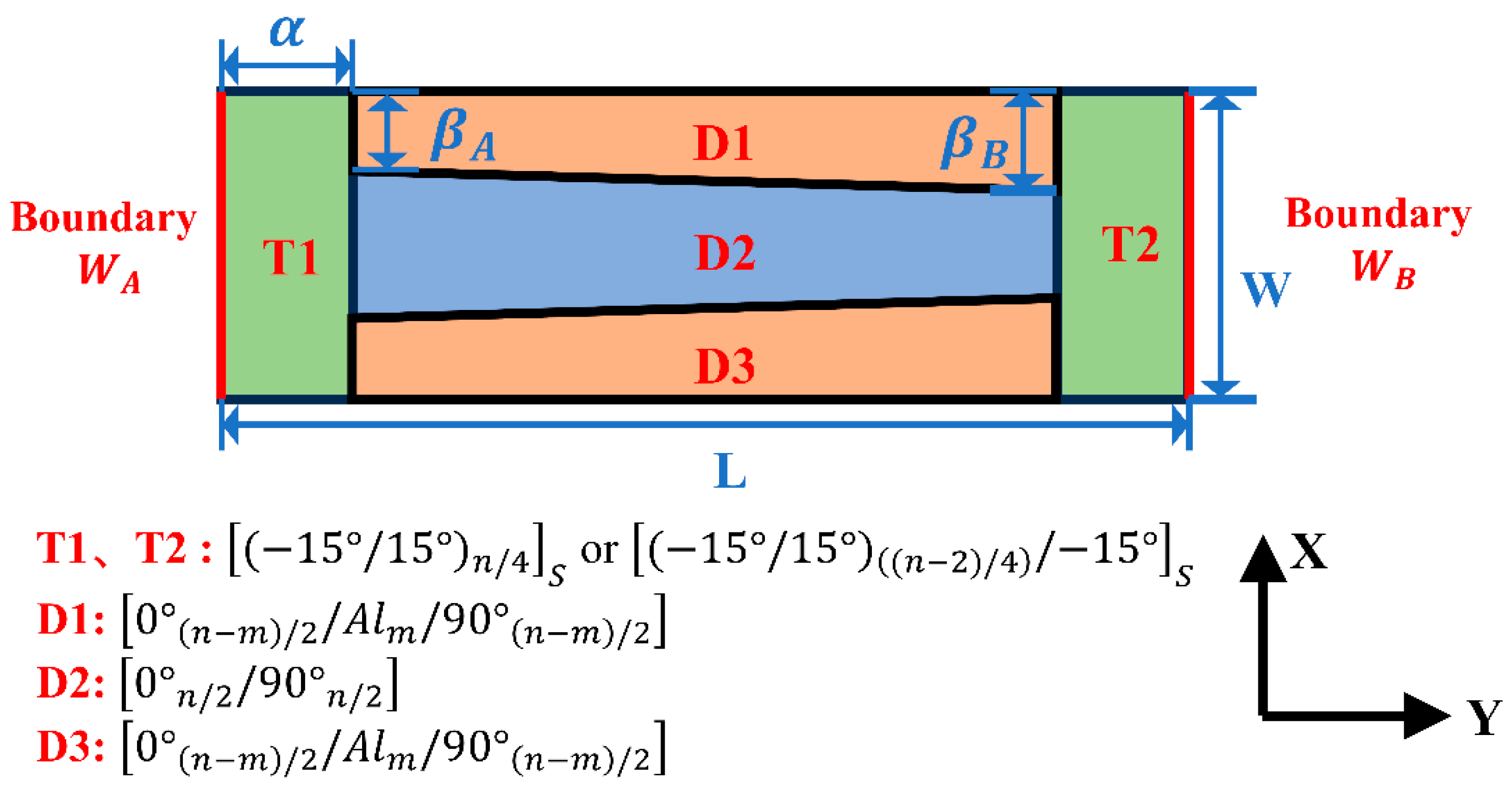
2.1. Structural Design of Variable-Stiffness Bistable Composite Laminate

The early-stage fabrication of bistable composite laminates predominantly employed non-metallic material systems. Subsequent research has demonstrated that incorporating metal layers can enhance structural deformation capability. Based on this, this study proposes a variable-stiffness design method for the bistable composite laminate deformation element, achieving active control of curvature distribution by changing the distribution of metal layers.
The structural partition and layering form of the rectangular composite laminate designed in this study are illustrated in Figure 1. The structure consists of two lateral transition elements and a central deformation element. Two transition elements (T1 and T2) adopt monostable symmetric layups to mitigate the influence of the boundary constraint on bistable characteristics. Let n denote the total number of composite plies (n ≥ 4). The layering forms are determined as follows:
[ ( 15 ° / 15 ° ) n / 4 ] s   , when   n / 2   is   even [ ( 15 ° / 15 ° ) ( ( n 2 ) / 4 ) / 15 ° ] s   , when   n / 2   is   odd
The bistable deformation element D is subdivided into three parts (D1–D3). Metal (aluminum) layers are incorporated in trapezoidal parts D1 and D3. Giving the number of metal layers as m, the layering forms can be represented as
[ 0 ° ( n m ) / 2 / A l m / 90 ° ( n m ) / 2 ] ,   for   D 1   D 3 [ 0 ° n / 2 / 90 ° n / 2 ] ,   for   D 2
The short symmetric edges of the left and right sides of the laminates are named boundary W A and boundary W B , respectively. During physical model fabrication, the fibers between the transition element T and the deformation element D overlap locally to ensure structural connection strength and deformation compatibility requirements. By adjusting the distribution of the metal layer in the deformation element, the curvature distribution and out-of-plane deformation can be controlled, conducive to improving the stiffness of the laminate. Key geometric parameters include the following: the short edge length is W; the long edge length is L; the proportion of the short side of the transition element to the long edge length of the laminate is α; the near boundary is W A ; the proportion of the edge length of the metal layer to the short edge length of the laminate is β A ; and the corresponding proportion near boundary  W B  is  β B .

2.2. Physical Model Fabrication and Analysis

M40J-7901 carbon fiber prepreg (Weihai Guangwei Group Co., Ltd., Weihai, China) and aluminum sheets were used to fabricate laminates in this study, and the material parameters are listed in Table 1 and Table 2. The samples under free-boundary conditions were obtained as follows: after designed cutting and layup, the laminates were cured under 0.7 MPa pressure at 125 °C for 2 h, followed by natural cooling. Three sets of specimens (parameters listed in Table 3) were fabricated, and the stable configurations of the physical model under free-boundary conditions are illustrated in Figure 2.
By comparing Figure 2a,b, it can be found that incorporating metal layers significantly enhances the overall deformation capability of the laminate in its initial stable configuration. Furthermore, Figure 2c shows that by adjusting the metal layer distribution parameters β A and β B , localized curvature can be directionally regulated. Increasing the parameter β A leads to a marked increase in curvature within the corresponding region, validating the critical role of metal layer distribution in governing bistable deformation behavior. Although the effect of metal layout adjustment on the control of out-of-plane deformation in the second stable configuration is relatively limited, the curvature distribution control characteristics observed in the initial stable configuration remain valuable for engineering applications.

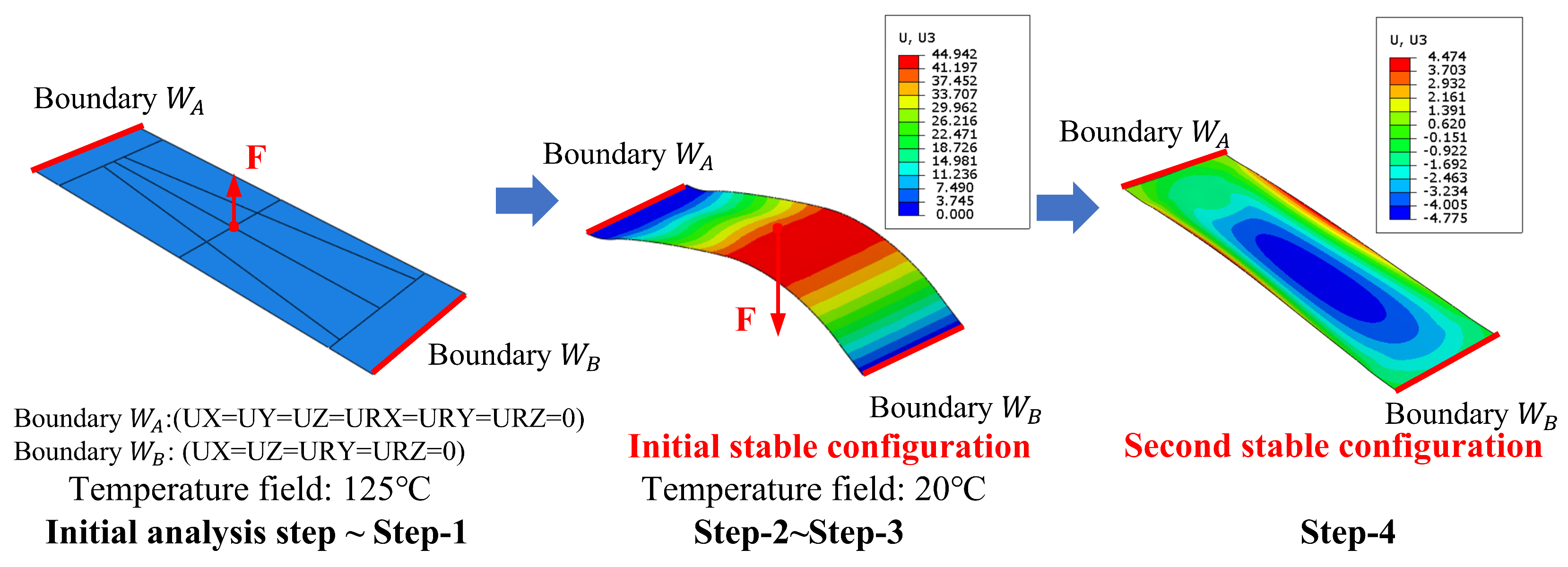
2.3. Finite Element Modeling

The numerical simulation model under free-boundary conditions was established in ABAQUS v.2021, with S4R elements used for meshing. Due to the significant out-of-plane displacements exhibited by composite laminates during deformation, it was necessary to consider geometric nonlinear effects by activating the Nlgeom option. An adaptive stabilization algorithm was used to enhance computational convergence. This method automatically regulated damping coefficients to achieve optimal equilibrium between numerical stability and solution accuracy. The simulation procedure comprised three steps:
(a) Initial analysis step: Apply fixed constraints at the laminate midpoint and set the temperature field to 125 °C;
(b) Step-1: Apply perturbation forces perpendicular to the laminate at its four vertices;
(c) Step-2: Remove the perturbation forces and set the temperature to 20 °C.
Through the above steps, the initial stable configuration of the laminate was obtained. The second stable configuration of the laminates was obtained by applying the reverse direction driving load. The finite element simulation process under free-boundary conditions is shown in Figure 3.
In practical applications, complex boundary constraints can affect the out-of-plane deformation effect of laminates. To address this challenge, this study utilized the high thermal expansion coefficient characteristics of metal materials and adjusted the area ratio of the metal layer near the constraint end to increase thermal deformation and compensate for the suppression effect of boundary constraints. When opposite edges of the laminate are subjected to different constraints, gradient stiffness allocation can be achieved through the differential design of metal-reinforced regions on both sides, balancing deformation disparities caused by uneven constraints. This distributed metal modulation strategy offered a novel approach for optimizing the deformation uniformity of laminates under complex constraint conditions, significantly enhancing structural adaptability to diverse boundary scenarios. In this study, distinct boundary constraints (fixed and hinged boundaries) were applied to opposite edges of the laminate to simulate actual application conditions. The numerical simulation proceeded as follows:
(a) Initial analysis step: Apply complex constraints and set the temperature field to 125 °C;
Boundary  W A : Fully fixed support (UX = UY = UZ = URX = URY = URZ = 0).
Boundary W B : Mixed constraints (UX = UZ = URY = URZ = 0), specifically retaining URX rotational freedom and UY axial freedom to mimic the semi-rigid characteristics of hinge connections.
(b) Step-1: Apply perturbation forces perpendicular to the laminate at its midpoint;
(c) Step-2: Remove the perturbation forces and set the temperature to 20 °C.
Following the above steps, the initial stable configuration of the laminate was obtained. The second stable configuration of the laminates was obtained by applying the reverse direction driving load. The finite element simulation process and second stable configurations of the bistable laminate under different constraints on two opposite edges are shown in Figure 4.

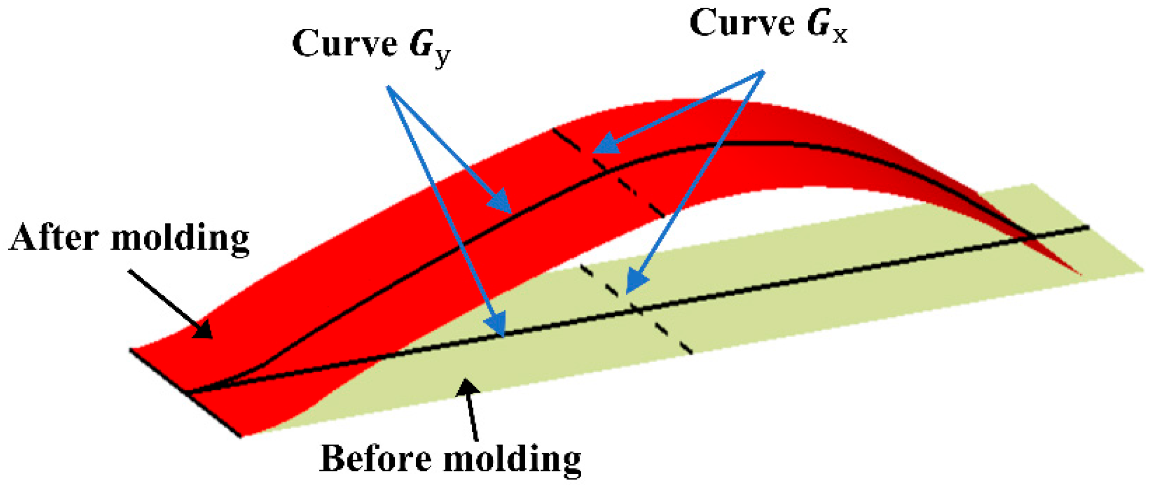
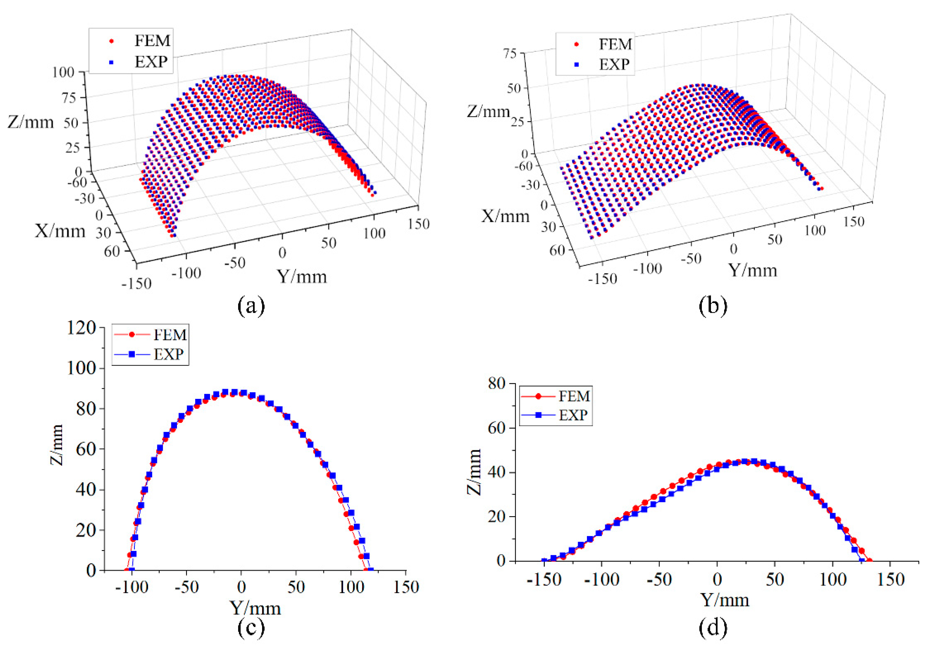
2.4. Initial Stable Configuration Comparison Between Finite Element and Physical Models

To validate the accuracy of the finite element model, the surface shape data of Sample 3 were obtained through a three-dimensional optical scanning system under free-boundary conditions and different constraints on two opposite edges (scanning experiment, as shown in Figure 5).
The mid-section line of the laminate parallel to the X-axis was defined as curve G x , while the mid-section line of the laminate parallel to the Y-axis was defined as curve G y . Their specific locations are shown in Figure 6. Deviation analysis was conducted between the experimental result and the numerical simulation result. Figure 7a displays the initial stable configurations of the finite element and physical models under free-boundary conditions, while Figure 7b compares their initial configurations under the different boundary constraints of two opposite edges. The results demonstrate high consistency in out-of-plane deformation trends between finite element and physical models under both conditions.
The out-of-plane displacement (Z-direction) of the curve G y was analyzed, as shown in Figure 7c,d. The maximum relative errors between the out-of-plane displacement of the physical model and finite element model were 9.02% (free-boundary conditions) and 12.52% (different boundary constraints), both within acceptable tolerance ranges. The above analysis structure proves the effectiveness of using numerical simulation to analyze the deformation behavior of laminates.

3. Analysis of Factors Influencing the Deformation Performances of Variable-Stiffness Bistable Laminates

To investigate the influence of laminate parameters on deformation performance under different boundary constraints, this section employed a finite element simulation model to analyze the controlling effects of the structural geometric parameters (W, L, α), distribution of metal layers ( β A , β B ), and layup ratios (m/n) on the bistable deformation characteristics. This study reveals the relationships between key parameters and deformation modes. The adjustable ranges of geometric parameters are set as follows: width W (80–100 mm), length L (260–300 mm), transition element edge proportion α (5–15%), and metal layer edge proportions β A   (10–40%) and β B   (10–40%). The analysis focuses on out-of-plane displacements and curvature distributions in two stable configurations.

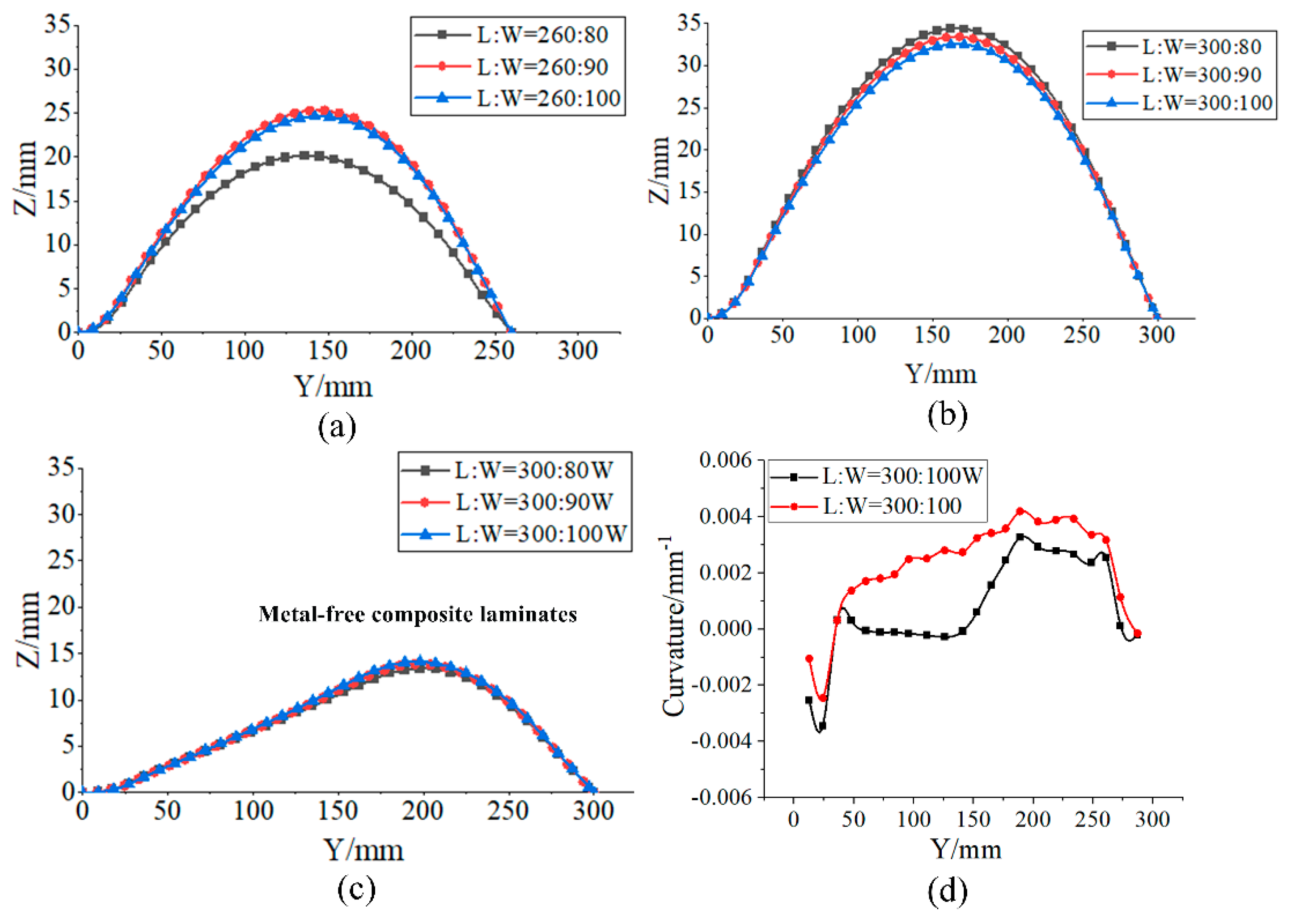
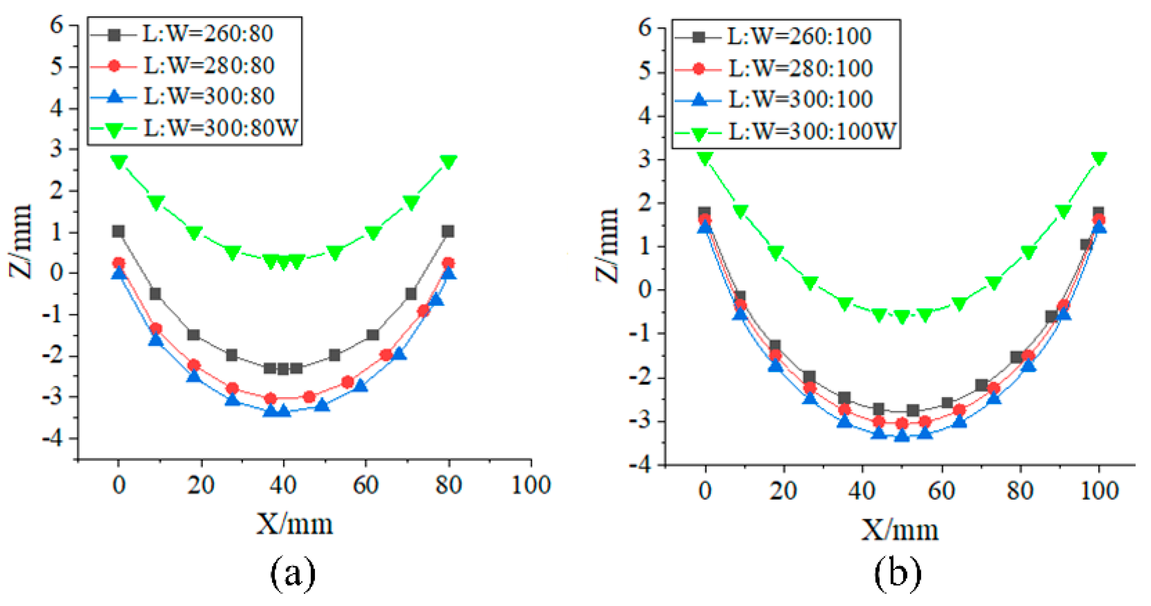
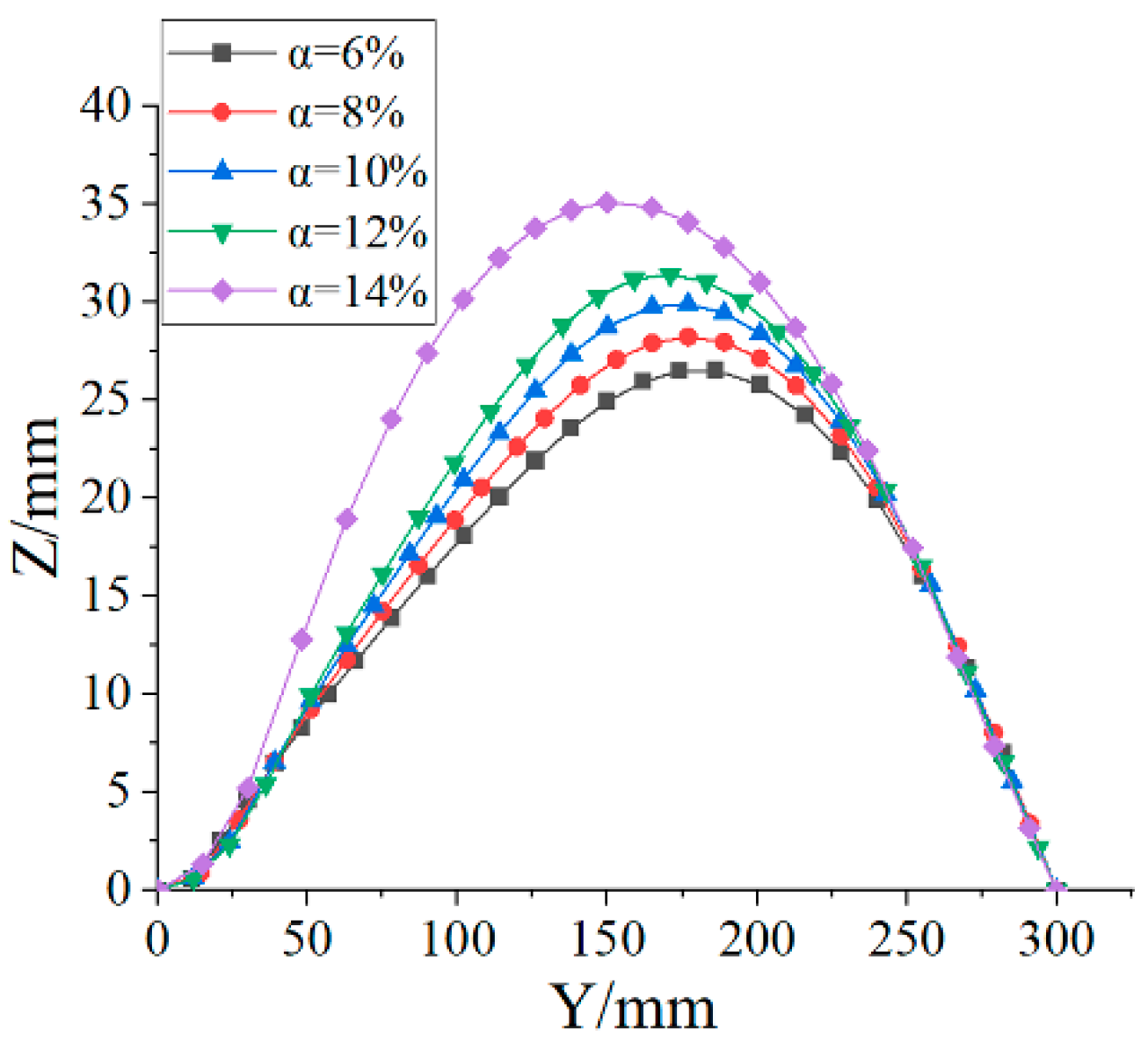
3.1. Influence of the Aspect Ratio on the Deformation Performances of Bistable Laminates

To investigate the influence of the aspect ratio on the deformation performance of laminates, the following parameters were selected: total layers n = 6; metal layers m = 2; metal layer edge proportions β A = β B = 20%; transition element edge proportion α = 10%. Figure 8 illustrates the out-of-plane displacement characteristics of the curve G y of laminates with varying aspect ratios in their initial stable configurations. The introduction of metallic materials in laminates creates contradictory mechanisms in the thermo-mechanical coupling effect. On one hand, as shown in Figure 8b,c, the addition of metal plies enhances structural deformation due to significant residual thermal stresses generated during curing from their higher thermal expansion coefficients. On the other hand, the increased local stiffness from metallic plies tends to suppress deformation development. Figure 8b demonstrates that for structures with higher aspect ratios, the stiffness inhibition effect dominates as the metal ply area proportion increases, leading to a decrease in out-of-plane deformation with increasing width. However, Figure 8a reveals that for structures with lower aspect ratios, the limited distribution area of metal plies allows the thermally driven stress effect to overcome the stiffness constraint, resulting in increased out-of-plane deformation with width expansion. This deformation trend matches that observed in the laminates without metal layers.
Furthermore, it can be observed that in laminates without metal layers, due to the fully fixed constraints at boundary W A , the adjacent region exhibits a low curvature transitional state. The peak point of out-of-plane displacement shifts toward boundary W B , resulting in weakened bistable characteristics. After adding metal layers, under the synergistic effect of thermal residual stress and stiffness gradient, the peak point of the out-of-plane displacement of the laminated plate moves towards the center region of the structure, the displacement amplitude significantly increases, and the symmetry of the displacement curve significantly improves. Figure 8d compares the curvature distributions of laminated plates with and without metal layers, revealing that the curvature distribution uniformity of laminates with added metal layers is better than that of laminates without metal layers.
The deformation patterns of laminates with varying aspect ratios in the second stable state, as illustrated in Figure 9, are characterized by a distinct negative bending (reverse curvature along the Z-axis) in the central region, evidenced by the out-of-plane displacement distribution of curve G x . Incorporating metallic materials significantly amplifies the bending curvature in this region. Furthermore, when the laminate width is fixed, an increase in length L (i.e., a higher aspect ratio) reduces the out-of-plane bending stiffness, leading to significant increases in both the maximum deformation magnitude and the curvature.

3.2. Influence of Metal Layer Edge Proportions on the Deformation Performances of Bistable Laminates

To investigate the influence of the metal layer edge proportions β A and β B on the deformation behavior of laminates, the following structural parameters are specified: total number of layers n = 6; metal layers m = 2; width W = 100 mm; length L = 300 mm.
As shown in Figure 10, the out-of-plane displacement of curve G x  of laminates is analyzed in the initial stable configuration with the varying parameters  β A  and β B . When either β A or β B independently increases, the peak point of the out-of-plane displacement shifts toward the corresponding boundary ( W A or W B ). However, due to the higher degree of freedom at boundary W B compared with boundary W A , the peak point of the out-of-plane displacement is closer to boundary W B . This indicates a significant coupling effect between geometric constraints and the asymmetric distribution of metal layup parameters.
Further investigation into the effects of the reverse configurations of β A and β B on the out-of-plane displacement of curve G y of laminates in the initial stable configuration (Figure 11) reveals that increasing β B is more effective than increasing β A for enhancing the overall deformation magnitude. At the same time, the larger the difference between β A and β B , the more significant the difference in the out-of-plane displacement of the laminates under the two layout conditions. As β A increases, although the total deformation of the laminated plate decreases, the symmetry of its out-of-plane deformation is significantly enhanced. This phenomenon arises because the metal layer provides localized stiffness compensation in the high-constraint region at boundary W A , creating a “rigid support” effect. This effect not only counteracts the deformation suppression caused by over-constraint but also improves the deformation compatibility, thereby balancing deformation deviations induced by differing boundary constraints. Ultimately, this optimizes the symmetric distribution of structural deformation.
The influence of metal layer distribution in the second stable configuration deformation behavior of laminates is investigated through the comparison of curvature distributions at three characteristic locations (as shown in Figure 12): the boundary of the deformation element near boundary  W A (Curve 1); curve G x  (Curve 2); the boundary of the deformation element near boundary  W B  (Curve 3). The analysis shows that the curvature amplitude and variation range of curve G x (Curve 2) are significantly greater than those at the deformation element boundaries (Curves 1 and 3). Moreover, the stress concentration effect caused by the large difference in the thermal expansion coefficient at the interface between metal and composite materials leads to a step change in curvature distribution. On the same laminate, the side with a higher proportion of metal layer boundaries has a larger curvature. Moreover, the larger the difference between β A and β B , the smaller the difference in the curvature distribution of curve G x between the two layout cases with inversely configured β A and β B . This is illustrated by Curve 2 in Figure 12b,c, where Curve 2 has a higher similarity in curvature (curve G x ), which is opposite to the out-of-plane displacement trend of the curve G y of the laminate in the initial stable configuration.

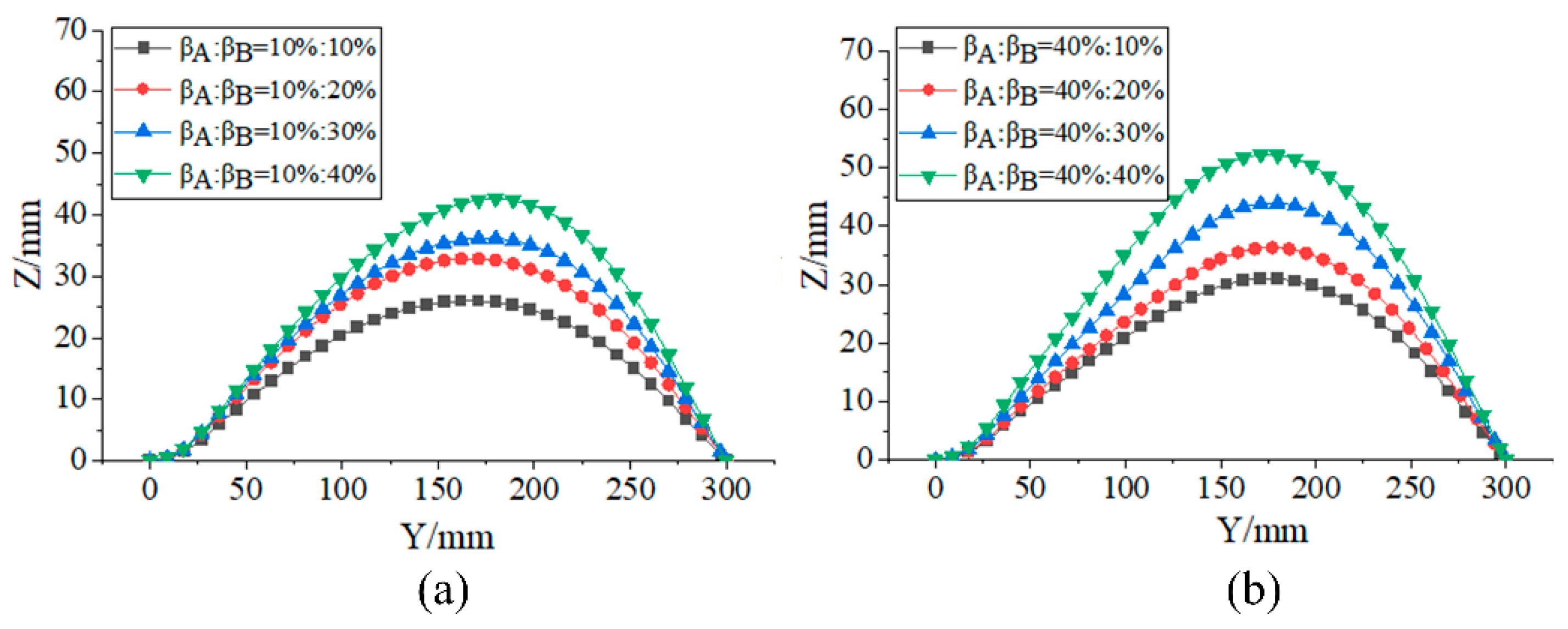
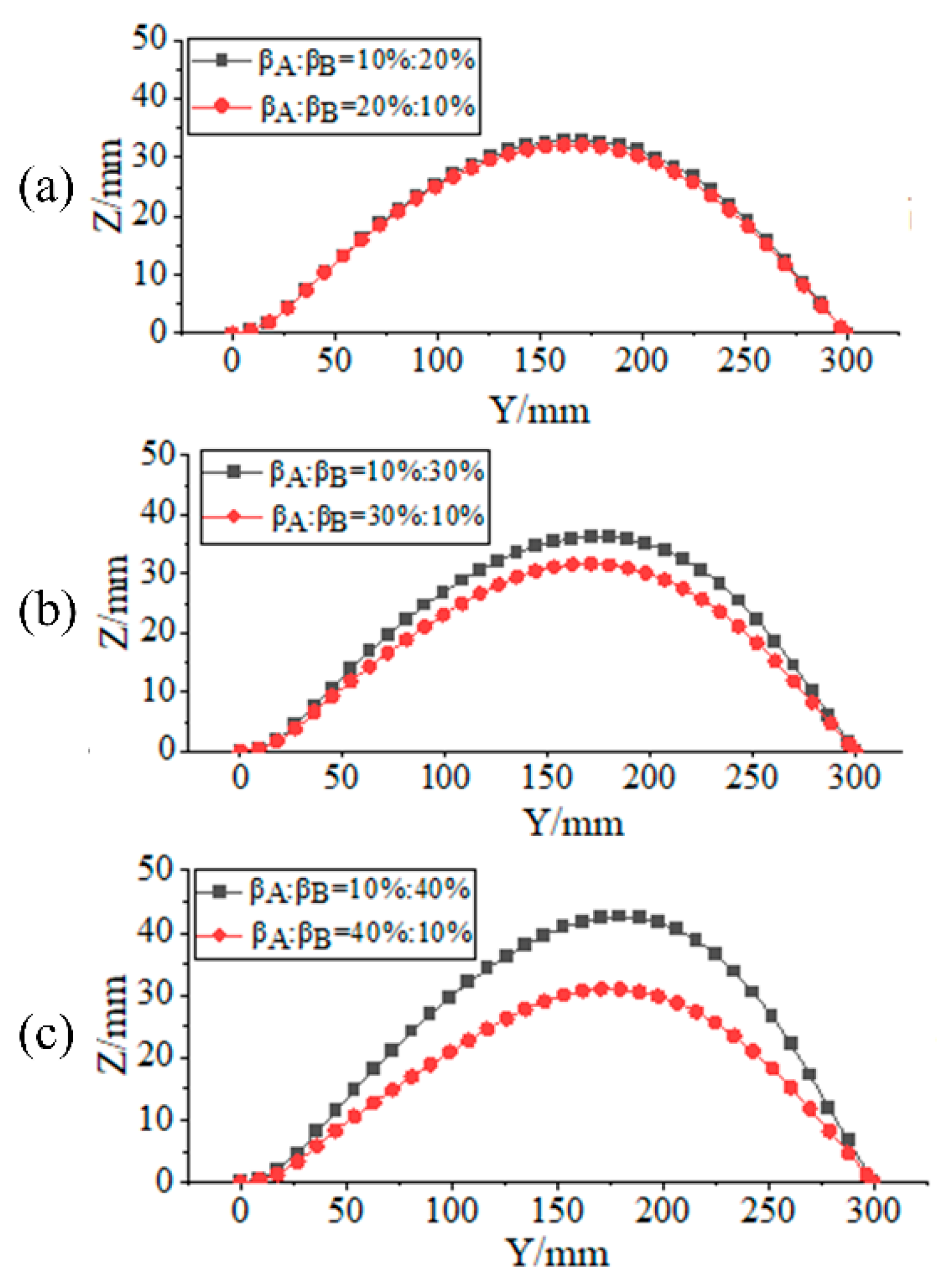
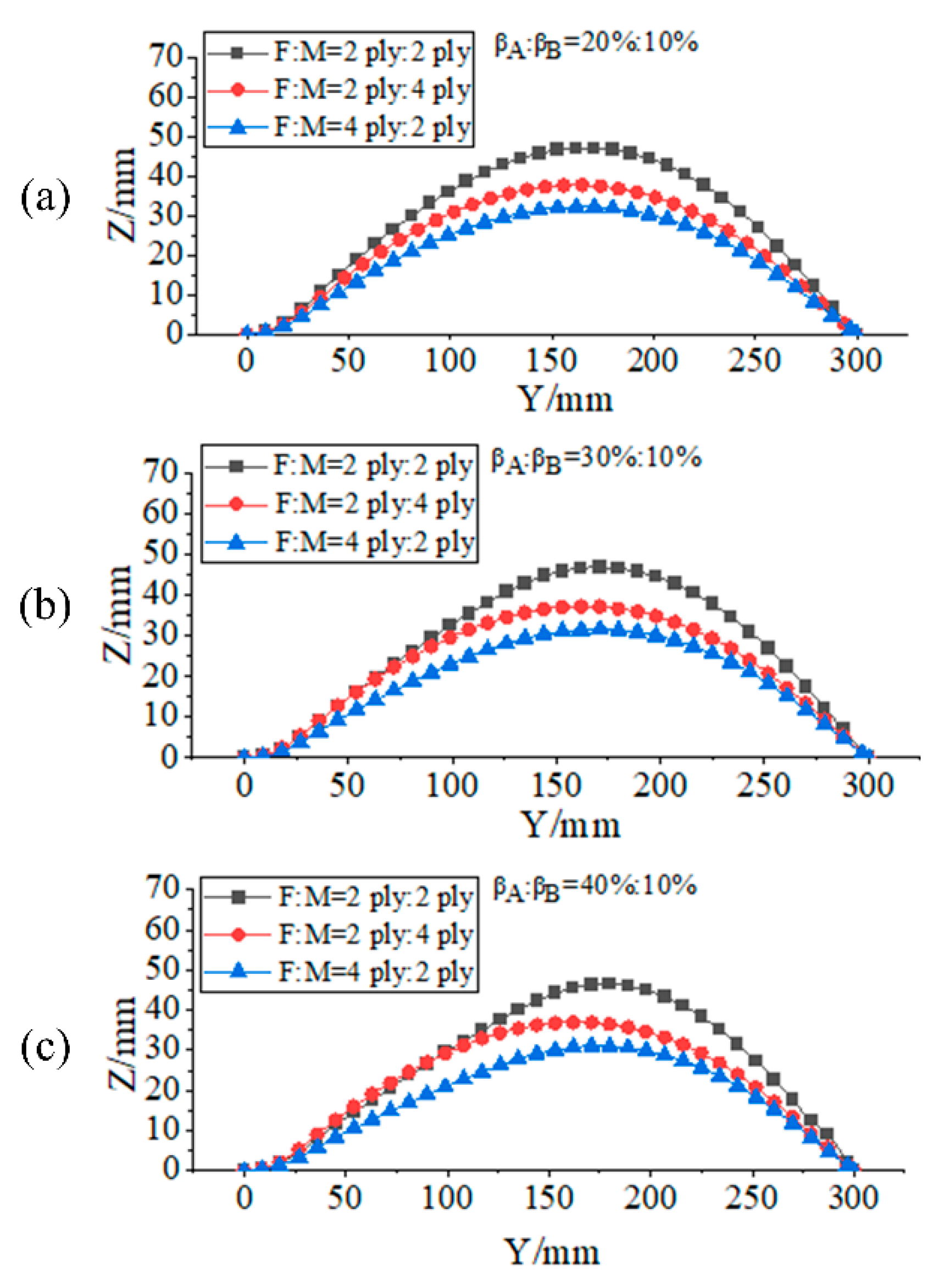
3.3. Influence of the Number of Layers and Layup Ratio of Two Materials on the Deformation Performances of Laminates

To investigate the impact of the number of layers and the ratio of two materials (carbon fiber composite and metal) on the deformation performances of laminates, the following parameters are selected: length L = 300 mm; width W = 100 mm; transition element edge proportion α = 10%; metal layer edge proportions β A > β B .
Figure 13 shows the out-of-plane displacement of curve G y  of laminates with different total number of layers and material layer ratios at the initial stable configuration. As the total number of layers n increases, the improvement of the overall stiffness of the structure reduces the out-of-plane displacement. The stiffness homogenization effect causes the peak point of the out-of-plane displacement of the laminate to shift towards curve G x , significantly improving the deformation bias phenomenon of the structure when subjected to different constraints on the opposite edges. The effectiveness of metal layers in amplifying structural deformation is governed by the coupling effects of the layup ratio (m/n) and the edge length proportion distribution ( β A , β B ). When the metal layer edge proportion is low, increasing the number of metal layers m enhances deformation due to the dominance of thermal residual stress. Conversely, when the metal layer edge proportion is high, increasing m weakens the deformation capacity, as the abrupt stiffness enhancement in metal-dominated regions suppresses deformation development. Notably, a metal layup ratio below 1:2 (e.g., composite-to-metal ratio of 2 ply:4 ply) results in the loss of bistable switching capability in laminates. This phenomenon indicates threshold competition between the residual stress advantages and stiffness suppression effects induced by the metal layer. To achieve targeted deformation control, synergistically optimizing the layup ratios and edge length proportion distributions of the metal layer is essential to balance this competing mechanism.
A comparative analysis of curvature distribution along the x-axis is conducted for laminates with distinct material layup ratios (composite-to-metal ratios of 2 ply:2 ply and 4 ply:2 ply) in the second stable configuration, with analytical results presented in Figure 14. When the total number of plies increases and the number of metal layers is fixed, the curvature of the deformation element boundary (curve 1) near the fully constrained end (boundary W A ) changes significantly, while the curvature distribution of curve G x (curve 2) changes relatively little. To alleviate the curvature attenuation phenomenon in various regions of laminates caused by an increase in the number of layers, the proportion of the metal layer area can be appropriately increased (increase β A and β B ), and the high thermal residual stress characteristics of metal materials can be utilized to partially counteract the stiffness-strengthening effect, thereby achieving controllable maintenance of curvature amplitude.

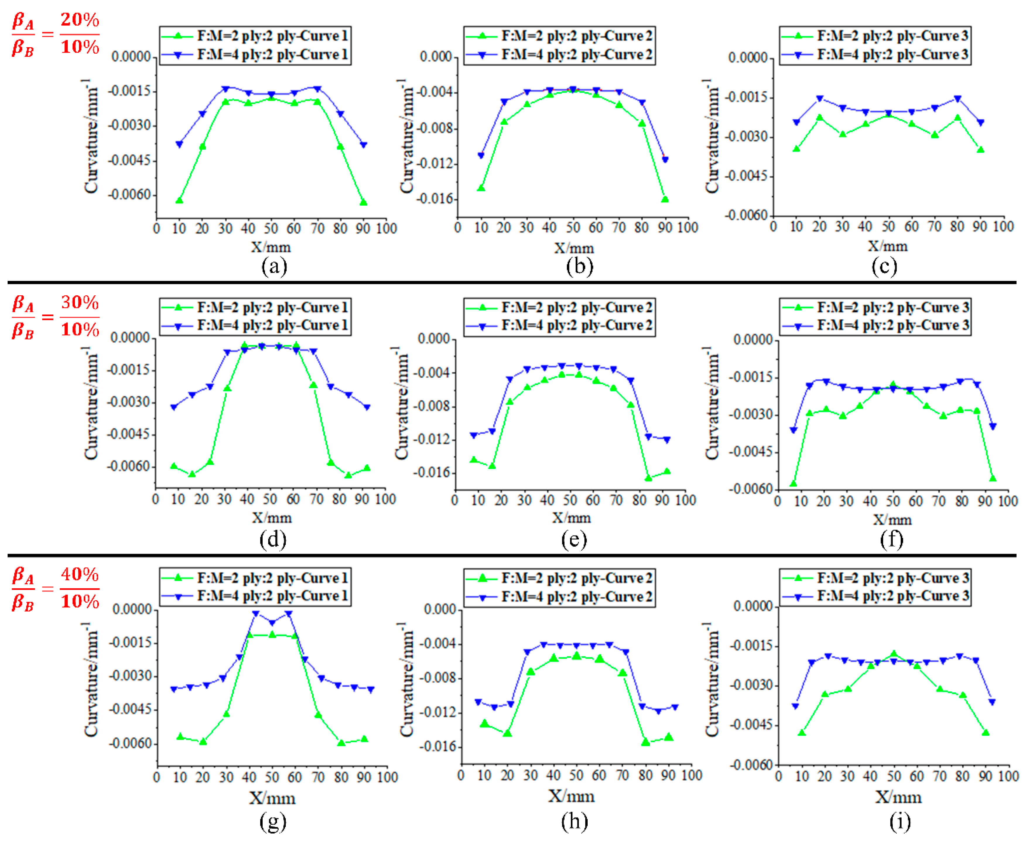
3.4. Influence of Transition Element Edge Proportion on Deformation Performances of Laminates

For a laminate with β A / β B ratio = 40%:10%, regions with higher metal area proportions exhibit local curvature-strengthening characteristics under free-boundary conditions due to the accumulation of thermal residual stresses. However, in the condition where opposite edges of the laminate are subjected to differential constraints, the boundary effect at the strongly constrained end (boundary W A : fully fixed constraint) suppresses deformation development in this region, causing it to degenerate into a low-curvature transitional state. Concurrently, the peak point of out-of-plane displacement shifts towards the region with weaker constraints (boundary W B : hinged connection). The disparity in deformation characteristics between laminates under free-boundary and constrained-boundary conditions demonstrates that relying solely on metal layer optimization cannot fully eliminate the effects of boundary constraints. Therefore, it is necessary to adjust the proportion of the transition element edge to control the coupling intensity between constraint boundaries and the deformation element.
The influence of the transition element edge proportion on the out-of-plane displacement of curve G y in the initial stable configuration is analyzed, as shown in Figure 15. The results show that increasing the proportion of the transition element edge can effectively weaken the boundary constraint effect and make the deformation characteristics of the constrained structure gradually converge to the free-state behavior; then, curvature in previously suppressed regions recovers significantly, the peak point of out-of-plane displacement shifts toward the structural center, and overall deformation symmetry improves. Through the synergistic optimization of metal ply distribution and transition element edge proportion parameters, a dual-control mechanism combining “boundary decoupling” and “thermal stress redistribution” is established. This integrated approach enables effective deformation regulation under complex constraint conditions.

3.5. Analysis and Summary of Influencing Factors on Laminate Deformation

The deformation performances of laminates are governed through multifactorial coupling interactions among the aspect ratio, metal layer parameters, and boundary constraints. This study reveals that introducing metal layers regulates deformation through the competing mechanisms of thermal residual stress and stiffness suppression: when the aspect ratio of the laminate is large, an increase in metal layer area enhances stiffness suppression, leading to reduced out-of-plane deformation with increasing width; in contrast, for smaller aspect ratios, the dominance of thermal stress causes the deformation behavior to approach those of non-metallic composite structures, that is, the out-of-plane deformation increases with the increase in width. By coordinating thermal stress and stiffness gradients through metal layer design, the symmetry of out-of-plane displacement and the uniformity of curvature distribution in laminates can be significantly improved.
Additionally, the deformation characteristics of laminates are nonlinearly coupled with the total number of plies and the ratio of metal layers. Excessive total ply counts or high metal layer ratios can suppress deformation and eliminate bistable behavior. However, rational ply selection can effectively mitigate deformation bias caused by different boundary constraints while maintaining bistable switching capability. The design of transition element weakens boundary constraint interference and synergizes with metal layer parameters to achieve dual regulation of “boundary decoupling” and “thermal stress redistribution”, driving the deformation of constrained structures toward free-state behavior. This study demonstrates that synergistically optimizing the metal layer ratio, edge proportion distribution, and transition element parameters enables the directional control of laminate deformation under complex operating conditions.

4. Research on Variable-Camber Wing Design Based on Variable-Stiffness Bistable Laminates

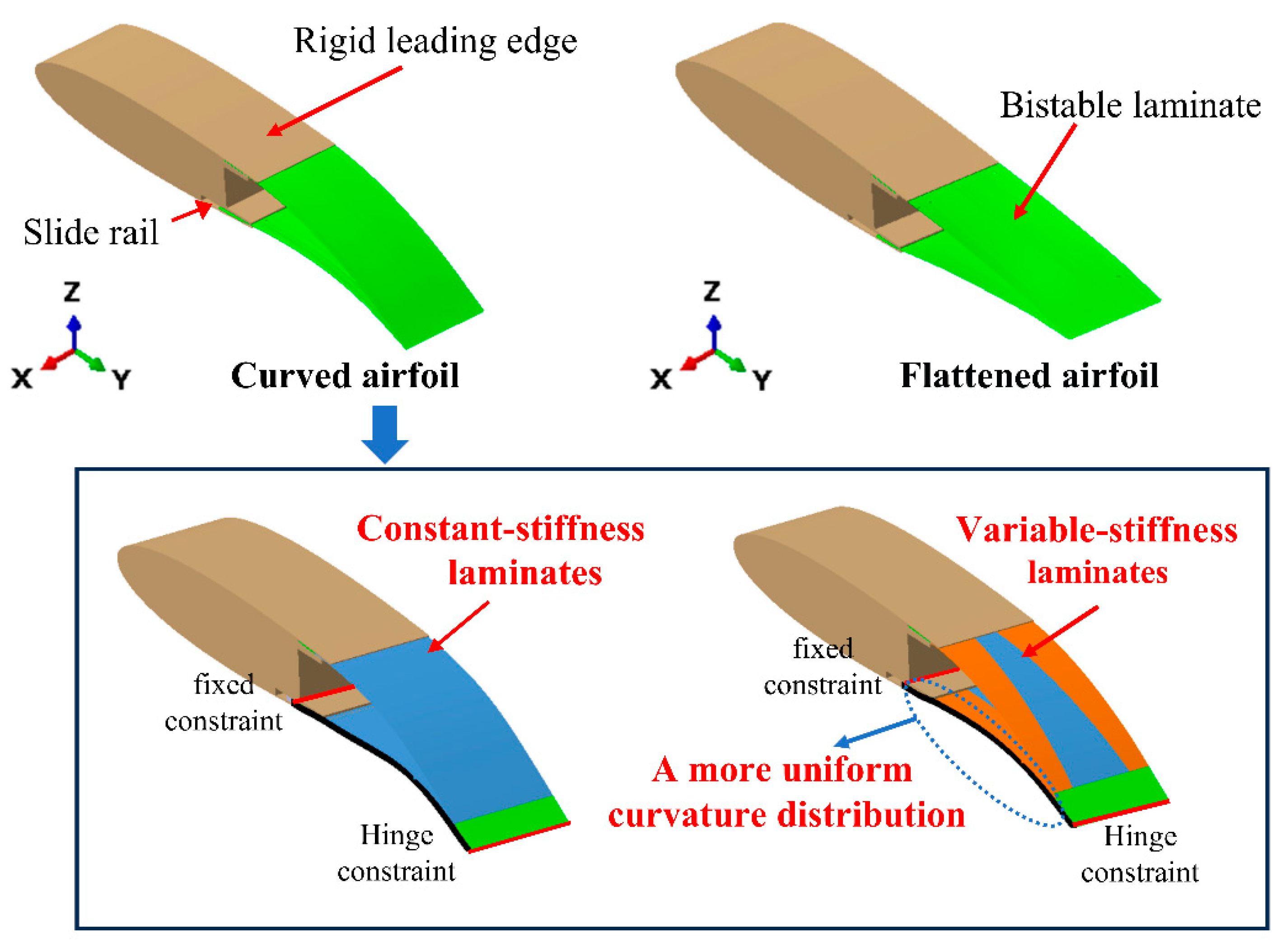
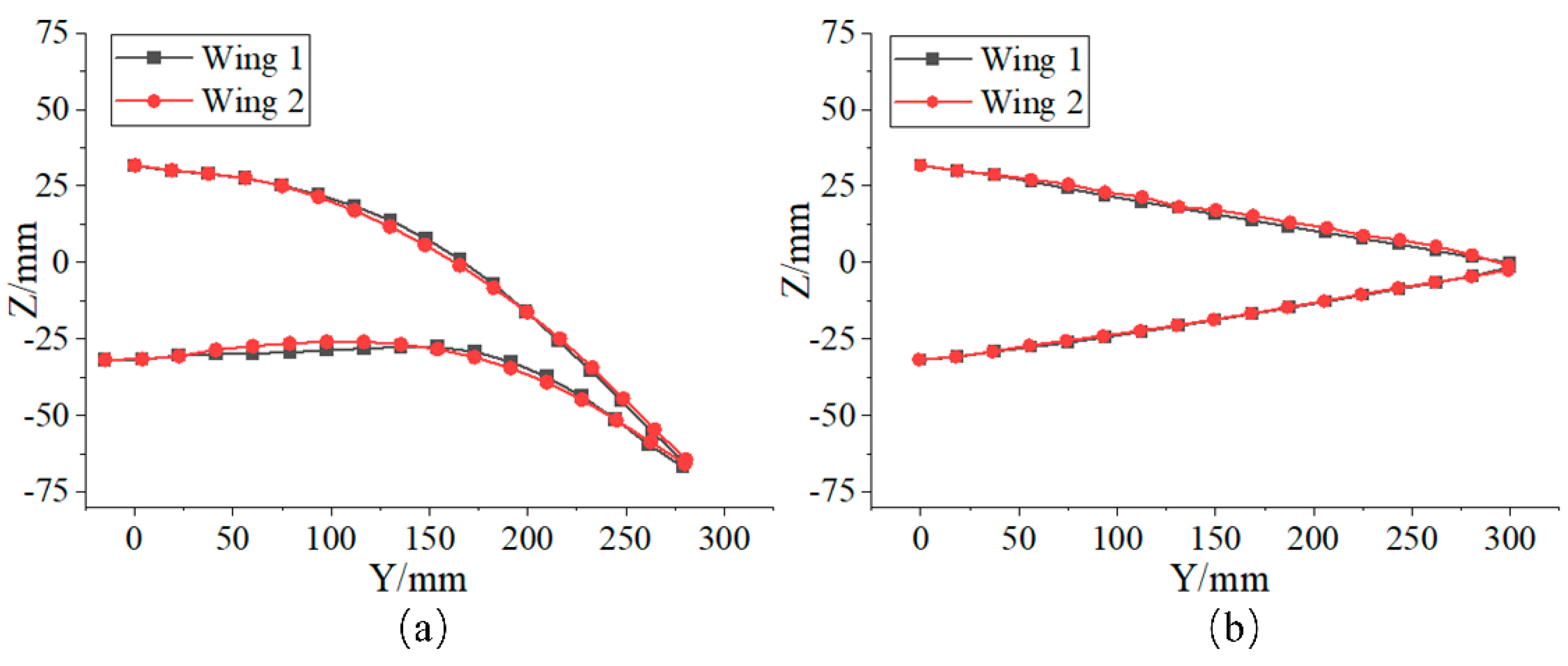
4.1. Conceptual Design of Variable-Camber Wings

In this study, the adaptive bistable variable bending wing is designed based on the NACA0012 airfoil (chord length 600 mm, trailing edge 50%). The wing structure is divided into two segments: the leading edge section from the leading edge to 50% chord length is a rigid structure, while the trailing edge variable-camber section incorporates a bistable laminated skin. Boundary W A of the laminated skin is fixed to the rigid leading edge, and boundary W B employs hinges to synchronize the deformation between the upper and lower skins, with all constraint conditions consistent with the previous analysis. The lower wing surface is driven to slide through the slide rail transmission mechanism to achieve the switching of the laminate between the two stable configurations, that is, to realize the conversion of the two airfoils of the wing. The initial stable configuration of laminate corresponds to a cambered airfoil configuration (increasing lift), while the second stable configuration corresponds to a flattened airfoil (reducing cruising drag); both configurations are illustrated in Figure 16.

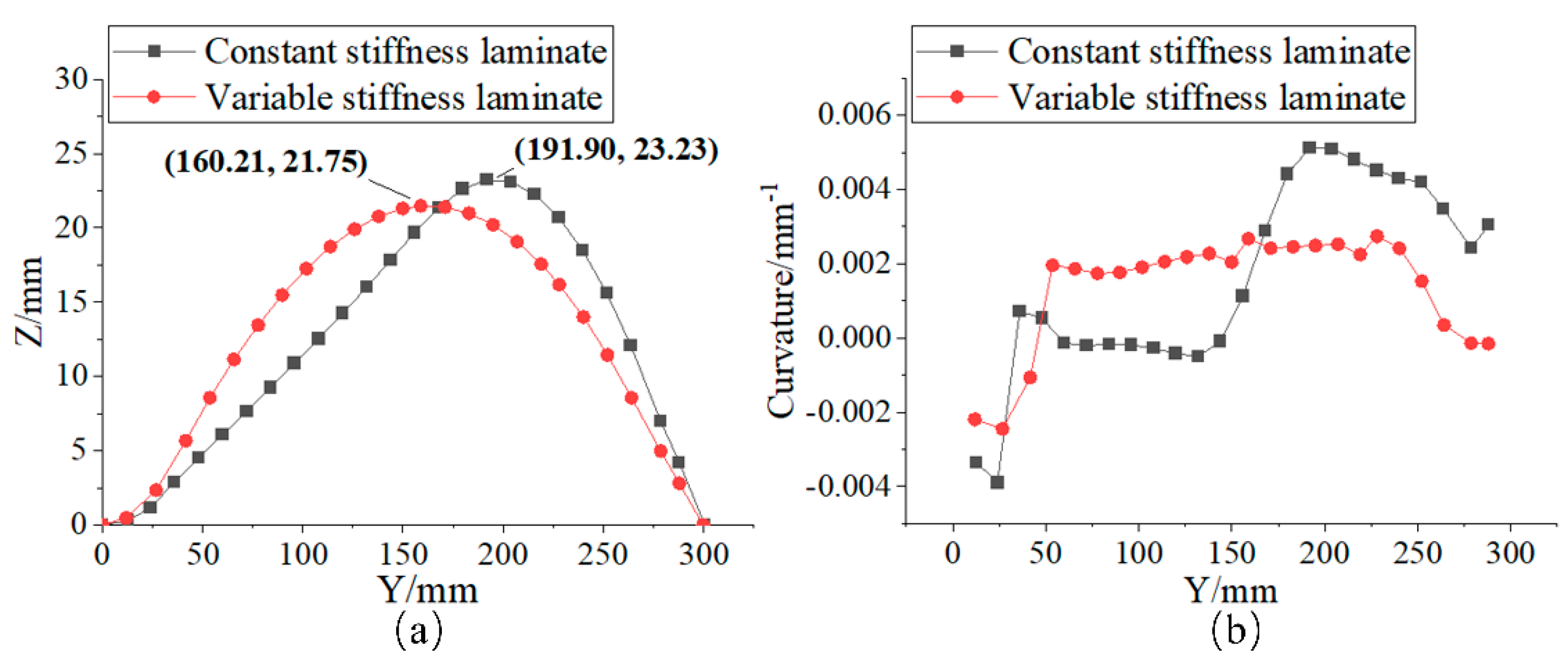
4.2. Comparison of Deformation Properties of Constant-Stiffness and Variable-Stiffness Laminates

This section investigates the impact of constant-stiffness and variable-stiffness laminates on the aerodynamic performance of the wing, analyzing the necessity of adjusting the trailing-edge curvature distribution to improve aerodynamic efficiency. Since the curvature of the laminate along the X-axis in the second stable configuration is small and has minimal effect on the aerodynamic performance, this study focuses on the deformation characteristics of the laminate in the initial stable configuration. Based on the requirements of load-bearing capacity and bistable characteristics, the total number of composite layers is set to 10. The above analysis shows that an excessive total number of layers or a high ratio of metal layers can stiffen the structure, suppress out-of-plane deformation, and impair bistable switching capability. Therefore, for configurations with a large number of layers, the ratio of composite to metal layers is optimized to 4:1 (carbon fiber composite/metal = 8 ply:2 ply) by balancing the relationship between laminate stiffness and deformation.
The design parameters for constant-stiffness and variable-stiffness laminates are listed in Table 4. The constant-stiffness laminate uses a uniform metal layer distribution ( β A = β B = 50%). The variable-stiffness laminate employs a graded metal layer design: the strong constraint end (boundary W A ) has a metal layer edge proportion β A = 40%, utilizing the high thermal expansion characteristics of metal to enhance local thermal residual stress and improve curvature amplitude and deformation capacity in this region. The proportion of metal layup edge length at the weakly constrained end (boundary W B ) is β B = 21%. Under the premise of ensuring the deformation of the laminate foundation, the stiffness suppression effect is weakened by reducing the proportion of metal distribution, promoting the displacement of deformation energy towards the highly constrained end and optimizing the curvature distribution. The proportion of the transition element is α = 13%, which not only alleviates the interference of boundary constraints on the deformation element but also avoids excessively weakening the structural load-bearing stiffness caused by excessively long transition segments. The optimization process for parameter selection for variable-stiffness laminates mentioned above will not be further introduced in this article.
Analysis shows that when β A and β B are similar or equal, the thermal mechanical coupling effect is asymmetrically distributed on the laminate under different boundary constraints applied to two opposite edges. This imbalance causes the peak point of the out-of-plane displacement in the initial stable configuration to shift toward boundary W B . As shown in Table 5, the maximum out-of-plane displacement of the constant-stiffness laminate is 23.23 mm, and the peak point of the out-of-plane displacement is 41.90 mm away from the curve G x in the Y-axis direction. In contrast, the maximum out-of-plane displacement of the variable-stiffness laminate using the metal laminate optimization design is reduced to 21.75 mm (6.37% less than the constant-stiffness design). In addition, in the Y-axis direction, the peak point of out-of-plane displacement of the variable-stiffness laminate is 10.21 mm away from curve G x , and the positional symmetry is improved by 75.63%. As shown in Figure 17a, the variable-stiffness laminate with metal-graded design demonstrates a marginally lower maximum out-of-plane displacement amplitude than the constant-stiffness counterpart, but the peak point of out-of-plane displacement shifts toward curve G x , effectively alleviating the deformation deviation. The curvature field in Figure 17b further reveals that the variable-stiffness design can reconstruct the distribution of thermal residual stress, achieving better continuous transition characteristics of bending curvature, significantly improving the deformation compatibility and structural symmetry.
The constant-stiffness laminate and variable-stiffness laminate are applied to the wings and named wing 1 and wing 2, respectively. The rear-edge cross-sections of the two airfoil configurations corresponding to each wing are shown in Figure 18. When the laminates are in the initial stable configuration (cambered airfoil), the lower airfoil area near the fixed constraint end of the wing 1 presents a low curvature transition feature due to local stiffness enhancement. With stiffness gradient optimization, the lower airfoil of wing 2 can achieve a better transition in the constrained region and show a more uniform curvature distribution. When the laminate is in the second stable configuration (flattened airfoil), the two wings are similar in appearance and basically return to the original symmetrical airfoil profile. Under the cambered airfoil configuration, the maximum trailing edge deformation of wing 1 is 66.16 mm, while that of wing 2 is 65.14 mm. Although wing 2 exhibits a slightly smaller deflection displacement, its bending curvature demonstrates a more continuous distribution in the chordwise direction. The finite element models of two wings with two distinct airfoils are shown in Figure 19.

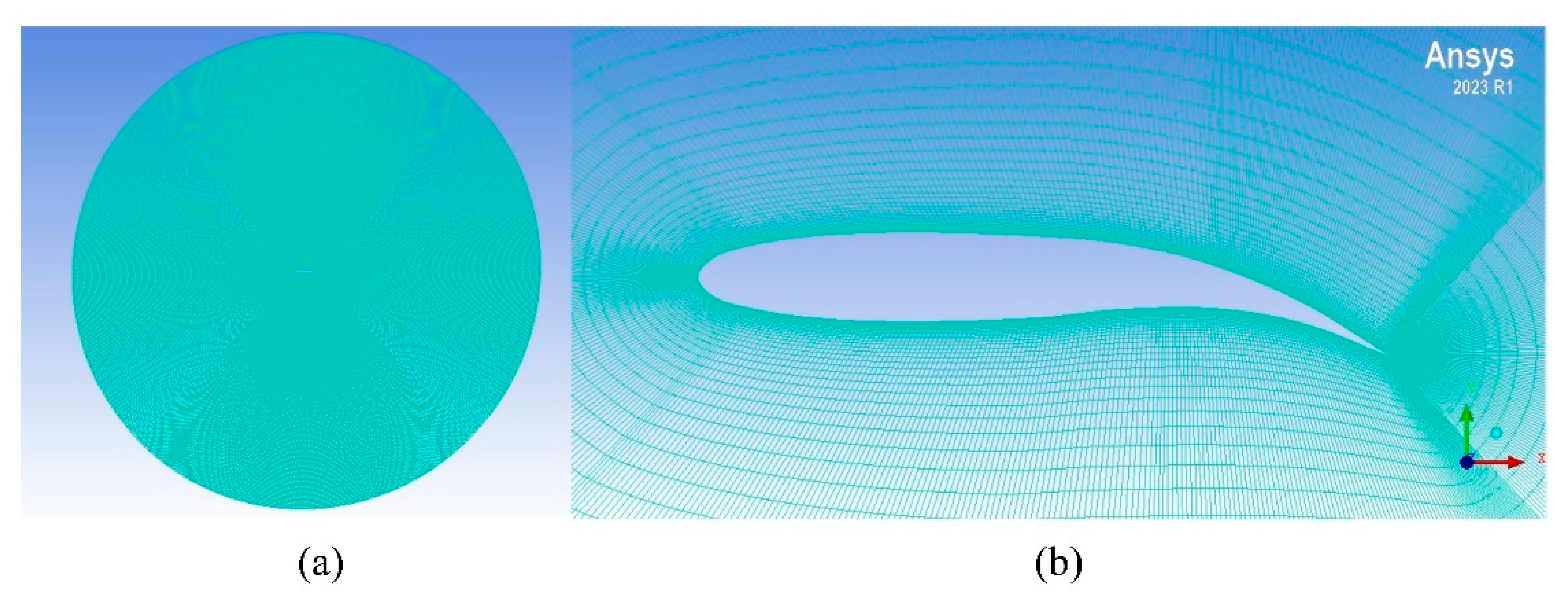
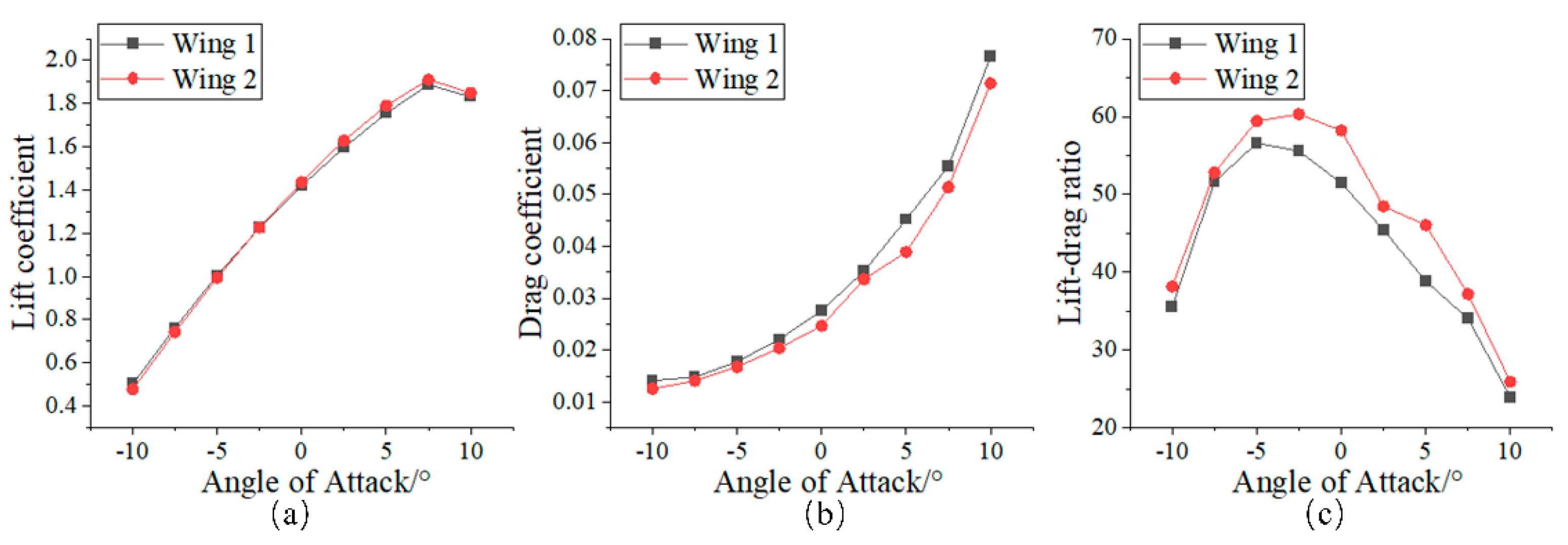
4.3. Aerodynamic Performance Analysis of Variable-CAMBER Wings

This section evaluates the aerodynamic performance of the wing. The specific simulation analysis steps are as follows:
(1) Extract the deformed contour of the wing in ABAQUS v.2021.
(2) Import the wing contour curve into ICEM CFD v.2023 R1 and perform O-grid structured 2D meshing. The characteristic length is defined by the airfoil chord length D, with a computational domain radius R = 10D, ensuring that far-field boundary effects are negligible on the aerodynamic flow around the airfoil. Refinement is applied to the area around the wing, with the first layer grid of the boundary layer set to y + = 1 . Considering both computational accuracy and efficiency, the total number of grid elements is 147,408. The airfoil computational domain and grid refinement zones are shown in Figure 20.
(3) Import the meshed 2D model into Fluent v.2023 R1. The Spalart–Allmaras turbulence model is selected. The inlet boundary condition is set as a velocity inlet with a magnitude of 0.2 Ma (68 m/s), the outlet as a pressure outlet, and the airfoil surface as a no-slip wall. The pressure–velocity coupling is solved using the SIMPLE algorithm until convergence is achieved. The flow field setup parameters are listed in Table 6.
As shown in Figure 21, the aerodynamic characteristics of the airfoil exhibit significant patterns with variations in the angle of attack. Due to their similar bending tendencies, both wings demonstrate fundamentally consistent lift coefficient variations: their lift coefficients increase with the angle of attack and undergo a stall-induced abrupt drop at 7.5°. In terms of drag characteristics, wing 2 significantly reduces its drag coefficient compared to wing 1 through optimized curvature gradient distribution at the trailing edge. Comprehensive analysis reveals that wing 2 achieves superior drag performance while maintaining lift levels comparable to wing 1, thereby improving the lift-to-drag ratio the angle-of-attack range of −10° to 10°. Notably, at a 2.5° angle of attack, the lift-to-drag ratio of wing 2 peaks at 63.4, representing a 14.15% enhancement over wing 1.
Figure 22 shows the aerodynamic performance comparison between the cambered airfoil and the flattened airfoil of wing 2. The bistable wing exhibits significant evolution in aerodynamic characteristics during configuration transition: For the cambered airfoil, both the lift coefficient and drag coefficient of the wing gradually increase with the angle of attack. In contrast, the flattened airfoil exhibits an increasing trend for lift coefficient with angle of attack, while the drag coefficient initially decreases and then increases. Regarding lift-to-drag ratio characteristics, the cambered airfoil demonstrates superior lift-to-drag ratio performance in the negative angle of attack regime, whereas the flattened airfoil achieves higher aerodynamic efficiency in positive angle of attack ranges. The research suggests that adaptive dynamic configuration adjustments based on flight conditions (cambered airfoil for high-load maneuvers and flattened airfoil for efficient cruising) can synergistically optimize flight performance and energy efficiency. This intelligent deformation mechanism sensitive to the aerodynamic environment expands the adaptability of the wing within different speed ranges.

5. Conclusions

In current research on integrating bistable laminates into wings, traditional designs utilize segmented configurations to adjust localized stiffness, thereby improving their embedment performance within rigid frames. However, each segmented region maintains constant stiffness properties. While such designs achieve fundamental deformation functionality, they may impair the uniformity of curvature distribution, thereby affecting the utilization efficiency of the structure. Furthermore, existing studies primarily optimize under single constraint conditions, failing to adequately address deformation requirements in scenarios involving complex hybrid boundary constraints. Therefore, this study proposes an innovative variable-stiffness bistable laminated plate design. By integrating the asymmetric distribution of metallic materials with integrated segmented configurations, this approach optimizes the continuity of curvature distribution in laminates under complex constraints. This study analyzes the coupled effects of geometric parameters, the proportion of metal layer edge length, and the number of layers on the deformation behavior of bistable laminates. It proves that metal layup can reconstruct the stiffness gradient field and thermal stress distribution, significantly improving the displacement symmetry and curvature uniformity of laminates under different constraint conditions on the opposite side. By collaboratively optimizing metal layup ratios, edge length distribution, and transition element edge proportion parameters, directional control of laminate deformation under complex boundary conditions can be achieved.
Building upon this foundation, this study further conducts a comparative investigation between variable-stiffness and constant-stiffness laminated plates in wing leading-edge structures. Aerodynamic performance analysis demonstrates that the wing combined with variable-stiffness laminates achieves full-angle-of-attack-domain improvement in lift-to-drag ratio characteristics due to enhanced trailing-edge camber and optimized curvature distribution in its curved configuration. Additionally, the aerodynamic response differences between the two airfoil types further reveal their potential for flight condition-adaptive control: the cambered airfoil adapts to high-lift demands, whereas the flattened airfoil suits efficient cruising. Dynamic switching between these configurations enables flight envelope expansion.
The novel variable-stiffness bistable laminate design proposed in this study breaks through the performance limitations of conventional laminates under different boundary constraints applied to two opposite edges, while also providing innovative references for engineering applications of smart morphing structures in multi-physics coupled operating conditions. Current limitations primarily lie in the insufficient consideration of the load-coupling effects of internal wing support structures and the lack of research on fatigue damage evolution mechanisms in carbon fiber–aluminum heterogeneous material systems under complex loading. Future work should focus on enhancing structural rigidity through topology-optimized zero-Poisson’s-ratio honeycomb fillers, conducting long-term fatigue testing of carbon fiber-aluminum composites to establish correlations between load spectra and damage progression, and improving interface bonding processes to enhance fatigue resistance. Furthermore, exploring shape memory alloy-driven intelligent stiffness compensation strategies could help develop smart wing systems with high load-bearing efficiency and adaptive morphing capabilities.

Author Contributions

Writing—original draft preparation, H.X.; writing—review and editing, S.Z.; Investigation—Y.Y.; Funding acquisition—Y.Z.; Resources—H.Z. All authors have read and agreed to the published version of the manuscript.

Funding

This research received no external funding.

Data Availability Statement

All data generated or analyzed during this study are included in this published article. Further inquiries can be directed to the corresponding author.

Acknowledgments

The authors would like to acknowledge Shupin Technology (Shanghai) Co., Ltd.

Conflicts of Interest

Author Yang Zhou was employed by Shupin Technology (Shanghai) Co., Ltd., Shanghai, 201108, China. The remaining authors declare that the research was conducted in the absence of any commercial or financial relationships that could be construed as a potential conflict of interest.

References

  1. Zhang, Z.; Wu, H.L.; Wu, H.P.; Bao, Y.M.; Chai, G.Z. Bi-stable Characteristics of Orthogonal Unsymmetric Carbon-fiber Composite Structure. Funct. Mater. 2013, 44, 236–239. [Google Scholar]
  2. Nicassio, F.; Scarselli, G.; Pinto, F.; Ciampa, F.; Iervolino, O.; Meo, M. Low energy actuation technique of bistable composites for aircraft morphing. Aerosp. Sci. Technol. 2018, 75, 35–46. [Google Scholar] [CrossRef]
  3. Barbarino, S.; Bilgen, O.; Ajaj, R.M.; Friswell, M.I.; Inman, D.J. A Review of Morphing Aircraft. J. Intell. Mater. Syst. Struct. 2011, 22, 823–877. [Google Scholar] [CrossRef]
  4. Potter, K.D.; Weaver, P.M. A concept for the generation of out-of-plane distortion from tailored FRP laminates. Compos. Part A 2004, 12, 1353–1361. [Google Scholar] [CrossRef]
  5. Scarselli, G.; Nicassio, F.; Pinto, F.; Ciampa, F.; Iervolino, O.; Meo, M. A novel bistable energy harvesting concept. Smart Mater. Struct. 2016, 25, 055001. [Google Scholar] [CrossRef]
  6. Mallol, P.; Mao, H.; Tibert, G. Experiments and simulations of the deployment of a bistable composite boom. J. Spacecr. Rocket. 2018, 55, 292–302. [Google Scholar] [CrossRef]
  7. Qian, F.; Hajj, R.M.; Zuo, L. Bio-inspired bi-stable piezoelectric harvester for broadband vibration energy harvesting. Energy Convers. Manag. 2020, 222, 113174. [Google Scholar] [CrossRef]
  8. Kim, S.W.; Koh, J.S.; Lee, J.G.; Ryu, J.; Cho, M.; Cho, K.J. Flytrap-inspired robot using structurally integrated actuation based on bistability and a developable surface. Bioinspir. Biomim. 2014, 9, 036004. [Google Scholar] [CrossRef]
  9. Hyer, M.W. Some Observations on the Cured Shape of Thin Unsymmetric Laminates. J. Compos. Mater. 1981, 15, 175–194. [Google Scholar] [CrossRef]
  10. Hyer, M.W. The Room-Temperature Shapes of Four-Layer Unsymmetric Cross-Ply Laminates. J. Compos. Mater. 1982, 16, 318–340. [Google Scholar] [CrossRef]
  11. Guo, Z.K.; Xu, J.L.; Gao, D.X.; Dong, T.; Ma, W.S. The static and dynamic regimes of the bistable asymmetric cross-ply composite laminated plates. Mech. Adv. Mater. Struct. 2024, 31, 9005–9019. [Google Scholar] [CrossRef]
  12. Jun, W.J.; Hong, C.S. Cured Shape of Unsymmetric Laminates with Arbitrary Lay-Up Angles. J. Reinf. Plast. Compos. 1992, 11, 1352–1366. [Google Scholar] [CrossRef]
  13. Fancey, K.S. Viscoelastically prestressed polymeric matrix composites: An overview. J. Reinf. Plast. Compos. 2016, 35, 1290–1301. [Google Scholar] [CrossRef]
  14. Wang, B.; Fancey, K.S. A bistable morphing composite using viscoelastically generated prestress. Mater. Lett. 2015, 158, 108–110. [Google Scholar] [CrossRef]
  15. Zhang, Z.; Li, Y.; Wu, H.L.; Chen, D.D.; Yang, J.; Wu, H.P.; Jiang, S.F.; Chai, G.Z. Viscoelastic bistable behaviour of antisymmetric laminated composite shells with time-temperature dependent properties. Thin-Walled Struct. 2018, 122, 403–415. [Google Scholar] [CrossRef]
  16. Song, H.F.; Hao, Y.X.; Zhang, W.; Chen, J.N.; Gu, X.J. Cross-well dynamics for vibration energy harvesting of base-excited antisymmetric bi-stable laminate with a point being fixed. Mech. Adv. Mater. Struct. 2024, 31, 11010–11027. [Google Scholar] [CrossRef]
  17. Zhang, W.; Zhang, B.Y. Theory of Nonlinear Vibrations for Antisymmetric Cross-Ply Bistable Laminated Shells. Shock Vib. 2021, 2021, 3303512. [Google Scholar] [CrossRef]
  18. Daynes, S.; Potter, K.D.; Weaver, P.M. Bistable prestressed buckled laminates. Compos. Sci. Technol. 2008, 68, 3431–3437. [Google Scholar] [CrossRef]
  19. Li, H.; Dai, F.; Weaver, P.M.; Du, S. Bistable hybrid symmetric laminates. Compos. Struct. 2014, 116, 782–792. [Google Scholar] [CrossRef]
  20. Dai, F.H.; Li, H.; Du, S.Y. Cured shape and snap-through of bistable twisting hybrid [0/90/metal]T laminates. Compos. Sci. Technol. 2013, 86, 76–81. [Google Scholar] [CrossRef]
  21. Firouzian-Nejad, A.; Mustapha, S.; Ziaei-Rad, S.; Ghayour, M. Characterization of bi-stable pure and hybrid composite laminates—An experimental investigation of the static and dynamic responses. J. Compos. Mater. 2019, 53, 653–667. [Google Scholar] [CrossRef]
  22. Firouzian-Nejad, A.; Bowen, C.; Mustapha, S.; Ghayour, M.; Ziaei-Rad, S. Bi-stable hybrid composite laminates containing metallic strips: An experimental and numerical investigation. Smart Mater. Struct. 2019, 28, 055030. [Google Scholar] [CrossRef]
  23. Zhang, Z.M.; Lou, C.G.; Liang, Y.; Pan, D.K. Bistable hybrid symmetric laminates with a clamped-clamped boundary condition: An experimental and numerical investigation. Compos. Struct. 2024, 327, 117654. [Google Scholar] [CrossRef]
  24. Ding, W.J.; Zhou, Y.S.; Sun, M.; Fu, H.N.; Chen, Y.J.; Zhang, Z.; Pei, Z.; Chai, H. Magnetorheological elastomer actuated multi-stable gripper reinforced stiffness with twisted and coiled polymer. Thin-Walled Struct. 2023, 193, 111223. [Google Scholar] [CrossRef]
  25. Zhang, Z.; Pei, K.; Sun, M.; Wu, H.L.; Wu, H.P.; Jiang, S.F.; Zhang, F. Tessellated multistable structures integrated with new transition elements and antisymmetric laminates. Thin-Walled Struct. 2022, 170, 108560. [Google Scholar] [CrossRef]
  26. Lele, A.; Deshpande, V.; Myers, O.; Li, S.Y. Snap-through and stiffness adaptation of a multi-stable Kirigami composite module. Compos. Sci. Technol. 2019, 182, 107750. [Google Scholar] [CrossRef]
  27. Bowen, R.C. Morphing and Shape Control using Unsymmetrical Composites. J. Intell. Mater. Syst. Struct. 2007, 18, 89–98. [Google Scholar] [CrossRef]
  28. Kuder, K.I.; Arrieta, F.A.; Ermanni, P. Design space of embeddable variable stiffness bi-stable elements for morphing applications. Compos. Struct 2015, 122, 445–455. [Google Scholar] [CrossRef]
  29. Arrieta, A.F.; Kuder, I.K.; Waeber, T.; Ermanni, P. Variable stiffness characteristics of embeddable multi-stable composites. Compos. Sci. Technol. 2014, 97, 12–18. [Google Scholar] [CrossRef]
  30. Barbarino, S.; Gandhi, F.; Webster, S.D. Design of Extendable Chord Sections for Morphing Helicopter Rotor Blades. J. Intell. Mater. Syst. Struct. 2011, 22, 891–905. [Google Scholar] [CrossRef]
  31. Dong, T.; Zhang, W.; Dong, M.M. The novel morphing airfoil based on the bistable composite laminated shell. Nonlinear Dyn. 2023, 111, 17667–17685. [Google Scholar] [CrossRef]
  32. Rivas Padilla, J.R.; Boston, D.M.; Boddapati, K.; Arrieta, A.F. Aero-structural optimization and actuation analysis of a morphing wing section with embedded selectively stiff bistable elements. J. Compos. Mater. 2023, 57, 737–758. [Google Scholar] [CrossRef]
  33. Schultz, M.R. A Concept for Airfoil-like Active Bistable Twisting Structures. J. Intell. Mater. Syst. Struct. 2008, 19, 157–169. [Google Scholar] [CrossRef]
  34. Diaconu, C.G.; Weaver, P.M.; Mattioni, F. Concepts for morphing airfoil sections using bi-stable laminated composite structures. Thin-Walled Struct. 2008, 46, 689–701. [Google Scholar] [CrossRef]
  35. Daynes, S.; Nall, S.J.; Weaver, P.M.; Potter, K.D.; Margaris, P.; Mellor, P.H. Bistable Composite Flap for an Airfoil. J. Aircr. 2010, 47, 334–338. [Google Scholar] [CrossRef]
  36. Daynes, S.; Weaver, P.M.; Potter, K.D. Aeroelastic Study of Bistable Composite Airfoils. J. Aircr. 2009, 46, 2169–2174. [Google Scholar] [CrossRef]
  37. Hijazi, S.; Emam, S. Snap-through response of an innovative symmetric bistable composite wing. Acta Mech. Sin. 2024, 40, 423609. [Google Scholar] [CrossRef]
  38. Zhang, W.; Ren, L.L.; Zhang, Y.F.; Guo, X.T. Chaotic snap-through vibrations of bistable asymmetric deployable composite laminated cantilever shell under foundation excitation and application to morphing wing. Compos. Struct. 2024, 343, 118261. [Google Scholar] [CrossRef]
  39. Nakhla, S.; Elruby, A.Y. Applied finite element procedure for morphing wing design. Appl. Compos. Mater. 2021, 28, 1193–1220. [Google Scholar] [CrossRef]
Figure 1. Partition and layering form of laminate.
Aerospace 12 00525 g001
Figure 2. Stable configuration of the physical models. (a) Sample 1; (b) Sample 2; (c) Sample 3.
Aerospace 12 00525 g002
Figure 3. Finite element simulation process (free-boundary conditions).
Aerospace 12 00525 g003
Figure 4. Finite element simulation process (boundary constraint).
Aerospace 12 00525 g004
Figure 5. Three-dimensional model scanning of laminate.
Aerospace 12 00525 g005
Figure 6. A schematic diagram of the position of the bisector of the laminate.
Aerospace 12 00525 g006
Figure 7. A comparison of initial stable configurations between finite element and physical models for Sample 3 under two boundary conditions. (a) Laminate surface shape (free-boundary conditions); (b) laminate surface shape (different boundary constraints); (c) out-of-plane displacement of curve G y (free-boundary conditions); (d) out-of-plane displacement of curve G y (different boundary constraints).
Aerospace 12 00525 g007
Figure 8. Out-of-plane deformation of curve G y of laminates with varying aspect ratios (initial stable configuration). (a) L = 260 mm; (b) L = 300 mm; (c) L = 300 mm (metal-free); (d) L = 300 mm (Curvature).
Aerospace 12 00525 g008
Figure 9. Out-of-plane deformation of curve G x of laminates with varying aspect ratios (second stable configuration). (a) W = 80 mm; (b) W = 100 mm.
Aerospace 12 00525 g009
Figure 10. Out-of-plane displacement of curve G y  of laminates with different  β A  and β B  parameter values. (initial stable configuration). (a) β A  = 10%; (b) β A = 40%.
Aerospace 12 00525 g010
Figure 11. Out-of-plane displacement of curve G y of laminates with reverse configurations of β A and β B  (initial stable configuration). (a) ( β A , β B ) = (10%, 20%) and (20%, 10%); (b) ( β A , β B ) = (10%, 30%) and (30%, 10%); (c) ( β A , β B ) = (10%, 40%) and (40%, 10%).
Aerospace 12 00525 g011
Figure 12. The curvature distribution of the three locations of the laminates along the X-axis (second stable configuration). (a) ( β A , β B ) = (10%, 20%) and (20%, 10%); (b) ( β A , β B ) = (10%, 30%) and (30%, 10%); (c) ( β A , β B ) = (10%, 40%) and (40%, 10%).
Aerospace 12 00525 g012
Figure 13. Out-of-plane displacement of curve G y  of laminates for different numbers of layers and material layup ratios (initial stable configuration). (a) ( β A , β B ) = (20%, 10%); (b) ( β A , β B ) = (30%, 10%); (c) ( β A , β B ) = (40%, 10%).
Aerospace 12 00525 g013
Figure 14. Curvature distribution at three locations along the X-axis for laminates with different material layup ratios (second stable configuration). (ac) ( β A , β B ) = (20%, 10%); (df) ( β A , β B ) = (30%, 10%); (gi) ( β A , β B ) = (40%, 10%).
Aerospace 12 00525 g014
Figure 15. Out-of-plane displacements of curve G y with varying transition element edge proportions (initial stable configuration).
Aerospace 12 00525 g015
Figure 16. Two configurations of the wing.
Aerospace 12 00525 g016
Figure 17. Out-of-plane deformation of curve G y of two composite laminates (initial stable configuration). (a) Out-of-plane displacement; (b) curvature distribution.
Aerospace 12 00525 g017
Figure 18. Section comparison of wing 1 and wing 2 under two types of airfoils. (a) Cambered airfoil; (b) flattened airfoil.
Aerospace 12 00525 g018
Figure 19. Finite element models of two wings with two distinct airfoils. (a) Wing 1; (b) wing 2.
Aerospace 12 00525 g019
Figure 20. Computational domain mesh generation. (a) Flow field domain; (b) mesh refinement zone.
Aerospace 12 00525 g020
Figure 21. Aerodynamic performance of two wing (cambered airfoil) configurations: (a) lift coefficient; (b) drag coefficient; (c) lift-to-drag ratio.
Aerospace 12 00525 g021
Figure 22. Aerodynamic performance comparison between cambered and flattened airfoils of wing 2. (a) Lift coefficient; (b) drag coefficient; (c) lift-to-drag ratio.
Aerospace 12 00525 g022
Table 1. Performance parameters of M40J-7901 prepreg.
E 1   ( G P a ) E 2   ( G P a ) G 12   ( G P a ) α 1   ( ° C 1 ) α 2   ( ° C 1 ) ν 12
18010.35.43−1 × 10−72 × 10−50.3
Table 2. Aluminum performance parameters.
E   ( G P a ) α t   ( ° C 1 ) ν 12
6923 × 10−50.33
Table 3. Parameter list of laminates.
Sample NumberL (mm)W (mm)α (%) β A   ( % ) β B   ( % ) Number of Layers of Composite MaterialNumber of Layers of Metal Material
Sample 1300100100040
Sample 230010010202042
Sample 330010010401042
Table 4. Design parameters of constant-stiffness bistable laminates and variable-stiffness laminates.
L (mm)W (mm)α (%) β A   ( % ) β B   ( % ) Number of Layers of Composite MaterialNumber of Layers of Metal Material
Constant-stiffness laminates30010010505082
Variable-stiffness laminates30010013402182
Table 5. Comparison of deformation properties between constant-stiffness and variable-stiffness laminates.
Constant-Stiffness LaminateVariable-Stiffness LaminateRate of Change
Maximum out-of-plane
displacement ( m m )
23.2321.756.37%
Y-distance from displacement peak point to curve G x (mm)41.9010.2175.63%
Table 6. Flow field simulation condition setup.
Turbulence Model S p a l a r t A l l m a r m a
Incoming flow velocity0.2   M a
Air viscosity1.7894 × 10−5  k g / ( m 2 · s )
Temperature288   K
Air mass density1.225   K g / m 3
Disclaimer/Publisher’s Note: The statements, opinions and data contained in all publications are solely those of the individual author(s) and contributor(s) and not of MDPI and/or the editor(s). MDPI and/or the editor(s) disclaim responsibility for any injury to people or property resulting from any ideas, methods, instructions or products referred to in the content.

