Article

Modeling of Non-Uniform Interference and Deformation Prediction for Riveting Assembly of Aircraft Thin-Walled Components

School of Aerospace Manufacturing and Mechanical Engineering, Nanchang Hangkong University, Nanchang 330063, China
*
Author to whom correspondence should be addressed.
Aerospace 2025, 12(6), 526; https://doi.org/10.3390/aerospace12060526
Submission received: 2 May 2025 / Revised: 29 May 2025 / Accepted: 9 June 2025 / Published: 10 June 2025

Abstract

:
Current deformation modeling theories for aircraft thin-walled components in riveting assembly typically assume uniform rivet interference. However, engineering practice shows that rivet interference is non-uniform, and such interference directly affects the magnitude of thin-walled component deformation during riveting assembly. Therefore, this paper investigates the deformation of aircraft thin-walled components caused by press riveting, models the non-uniform rivet interference for thin-walled components in riveting assembly, and conducts deformation prediction modeling. This paper performs stress analysis on the rivet shank to obtain the non-uniform distribution of riveting interference. Further, the non-uniform radial stress of the rivet shank and the bending moment of thin-walled components are derived. Using the thin plate theory, the deformation of aircraft thin-walled components in riveting assembly is calculated. The prediction model is applied to thin-walled component models with single-row and double-row riveting assemblies. Results show that the proposed prediction model is more accurate. Specifically, compared with traditional methods, the prediction accuracy of each index from this model is improved by over 29%.

1. Introduction

Aircraft thin-walled components, typically less than 3 mm in thickness, are made of high-strength aluminum alloys, titanium alloys, and other materials. Due to advantages such as light weight and high specific strength, they are widely used in aircraft manufacturing for components like panels, frames, and bulkheads [1]. However, thin-walled components have low stiffness and are extremely prone to deformation during riveting assembly. The non-uniform stress–strain fields of individual rivets accumulate through multiple rivets, causing overall bending and torsional deformation, which propagates through the assembly process and ultimately affects the aircraft’s dimensional accuracy and flight performance [2,3,4,5]. Therefore, effectively predicting the deformation of aircraft thin-walled components during riveting assembly is crucial for optimizing assembly processes and improving assembly precision.
In recent years, many scholars have carried out extensive research on the deformation of aircraft thin-walled components after riveting assembly. In terms of theoretical methods, Figueira et al. [6] proposed an analytical algorithm for calculating the local deformation of semi-tubular rivets during riveting and the in-plane extension of riveted structural components. Liu et al. [7] studied the assembly deviations of aircraft panels by combining the influence coefficient method, where the deformation of thin-walled components after riveting assembly was equivalent to bending moments. Kang et al. [8] obtained the squeezing force of non-uniform deformation based on the principal stress. Liang et al. [9] took the single-lap joint as the research object and constructed a physical model of the stress around the hole by using the micromechanical method. In terms of numerical simulation, Nejad et al. [10] established a load–displacement calculation model based on the three-dimensional elastoplastic finite element method, which can perform an explicit dynamic analysis of the riveting process. Kondo et al. [11] established a simplified finite element simulation model for the batch riveting process of aircraft panels, which can predict the deformation of thin-walled components after multi-rivet riveting assembly. Kang et al. [12] established the deformation law of thin-walled components based on finite element method and proposed a pre-bending method to suppress their deformation. To improve the calculation efficiency, Ni et al. [13] proposed a local-to-global framework model for the deformation of large-size radar surfaces after riveting assembly. Yang et al. [14] established a local equivalent thermal expansion model based on the residual stress field and displacement field around pilot holes, which is used to optimize the riveting assembly parameters for aircraft panel deformation.
These scholars have made simplifications and substitutions to varying degrees for the deformation of thin-walled components after riveting assembly according to their research objectives, but none of them theoretically reflect the non-uniform interference in the thickness direction, overly simplifying the modeling and description of the deformation of thin-walled components after riveting assembly.
In summary, there are still deficiencies in the current theoretical research on the prediction of riveting assembly deformation of aircraft thin-walled components. This paper analyzes the stress of the rivet shank to obtain the distribution of non-uniform interference, and derives the non-uniform radial stress and bending moment from the non-uniform interference. Through the accumulation of multiple rivets, the bending moment of thin-walled components is obtained. The thin plate theory is used to calculate the deformation of thin-walled components after riveting assembly. Through performing riveting assembly experiments on single-row and double-row riveting models of thin-walled components, the deformation amounts from theoretical calculation, uniform interference calculation, numerical simulation, and riveting experiments are compared to verify the effectiveness of the prediction model proposed in this paper. By predicting the deformation degree of thin-walled components, compensation designs can be carried out at the aircraft design stage or assembly process stage to ensure that the dimensional profiles of thin-walled components after deformation meet the aircraft design requirements.

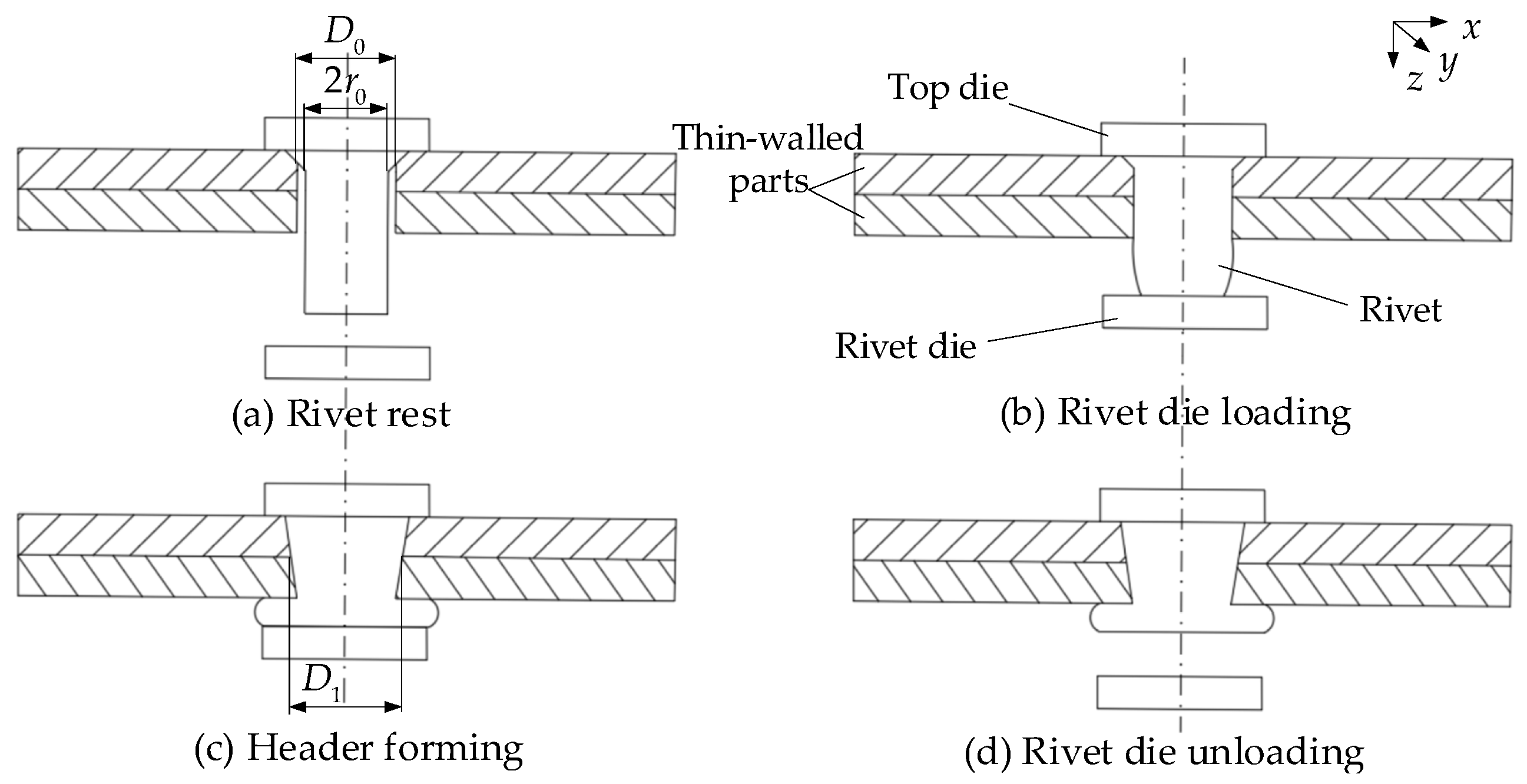
2. Non-Uniform Interference Amount in Single-Rivet Riveting

The riveting process of aircraft thin-walled components includes operation procedures such as positioning, clamping, making pilot holes, countersink, removing burrs, placing rivets, and riveting. This paper studies the deformation of thin-walled components caused by press riveting. The entire press-riveting process starts when the riveting die contacts the rivet, ends when the header is fully formed and the riveting die departs. As shown in Figure 1, this process can be described in four stages: (a) rivet rest, (b) rivet die loading, (c) header forming, and (d) rivet die unloading.
In the actual press riveting process, the rivet deforms under the action of press riveting force, causing the flow of rivet material, which subsequently contacts the pilot hole wall [15]. Due to the axial friction from the pilot hole wall acting on the rivet material and the presence of the top die. Therefore, when the contact area between the rivet material and the pilot hole is excessively large, the resistance encountered by the portion of the rivet material that has just entered the hole during its downward flow is extremely high. Further, according to the law of minimum resistance, when the axial flow of rivet material is hindered, its transverse flow becomes intense, and the rivet generates a transverse extrusion force. The extrusion force causes uneven distribution of riveting interference Δ z along the axial direction of the pilot hole. The riveting interference Δ z is half of the difference between the diameter of the deformed rivet shank D 1 and the initial pilot hole diameter D 0 ( Δ z = D 1 D 0 2 ).
As shown in Figure 2, a coordinate system is established for the single rivet joint structure after riveting. The non-uniform distribution of riveting interference along the axial direction is mainly affected by the friction of the pilot hole wall [16]; ignoring other influencing factors, a force analysis is conducted on the rivet. As shown in Figure 3a, the rivet shank is subjected to the press riveting force F z . Figure 3b shows the force acting on a micro-element of the rivet shank.
Axial Stress Equilibrium Equation of the Unit Element:
σ z = F z S σ z π r 2 θ 1 360 = σ z + d σ z π r 2 θ 1 360 + μ σ r 2 π r d z θ 1 360
In Equation (1), σ r is the radial stress of the shank; σ z is the axial stress of the rivet shank; μ is the friction coefficient of the contact surface between thin-walled parts and rivets; θ 1 is the angle of the micro-element; S is the cross sectional area of rivet shank; r is the radius from the axis.
Equation (1) is simplified to
d σ z R 0 + μ σ r d z = 0
In Equation (2), R 0 is the radius of initial pilot hole.
As the micro-element has a very small angle, it is considered to be in a plane stress state ( σ θ = 0 ). According to the Tresca yield criterion,
σ z σ r = σ s
In Equation (3), σ s is the yield stress of the rivet material.
By combining Equations (2) and (3), we obtain
d σ r + μ σ r R 0 d z = 0
The radial stress σ r is obtained from Equation (4):
σ r = C e μ z R 0
Before elastic springback, according to the equations from elastoplastic mechanics [17], the stress on the hole wall can be obtained:
p = σ s 3 ln 2 Δ z E 3 σ s + 1
Substitute Equation (6) into Equation (5) to obtain
σ r = p C e μ z R 0 = σ s 3 ln 2 Δ z E 3 σ s + 1
It is solved from Equation (7) that the distribution of the non-uniform interference amount is
Δ z = f z = 3 σ s 2 E e 3 σ s C e μ z R 0 1

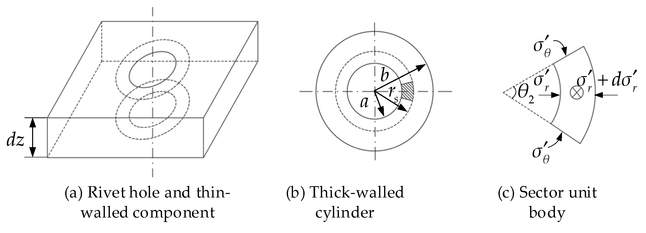
3. Non-Uniform Radial Stress in Single-Rivet Riveting

As illustrated in Figure 1d, with the removal of the riveting die, the press-riveting force decreases to zero, and a restricted springback occurs in both the rivet and the pilot hole [18]. Due to plastic deformation, the rivet, and control of the fixture, the pilot hole cannot be fully unloaded during the springback process. The springback amount is negligible, and the plastic deformation part remains.
The extrusion force acting on the pilot hole along the axial direction is uneven, resulting in non-uniform expansion of the pilot hole along the axial direction. A theoretical analysis is conducted on a thin-layer region with a thickness of d z , as shown in Figure 4a. In order to study the stress distribution law around the pilot hole, as shown in Figure 4b, the pilot hole and the thin-walled components are simplified as a thick-walled cylinder. As shown in Figure 4c, assume that the non-uniform radial stress formed by the rivet shank on the hole wall is p a . The radii of the inner and outer circles are a and, respectively. According to the elastoplastic theory, when a r r s , the inner part is the plastic deformation region; when r s r b , the outer part is the elastic deformation region, and r s is the radius of the boundary region between elastic and plastic deformation. Take a sector unit body with an angle of θ 2 .
Aircraft thin-walled components are predominantly fabricated from aluminum alloys, demonstrating strict adherence to Hooke’s law ( σ = E ε ) within the elastic regime and exhibiting isotropic behavior ( E x = E y = E z ). According to Lame’s Equation, the stress expression within the range of elastic deformation can be obtained:
σ r e = p a a 2 b 2 a 2 p a a 2 b 2 b 2 a 2 r 2 σ θ e = p a a 2 b 2 a 2 + p a a 2 b 2 b 2 a 2 r 2
In Equation (9), σ r e is the radial stress and σ θ e is the circumferential stress in the elastic zone.
According to the yield criterion,
σ θ σ r = σ s
In Equation (10), σ s is the yield stress of thin-walled components.
By combining Equations (9) and (10), the load p e at which the hole wall begins to yield at r = a is obtained as follows:
p e = b 2 a 2 2 b 2 σ s
As shown in Equation (11), at the elastic-plastic interface r = r s , the radial stress in the plastic zone is as follows:
p a s = b 2 r s 2 2 b 2 σ s
Chao and Kang [19,20] revealed that the influence of outer diameter b on riveting interference and stress becomes negligible when b approaches a critical threshold. Li [21] has shown that when the outer radius b of a compressed thick-walled cylinder is more than four times its inner radius a , the outer radius b has negligible effect on the Mises stress. Wu [22] conducted an elastoplastic analysis on the interference-fit pilot holes and found that when the outer radius b is more than three times the inner radius a , the effect of the outer radius b on the interference magnitude becomes negligible. The Aviation manufacturing engineering handbook [23] specifies that during riveting assembly, both hole-to-hole spacing and edge distance should exceed 10 R 0 . Thus, b approaches infinity large, and Equation (12) is simplified to
p a s = 1 2 σ s
As the riveting assembly process progresses, the thick-walled cylinder enters the plastic zone. In the plastic zone, the stress equilibrium equation is
d σ r p d r + σ r p σ θ p r = 0
In Equation (14), σ r p is the radial stress in the plastic zone, and σ θ p is the circumferential stress in the plastic zone.
By combining Equation (10) and Equation (14), we can obtain
d σ r p = σ s d r r
Integrating Equation (15), the radial stress distribution in the plastic zone can be obtained as
σ r p = σ s ln r + C 1
In Equation (15), C 1 is the integration constant.
Let the interference amount at the position with an axial distance of c from the coordinate system within the pilot hole be Δ c . According to the boundary condition that when r = a + Δ c , σ r p r = a + Δ c = p a c . By combining Equations (10) and (16), the stress distribution in the plastic zone at this position can be obtained as
σ r p = p a c + σ s ln r a + Δ c σ θ p = p a c + σ s ln 1 + r a + Δ c
When the radius of the plastic zone at this position is r = r s , the material is in the critical state of plastic yielding. Let σ r p r = r s = p a s , that is,
σ r p = p a c + σ s ln r a + Δ c = σ s 2
The radial stress at the position with an axial distance of c from the coordinate system can be obtained as
p a c = σ s ln r a + Δ c + σ s 2 = σ s ln r a + Δ c + 1 2
The distribution of the radial stress along the axis is
p a z = σ s ln r a + Δ z + σ s 2 = σ s ln r a + Δ z + 1 2

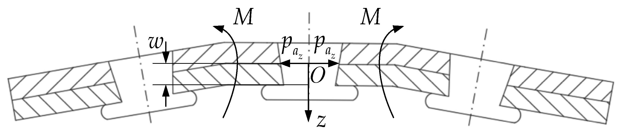
4. Riveting Deformation of Thin-Walled Components

After riveting assembly, the thin-walled component has shape accuracy requirements, such as surface smoothness, waviness, and edge profile values [23]. Moreover, after riveting assembly, the thin-walled component has negligible deformations in other directions [14]. Therefore, this paper analyzes the z-direction deformation of thin-walled components caused by riveting assembly.
After rivet assembly of thin-walled components, the uneven distribution of riveting interference along the thickness direction caused non-uniform radial stress distribution. When multiple rivets are riveted along the rivet seam, the non-uniform radial stress p a z creates a bending moment M , which results in plate bending deformation w . As shown in Figure 5, the plate may even exhibit a warped deformation distribution.
After riveting, the thin-walled component undergoes plastic deformation within an extremely small range near the hole edge, while the remaining parts are all in elastic deformation. Therefore, the riveting process will not cause the thin-walled component to be in a fully plastic state as a whole, but only generate local plastic deformation around the pilot hole. In the assembly of thin-walled components, the main focus of research is on the overall deformation rather than the local deformation. In order to analyze the deformation transfer law during the multi-rivet riveting process, the riveting deformation of the thin-walled component is approximated as elastic deformation under local plastic constraints, and the entire structure still remains within the range of elastic deformation [24].
The equivalent bending moment generated in the plate with a thickness of h by the non-uniform radial stress p a z is
M i = h 2 h 2 z p a z d z
Riveted components with identical parameters have the same stress states after riveting assembly [25]. According to the superposition principle in the mechanics of materials, on the premise that the deformation and internal stress do not exceed the proportional limit of the material, when multiple external loads act simultaneously, the rotation angle or the deflection of the part is equal to the linear superposition of those when each load acts alone, and the bending moments are continuously superimposed:
M x a l l = i = 1 n M x i M y a l l = i = 1 n M y i
For thin plates such as thin-walled components, which have a relatively small thickness, undergo small deformations, and are made of isotropic materials, the thin-plate theory can be adopted for analysis [26]. According to the definition of bending moment in Kirchhoff’s thin plate theory,
M x a l l = D 2 w x 2 + υ 2 w y 2 M y a l l = D 2 w y 2 + υ 2 w x 2
In Equation (23), x and y are the positions relative to the coordinate system, and D is the bending stiffness of the plate.
D = E h 3 12 1 υ 2
In Equation (24), E is the elastic modulus and υ is Poisson’s ratio of the material of the thin-walled component.
The deformation amount of the aircraft thin-walled component based on the non-uniform interference amount is therefore
w x , y = 1 2 M x υ M y D 1 υ 2 x 2 + M y υ M x D 1 υ 2 y 2

5. Experimental Verification

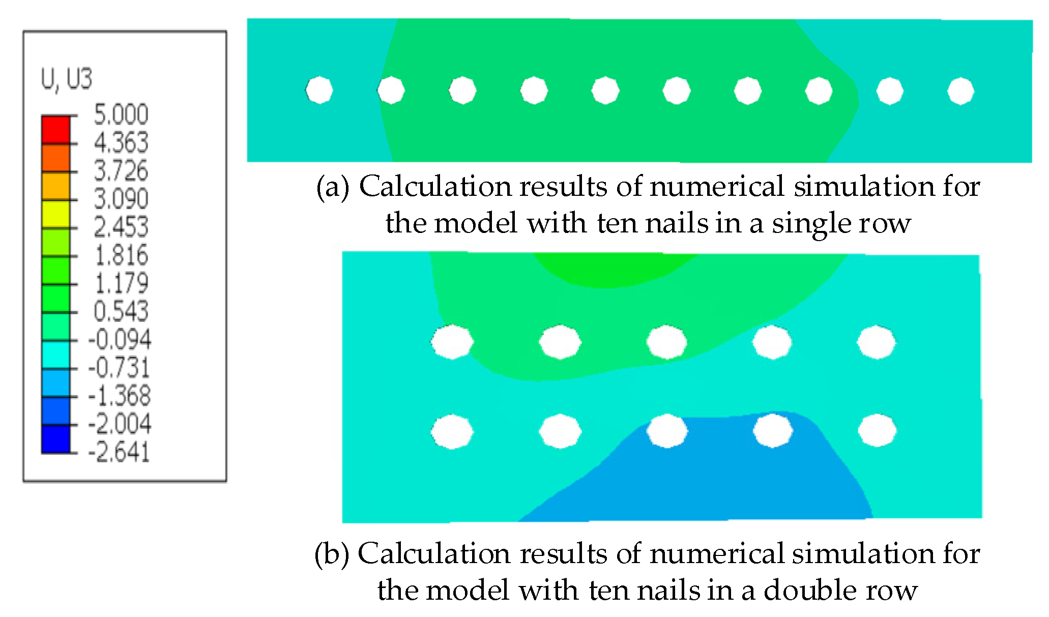
5.1. Numerical Simulation

The specifications of the thin-walled components are 275 mm × 50 mm × 2 mm and 150 mm × 75 mm × 2 mm, respectively. Countersunk head rivets complying with the industry standard HB6306 [23] are used. The rivets have a diameter of 3 mm and a length of 8 mm. According to the Aviation manufacturing engineering handbook [23], the pilot hole diameter is specified as 3.08 mm, both the hole-to-hole spacing and edge distance set to 25 mm, each exceeding 10 R 0 . The material of the thin-walled components used in the experiment is aluminum alloy LY12CZ, and the material of the rivets is aluminum alloy LY10. The material performance parameters are shown in Table 1 [27].
The riveting models of a single row with ten rivets and a double row with ten rivets are created using ABAQUS 2021, and the meshing is carried out as shown in Figure 6. The mesh element type selected is C3D8R, and all adopt hexahedral structural meshes. The total number of elements in the entire mesh model is 78,157, and the total number of nodes is 102,954. The contact relationships of each part in the model are set according to the master–slave relationship, and the friction coefficient between each part is 0.2 [28]. The riveting die and the backing bar are set as rigid bodies, and both the riveting die and the backing bar are fully constrained. The two ends of the thin-walled component are fixed and constrained. The riveting force is 9.5 KN as specified in the riveting standard in the Aviation Manufacturing Engineering Manual for the riveting force required for the upset head [23]. The riveting process of a single rivet is divided into three analysis steps: the loading step, the riveting die is used for riveting and forming; in the holding step, the riveting die remains stationary; in the unloading step, the riveting die retracts.

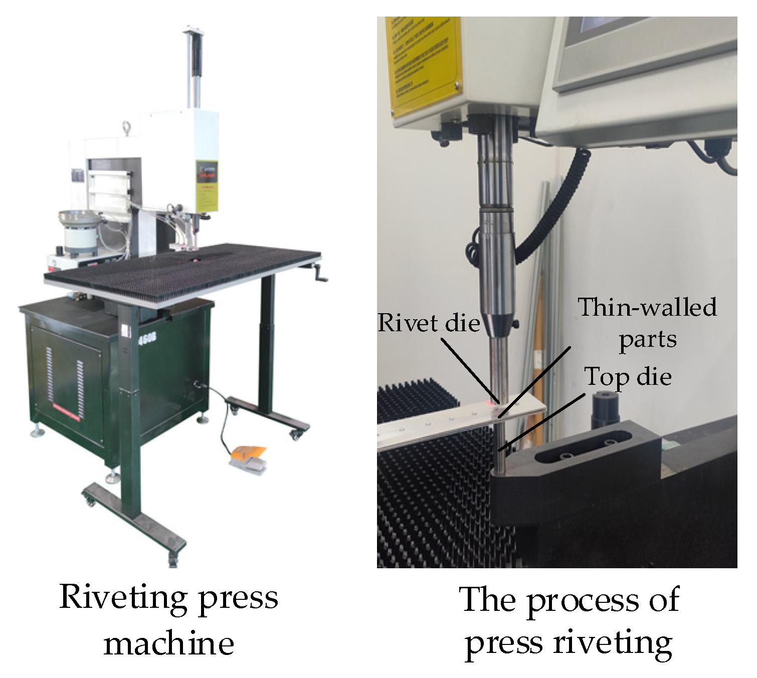
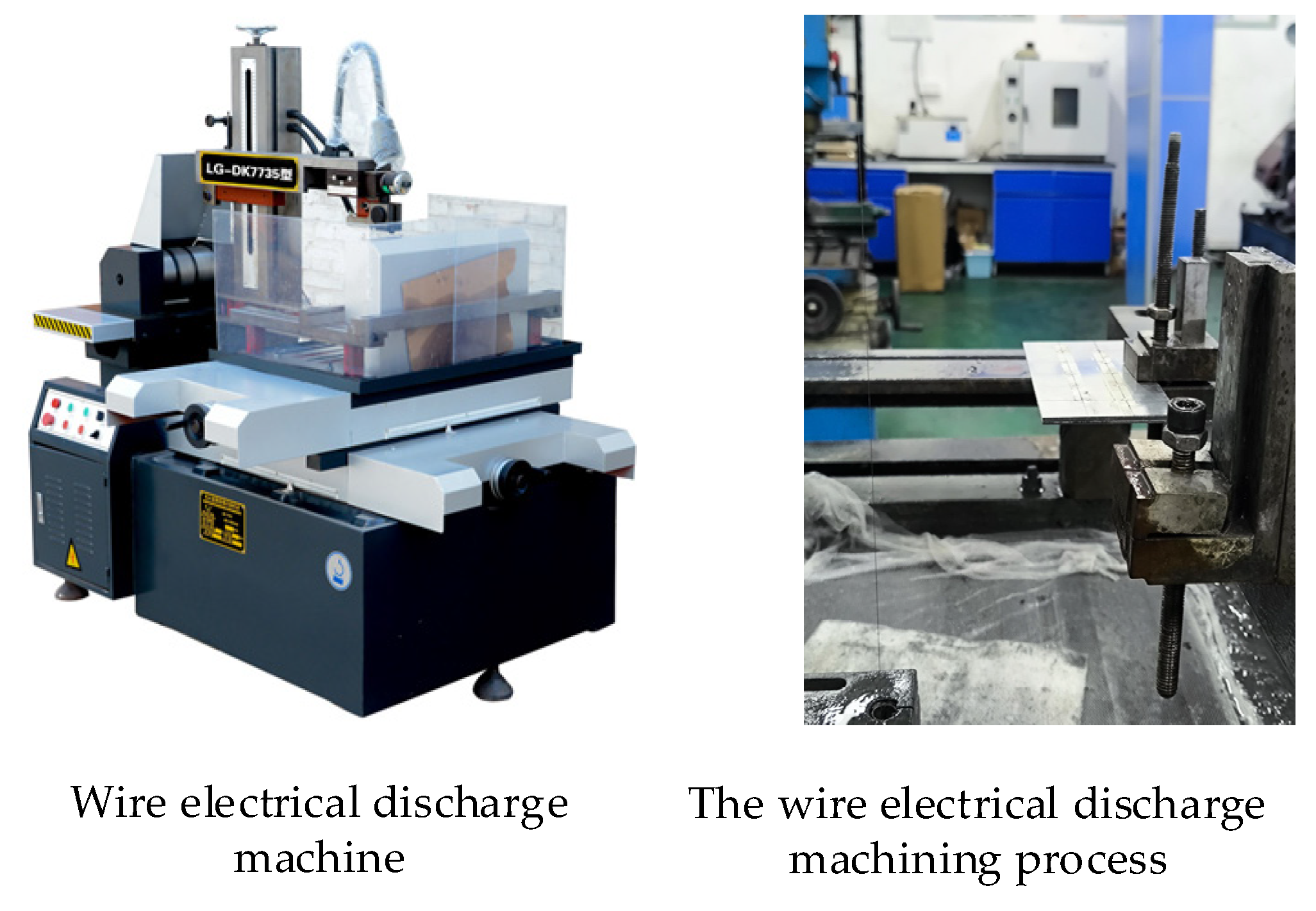
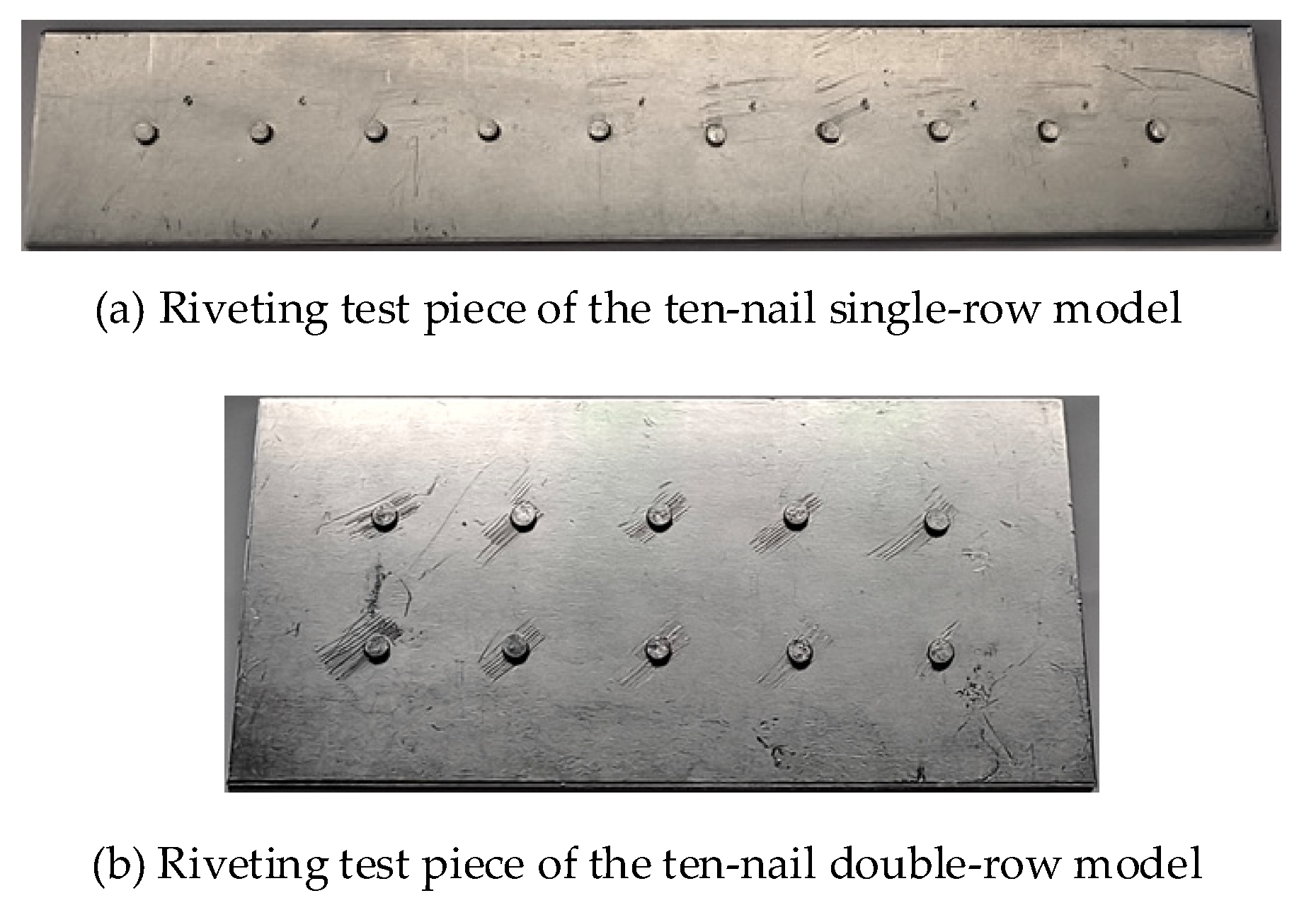
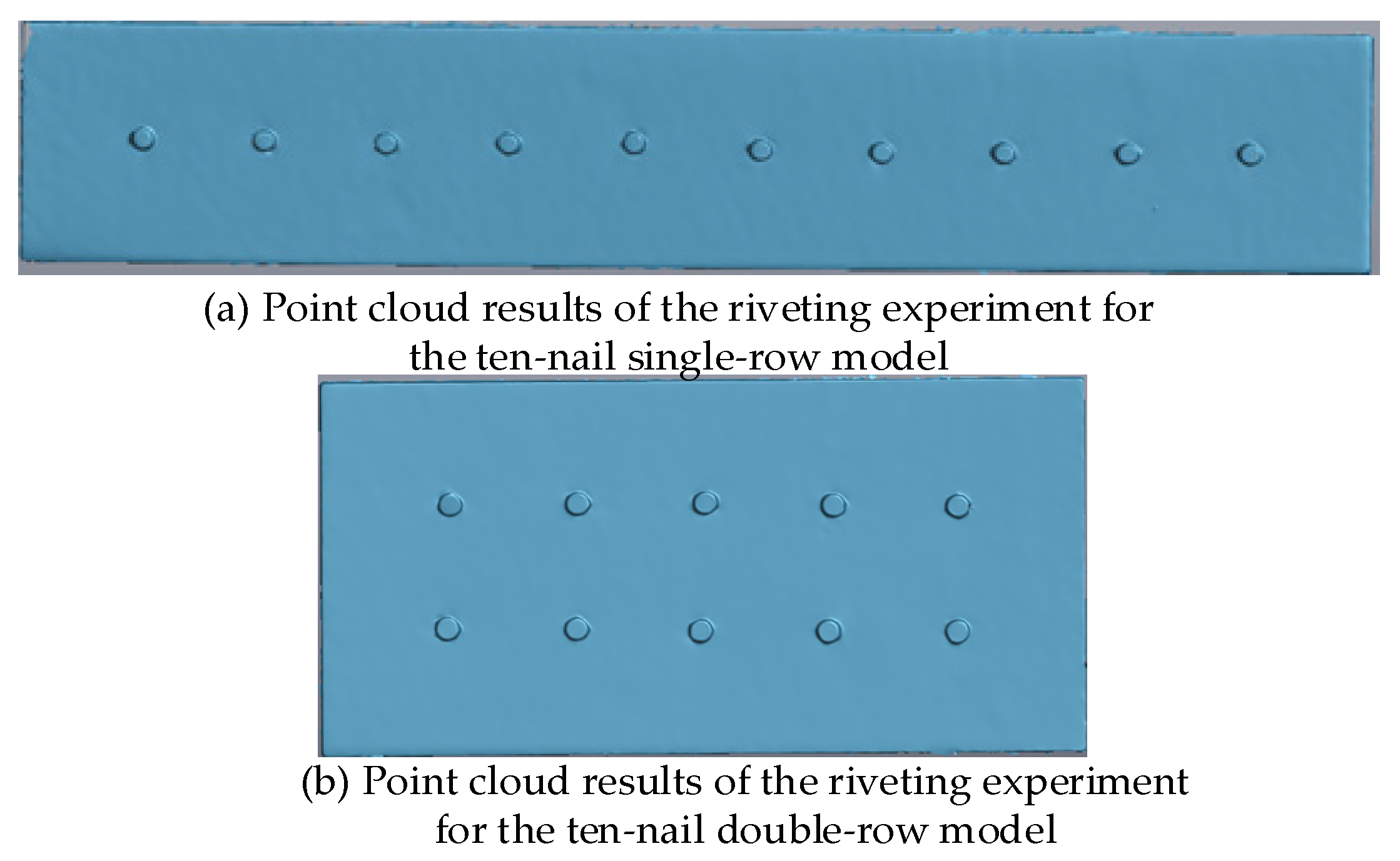
5.2. Riveting Experiment of Thin-Walled Components

As shown in Figure 7, experimental study on rivet assembly of thin-walled components was carried out on a riveting press machine (SP6-460B, Changzhou Senpai Intelligent Equipment Company Limited, Changzhou, China). To ensure the accuracy of the experiment, the materials and the structural dimensions of the riveting components used in the experiment were all the same as those in the finite element model. Also, the same riveting sequence was ensured, and the same riveting force as that in the numerical model was used. Use the riveting die to perform riveting on the riveted components. After the header is formed, unload the riveting die. As shown in Figure 8, a portable 3D laser scanner (M844-14-1C, Hexagon Metrology Technology Company Limited, Qingdao, China) was used to measure the deformation of the thin-walled components. Three-dimensional laser scanners leverage the laser ranging principle to rapidly reconstruct the 3D model and external shape data of thin-walled components. This is achieved by recording the 3D coordinates, reflectance, and texture information of numerous densely distributed points on the thin-walled component’s surface. As shown in Figure 9, for the rivet sectioning, a wire electrical discharge machine was used to cut the thin-walled components after riveting assembly.

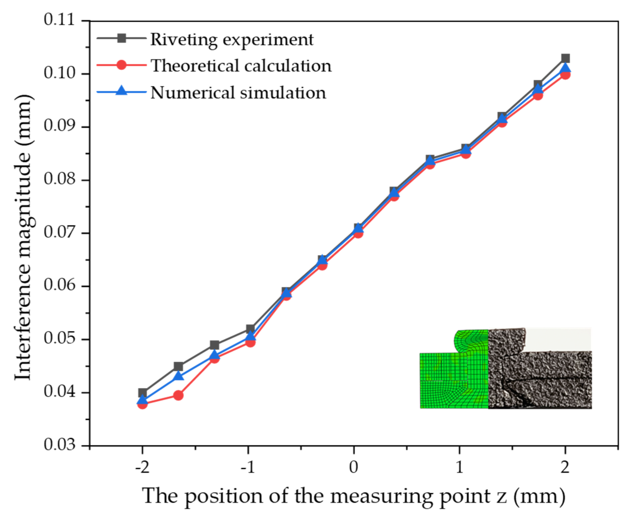
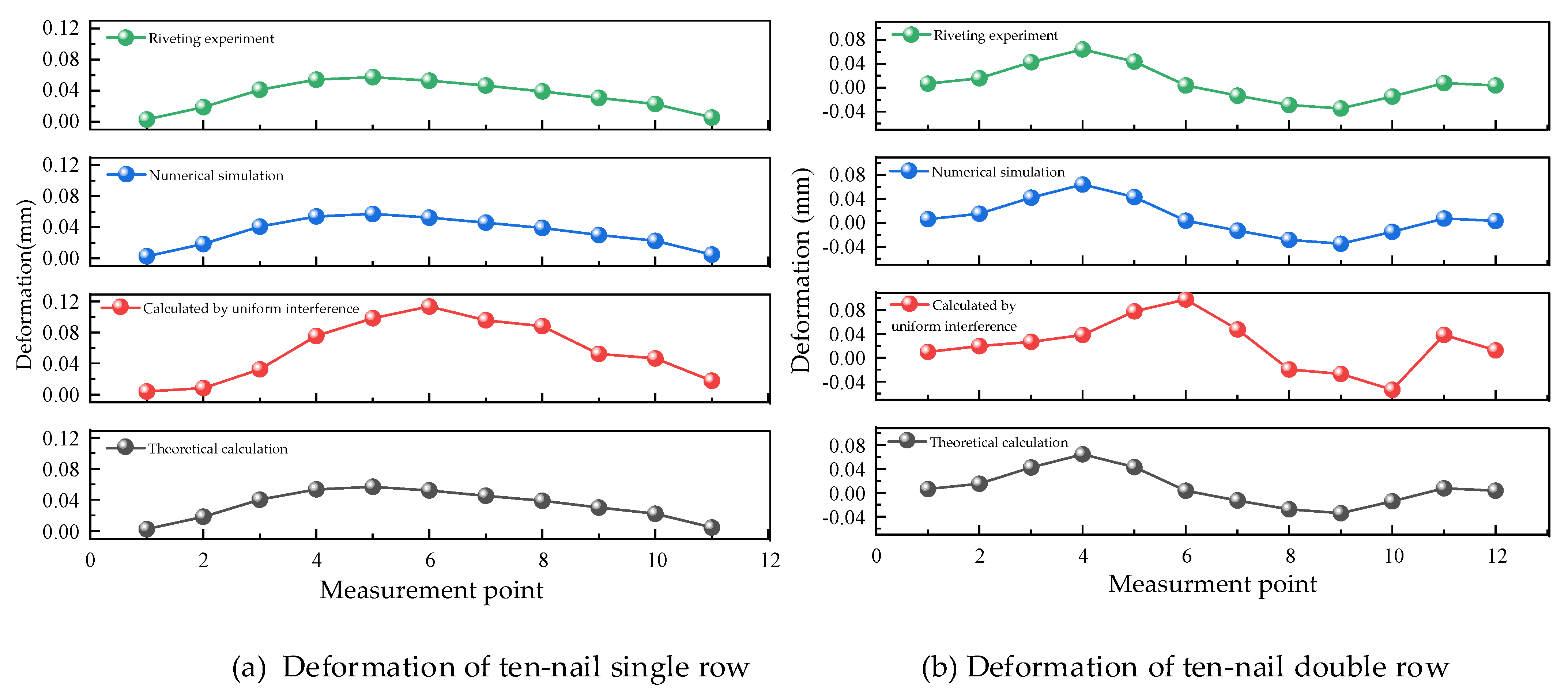
5.3. Calculation Results and Discussion

To verify the accuracy and effectiveness of the proposed method, the riveting interference amounts and the deformation amounts of thin-walled components in different tests will be studied and compared. In the assembly of thin-walled components, there are requirements for the contour accuracy. Therefore, the evaluation indexes of the deformation amount of thin-walled components include two aspects [25]: (1) the maximum deformation value v max of the measuring points; (2) the root mean square v r m s of the deformation of the measuring points. The maximum deformation value v max reflects the requirements for the outer contour values of the thin-walled components after riveting, and the root mean square v r m s represents the degree of dispersion of the deformation of the measuring points, which to a certain extent characterizes the smoothness of the outer contour of the thin-walled components. The calculation method of the root mean square of the deformation values of the measuring points is as follows:
v r m s = i = 1 n x i 2 / n
In Equation (26), n is the number of measuring points on the thin-walled components, and x i is the deformation value of the measuring point on the thin-walled components.
Figueira [6] calculates the overall deformation B z of the riveted parts based on the uniform interference amount:
B z = L + Y L 2 Y L 2 Y L 1 t t o t sin 2 Y L 2 Y L 1 t t o t
In Equation (27), L is the initial length of the riveted structural component, and Y L 1 and Y L 2 are the radial elongation amounts of the upper and lower plate components, respectively. Since this method is for predicting the deformation of riveted assembly based on the uniform interference amount, the interference amount of this method will not be compared.
In Figure 10, the distribution of the interference amount measuring points is shown, and Figure 11 shows the comparison of the interference amounts among the theoretical calculation, numerical simulation, and riveting experiment. It can be seen from the figures that the results of the numerical simulation and the experiment are in good agreement. Even in the detailed parts of the bonding surface, the sectional shapes are very close.
The distribution of the interference amount calculated by Equation (8) is basically consistent with the results of the numerical simulation and the real experiment. The error is relatively large near the upset head because of the influence of the friction at the upset head, which leads to a more serious expansion of the hole. However, the theoretical calculation ignores this process and only studies it as a thick-walled cylinder under internal force. The error at the nail head is also relatively large because the nail head comes into contact with the thin-walled components from the very beginning, resulting in less metal flow. The maximum error is 0.007 mm and the minimum is 0.001 mm. Similarly, these factors are not considered in the theoretical calculation. Therefore, there is a certain deviation between the above-mentioned regions and the theoretical calculation, but the range of these regions is relatively small.
As shown in Figure 12, in the models of ten nails in a single row and ten nails in a double row, 11 and 12 nodes, respectively, are taken at equal intervals on the midlines along the length direction as measuring points, the measurement point numbers are determined based on the numbers indicated in the figure. The calculation results at the measuring points in different experiments are compared, and the changes in the deformation values with the positions of the measuring points are also compared. The calculation results of the numerical simulation are shown in Figure 13, the test piece of the real experiment is shown in Figure 14, and the point cloud of the deformation measuring points of the real experiment is shown in Figure 15. The deformation amount of the thin-walled component during riveting is calculated by using MATLAB R2021b according to the theoretical equation, and the calculation results are shown in Figure 16.
The deformation results of thin-walled components in different experiments at each measuring point are shown in the Table 2 and Table 3.
As shown in Table 2 and Table 3, and Figure 17, the deformation variations in thin-walled components in theoretical calculations, numerical simulations, and real experiments are basically consistent, with highly consistent results. The experimental measurement results are greater than those of numerical simulations and theoretical calculations, which is due to the presence of positioning errors, part manufacturing errors, and human factors in the experiments.
The error C can be obtained by the following Equation:
C = A B B × 100 %
In Equation (28), A is the value of theoretical calculation or uniform interference calculation, and B is the value of numerical simulation or riveting experiment.
For the measurement points of the ten-nail single-row structure, the maximum errors of the theoretical calculations compared to the numerical simulations and real experiments are 0.5% and 0.3%, respectively, and the root mean square errors of the deformation values are 0.7% and 0.5%, respectively. The maximum errors of the calculations based on uniform interference compared to the numerical simulations and real experiments are 98.4% and 98.7%, respectively, and the root mean square errors of the deformation values are 79.5% and 80.0%, respectively.
For the measurement points of the ten-nail double-row structure, the maximum errors of the theoretical calculations compared to the numerical simulations and real experiments are 0.1% and 0.1%, respectively, and the root mean square errors of the deformation values are 27.7% and 30.3%, respectively. The maximum errors of the calculations based on uniform interference compared to the numerical simulations and real experiments are 52.0% and 52.0%, respectively, and the root mean square errors of the deformation values are 57.0% and 60.3%, respectively.
The traditional uniform interference calculation is based on the principle of linear superposition, which assumes that the overall deformation of thin-walled components after multi-rivet assembly can be characterized as the superposition of individual thin-walled component deformations induced by each single rivet. In practical riveting processes, non-uniform interference distribution induces non-uniform radial stresses. These stresses generate bending moments within individual riveted structures, which progressively accumulate through multi-rivet assemblies to form the total bending moment, ultimately leading to deformation in thin-walled components.
The prediction method based on non-uniform interference improves the prediction accuracy of all indicators by over 29% compared to the calculation method based on uniform interference, indicating that the theoretical calculation model has good prediction capabilities.

6. Conclusions

In order to improve the accuracy of the deformation prediction for riveted structures, a calculation model for predicting the riveting assembly deformation of aircraft thin-walled components based on the non-uniform interference amount was constructed. The effectiveness of the proposed model was verified by comparing theoretical calculations, numerical simulations, and real experiments. The following conclusions can be drawn from this study:
(1)
The non-uniform interference amount is an important factor causing the riveting deformation of thin-walled components. Through the stress analysis of the micro-element of the rivet shank, the axial distribution of the non-uniform interference amount was obtained. Based on the elastoplasticity theory, the riveting hole and the panel were simplified as a thick-walled cylinder. By combining with the axial distribution of the non-uniform interference amount, the distribution of the non-uniform radial stress was obtained. By projecting the single-rivet riveting onto the multi-rivet riveting, the total bending moment was obtained, and the deformation amount was calculated by using the thin plate theory.
(2)
Through numerical simulations and real experiments, it was verified that the interference amount is unevenly distributed. By comparing the interference amounts obtained from theoretical calculations, numerical simulations, and real experiments, the accuracy of the theoretical calculation of the uneven distribution of the interference amount was verified.
(3)
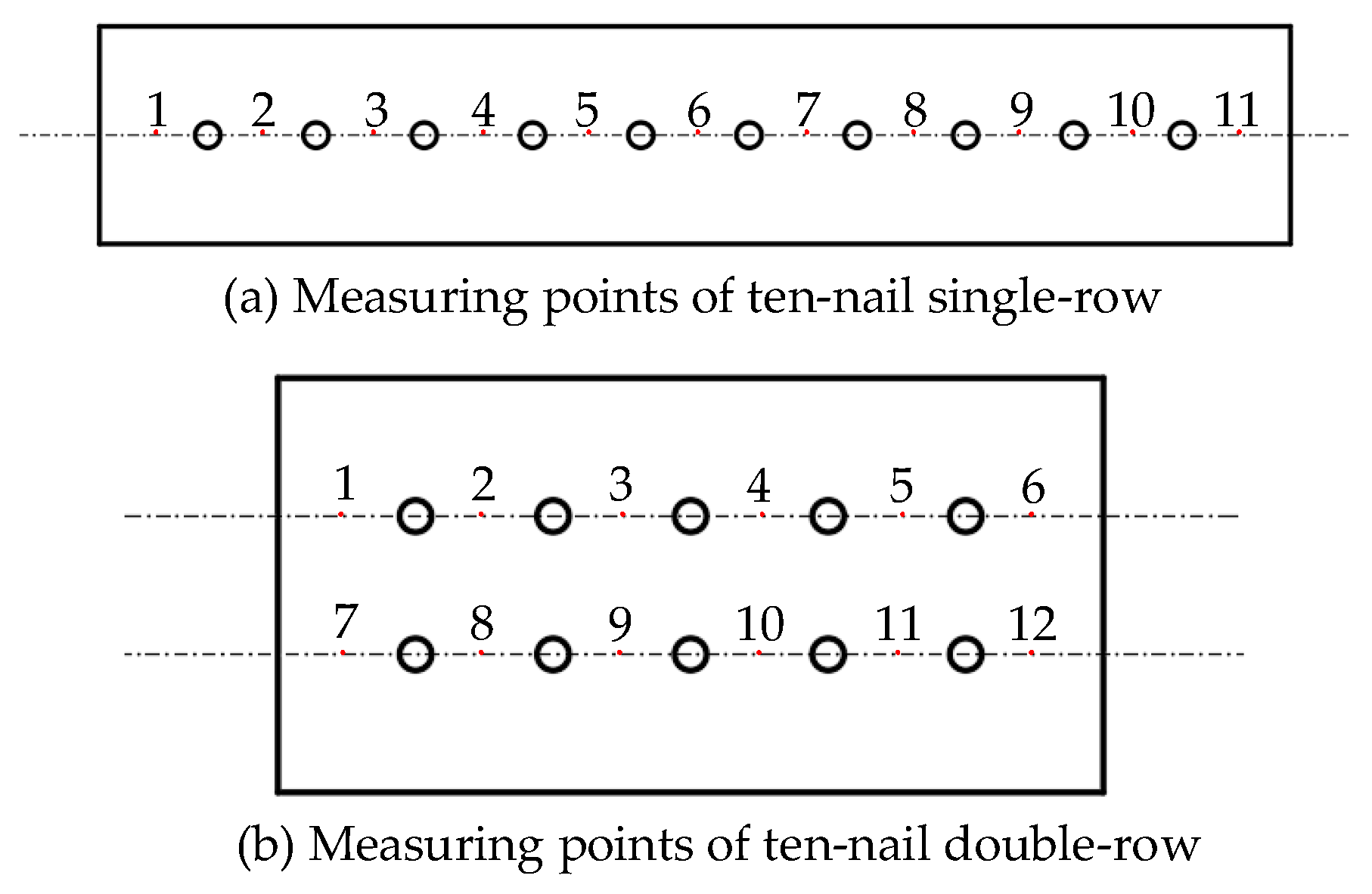
Through theoretical calculations, numerical simulations, and real experiments, it has been found that, among the measuring points of the single-row structure with ten rivets and the double-row structure with ten rivets, the deformation prediction model based on the non-uniform interference amount improves the prediction accuracy of various indicators by more than 29% compared with the calculation method of uniform interference. This further verifies the effectiveness and accuracy of the proposed prediction model. It provides a theoretical basis for the deviation transmission of aircraft digital assembly and process compensation, and enables more accurate control of aircraft assembly accuracy.

Author Contributions

Software, Y.H.; Formal analysis, Y.H.; Writing, Y.H.; Supervision, Y.Z.; Funding, Y.Z. All authors have read and agreed to the published version of the manuscript.

Funding

Please add: This research received the funding support to this research form The National Natural Science Foundation of China (Grant No. 52465060), the Aeronautical Science Foundation (Grant No. 2024M050056002), and the Key Research and Development Plan Project of Jiangxi Province (Grant No. 20243BBG71004).

Data Availability Statement

The original contributions presented in the study are included in the article, further inquiries can be directed to the corresponding author.

Conflicts of Interest

Author Yuanfan Hu is a postgraduate student at Nanchang Hangkong University. The remaining authors declare that the research was conducted in the absence of any commercial or financial relationships that could be construed as a potential conflict of interest.

References

  1. Wei, Y.; Su, M. Defect Detection Method for Aircraft Skin Riveting in Framework of YOLOv5. Mod. Aut. Technol. 2023, 7, 106–109. [Google Scholar]
  2. Kang, Y.; Li, G.; Song, S. Transfer and evolution of aircraft fuselage panel assembly deviation and optimization methods. Aerosp. Technol. 2024, 35, 40–51. [Google Scholar]
  3. Luo, Q.; Kang, Y.; Wang, T. Method of fast simulation, calculation and modeling of aircraft panel’s riveting deformation based on sub-structures. J. Mac. Des. 2024, 41, 1–8. [Google Scholar]
  4. Lv, G.; Li, C.; Zhao, C. Research on theoretical prediction method of rivet-forming quality considering different riveted structure parameters. Int. J. Adv. Manuf. Technol. 2024, 132, 2333–2345. [Google Scholar] [CrossRef]
  5. Jia, D.; Zhang, Q.; Xiong, L. A unified evaluation method for fatigue resistance of riveted joints based on structural stress approach. Int. J. Fatigue 2022, 160, 106871. [Google Scholar] [CrossRef]
  6. Figueira, J.A.N.; Trabasso, L.G. Riveting-Induced Deformations on Aircraft Structures. J. Aircr. 2015, 52, 2032–2050. [Google Scholar] [CrossRef]
  7. Liu, G.; Huan, H.; Ke, Y. Study on analysis and prediction of riveting assembly variation of aircraft fuselage panel. Int. J. Adv. Manuf. Technol. 2014, 75, 991–1003. [Google Scholar] [CrossRef]
  8. Kang, Y.; Song, S.; Wang, T. Analytical Modeling of Riveting Squeezing Force Considering Non-Uniform Deformation of Rivets in Aeronautical Structures. Materials 2024, 17, 2756. [Google Scholar] [CrossRef]
  9. Liang, Q.; Zhang, T.; Zhu, C. Effect of riveting angle and direction on fatigue performance of riveted lap joints. Coatings 2021, 11, 236. [Google Scholar] [CrossRef]
  10. Nejad, R.M.; Berto, F.; Tohidi, M. Fatigue performance prediction of Al-alloy 2024 plates in riveted joint structure. Eng. Fail. Anal. 2021, 126, 105439. [Google Scholar] [CrossRef]
  11. Kondo, A.; Kasahara, T.; Kanda, A. A simplified finite element model of riveted joints for structural analyses with consideration of nonlinear load-transfer characteristics. Aerospace 2021, 8, 196. [Google Scholar] [CrossRef]
  12. Kang, Y.; Song, S.; Wang, T. Study on the Mechanism of Cumulative Deformation and Method for Suppression in Aircraft Panel Riveting. Aerospace 2024, 11, 678. [Google Scholar] [CrossRef]
  13. Ni, J.; Tang, W.; Xing, Y. A local-to-global dimensional error calculation framework for the riveted assembly using finite-element analysis. J. Manuf. Sci. Eng. 2016, 138, 031004. [Google Scholar] [CrossRef]
  14. Yang, D.; Qu, W.; Ke, Y. Local-global method to predict distortion of aircraft panel caused in automated riveting process. Assem. Autom. 2019, 39, 973–985. [Google Scholar] [CrossRef]
  15. Silvayeh, Z.; Brillinger, M.; Domitner, J. Deformation behavior of aluminum alloy rivets for aerospace applications. J. Mater. Res. Technol. 2024, 33, 3482–3491. [Google Scholar] [CrossRef]
  16. Zanatta, C.V.; Villani, E.; Mello, J.M.G. Riveting process simulation to predict induced deformations in aeronautical structures. Int. J. Adv. Manuf. Technol. 2022, 120, 7673–7687. [Google Scholar] [CrossRef]
  17. Li, Y. Principles of Plastic Forming of Metals; China Machine Press: Beijing, China, 2013. [Google Scholar]
  18. Zheng, B.; Yu, H.; Lai, X. Assembly deformation prediction of riveted panels by using equivalent mechanical model of riveting process. Int. J. Adv. Manuf. Technol. 2017, 92, 1955–1966. [Google Scholar] [CrossRef]
  19. Chao, Z.; Wei, T.; Xiang, Y. Experimental and numerical studies of stress/strain characteristics in riveted aircraft lap joints. J. Mech. Sci. Technol. 2019, 33, 3245–3255. [Google Scholar]
  20. Kang, Y.; Huan, X.; Zi, W. Three-Dimensional Characterization of Residual Stress in Aircraft Riveted Panel Structures. Aerospace 2024, 11, 552. [Google Scholar] [CrossRef]
  21. Li, Y. An Analysis of Riveting Process by Theoretical Nonlinear Finite Element and EXPERIMENTAL methods. Doctor Thesis, Wichita State University, Wichita, Kansas, 1998. [Google Scholar]
  22. Wu, S. Elastic-plastic analyses of fastener holes of interference-fit rivets and its application in fatigue life estimation. Aerosp. Technol. 1989, 12, 662–665. [Google Scholar]
  23. Aviation Manufacturing Engineering Handbook Editorial Board. Aviation Manufacturing Engineering Handbook (Aircraft Assembly); Aviation Industry Press: Beijing, China, 2010. [Google Scholar]
  24. Chang, Z.; Wang, Z.; Jiang, B. Modeling and predicting of aeronautical thin-walled sheet metal parts riveting deformation. Assem. Autom. 2016, 36, 295–307. [Google Scholar] [CrossRef]
  25. Chang, Z.; Wang, Z.; Xie, L. Prediction of riveting deformation for thin-walled structures using local-global finite element approach. Int. J. Adv. Manuf. Technol. 2018, 97, 2529–2544. [Google Scholar] [CrossRef]
  26. Xu, Z. The Theory of Elasticity (I, II); Higher Education Press: Beijing, China, 2016. [Google Scholar]
  27. China Aeronautical Materials Handbook Editorial Committee. China Aeronautical Materials Handbook; Standards Press of China: Beijing, China, 2001. [Google Scholar]
  28. Baha, S., II; Hesebeck, O. Simulation of the solid rivet installation process. SAE Int. J. Aerosp. 2010, 3, 187–197. [Google Scholar] [CrossRef]
Figure 1. Press riveting process.
Aerospace 12 00526 g001
Figure 2. Coordinate system of the riveting structure.
Aerospace 12 00526 g002
Figure 3. Stress distribution of rivet shank and micro-element.
Aerospace 12 00526 g003
Figure 4. Stress analysis of pilot hole.
Aerospace 12 00526 g004
Figure 5. Riveting deformation of thin-walled parts.
Aerospace 12 00526 g005
Figure 6. Mesh generation.
Aerospace 12 00526 g006
Figure 7. The riveting machine and the riveting process.
Aerospace 12 00526 g007
Figure 8. The scanner and the scanning process of thin-walled components.
Aerospace 12 00526 g008
Figure 9. Wire cutting machine and wire cutting process of thin-walled components.
Aerospace 12 00526 g009
Figure 10. Distribution of measuring points for interference amount.
Aerospace 12 00526 g010
Figure 11. Comparison of interference amounts.
Aerospace 12 00526 g011
Figure 12. Distribution of measuring points.
Aerospace 12 00526 g012
Figure 13. Results of numerical simulation calculation.
Aerospace 12 00526 g013
Figure 14. Specimens for riveting experiments.
Aerospace 12 00526 g014
Figure 15. Scanned point cloud of riveting experiments.
Aerospace 12 00526 g015
Figure 16. Deformation results of theoretical calculation.
Aerospace 12 00526 g016
Figure 17. Comparison of deformation amounts at measuring points of thin-walled components.
Aerospace 12 00526 g017
Table 1. Material performance parameters [27].
MaterialElastic Modulus (GPa)Poisson’s RatioYield Stress (MPa)
LY12CZ72.40.33350
LY1071.00.33247
Table 2. Results of deformation amounts for a single row of ten rivets (mm).
MethodMeasurement PointIndex
1234567891011 v m a x v r m s
Theoretical calculation0.00230.01810.04020.05360.05680.05210.04530.03860.03010.02220.00450.05680.0378
Calculated by uniform interference0.00410.00850.03240.07560.09820.11330.09570.08810.05230.04650.01790.11330.0684
Numerical simulation0.00270.01860.04090.05390.05710.05250.04590.03890.03020.02260.00490.05710.0381
Riveting experiment0.0030.0180.0410.0540.0570.0520.0460.0390.0300.0220.0050.0570.038
Table 3. Results of deformation amounts for two rows of ten rivets (mm).
MethodMeasurement PointIndex
123456789101112 v m a x v r m s
Theoretical calculation0.00610.01510.04230.06390.04260.0034−0.0128−0.0276−0.0343−0.01420.00730.00320.06390.0378
Calculated by uniform interference0.00960.01940.02650.03810.07750.09730.0475−0.0196−0.0268−0.05330.03790.01270.09730.0465
Numerical simulation0.00630.01550.04250.06400.04310.0036−0.0131−0.0283−0.0346−0.01460.00750.00340.06400.0296
Riveting experiment0.0060.0150.0420.0640.0430.003−0.013−0.028−0.034−0.0140.0070.0030.0640.029
Disclaimer/Publisher’s Note: The statements, opinions and data contained in all publications are solely those of the individual author(s) and contributor(s) and not of MDPI and/or the editor(s). MDPI and/or the editor(s) disclaim responsibility for any injury to people or property resulting from any ideas, methods, instructions or products referred to in the content.

