Abstract
This study investigates the basic characteristics of force transmissibility for a passive launch and on-orbit vibration isolation system (PLOVIS-II), which was developed to examine the microvibration attenuation of a spaceborne cryogenic cooler. The design, based on a coil spring-type passive vibration isolation system without an additional launch-lock device, demonstrated an effective vibration attenuation performance in both launch and on-orbit vibration isolation. In this study, a test setup and method were developed to measure the force transmissibility of an isolator along each axis using a voice-coil-type non-contact vibration excitation instrument. In addition, the test results included the position sensitivity of PLOVIS-II, considering the worst misalignment of the isolation system, and its performance was compared with that of PLOVIS-I proposed in a previous study.
1. Introduction
To acquire high-quality images from high-resolution observation satellites with sub-meter accuracy, it is essential to isolate microvibrations generated by disturbance sources, including on-board payloads of satellites featuring mechanical moving parts [1]. Cryogenic coolers of the pulse-tube type have been extensively employed in space applications to cool the focal planes of infrared imaging sensors, offering benefits such as simplicity, cost-efficiency, enhanced reliability, and reduced mechanical vibrations compared to traditional Stirling-type coolers [2,3,4]. However, this cooler also generates undesirable microvibrations during on-orbit operation, which can significantly impact the performance of microvibration-sensitive payloads on observation satellites. Future space missions, such as high-precision terrestrial and celestial observation satellites, demand stricter microvibration requirements, and effective microvibration isolation has become essential for such cooler systems. To prevent image quality degradation, one effective approach is to incorporate a vibration isolator to attenuate microvibrations transmitted to microvibration-sensitive on-board payloads.
The microvibration of the cooler can be effectively mitigated by separating its operating frequency from the natural frequency of the cooler assembly using a vibration isolator. Passive vibration isolation systems represent an effective strategy for vibration mitigation, distinguished by their robustness, simplicity, and reliability [5,6,7,8,9,10,11,12,13,14]. Several types of passive vibration isolation systems have been proposed in previous studies. Ellis et al. [5] proposed a vibration isolator using a commercial wire rope that supports a cryocooler system on a cube satellite. A wire rope isolator can be readily integrated with minimal modifications to the cryocooler, effectively attenuating the microvibrations generated by the cryocooler. Richard et al. [6] introduced a hexagonal vibration isolator featuring low stiffness intended to support spaceborne coolers. Microvibration measurement tests were conducted to validate the system design. The test results demonstrated that the vibration isolator achieved a 20 dB attenuation of harmonic disturbances generated by the cooler. Riabzev et al. [7] designed a passive multidimensional vibration isolator that incorporates a coil spring with low lateral stiffness, utilizing a three-stage spring-mass system affixed to the cold tip of a cryogenic cooler. The effectiveness of the isolation system was assessed experimentally in conjunction with analytical models. To support micro-vibration isolation of cryogenic coolers, Kamesh et al. [8] proposed a variety of flexible passive vibration isolators, including struts with different thicknesses and bending properties, adopting a frequency decoupling approach between the operational frequency of the cooler and the natural frequency of the isolation system. Takei et al. [9] proposed a passive two-stage type vibration isolator intended for the cryogenic cooler of the ASTRO-H satellite. The system includes a launch vibration isolator with a cast viscoelastic bumper and an on-orbit isolator characterized by metal bending properties. It offers broadband jitter isolation during on-orbit operations and reduces vibration loads in the launch environment. The effectiveness of this design was confirmed using both numerical analyses and experimental methods. Takuma et al. [10] proposed a flux-pinned passive microvibration isolator for applications in cryogenic cooling. This mechanism leverages flux pinning to passively sustain the relative distance and position between a permanent magnet and a cooled type-II superconductor, facilitated by the flux pinning force. The isolator’s characteristics, including spring and damping coefficients, were analyzed using a numerical model. Yang et al. [11] proposed a passive vibration isolator comprising a double-deck leaf spring filled with silicone rubber, specifically designed for space optical payloads. This design minimizes stress on the leaf-type springs while enhancing the damping coefficient, thereby improving its effectiveness in attenuating vibrations within the optical payload. The effectiveness of the vibration isolator was validated through dynamic modeling, finite element analysis (FEA), and experimental testing, with results confirming the validity of the analytical approach and demonstrating efficient attenuation of spaceborne disturbances. Robinson et al. [12] developed a soft mount featuring a low-stiffness passive vibration isolation system, which employs metallic flexures and viscoelastic damping materials for a Thermal Infrared Sensor (TIRS) cryogenic cooler. The stiffness of the metallic flexures was calibrated to ensure that the rigid-body mode of the TIRS cooler mounted on the flexures fell within the range of 9 to 30 Hz, leading to a tenfold improvement in vibration isolation performance. Kwon et al. [13] introduced a superelastic shape memory alloy (SMA) blade-type vibration isolator that effectively provided the desired jitter isolation performance under both 0 g and 1 g conditions. This isolator ensures the structural integrity of the cooler assembly without necessitating an additional launch locking system, even under severe launch vibration conditions, and effectively isolates microvibrations of the cooler in the orbital environment. The results of position sensitivity tests indicated that the isolator could maintain stable jitter isolation performance, even under the influence of 1 g. Kwon et al. [14] introduced a multilayered blade-type isolator utilizing double-sided adhesive tape to mitigate microjitter generated by cryogenic coolers in space applications. The isolator’s insensitivity to positional variations enables consistent jitter reduction performance. Furthermore, the efficacy of this design, which does not require additional launch locks, was validated through qualification-level launch vibration tests. The experimental results demonstrated that the system achieved an isolation performance of 20 dB against harmonic disturbances produced by the cooler.
In passive isolators, the use of low-stiffness components facilitates the decoupling of the cooler’s primary operating frequency from the natural frequency of the supported cooler assembly, thereby effectively reducing microvibrations. However, the structural integrity of coolers utilizing low-stiffness isolators may be insufficient to withstand the harsh conditions of the launch environment. This challenge could be addressed by integrating a hold-and-release mechanism for the cooler assembly during launch. However, this solution adds complexity to the system and increases overall mass. If the hold-and-release mechanism fails to disengage the mechanical constraints of the isolation system in orbit, the isolator may not ensure adequate performance, potentially leading to degradation of the optical system’s functionality.
To address these challenges, Oh et al. [15] developed a passive launch and on-orbit vibration isolation system (PLOVIS-I) with space heritage as part of the KOMPSAT-3A program [16]. PLOVIS-I effectively mitigates microvibrations from a cryogenic cooler in both launch and orbital environments, removing the necessity for an additional hold-and-release mechanism. The system achieves effective microvibration isolation through the use of three coil springs characterized by comparatively low lateral stiffness. However, position sensitivity tests indicated a normalized transmitted force ratio of 4.52 between 0 g and 1 g, suggesting that the isolation performance is significantly influenced by the precise alignment of the isolator, which is critical for optimal functioning. It is noteworthy that Oh et al. [15] did not assess the position sensitivity of the conventional PLOVIS-I. Additionally, vibration tests conducted to evaluate the design’s effectiveness at the qualification level for launch conditions demonstrated that PLOVIS-I was insufficient for attenuating sine vibration loads due to the inadequate damping properties of the coil springs, even though the maximum acceleration experienced by the cooler remained within its design limit load.
In view of the position sensitivity of the conventional PLOVIS-I, Park et al. [17] proposed a dual coil-spring-type passive vibration isolation system (PLOVIS-II) that exhibited improved performance in isolating micro-vibrations and the attenuation of launch vibration loads. PLOVIS-II uses coil springs with low stiffness to isolate the microjitter during on-orbit operation and coil springs with relatively higher stiffness to attenuate the launch vibration loads. The key features of PLOVIS-II are its low sensitivity to the alignment position of the isolator and reduced launch vibrations compared to the conventional PLOVIS-I. The effectiveness of the design was validated through microvibration isolation and launch environment vibration tests. Although position sensitivity was measured with respect to the aligned position of the isolator, the sensitivity was only investigated for the main excitation frequency of the cooler in a previous study [17]. Coolers generally generate harmonic vibrations that are coupled with their main driving frequency. Therefore, for the thermal control of the cooler, it is essential to analyze the effects of dynamic coupling with the elastic vibration modes of the structure that supports the cooler, including the heat pipes. This implies that the dynamic characteristics of vibration isolators are required to be in a much wider frequency range.
In this study, to measure the force transmissibility characteristics of PLOVIS-II under 0 g simulation conditions over the frequency range from 50 Hz to 250 Hz, a test method using a non-contact-type vibration exciter consisting of a voice coil and permanent magnet was proposed and investigated. The position sensitivities of PLOVIS-II and PLOVIS-I were compared. According to the test results obtained, the dual-coil spring-type isolator of PLOVIS-II showed lower sensitivity to the aligned position of the isolation system than that shown by PLOVIS-I with a single-coil spring.
The organization of the remaining sections of this paper is as follows: Section 2 provides an overview of previous studies on PLOVIS-II, including the results of the design and validation tests. Section 3 and Section 4 present the design of the force transmissibility tests and the results of the on-ground force transmissibility testing, including position sensitivity tests.
2. Summary of PLOVIS-II
2.1. Design Description of PLOVIS-II [17]
Figure 1 shows the configuration of the cooler assembly using PLOVIS-II. The cooler assembly consists of a cooler, transfer line, and vibration isolator (PLOVIS-II). A transfer line is connected to the cold finger of the IR sensor to cool its focal plane. The thermal interface for integrating the heat pipe is located at the top of the cooler, although this is not shown in the figure. The microvibration of the cooler is attenuated by the PLOVIS-II assembly, which is integrated into the center of the cooler’s gravity plane to minimize the moment of the cooler assembly in the launch vibration environment.
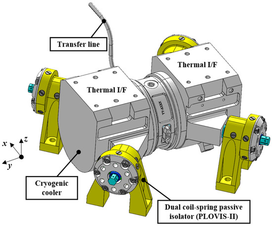
Figure 1.
Configuration of the cooler assembly using PLOVIS-II.
Figure 2a and Figure 2b, respectively, show an exploded view and integrated configuration of PLOVIS-II [17]. PLOVIS-II comprises high- and low-stiffness coil springs, moving plates, displacement limiters, a mechanical shaft cover, and a support structure. Low-stiffness coil springs connect the support structure and mechanical shaft cover. The movement of the shaft cover, which is supported by a low-stiffness coil spring, is limited to ±1.2 mm for all axes by the moving plate, which is supported by a high-stiffness coil spring. Therefore, the main factor that guarantees the microvibration isolation performance is the nominal position of PLOVIS-II during the on-orbit operation of the cooler, as shown in Figure 2b. This position, which is recovered by the resilience of the low-stiffness coil springs contracted or extended in the launch 1 g environment, ensures a relatively low-stiffness isolation system along the longitudinal direction of the cooler, corresponding to the excitation axis of the cooler. This enables the separation of the main excitation frequency of the cooler from the eigenfrequency of the PLOVIS-II system. In contrast, a high-stiffness coil spring connects the moving plate and the support bracket. The movement of the moving plate, which is supported by high-stiffness coil springs in a launch environment, is limited by the displacement limiter to ±0.8 mm along the in-plane direction. A coil spring with a high axial stiffness value (9.8 N/mm) was chosen to support the cooler in the direction of gravity under the 1 g condition. Therefore, mechanical contact occurs exclusively between the moving plate and the shaft cover, while no contact occurs between the shaft cover and the displacement limiter. This design attenuates the transmitted microvibration level during cooler operation. This is unlike the design in PLOVIS-I, where the shaft cover comes in direct contact with the displacement limiter when unexpected misalignments and thermal distortion of the heat pipes are additionally integrated in the cooler for heat transportation from the cooler. This implies that PLOVIS-II, with a dual-coil spring design, is less sensitive than PLOVIS-I to the alignment position of the vibration isolator. Figure 3a–c show the position of the moving plate supported by the high-stiffness coil spring as a function of the number of coil springs applied to simulate the spring-fracture conditions. These figures show that the moving plate was in contact with the support structure, even after the three coil springs had failed. However, the shaft cover is supported by low-stiffness springs even when it is not in contact with the moving plate. This means that the microvibration attenuation performance of PLOVIS-II will not be affected even if the high-stiffness coil spring is fractured, such as in a severe launch vibration environment.
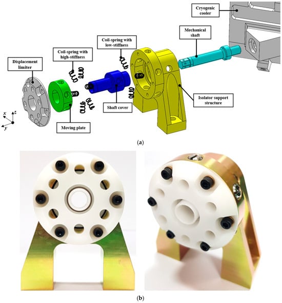
Figure 2.
Configuration of PLOVIS-II ((a) exploded view and (b) front and isometric views).
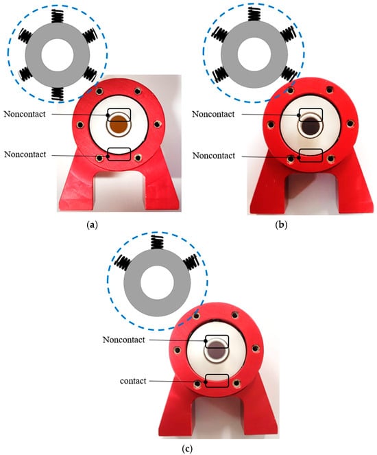
Figure 3.
Position of the moving plate as a function of the number of coil springs applied to simulate the spring fracture condition ((a) normal condition, (b) condition of one spring fracture simulation, and (c) condition of three spring fracture simulations).
Prediction of on-orbit micro-vibration isolation performance based on a passive system is achievable using the one-degree-of-freedom (1-DOF) mathematical model. In this model, only the excitation along the longitudinal axis of the cooler, which serves as the primary excitation direction during cooler operation, is considered. The cooler mass m is supported by a series of elastic elements, including the heat pipe (khp = 1.05 N/mm), transfer line (ktl = 0.57 N/mm), and the PLOVIS-II isolator, which comprises low-stiffness coil springs (ksp) and a damping element with coefficient csp. The disturbance force generated during cooler operation is modeled as a harmonic excitation:
where ω is the driving frequency of the cooler, and f0 is the force amplitude. The on-orbit micro-vibration isolation strategy aims to decouple the excitation frequency ω from the natural frequency of the supporting structure, given by
where the equivalent stiffness is defined as
To prevent resonance coupling between the excitation and the structural modes of vibration-sensitive optical payloads, should be minimized. This reduction shifts ωn away from ω, thereby improving micro-vibration isolation performance. The transmissibility (TR) of the disturbance force transmitted to the base is expressed as a function of damping ratio of the PLOVIS-II (ζ) and frequency ratio γ = ω/ωn:
The predicted micro-vibration isolation performance of the proposed PLOVIS-II system is approximately 32 times lower than that of the rigid condition without an isolator when the driving frequency ω is set to 50 Hz, based on the mathematical model. The system parameters used in this estimation, including ksp and ζ, were derived from a free-vibration test of a dummy cooler assembly under an on-orbit 0 g simulation condition using the same test configuration described in [15]. These parameters are summarized in Table 1.

Table 1.
Basic characteristic value for PLOVIS-II.
To reduce launch vibrations, the moving plates, displacement limiters, and shaft covers were made of Delrin [18], a high-damping plastic material with space heritage. The design was aimed at dissipating and mitigating the launch vibration loads transmitted to the cooler during the contact and slip between the plastic materials and those with high damping characteristics. Moreover, the moving plates supported by high-stiffness coil springs influence the attenuation of launch vibration loads when the shaft cover bumps against the moving plates. This may be more effective than the conventional PLOVIS-I in reducing the launch vibration loads transmitted to the cooler.
2.2. Design Validation of PLOVIS-II [17]
Design validation of PLOVIS-II was performed through launch vibration environment tests and microvibration measurement tests. PLOVIS-I was also tested to confirm the performance improvement achieved by PLOVIS-II, although the results are not shown here. Details of the test setup and specifications for each test of PLOVIS-I and PLOVIS-II were presented in a previous study [17].
2.2.1. Launch Vibration Environment Test
Qualification-level sine and random vibration tests were conducted to validate the design of PLOVIS-II in a launch environment. These tests focused on the technical aspects of whether PLOVIS-II achieved attenuation of the launch vibration loads on the cooler more effectively compared with PLOVIS-I.
Figure 4 shows the representative sine vibration test results of PLOVIS-II during z-axis excitation. The highest acceleration response level of the dummy cooler with PLOVIS-II was measured to be 20.9 g, which is 45% lower than the 46.2 g design load of the cooler. This value is also lower than the value (25 g) obtained from PLOVIS-I in a previous study. The test results indicated that the high-stiffness PLOVIS-II moving plate supported by a coil spring was effective in reducing the launch loads when the mechanical shaft cover bumps against the moving plate. This is in contrast to PLOVIS-I, where the shaft cover bumps directly against the displacement limiter.
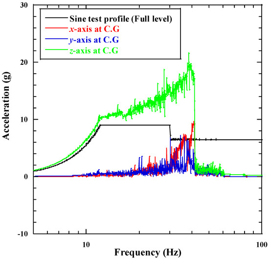
Figure 4.
Sine vibration test results of PLOVIS-II for z-axis.
Figure 5 shows the representative random vibration test results of PLOVIS-II during z-axis excitation. The test results indicated that the vibration response level in the higher-frequency region was significantly attenuated owing to the vibration energy dissipation induced by the slip and contact phenomena between the plastic components of the vibration isolator. The maximum acceleration of 5.12 grms of PLOVIS-II was measured for a random vibration test input of 15.40 grms. This value is 66% lower than 10.8 grms, the value obtained in a previous study using PLOVIS-I. The reason is that the combination of high-stiffness coil springs in PLOVIS-II effectively reduced the transmitted launch loads to the dummy cooler. In addition, although not described in this paper, the sine and random test results for the other test axes of PLOVIS-II showed similar trends to this test result [17].
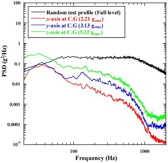
Figure 5.
Random vibration test results of PLOVIS-II for z-axis.
After performing the launch environment tests, a visual inspection confirmed that there was no mechanical failure of the vibration isolator, such as plastic deformation or fracture. These test and inspection results indicate that PLOVIS-II satisfies the structural safety of the cryogenic cooler and improves the vibration attenuation performance compared with conventional PLOVIS-I.
2.2.2. Micro-Vibration Measurement Test
To verify the effectiveness of PLOVIS-II in improving micro-jitter isolation performance compared to the conventional PLOVIS-I, a test was conducted using a dummy cooler on a micro-vibration measurement system with a 1 g compensation device. The force level induced by the dummy cooler in the main excitation axis (y-axis) of the cooler was 1.11 N at a main exciting frequency of 50 Hz. The test cases for the microvibration measurement conditions were as follows: (a) a condition to measure the microvibration level of the dummy cooler itself, which was rigidly fixed using a rigid bracket, and (b) a 0 g condition simulated using PLOVIS-II.
Figure 6 shows the test results for cases (a) and (b) for all axis responses during the main axis (y-axis) excitation of the dummy cooler. The maximum peak force of case (b) was observed to be 0.04 N at 50 Hz in the y-axis response, which is a significantly lower value than 1.11 N of case (a). This indicates that the microvibration level of the cooler was reduced by a factor of 27.5. Moreover, disturbances in the high-frequency range were effectively reduced because of the frequency-decoupling strategy used in the vibration isolator design.
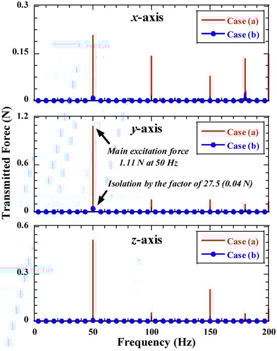
Figure 6.
Microvibration measurement test results along the excitation axis (y-axis) for the dummy cooler.
In this microvibration measurement test, a dummy cooler was used to evaluate the vibration isolation performance. However, it was observed that real coolers exhibited harmonic vibration characteristics depending on the excitation frequency of the cooler, as reported in previous studies [17]. Therefore, if harmonic vibrations are coupled with the elastic vibration modes of the structure-supporting cooler, they affect the ability of observation satellites to acquire high-resolution images. This implies that the dynamic characteristics of vibration isolators should be over a much wider frequency range.
3. Experimental Setup of the Force Transmissibility Test for PLOVIS-II
To verify the effectiveness of PLOVIS-II in terms of improving microvibration isolation, taking into account the harmonic vibration characteristics of the cooler, a force transmissibility test was conducted using a 4 kg dummy cooler with PLOVIS-II. The test setup mainly consisted of a noncontact vibration exciter and a microvibration measurement system, as shown in Figure 7. In this test, a noncontact vibration exciter was used to realize the multiaxis excitation of a dummy cooler, which is only possible with single-axis excitation (y-axis) using a linear motor, and to overcome the difficulty in realizing the actual boundary conditions of the cooler when using a contact vibration exciter. A noncontact vibration exciter consisting of a voice coil and permanent magnet was used to simulate the microvibration characteristics of a pulse-tube-type cooler. Here, a counter mass for the permanent magnet is used to prevent the center of gravity from shifting of the dummy cooler because the magnet is directly mounted on the cooler itself. The excitation force was amplified to 5 N using a power amplifier at an excitation frequency of 50–250 Hz generated by a function generator. These frequency ranges were established to evaluate the microvibration isolation performance compared with the harmonic vibration characteristics described above. An accelerometer was mounted at the C.G (Center of Gravity) of the dummy cooler to measure the excitation force. The disturbance force transmitted from the dummy cooler to the base plate was assessed using a microvibration measurement system, which incorporated three-axis load cells (MC15-3A-100, DACELL Co., Ltd., Cheongju., Republic of Korea., 4 units). A 1 g compensation device with a rubber-type wire was applied to the dummy cooler to simulate a 0 g condition where the dummy cooler remained in the nominal position of PLOVIS-II. Using the test setup, the force transmissibility (FT) of the cooler assembly with PLOVIS-II is expressed as follows:
where F0 is the measured excitation force of the cooler, and Ft is the force transmitted to the base plate.
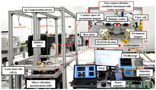
Figure 7.
Force transmissibility measurement test setup.
Figure 8 shows the sequential procedure followed during the force transmissibility measurement of the PLOVIS-II isolator. Following the experimental setup described in Figure 7, an excitation signal was generated by the function generator, amplified by the power amplifier, and applied to the dummy cooler through the non-contact vibration exciter. The excitation force and the transmitted force were simultaneously measured by the accelerometer and the microvibration measurement table, respectively. All signals were collected via the data acquisition system (DAQ) and subsequently processed to calculate the force transmissibility. This flowchart provides a clear visualization of the experimental steps undertaken to ensure the repeatability and reliability of the measurement process.
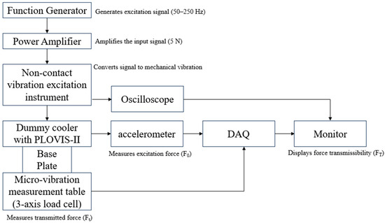
Figure 8.
Force transmissibility measurement flowchart.
Figure 9a–c show the cooler assembly configuration of the test setup with PLOVIS-II along the x-, y-, and z-axes. The x-axis test was performed using an additional bracket that allowed the cooler to be excited along the x-axis. The test configuration for PLOVIS-I was identical to that of PLOVIS-II.
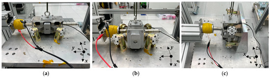
Figure 9.
Test configuration of the dummy cooler with PLOVIS-II ((a) y-axis, (b) z-axis, and (c) x-axis).
4. Force Transmissibility Test Results of PLOVIS-II
The basic characteristics of force transmissibility for PLOVIS-II were derived using the test setup described above. A position sensitivity test was conducted to evaluate the microvibration-isolation performance when the dummy cooler was shifted from the nominal position of the vibration isolator. The vibration isolator exhibited absolute isolation performance when the dummy cooler remained in the nominal position; this guaranteed vibration isolation performance. However, if the cooler shifts from its nominal position owing to an unexpected misalignment or thermal deformation of the heat pipes integrated into the cooler to transfer heat from the cooler, there is a possibility that the vibration isolation performance can be degraded. In practice, it is difficult to precisely align a cooler integrated with a heat pipe and transfer line at the nominal position of the vibration isolator, which is necessary for obtaining optimal vibration isolation performance. Therefore, to reduce the potential risk to system reliability, we considered using an isolation system with less position-sensitive characteristics. The alignment requirements of the IR sensor module integration and heat pipe for maintaining the desired vibration isolation performance were also derived from the test.
In the test, a forced translational displacement was applied to shift the cooler position along the representative gravity axis (x-axis). The test was conducted by shifting the dummy cooler in 0.75 mm and 1.5 mm increments, because it was difficult to perform the test with increments smaller than 0.75 mm due to the limitations of the test setup. In addition, the vibration isolation performance variation of the position sensitivity was clearly distinguishable, even with 0.75 mm increments. The test cases for measuring the force transmissibility of the cooler assembly with PLOVIS-I and PLOVIS-II were defined as follows: (A) under a simulated 0 g condition; (B) and (C) enforced displacements of 0.75 and 1.5 mm, respectively, applied to the cooler; (D) under a 1 g condition, where a static force of 37.24 N was applied along the gravitational direction as a result of the cooler’s mass. In case (A), the dummy cooler was positioned at the nominal position of the isolator using a 1 g compensation device, where the desired vibration isolation performance could be guaranteed, as shown in Figure 10a. Figure 10b shows a representative configuration of Case (C), in which the cooler was shifted from the nominal position of the vibration isolator to simulate the conditions in Cases (B) and (C). It should be noted that the tolerances for the cooler alignment of PLOVIS-I and PLOVIS-II were 1.5 and 1.2 mm, respectively, resulting in different support conditions for Case (C). This means that the dummy cooler with PLOVIS-II is supported by a moving plate with a 0.3 mm compressed high-stiffness coil spring, unlike PLOVIS-I, which contacts a displacement limiter. Case (D) represented an unexpected condition for on-orbit operation; however, it was included to qualitatively assess the microvibration isolation performance when the dummy cooler deviated from the low-stiffness range for the reasons previously mentioned. In such a case, without a 1 g compensation device, the coil springs with low stiffness used in PLOVIS-I and PLOVIS-II were extended and compressed by the weight of the cooler assembly. However, the two vibration isolators have different mechanical support configurations. For example, as shown in Figure 10c, a moving plate combined with high-stiffness coil springs supports the dummy cooler with PLOVIS-II under the 1 g condition. However, the cooler with PLOVIS-I is in direct contact with the displacement limiter integrated into the support structure, as shown in Figure 10d.
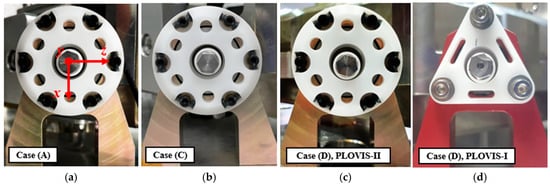
Figure 10.
Cooler position for each case ((a) Case (A) of PLOVIS-II, (b) Case (C) of PLOVIS-II, (c) Case (D) of PLOVIS-II, and (d) Case (D) of PLOVIS-I).
Figure 11 shows the test results for Case (A) for the x-, y-, and z-axes. As can be seen, both vibration isolators have almost the same force transmissibility characteristics under the 0 g condition because both vibration isolators support the dummy cooler with the same low-stiffness configuration. The force transmissibility of PLOVIS-I and PLOVIS-II at the main excitation frequency of the cooler of 50 Hz were less than 0.05 for all axes, indicating that the microvibration level of 5 N for the dummy cooler was remarkably reduced by a factor of 25. This value closely corresponds to the value (23) predicted from the transmissibility curve of the isolation system, which has a natural frequency of 8 Hz, derived using a one-degree-of-freedom mathematical model [17]. Moreover, because of the frequency-decoupling strategy adopted in the vibration isolator design, the disturbances as well as force transmissibility were effectively reduced in the high-frequency region on all the axes.
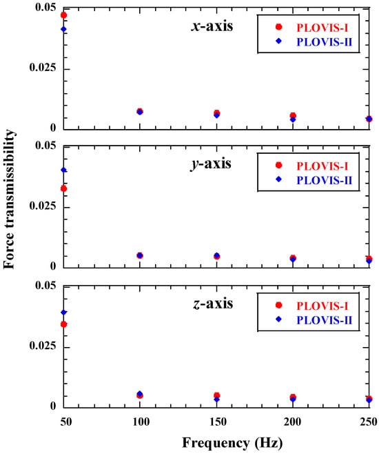
Figure 11.
Force transmissibility measurement test results for Case (A).
Figure 12a and Figure 12b show the position sensitivity test results for Cases (B) and (C) along the x-, y-, and z-axes, respectively. The test results for the force transmissibility test from 50 to 250 Hz showed that the force transmissibility increased when the cooler assembly shifted from the nominally aligned position of the vibration isolator. Both vibration isolators showed almost the same test results in Case (A) because they had similar support conditions for the low-stiffness coil springs. However, in Case (C), the force transmissibility of PLOVIS-II was approximately 1.3 times lower than that of PLOVIS-I in all excitation frequency ranges because of the different support conditions. This minimizes the high-frequency harmonic disturbances associated with the coupling to the structural modes of the cooler assembly, leading to an improvement in vibration isolation performance. This indicates that the PLOVIS-II designs supported by high-stiffness springs exhibited better microvibration reduction in terms of position sensitivity.
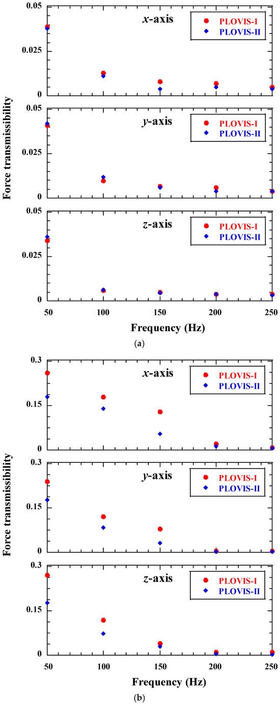
Figure 12.
Force transmissibility measurement test results ((a) Case (B) and (b) Case (C)).
Figure 13 shows the test results for Case (D) for the x-, y-, and z-axes. The force transmissibility characteristic of PLOVIS-II for all axes under the 1 g condition was more than 1.6 times lower than that of PLOVIS-I in all frequency ranges. This is because the cooler was supported by a moving plate with high-stiffness coil springs, unlike PLOVIS-I, where microvibrations from the cooler were directly transmitted to the base plate via the support structure.
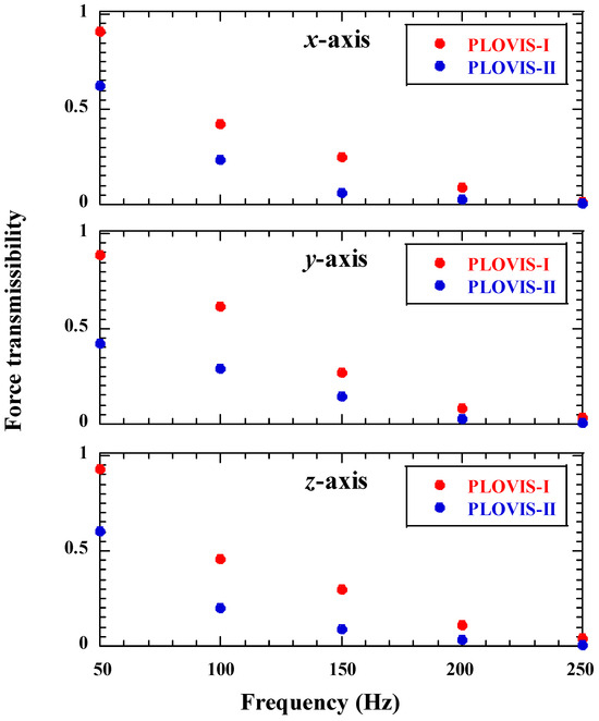
Figure 13.
Force transmissibility measurement test results for Case (D).
These test results indicate that PLOVIS-II has a lower tolerance for cooler alignment compared to PLOVIS-I. Further, unlike PLOVIS-I, PLOVIS-II has unsusceptible position sensitivity, as intended by its design, even when operated under severe and unexpected conditions during on-orbit operation. Therefore, the proposed PLOVIS-II is effective in relaxing the strict heat pipe and infrared detector alignment requirements, which is desirable for reducing potential risks when considering system reliability.
5. Conclusions
This study involved the design and validation testing of PLOVIS-II, a passive vibration isolator with a dual-coil spring configuration, to assess its enhancement in position sensitivity and reduction in launch vibration compared to the conventional PLOVIS-I. In addition, to measure the basic characteristics of force transmissibility for PLOVIS-II, a test setup was presented to measure the force transmissibility of the isolator along each axis using a voice-coil-type non-contact vibration excitation instrument. The results of the force transmissibility tests of PLOVIS-I and PLOVIS-II under simulated 0 g conditions showed a significant reduction in microvibration owing to the frequency decoupling strategy. Position sensitivity tests demonstrated that PLOVIS-II was less sensitive than PLOVIS-I to the alignment position of the vibration isolator, because the PLOVIS-II designs were supported by high-stiffness springs. In addition, this design minimizes the high-frequency harmonic disturbances caused by coupling with the structural modes in the cooler assembly.
Author Contributions
Conceptualization, H.-U.O.; Validation, Y.-H.P., M.-S.J., H.-Y.K. and H.-U.O.; Formal analysis, Y.-H.P.; Investigation, Y.-H.P., M.-S.J., H.-Y.K. and H.-U.O.; Data curation, Y.-H.P.; Writing—original draft, Y.-H.P.; Writing—review & editing, M.-S.J., H.-Y.K. and H.-U.O.; Supervision, H.-U.O.; Project administration, M.-S.J. All authors have read and agreed to the published version of the manuscript.
Funding
This research was funded by Hanwha Systems, Republic of Korea (grant number: CDE-21046).
Data Availability Statement
Data used to support the findings of this study are available from the corresponding author upon request.
Conflicts of Interest
Authors Yeon-Hyeok Park and Hyun-Ung Oh were employed by the company STEPLab. Ltd. Authors Mun-Shin Jo and Hoon-Young Kim were employed by the company Mechatronics Groups, Hanwha Systems. All authors declare that the research was conducted in the absence of any commercial or financial relationships that could be construed as a potential conflict of interest.
References
- Veprik, A.M.; Babitsky, V.I.; Pundak, N.; Riabzev, S.V. Vibration Control of Linear Split Stirling Cryogenic Cooler for Airborne Infrared Application. Shock Vib. 2000, 7, 363–379. [Google Scholar] [CrossRef]
- Gilmore, D.G. Spacecraft Thermal Control Handbook: Fundamental Technologies, 2nd ed.; The Aerospace Press: Chantilly, VA, USA, 2002. [Google Scholar]
- Radebaugh, R. Pulse Tube Cryocoolers for Cooling Infrared Sensors. In Proceedings of the Infrared Technology and Applications XXVI, San Diego, CA, USA, 30 July–4 August 2000; Volume 4130, pp. 363–379. [Google Scholar] [CrossRef]
- Ross, R.G. Cryocooler Reliability and Redundancy Considerations for Long-Life Space Missions. In Cryocoolers; Ross, R.G., Ed.; Springer: Berlin/Heidelberg, Germany, 2002; Volume 11. [Google Scholar] [CrossRef]
- Ellis, M.J.; Luong, T.T.; Shaw, L.; Murphy, J.; Moody, E.; Lisiecki, A.; Kirkconnell, C. Development of a Miniature Cryocooler System for Cubesats. Cryocoolers 2014, 18, 329–339. [Google Scholar]
- Cobb, R.G.; Sullivan, J.M.; Das, A.; Davis, L.P.; Hyde, T.T.; Davis, T.; Rahman, Z.H.; Spanos, J.T. Vibration Isolation and Suppression System for Precision Payloads in Space. Smart Mater. Struct. 1999, 8, 798–812. [Google Scholar] [CrossRef]
- Riabzev, S.V.; Veprik, A.M.; Vilenchik, H.S.; Pundak, N.; Castiel, E. Vibration-Free Stirling Cryocooler for High Definition Microscopy. Cryogenics 2009, 49, 707–713. [Google Scholar] [CrossRef]
- Kamesh, D.; Pandiyan, R.; Ghosal, A. Passive Vibration Isolation of Reaction Wheel Disturbances Using a Low Frequency Flexible Space Platform. J. Sound Vib. 2012, 331, 1310–1330. [Google Scholar] [CrossRef]
- Takei, Y.; Yasuda, S.; Ishimura, K.; Iwata, N.; Okamoto, A.; Sato, Y.; Ogawa, M.; Sawada, M.; Kawano, T.; Obara, S.; et al. Vibration Isolation System for Cryocoolers of Soft X-ray Spectrometer (SXS) Onboard ASTRO-H (Hitomi). In Proceedings of the Space Telescopes and Instrumentation 2016: Ultraviolet to Gamma Ray, Edinburgh, UK, 26 June–1 July 2016; Volume 9905. [Google Scholar]
- Takuma, S.; Sakai, S. Performance of Contractless Micro Vibration Isolator Using Flux Pinning Effect. Jpn. Soc. Aeronaut. Space Sci. ISTS 2017, 20, 1–8. [Google Scholar]
- Yang, J.; Huang, C.; Wang, Y.; Li, K. Design and Testing of a Novel Passive Isolator for a Space Optical Payload. J. Harbin Inst. Technol. 2018, 25, 85–96. [Google Scholar]
- Robinson, D.; Tonn, S. Mechanical Aspects of the Thermal Infrared System (TIRS) on Landsat 8. In Proceedings of the 2015 IEEE Aerospace Conference, Big Sky, MT, USA, 7–14 March 2015; pp. 1–10. [Google Scholar] [CrossRef]
- Kwon, S.C.; Jeon, S.H.; Oh, H.U. Performance Investigation of a Novel Pseudoelastic SMA Mesh Washer Gear Wheel with Micro-jitter Attenuation Capability. Smart Mater. Struct. 2016, 25, 055004. [Google Scholar] [CrossRef]
- Kwon, S.-C.; Jo, M.-S.; Ko, D.-H.; Oh, H.-U. Viscoelastic Multilayered Blade-Type Passive Vibration Isolation System for a Spaceborne Cryogenic Cooler. Cryogenics 2020, 105, 102982. [Google Scholar] [CrossRef]
- Oh, H.-U.; Lee, K.-J.; Jo, M.-S. A Passive Launch and On-Orbit Vibration System for the Spaceborne Cryocooler. Aerosp. Sci. Technol. 2013, 28, 324–331. [Google Scholar] [CrossRef]
- Available online: https://directory.eoportal.org/web/eoportal/satellite-missions/k/kompsat-3a (accessed on 17 December 2024).
- Park, Y.-H.; Jo, M.-S.; Lee, E.-S.; Oh, H.-U. Performance Enhancement of Spaceborne Cooler Passive Launch and On-Orbit Vibration Isolation System. Int. J. Aerosp. Eng. 2020, 2020, 6017957. [Google Scholar] [CrossRef]
- Available online: https://www.aquariusplastics.co.uk/ (accessed on 17 December 2024).
Disclaimer/Publisher’s Note: The statements, opinions and data contained in all publications are solely those of the individual author(s) and contributor(s) and not of MDPI and/or the editor(s). MDPI and/or the editor(s) disclaim responsibility for any injury to people or property resulting from any ideas, methods, instructions or products referred to in the content. |
© 2025 by the authors. Licensee MDPI, Basel, Switzerland. This article is an open access article distributed under the terms and conditions of the Creative Commons Attribution (CC BY) license (https://creativecommons.org/licenses/by/4.0/).