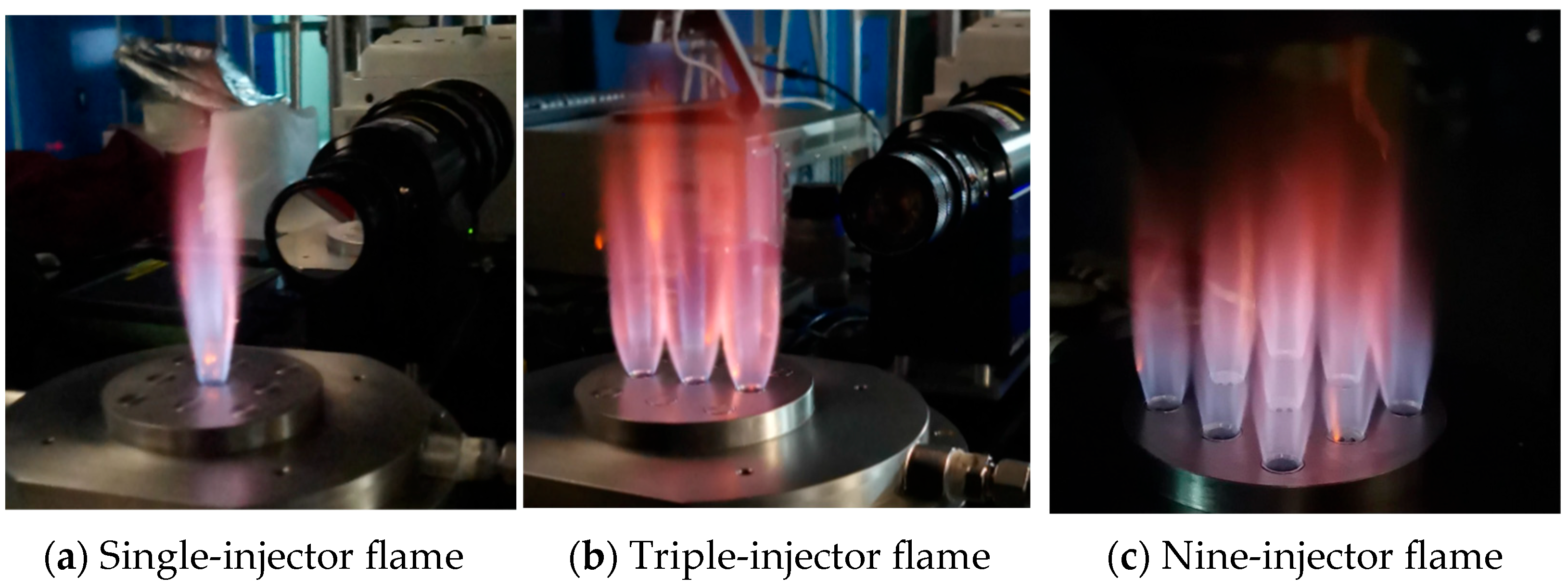
The stable pure hydrogen flame images for single, three, and nine injectors in an open environment are shown in
Figure 2. Both single and multiple flames exhibit inner and outer flame layers. The inner and base regions of the flame appear blue, while the outer region is red. The red light is emitted by water molecules at high temperatures. The layered appearance of the flame indicates different flow structures or physical mechanisms in the inner and outer layers. Previous studies have shown that the inner layer is a partially premixed flame dominated by premixing, while the outer layer is a diffusion flame dominated by diffusion [
9]. This is because some hydrogen from the side walls of the injection tube is entrained into the wake region behind the bluff body, forming a well-mixed premixed flame, while the remaining hydrogen is carried into the external boundary layer by the surrounding airflow, resulting in a diffusion flame.
The premixed flame is sensitive to velocity fluctuations, meaning that small upstream disturbances, such as vortex shedding from the bluff body and injection tube, can cause significant fluctuations in the flame front. The area of the flame front is positively correlated with the heat release rate, so premixed flames are more likely to induce heat release rate fluctuations in turbulent combustion systems, leading to thermoacoustic oscillations. In contrast, diffusion flames [
28,
29] have stable and clear flame fronts, and their combustion process might mainly depend on the fluctuations in the mass combustion rate, which are small under stable conditions, making them more stable.
3.1. Single-Injector Flames
The combustion characteristics of pure hydrogen micro-mixing flames are influenced by parameters such as the equivalence ratio and total gas flow rate. At a certain flow rate, changes in the equivalence ratio alter the flame propagation speed and temperature, thus changing the flame height and expansion. Additionally, the short mixing distance between hydrogen and air in the burner injectors, combined with the mixed characteristics of the flame structure, means that changes in the overall equivalence ratio can affect the mixing characteristics of the fuel and flame, potentially influencing the detailed flame structure.
3.1.1. Effect of Mass Flow Rate
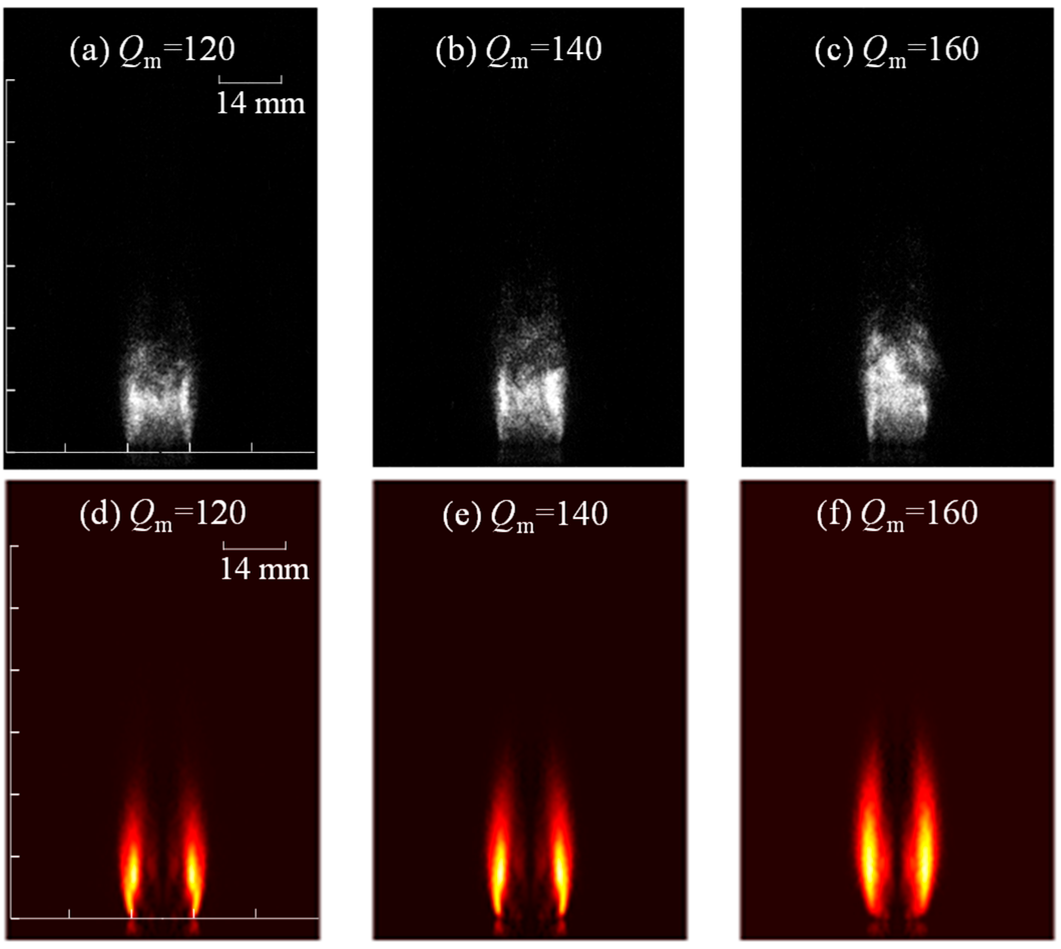
Figure 3 shows the effect of the total gas mass flow rate on instantaneous and average flame morphology at an equivalence ratio of 0.4. The upper row of
Figure 3 displays instantaneous OH* flame images, while the lower row presents the Abel inverse results derived from the time-averaged data of 120 instantaneous OH* flame images. Despite the slight asymmetry in the instantaneous images due to turbulence-induced flame wrinkling, the time-averaged flames exhibit good symmetry, giving the rationality of the Abel inverse transformation. At relatively low mass flow rates, such as 120 and 160 SLPM, the flame still exhibits a clear double-layer structure. However, as the flow rate increases to 200 and 240 SLPM, the double-layer flame structure remains but becomes increasingly blurred. The outer flame can be distinguished from the base region of the flame, while the inner flame is mainly present downstream of the bluff body and extends over a larger area. This trend is likely due to increased airflow enhancing the mixing of fuel and air, increasing the premixed degree of the flame and intensifying the premixed flame downstream of the bluff body. Additionally, with a constant overall equivalence ratio, increased air flow leads to higher mainstream velocity, pushing the flame further downstream and elongating flame length.
The image processing methods shown in
Figure 4 and
Figure 5 are the same as those shown in
Figure 3. By comparing
Figure 3 and
Figure 4, it can be seen that increasing the total mass flow rate within a certain range has a similar effect on the flame structure as decreasing the equivalence ratio. Reducing the equivalence ratio from 0.40 to 0.35 at the same mass flow rate results in shorter flame heights and a higher intensity of the inner premixed flame, indicating a weaker outer diffusion flame and reduced flame stability.
Figure 5 shows the flame chemiluminescence images at an equivalence ratio of 0.25 and flow rates of 120, 140, and 160 SLPM when continuing to reduce the equivalence ratio while adjusting the total mass flow rate. At low equivalence ratios, the flame exhibits only a single-layer structure. This is because the fuel flow rate is very low at this time, and the momentum ratio between fuel and air is also very low, resulting in a small penetration depth of hydrogen and a poor mixing effect. Hydrogen cannot easily enter the downstream region of the bluff body, thus only forming a single-layer diffusion flame structure at the outer shear layer.
3.1.2. Effect of Equivalence Ratio
At a typical flow rate of 170 SLPM, the effect of the equivalence ratio on the pure hydrogen flame state was investigated. Generally, as the equivalence ratio increases, the flame height increases and expands outward. This is due to the higher fuel flow rate, which requires longer mixing and combustion times for the fuel and air. Additionally, a higher equivalence ratio leads to increased flame temperature, causing the flame to expand.
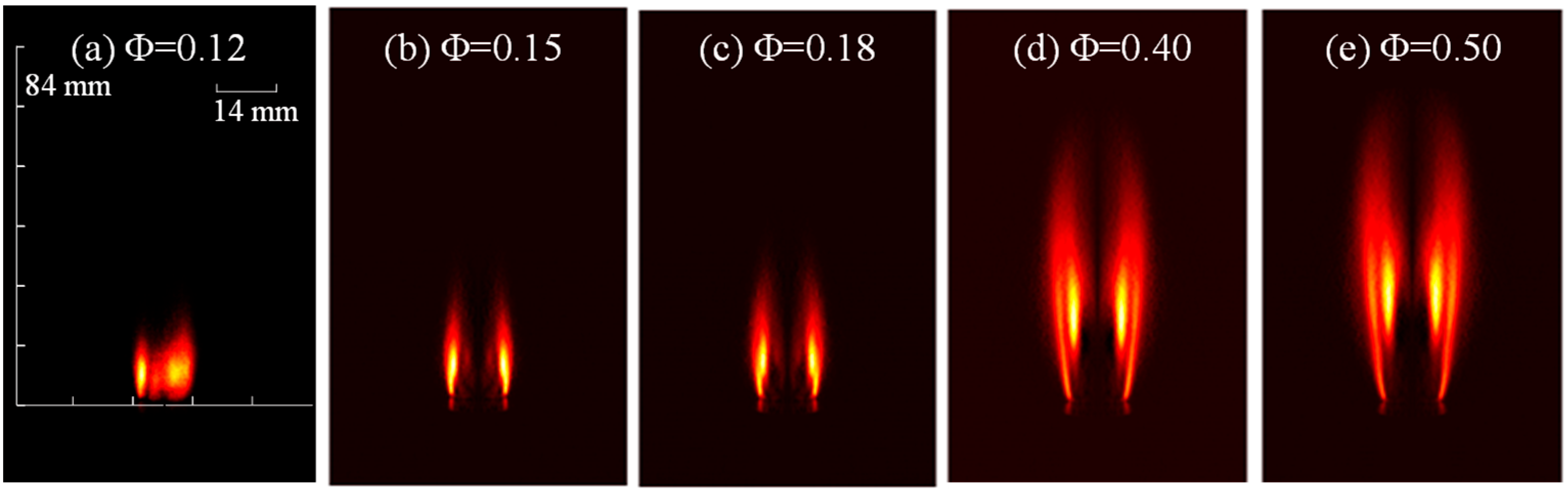
As shown in
Figure 6, the flame structure changes significantly with the equivalence ratio. At an extremely low equivalence ratio of 0.12, near the blow-out limit, a complete flame cannot form downstream of the hydrogen injection port, and the single-injector flame fails to maintain stable combustion, appearing irregular. Increasing the equivalence ratio to 0.15 stabilizes the combustion, while the flame height remains low and a single-layer structure. This is because, at very low equivalence ratios, the weak hydrogen jet is primarily entrained by the main airflow and does not penetrate the wake region behind the bluff body, resulting in a single-layer flame on the outside. As the equivalence ratio increases to 0.18, the flame size grows, and a weak stratification begins to appear. When the equivalence ratio reaches 0.40, the flame structure undergoes a significant transformation, exhibiting a distinct double-layer structure where the inner flame has a higher heat release intensity compared to the outer flame. This indicates that the combustion intensity of the inner flame increases with the hydrogen flow rate, forming a region of maximum combustion intensity downstream of the bluff body.
3.1.3. Effect of Air Injector Exit Angle
The exit angle of the air injector can significantly influence the flame morphology. For single-injector flames, changing the exit angle can cause the outer flame to expand, thereby affecting the overall flame structure.
Figure 7 demonstrates the effect of the injector outlet angle, with and without a 45° chamfer at the injector exit, on the heat release structure of flames, at a fixed equivalence ratio of 0.45 and various mass flow rates.
Figure 7a–d present the results for a 1 mm chamfer, while
Figure 7e–h show the results for a straight exit. As the total flow rate increases from 120 to 240 SLPM, the outer flame front exhibits a more pronounced V-shape when the exit has a chamfer, indicating a larger angle between the outer flame and the central axis. Furthermore, the flame structure with an outlet chamfer consistently maintains a clear double-layer structure across all mass flow conditions, whereas the double-layer structure becomes less distinct at higher flow rates without a chamfer. This phenomenon can be attributed to the change in flame angle. The angled exit causes the outflowing gas to follow the chamfer, forming an angle with the main flow. Due to the lower velocity in the outer shear layer, flame stabilization occurs within this layer, leading to the formation of a specific angle on the outer flame surface. This increased flame angle reduces the interaction between the outer and inner flames at high flow rates, thereby maintaining a stable flame structure across a wide range of operating conditions.
Furthermore, this study investigated the impact of the injector exit cone angle on the flame structure by varying the overall equivalence ratio under various total mass flow rates. The results are shown in
Figure 8. It is observed that for cases without a cone angle at the exit (
Figure 8e–h), the flame does not exhibit a stratified structure due to high flow velocity and effective mixing at a low equivalence ratio (ϕ = 0.30). However, at higher equivalence ratios, the central premixed flame dominates the combustion, with the outer diffusion flame concentrated in the lower section. In contrast, for cases with a cone angle at the exit (
Figure 8a–d), the flame always displays a distinct double-layer structure across all equivalence ratios. This further confirms that the presence of the cone angle alters the interaction between the outer and inner flames, enabling a stable heat release structure over a wide range of operating conditions.
These results demonstrate that even minor structural modifications in the injector can substantially influence the flame structure and combustion characteristics, offering valuable insights for injector optimization. Building on this foundation, we plan to extend our investigation to multiple-injector flames, leveraging the findings from our single-injector studies.
3.2. Angled Multiple-Injector Hydrogen Flames
After examining the single-injector flame characteristics concerning equivalence ratio and flow rate, this study then investigated the pure hydrogen micro-premixed multiple-flame characteristics using a three-injector configuration with chamfered exits. Given that the Abel transformation applies to symmetric flames, such as those from a single injector, it was not employed for analyzing the flame structure of multiple-injector configurations. Instead, OH chemiluminescence images were directly captured to observe the flame morphology and the effects of flame interactions.
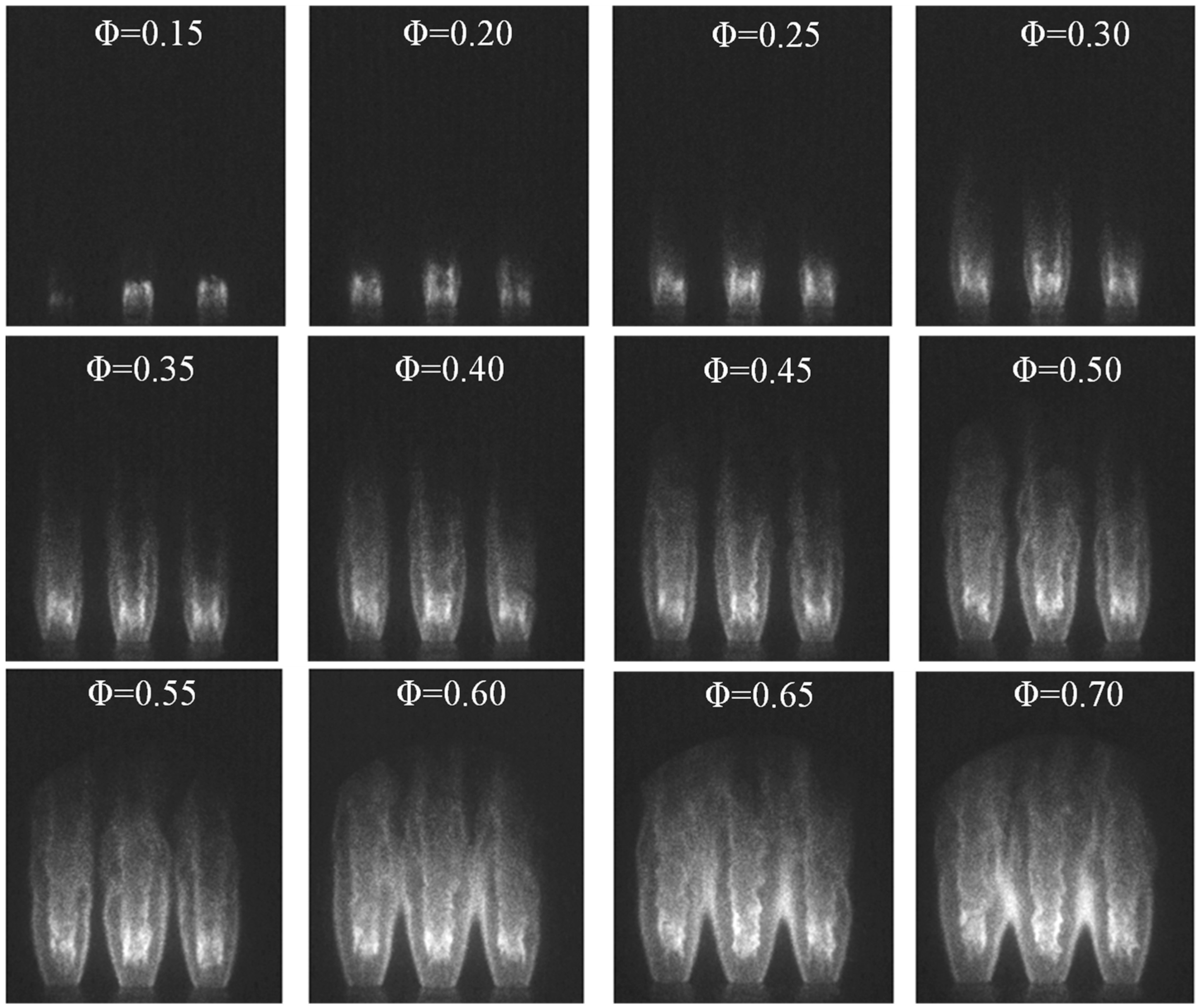
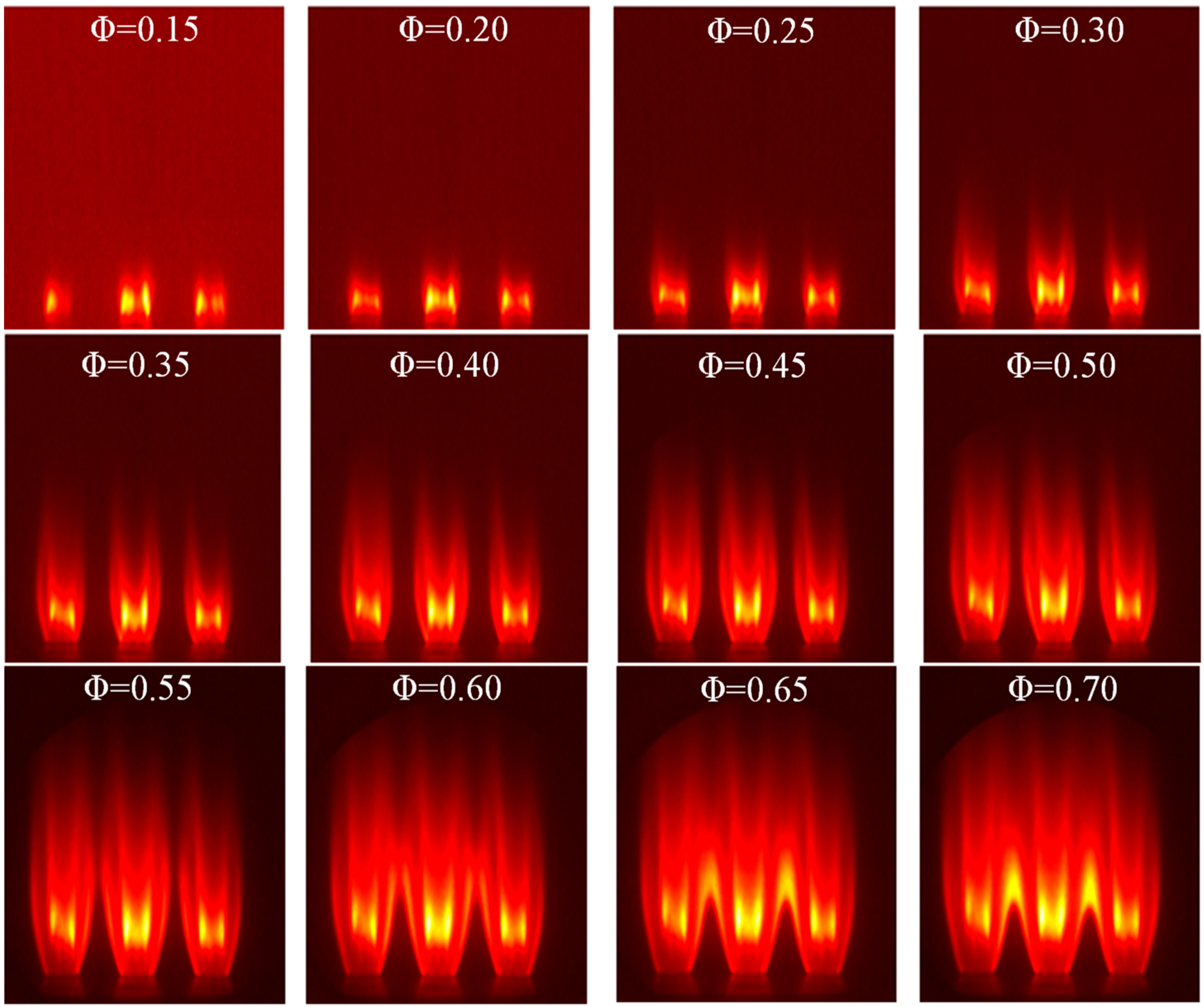
Figure 9 illustrates the influence of equivalence ratio variation on transient OH* distribution patterns in tri-flame configurations under a constant total flow rate of 240 SLPM. The experimental observations reveal a progressive enhancement in chemiluminescent emission intensity and axial flame extension with ascending equivalence ratios, aligning with the fundamental characteristics documented in single-injector combustion systems. At Φ = 0.15, the combustion system exhibits flame structural instability characterized by asymmetric heat release distribution, where the leftmost flame demonstrates substantially attenuated chemiluminescence relative to its counterparts, suggesting localized combustion quenching. When Φ reaches 0.20, complete flame ignition is achieved across all injectors, while their heights are uneven, with the central flame standing taller. Transitioning beyond Φ = 0.25 induces flame stabilization accompanied by distinct dual-layer OH* stratification. Progressive equivalence ratio augmentation facilitates the simultaneous elongation of both inner and outer flame fronts, accompanied by intensified wrinkling in the inner flame boundary. This phenomenon directly reflects an enhanced heat release rate of the flame.
Instantaneous images also reveal that as the equivalence ratio increases to 0.60, interactions occur between the outer flame surfaces of adjacent flames. This interaction does not significantly alter the overall structure of the flames, and the outer layers of the three flames maintain relative independence. When the equivalence ratio increases above 0.65, the interaction between adjacent flames becomes significantly stronger. The outer flames undergo noticeable deformation and bending under the interaction, and a stronger flame chemiluminescence intensity is formed in the interaction region.
The time-averaged flame images are presented in
Figure 10, corresponding to the instantaneous flame snapshots shown in
Figure 9. The mean flame structures reveal distinct combustion characteristics under different equivalence ratios. At an ultra-lean condition of Φ = 0.15, the triple-flame configuration demonstrates significant instability with a non-uniform heat release distribution. Only the central flame maintains a complete circumferential structure, while localized flame extinction occurs intermittently in both side flames. This phenomenon arises from the combined effects of insufficient fuel concentration and spatial inhomogeneity in flow distribution, causing local equivalence ratios downstream of certain fuel injection ports to fall below the lean blow-off limit.
When increasing the equivalence ratio to Φ = 0.20, complete ignition of all three flames is achieved, albeit with notably weak combustion intensity manifested through shortened flame lengths. The transition to Φ = 0.30 marks improved flame stability, though flame structure disparities emerge due to the non-uniformity of air distribution and differential boundary conditions between central and side flames. Specifically, the central flame develops a more symmetric heat release pattern compared to its lateral counterparts.
Further enhancement to Φ = 0.60 induces morphological changes in the flame system, where initial weak interactions between adjacent flames are observed through outer flame surface contact while maintaining relative independence. At Φ = 0.65, intensified flame–flame interactions lead to the merging of outer reaction zones between neighboring flames, forming distinctive conical flame structures with localized high heat release rates at the flame outer layer merging points. This interaction pattern progressively intensifies with increasing equivalence ratios, as evidenced by the strengthened heat release intensity at the conical flame tips between adjacent injectors in instantaneous flame images.
The reasons for the increased interaction between flames at higher equivalence ratios include the following: (1) higher combustion temperatures leading to greater thermal expansion, and increased radial flame size; (2) higher fuel flow rates leading to longer fuel residence times and axial flame elongation; (3) and the simultaneous increase in radial and axial flame sizes, making the probability of interaction between adjacent flames greater and the interaction more significant. The interaction between flames increases the flow disturbance in the region, enhancing fuel–air mixing and increasing the heat release rate.
3.3. Flow Field of Pure Hydrogen Micro-Mixing Flames
The flow field structure of single- and multiple-injector flames was measured at a typical condition of an equivalence ratio of 0.5 and a total flow rate of 80 SLPM.
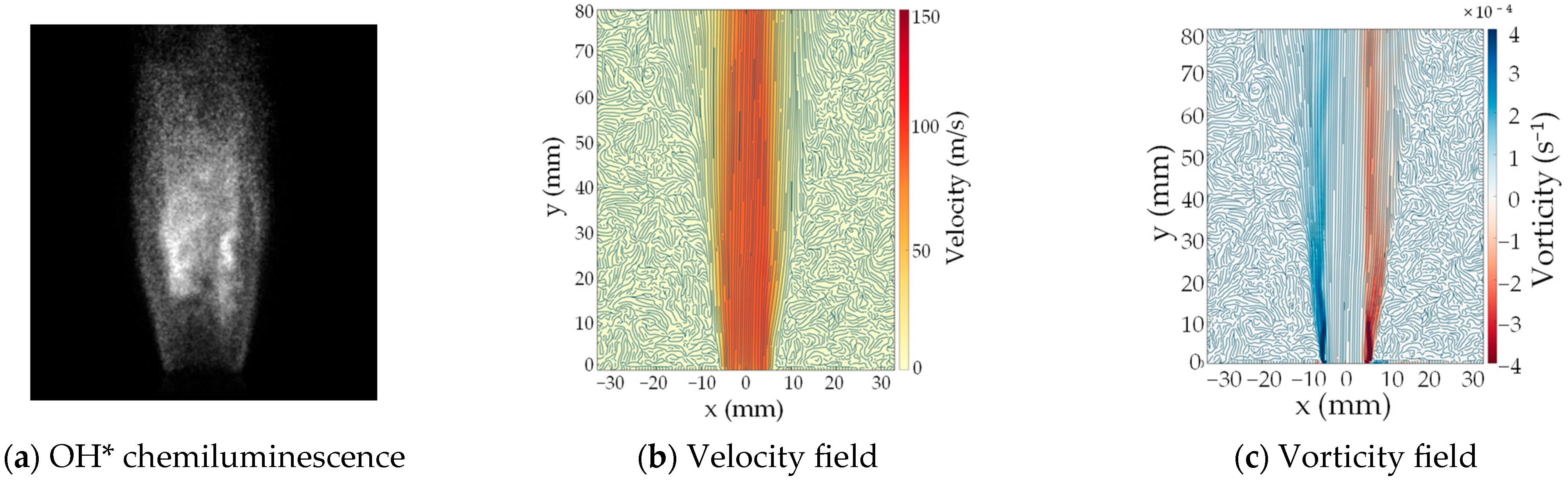
Figure 11 shows the OH* chemiluminescence signal, streamlined flow field, and vorticity field for a single injector.
The flow field results show that the velocity distribution at the injector exit exhibits jet-flow characteristics, with the center velocity exceeding 100 m/s and being almost parallel to the longitudinal axis, indicating good uniformity. However, there is a significant velocity gradient between the flame and the surrounding region because the surrounding region is an open space with very low velocity. The outermost region does not show effective streamlines because the PIV particles did not spread to this area. Processing the velocity field can yield the vorticity field, as shown in subfigure (c) of
Figure 11. It can be observed that the structure of the vorticity field bears a resemblance to the structure of the flame heat release, indicating a stratified phenomenon in the vorticity field as well. In the lower half of the flame, the outer layer corresponds to stronger vorticity, suggesting a more pronounced shearing effect in this region. The flame structure also reveals that the outer flame surface predominates in this area. The inner flame develops from the base downstream but only forms a relatively stable flame front after a certain distance downstream of the outlet. The strong shear region of the inner flame is located at the interface between the inner and outer layers and gradually intensifies to form an increasingly strong inner shear layer downstream of the injector, leading to a relatively enhanced vorticity distribution.
The flow field, instantaneous chemiluminescence, and vorticity field of a three-injector flame are shown in
Figure 12. Due to the relatively low flow rate, there is no significant interaction between adjacent flames. The flow field also shows that the velocity between adjacent flames is low, and the flow direction is consistent with the main flow, indicating no cross-interaction between the flame fronts. The vorticity field shows that the shear layers of adjacent flame fronts do not interact, with the outer shear layers remaining separate. Near the injector exit, flow disturbances exist due to the sudden expansion of the injector exit cross-section, distorting the streamlines in this region.
By comparing the streamline diagrams of the flame and flow field shown in
Figure 11 and
Figure 12, it can be observed that for a single injector, the streamlines diverge downstream of the flame due to the lack of confinement, forming a V-shaped pattern. In contrast, for the three-injector configuration, the divergence of the streamlines downstream is inhibited by the adjacent flame jets, maintaining a jet state aligned with the main flow direction. Comparing the heat release rate images reveals that the lateral dimensions of the central flame in the multi-injector configuration are larger than those of the single-injector flame. There are two possible reasons for this: first, the simultaneous combustion of the three injectors creates a high-temperature environment around the central flame, leading to overall gas expansion and an increase in size; second, although the outer flame surfaces of the three injectors do not exhibit a significant interaction, the potential influence of the flow may cause the outer flame surfaces in the mid-to-downstream region to experience shear from adjacent flame surfaces, resulting in a slight outward expansion of the flame.
In summary, this work presents an experimental investigation of the matrix micro-mixing pure hydrogen flame under stable conditions, providing us with a whole picture of the single- and triple-flame properties. Fundamentally, flame stabilization mechanisms of the micro-mixing injector share similarities with prior structures documented in prior studies [
5,
25]. The fuel mixes with the air over a very short distance and then flows into the combustion zone. The principal innovation of this work lies in the strategic implementation of a miniature bluff body geometry that establishes a stabilized premixed flame core. This novel configuration achieves dual stabilization benefits: the central premixed flame serves as a continuous ignition source while the surrounding diffusion flame structure enhances the combustion stability.
Future investigations will focus on optimizing the injector through integrated analysis of combustion instability modes and NOx emissions. This will involve establishing a confined flame using a quartz tube. When the burner is confined, the temperature of the gas surrounding the flame increases, which can affect flame interaction and potentially enhance flame speed, thereby improving the mixing effects near the outer flame layer. The premixing process between hydrogen and air occurs within the injector and is associated with the inner flame layer. While the impact of confinement on the premixing process is expected to be minimal, it still requires an insightful investigation. Particular emphasis will be given to flame–acoustic interaction mapping under transient operating conditions and the development of multi-pollutant control strategies for both pure hydrogen and hydrogen–ammonia hybrid fuels. These critical research advances represent converging priorities for both the industrial and academic communities.


