Abstract
This article reviews the physical and chemical mechanisms associated with unsteady swirl-stabilized partially or fully lean premixed combustion. The processes of flame stabilization, mode conversion, swirl number oscillation, equivalence ratio oscillation, and vortex rollup are described. The key challenges associated with flow-flame dynamics for several sources of perturbations are presented and discussed. The Rayleigh criterion is discussed. This article summarizes the scientific knowledge gained on swirling flames dynamics in terms of modeling, theoretical analysis, and transient measurements with advanced diagnostics. The following are specifically documented: (i) the effect of the swirler on swirling flames; (ii) the analytical results, computational modeling, and experimental measurements of swirling flame dynamics; (iii) the influence of flow features on flame response of swirling flames for combustion instabilities studies; and (iv) the identification and description of the combustion dynamics mechanisms responsible for swirl-stabilized combustion instabilities. Relevant elements from the literature in this context for hydrogen fuel are included.
Keywords:
flame; decarbonization; clean combustion; sustainability; hydrogen; premixed; stabilization; mechanisms; instability; swirl 1. Introduction
1.1. Context, Applications, and Challenges
Swirl-stabilized combustion is widely used in aeronautics. Accordingly, any combustor’s improvement can have a tremendous impact in terms of fuel burn reduction and pollutant emissions mitigation. Annular combustors include a set of injectors equipped with swirlers distributed in the annular direction where each injector stabilizes a flame. Because of the challenges relevant to design, swirling flows have been widely studied under both non-reacting and reacting conditions.
Swirl is utilized in reacting flows to ensure the robust stabilization of the flame because swirl induces an inner recirculation zone of high temperature and a low flow velocity region between the burnt gases and the fresh reactant mixture, where necessary kinematic conditions are met for the fully premixed flame. This generates short flames. The location of the annular combustor within the engine is central, between the exit of the high pressure compressor and the inlet of the high pressure turbine. The combustor converts the energy content of the fuel into thermal energy and then kinetic energy of the flow prior reaching the high-pressure turbine. It delivers high power within a compact and confined volume.
The reduction in emissions to mitigate the environmental impact of combustion systems is a priority [1], including and especially for aviation [2,3]. Towards this goal and better combustion systems to address the climate change challenge, the coupling between the flow dynamics (and implicitly the geometry), the combustion processes, and the acoustics must be studied. It implies different types of flow perturbations (waves and flow patterns) possibly leading to combustion instabilities. This is an aspect to consider for the design of future clean premixed combustion systems. The description, identification, modeling and prediction of combustion instabilities and associated mechanisms in laboratory-scale and jet engine configurations is thus important. Several aspects of those challenges are reviewed in this article. The control of combustion instabilities and ignition processes are let out of the scope of this review article.
1.2. Previous Reviews, Motivation and Scope of This Article
Research on swirling flames dynamics and combustion instabilities in swirl-stabilized combustion systems has been the subject of several monographs and review articles published since the 1970s. Their overall technical content is briefly summarized in a chronological manner in this section. A list of corresponding publications is given in Table 1. The table lists the title, the reference, the published year, the journal or publisher, the subject or focus area, and the scope of each article.
Research on the understanding and characterization of combustion aerodynamics for reacting swirling flows were pioneered in the monograph of Beer and Chigier [4]. This first comprehensive theoretical and experimental research on combustion aerodynamics included the characterization and measurement of both the mean and the turbulent flowfields, and the theoretical characterization of swirling flows. The second monograph on this topic was written a decade later by Gupta et al. [5]. Multiple review articles have been published afterwards. Early research works undertaken were focused on swirling flames operating in a diffusion combustion regime by Syred and Beer [6] and by Lilley [7]. The effect of multiple swirler burner devices giving rise to diffusion flames, the enhancement of flame stabilization by swirl, and the description of the three dimensionality of the turbulent swirling flowfield initiated were key, see Syred and Beer [6]. Significant consideration was given to the major flow features with emphasis on the application to practical combustors by Lilley [7], with the identification of features for swirling flames. Publications on the vortex breakdown phenomena occurring in swirling flows such as those occurring in gas turbines combustors were documented by Hall [8] and by Leibovich [9]. In the 1980s, vortex breakdown studies were continued and Escudier [10] surveyed the research to date on that topic. In addition, increasing interest in numerical modeling capabilities induced research on numerical strategies and turbulence models to evaluate their applicability to isothermal confined swirling flows modeling, as can be seen in Sloan et al. [11]. In the 1990s, the focus shifted to the control of combustion instabilities, see the review by McManus et al. [12]. After 2000, additional specific or comprehensive reviews were written on swirl-stabilized combustion and swirling flows. Experimental, numerical, and theoretical work on the topic of vortex breakdown associated with swirling flows was researched to update previous reviews, as can be seen in Lucca-Negro and O’Doherty [13]. Combustion instabilities studies were also pursued for gas turbines engines with various facets of the problem investigated, as can be seen in the book edited by Lieuwen and Yang [14]. Subsequent reviews focused on one or more particular mechanisms of combustion dynamics. The precessing vortex core (PVC) phenomena in swirl combustion systems along with mechanisms of coupling between the acoustics, combustion, and swirling flow dynamics were, for example, investigated and comprehensively reviewed by Syred [15]. In addition, the review of flame dynamics and combustion instabilities mechanisms in swirling flows was undertaken by Huang and Yang [16]. The article of Huang and Yang [16] was a comprehensive review of the dynamics and stability of lean-premixed swirl-stabilized combustion for the work published prior to 2009. The authors described considerable literature on injectors, fuel atomization, flow structures, passive and active control methods, combustion instability mechanisms, and the analytical and numerical modeling of flame dynamics. This review compiled and analyzed the advances in experimental diagnostics, analytical modeling, numerical simulation, and technology implementation regarding the dynamics and stability of swirl-stabilized combustion systems. An overview of the mitigation strategies of combustion oscillations in industrial dry-low-emission combustors was given. The flow characteristics inside swirl injectors were provided. The influence of fuel preparation, combustor geometry, and operating conditions on the dynamics of swirl-stabilized combustors was described. The mechanisms driving combustion instabilities, such as hydrodynamic instability, equivalence ratio fluctuation, flame surface variation, and oscillatory liquid fuel atomization and evaporation were discussed. Several perspectives were highlighted and included: improvement to large-eddy simulation (LES) modeling strategies to capture flame dynamics, and the modeling of the response of unsteady combustion to acoustic excitation which was recognized as a major challenge for swirling flame. This article had a more pronounced focus on combustion instability than on swirling flame dynamics. In the monograph of Lieuwen [17], the author presented unsteady combustor physics including the sections related to non-reacting and reacting swirling flows with a main focus on bluff-body stabilized turbulent flames and their interactions with waves.
Studies on the combustion instability mechanisms of combustion systems were also documented in a book with dedicated chapters to swirling flows and swirling flame dynamics, as can be seen in Lieuwen [17]. Other reviews have been written on specific subjects, including LES modeling as well as transverse and azimuthal instabilities. O’Connor et al. [18] comprehensively reviewed transverse instabilities and the key physical processes controlling these oscillations occurring in gas turbine combustors. The review of Gicquel et al. [19] focused on the LES of realistic geometries with an emphasis on turbulent combustion and its modeling. Two other publications include overviews and a summary of research by Candel et al. [20] and by Candel et al. [21]. Finally, reviews dedicated to annular acoustic modes of engine type geometries with computational studies were documented by Bauerheim et al. [22] and Poinsot [23]. In addition to these articles, Schuller et al. [24] reviewed the dynamics and control of premixed laminar combustion systems based on flame transfer and describing functions. The article by Polifke [25] focused on premixed flame response modeling in the time domain with the distributed time delays methodology along with an application to swirling flame configuration. Silva [26] investigated theoretical intrinsic thermoacoustic instabilities defined as the solutions of the acoustics dispersion relation of an acoustics network when perfectly non-reflecting acoustics boundary conditions are used. ITAs have been applied to canonical configurations and experimental or computational data on swirled flames for intrinsic modes conditions are missing to date to assess their role on swirled flames.
The book by Palies [27] included a review of previously published works and progress on the flame responses of swirling flames and their governing mechanisms, as well as a comprehensive description of flame stabilization for premixed combustion. The present article provides additional elements updating previous works. The major additions are in including works on mode conversion, transient flame dynamics, kinematic flow-flame budget, and static/dynamic flowfield decomposition. This article includes the classification of the state of the art, highlights the major advances, outlines the point of discussion in the literature, identifies the gaps, and gives perspectives for future work. The emphasis is on the three following main elements: (i) the effect of the swirler on the swirling flame; (ii) analytical research, computational modeling, and experimental measurements on swirling flames; and (iii) elements of combustion dynamics mechanisms responsible of swirling flame combustion instabilities.

Table 1.
List of review works including reference, authors, year, journal/publisher, and main content/topic.
Table 1.
List of review works including reference, authors, year, journal/publisher, and main content/topic.
| Title | Authors/Reference | Year | Journal/Publisher | Subject/Focus | Scope |
|---|---|---|---|---|---|
| Combustion aerodynamics | Beer and Chigier [4] | 1972 | Elsevier Science | Flowfield characterization Turbulence effect Measurements and theories | Review on theoretical and experimental studies on combustion aerodynamics |
| Vortex breakdown | Hall [8] | 1972 | Annual Review of Fluid Mechanics | Vortex core characterization Reversal flows | Review on vortex breakdown applications |
| Combustion in swirling flows: A review | Syred and Beer [6] | 1974 | Combustion and Flame | Reacting swirling flows Flame stabilization by swirl Three-dimensional flow | Comprehensive review on reacting swirling flows prior to 1974 |
| Swirl Flows in Combustion: A Review | Lilley [7] | 1977 | AIAA Journal | Combustion aerodynamics | Brief review on reacting swirling flows prior to 1977 |
| The structure of vortex breakdown | Leibovich [9] | 1978 | Annual Review of Fluid Mechanics | Vortex breakdown flowfield structure | Review on vortex breakdown |
| Swirl Flows | Gupta et al. [5] | 1984 | Abacus Press | Combustor swirling flows | Review on experimental and modeling work on swirling flows |
| Modeling of swirl in turbulent flow systems | Sloan et al. [11] | 1986 | Progress in Energy and Combustion Science | Computational modeling of swirling flows | Comprehensive review on modeling work on swirling flows |
| Vortex breakdown: Observations and explanations | Escudier [10] | 1988 | Progress in Aerospace Sciences | Understanding/assessment of existing theories for vortex breakdown | Overview of vortex- breakdown research |
| A review of active control of combustion instabilities | McManus et al. [12] | 1993 | Progress in Energy and Combustion Science | Combustion instability active control methods, theoretical basis | Comprehensive review on active control |
| Vortex breakdown: a review | Lucca-Negro and O’Doherty [13] | 2001 | Progress in Energy and Combustion Science | Phenomena of vortex breakdown Reversal flow | Comprehensive review on experimental, numerical, and theoretical works |
| Combustion instabilities in gas turbines, Operational experience, Fundamental mechanisms, and Modeling | Lieuwen and Yang [14] | 2005 | AIAA Progress in Astronautics and Aeronautics | Combustion instabilities | From fundamentals to applications |
| A review of oscillation mechanisms and the role of the precessing vortex core (PVC) in swirl combustion systems | Syred [15] | 2006 | Progress in Energy and Combustion Science | Precessing vortex core in non-reacting and reacting swirling flows Combustion/acoustics interactions | Comprehensive review on PVC |
| Dynamics and stability of lean-premixed swirl-stabilized combustion | Huang and Yang [16] | 2009 | Progress in Energy and Combustion Science | Injectors, fuel atomization, flow structures Active/passive control Combustion instability mechanisms/modeling | Comprehensive review on swirl-stabilized combustion systems with emphasis between 1989 and 2009 |
| Progress and challenges in swirling flame dynamics | Candel et al. [20] | 2012 | Compte Rendus Mécanique | Swirling flame dynamics | Brief summary of recent progress on swirling flames dynamics |
| Unsteady Combustor Physics | Lieuwen [17] | 2012 | Cambridge University Press | Combustion dynamics/instabilities of combustion systems | Dedicated sections on swirling flows and instabilities |
| Large-eddy simulations of gaseous flames in gas turbine combustion chambers | Gicquel et al. [19] | 2012 | Progress in Energy and Combustion Science | Coherent structures Modeling approaches | Review of LES of swirl-stabilized combustors |
| Dynamics of swirling flames | Candel et al. [21] | 2014 | Annual Review of Fluid Mechanics | Swirling flame dynamics | Summary of studies on swirling flame dynamics |
| Transverse combustion instabilities: Acoustic, fluid mechanic, and flame processes | O’Connor et al. [18] | 2015 | Progress in Energy and Combustion Science | Swirling flame dynamics | Transverse instabilities of swirling flames |
| Progress in analytical methods to predict and control azimuthal combustion instability modes in annular chambers | Bauerheim et al. [22] | 2016 | Physics of Fluids | Azimuthal modes Analytical analysis Combustion instability | Recent progress on theoretical tools for azimuthal combustion instabilities |
| Prediction and control of combustion instabilities in real engines | Poinsot [23] | 2017 | Proceedings of the Combustion Institute | Combustor LES Combustion instabilities modeling | Summary of recent progress on instabilities in propulsion systems |
| Modeling of flame response on canonical flames | Polifke [25] | 2020 | Progress in Energy and Combustion Science | Impulse response | Method of modeling flame transfer function in time domain |
| Modeling of ITA on canonical flames | Silva [26] | 2023 | Progress in Energy and Combustion Science | Intrinsic mode | Method of modeling flame transfer function in time domain |
Because these three elements were not previously reviewed by connecting them together, and did not include elements associated with hydrogen combustion, it motivated the present article. The mode conversion is also a specific new aspect reviewed here. The objective of this article is to consequently present and describe the known insights obtained during the investigation of physical and chemical mechanisms of swirling flames dynamics, combustion instability, and to suggest multiple future efforts.
2. Non-Reacting Swirling Flows and Mode Conversion
2.1. Introduction
Swirling flows differ from non-swirling flows due to the presence of a significant azimuthal (also known as tangential) velocity component in addition to the axial flow component. The addition of this component implies a complex flowfield with several flow features (also known as patterns). The swirl number is used to quantify the level of rotation for these flows. Swirling flows are characterized by the presence of a characteristic inner recirculation zone (IRZ) associated with a centered flow reversal region occurring beyond a threshold value of the swirl number. If the IRZ is not formed, these flows are referred and known as low swirling flows. Swirling flows can also be referred to as swirling jets in the literature (in the present paper, the swirling jet will refer to one of the specific features of swirling flows). In swirling flows, fluid particles are convected along the axial direction with an helical motion diverging from the centerline because of the IRZ and the radial velocity component, a feature that characterizes the swirling jets. The global features of non-reacting (also known as isothermal) swirling flows are well characterized and understood (in this article, the terms swirling flows will be used throughout). In contrast, the onset of certain of these flows’ peculiar features are subject to multiple theories and discussion.
It is important to discuss those theories. Indeed, they can be used to describe several of the flow dynamics processes for swirling flames without the complexity of the reacting flowfield. Flow dynamics processes include several flow patterns: the vortex breakdown and the inner recirculation zone (IRZ), the precessing vortex core (PVC), the vortex shedding, and the mode conversion process. Whereas it is known and recognized that swirling flows and swirling flames are different, swirling flow studies can nevertheless contribute to the physical understanding and subsequent discoveries. It is particularly important at the onset of certain processes, such as for the vortex breakdown, the IRZ, and the PVC. Major differences between swirling flows and swirling flames are the intensity of the IRZ flow reversal, the occurrence, frequency, and amplitude of the PVC, the strength of the vortex shedding, and its interaction with the swirling jets.
The swirl number definitions, theories of the vortex breakdown formation, the mode conversion process, elements of computational modeling, and differences between swirling flows and swirling flames are reviewed as follows. In addition, the flow decomposition introduced in Palies et al. [28] is described and brings a novel angle to the analysis of these flows. A major point of the present review is to link the existing, non-reacting, swirling flow studies to the perspective offered here with the static–dynamic flow decomposition (SD-FD). This decomposition has a few major differences with state-of-the-art decompositions. In the SD-FD, each flow variable is decomposed into the sum of a static component which can vary in all spatial coordinates and that is not restricted to the laminar flow part, in contrast to the base flow used in stability analyses, and a dynamic component which is a function of spatial coordinates and time. The SD-FD applied to a given variable is written as:
In addition, the dynamic component can have any amplitudes and is not limited to infinitesimal small disturbances. In other words, the static flow is perfectly non-oscillating and does not include any disturbances impact (unlike the time-averaged). The static component is similar but different to the time-averaged and it is formally defined with . The dynamic component encompasses all the fluctuations, harmonic or not. The terms static flow and dynamic flow correspond to the flows that would be obtained with the governing equations of the static and dynamic components.
2.2. Characterization of Swirling Flows
2.2.1. The Swirl Number and the Inner Recirculation Zone
There are multiple definitions to characterize the level of rotation of swirling flows. They can be described with the vorticity vector, the azimuthal flow velocity component, or with non-dimensional numbers. The swirl number S is the most widely used non-dimensional number for this characterization, as can be seen in Vignat et al. [29]. It is defined as the ratio of the axial flux of angular momentum to the axial flux of axial momentum. It is used to define the threshold at which the reversal flow associated with the IRZ appears for a given setup. Like several other non-dimensional numbers such as the Reynolds number characterizing the transition from laminar to turbulence, the swirl number does not have a universal threshold where the IRZ is observed. While the value of 0.6 has been largely documented in the literature as the threshold value where the IRZ is formed, it is more precise to say that a range of swirl numbers can induce the IRZ depending on the geometry and setup considered. In addition, it is important to point out that there is, as of today, no documented theoretical criterion for the threshold value of the swirl number where the IRZ should be observed.
The definition of the swirl number S has been proposed and derived by Beer and Chigier [4] as follows:
where R is the outer integration radius.
Multiple expressions of the swirl number have been defined or derived in the literature. These expressions essentially depend upon two aspects: (i) the characteristics (geometrical shape and sizes) of the setup and the swirler geometry, and (ii) the underlying assumption used for the expression derivation.
Discussion
Swirl number expressions have shown merit for setups where it has been validated because it allows the evaluation of subsequent trends. Using a different expression of the swirl number, the trend will be similar but absolute values will likely differ. The key flow feature, the IRZ, is driven by the rotation level for all definitions used. Nevertheless, as the swirl level is increased, the threshold where the IRZ occurs will depend on each definition (geometrical definition or full swirl number definition) used, thus requiring validation on a given setup. Because the geometrical parameters are not necessarily the same between setups, the validation can become an issue. Some expressions have, however, been shown to scale, for example, for the low swirl burner type of configurations. Several works have sought to characterize the swirling flow state, such as characterizing the IRZ region rather than the swirl number, solely to ensure the presence of the IRZ. This work should be pursued experimentally and theoretically too. The flow decomposition such as discussed in the present paper (static/dynamic flow components) is a starting point supporting the elucidation of the occurrence of the IRZ and thus derive the corresponding criteria or novel expression of the swirl number in supplement to the existing ones discussed next.
2.2.2. Overall Flowfield Observations and Characterization
The key features of swirling flows are given as follows: (a) the axisymmetric vortex breakdown and the characteristic flow shear layers experimental visualization performed by Billant et al. [30], (b) the axisymmetric and spiral vortex breakdown modes as observed by Sarpkaya [31] and shown in Figure 1, (c) the inner recirculation zone as characterized by Chigier and Beer [32], and (d) the global spiral (also referred as helical vortex core) mode extraction shown by Oberleithner et al. [33]. Multiple experimental visualizations have enabled us to understand these flows and to highlight their overall structures. Experimental diagnostics techniques have been enabled to accurately measure the 3D velocity field in a sequential fashion with 2D particle image velocimetry (PIV) slices measurements or with localized 3D laser Doppler velocimetry (LDV).
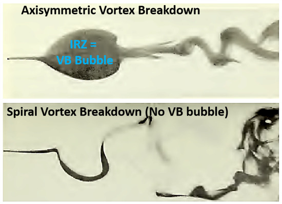
Figure 1.
Two different vortex breakdown modes. Figure taken from Sarpkaya [31]. (Top): axisymmetric mode with vortex bubble (inner recirculation zone). (Bottom): vortex breakdown spiral mode.
One of the most important features of swirling flows is the vortex breakdown because of its role in establishing a swirling flowfield, as can be seen in Lucca-Negro and O’Doherty [13], Benjamin [34], Harvey [35], Delery [36], Shtern et al. [37]. The vortex breakdown occurs, for swirl-stabilized systems, when the level of rotation reaches a critical value where an abrupt change characterized by a stagnation point with a subsequent representative reversal velocity region such as the inner recirculation zone in a combustor is formed, as can be seen in Hall [8]. The vortex breakdown can be triggered by an increase in cross-sectional area as it reduces the axial velocity and consequently increases the swirl number. This physical phenomenon has been experimentally investigated by several researchers and research groups to determine the regimes of vortex breakdown (shape and frequency). Among these studies, several shapes of the vortex breakdown have been visualized and observed as a function of the Reynolds and swirl numbers, as can be seen in Billant et al. [30], Sarpkaya [38], Faler and Leibovich [39]. The vortex breakdowns are of different shapes: axisymmetric giving rise to the inner recirculation zone (also known as a vortex breakdown bubble in the top of Figure 1), a spiral helix giving rise to a type of helical structure (rotating but not necessarily precessing) in the bottom of Figure 1, or a spiral double helix with sub-variants. The inner recirculation zone due to the vortex breakdown and the precessing vortex core coexist in several cases. The motion of precession is defined when the associated axis of rotation is circling around another fixed point than the combustor axis. For example, for the precessing vortex core, the central vortex core of the flow has a shifted rotating motion around the centre of the combustor. In other words, its center of rotation is not on the centerline. In many configurations, the swirl motion is taking place in a system with a central bluff-body that can inhibit the formation of the PVC because of the absence of any vortex core on the centerline.
The vortex breakdown regime can be affected by the combustor radius to length ratio (R/L), known as the confinement ratio in Gelfgat et al. [40]. Another ratio used is the ratio of injector cross-sectional area to combustor exit cross-sectional area. The swirl number can be modified by this ratio for a prescribed inlet velocity profile and subsequently impacts the vortex breakdown. Measurements of the axisymmetric vortex breakdown internal flowfield with LDV has shown that there is large periodic velocity fluctuations, as can be seen in Faler and Leibovich [41]. The vortex breakdown-induced flowfield have been investigated with particle-tracking velocimetry (PTV) measurements where fluid particles are tracked in a Lagrangian fashion, unlike PIV, where the Eulerian framework is used by Brücker and Althaus [42,43,44]. Subsequent flowfield analyses confirmed the existence of the bubble shape and spiral shape. The study of the spiral shape showed, with 2D velocity fields, that the stagnation point of the midplane was off the centerline and that this point precesses around the centerline. It is also important to study the transition between vortex breakdown regimes and their associated transitional mechanisms (also referred to as onset mechanisms) because it informs on ways to select or control a subsequent regime and thus enable the description and understanding of the underlying dynamic. The transition between the axisymmetric and spiral regimes, and the evolution of the bubble shape into the spiral shape, along with the formation of an inclined vortex ring as a function of the Reynolds number, has been documented experimentally by Brücker and Althaus [44]. A typical technique for studying such regime transitions is to impose prescribed perturbations on the base flow and to analyze its response. Flow visualization photographs have shown that the vortex breakdown and the rolling up of the shear layer around the jet into large-scale organized structures were amplified when forced by acoustic excitation, as can be seen in Panda and McLaughlin [45]. In this context, the visualization and measurements of velocity spectra along with ensemble averaged data enabled describing axisymmetric and helical instability waves. Their evolution along the axial direction informed on the propagation of these disturbances.
The vortex breakdown has been shown to induce the generation of a reverse flow called the inner recirculation zone (IRZ), also referred to as a vortex breakdown bubble (VBB). At a low swirl number, a reverse flow appears in the immediate downstream region of the bluff-body. At a moderate swirl number, the formation of an IRZ occurs in the downstream region of the flow, while at a higher swirl number, the two regions merge to form a unique IRZ. This merging has been observed with PIV measurements in Vanierschot and Van den Bulck [46]. The effect of the vane angle on the position and strength of the recirculation zone is shown in Figure 2. It is important to differentiate the PVC and the precessing of the IRZ as those can occur separately. Indeed, the precessing of the IRZ driven by the bluff-body (and not by the swirling flow) has been shown to be associated with low-frequency precession. Thus, in a swirling flow, these two effects could combined and include both the frequency of the PVC and the IRZ precession. There are limited studies that have focused on these effects. The precession motion of the IRZ associated with a bluff-body central rod configuration without a swirler has been observed by Vanierschot and Van den Bulck [47]. The effect of the flow rotation on this precessing motion has been investigated with a reduced order model to describe the influence of a swirl number on the wake dynamics by Vanierschot et al. [48]. In that latter configuration, the precession was not due to the PVC because a central rod directly inhibits the formation of the vortex core. In other words, the IRZ was driven by its own precessing motion. Experimental studies at distinct swirl numbers have also been undertaken to study the vortex breakdown regime, as can be seen in Santhosh et al. [49]. Flow visualization and the reconstruction of the pressure field from three-dimensional measured velocity data combined with the governing equations confirmed that the central vortex core, correlated with the low pressure region and high-pressure fluctuation levels on the central axis, generated the precessing vortex core around the vortex breakdown bubble, as can be seen in Percin et al. [50].
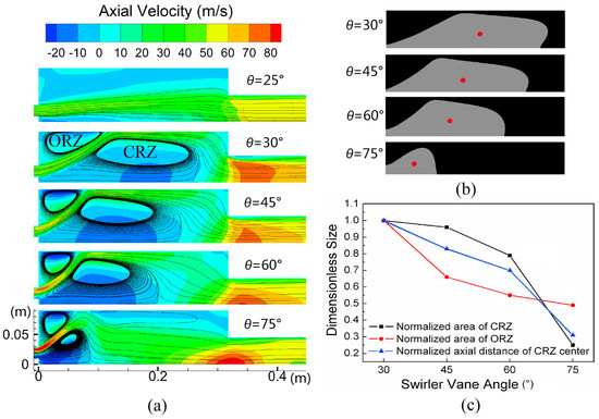
Figure 2.
Characterization of a swirling flow with a swirling inlet boundary conditions at various angles to study the effect on the inner recirculation zone. Figure taken from Xi et al. [51]. (a) Flowfields (cases 9 to 13). (b) Contours and center positions of recirculation zones. (c) Sizes of zones as a function of the vane angle.
As described earlier, significant knowledge can be gained on the mechanisms of swirling flames with the study of the non-reacting flowfield alone. Precise experimental characterization with state-of-the-art diagnostics has been important in identifying flowfield features and their details. A large number of research works have been published on this topic. This literature has been enabled to some extent by parametric studies and an advanced laser diagnostics experimental campaign. Parametric studies are important for design purposes and to capture the major effects of a single parameter on the dynamic of a system. Laser diagnostics can then be applied to a given or a set of selected values of a parameter to inform comprehensively on the flowfield. Such studies have been, for example, undertaken to experimentally and numerically quantify the effect of multiple parameters on the flow: Reynolds and swirl numbers in Ramos and Somer [52], Dellenback et al. [53], Wang et al. [54], outlet section ratio in Escudier and Keller [55], and injector size and location in Lilley [56]. While these studies are important, it is also critical to highlight the fact that the conclusions and findings can largely be controlled by the geometry (such as the presence of a center-body) at stake, and it is not straightforward to apply the findings to other cases. This further reinforces the need to conduct analytical works in this area.
In addition to the parametric studies and laser diagnostics measurements, the use and development of an image processing algorithm has enabled to detect and characterize swirling flow patterns. It has been particularly rich over the last decade with the use of algorithms such as proper orthogonal decomposition (POD) and dynamic mode decomposition (DMD). Unsteady swirling flows have been analyzed with PIV and POD or DMD in several works attempting to detect the main flow features such as the PVC or vortex shedding frequency and growth rates on the shear layers. Specialized functions have been also developed to detect vortex in swirling flows to identify the locations of the center and boundary of the vortex from the velocity field, as can be seen in Graftieaux et al. [57]. Such a characterization has been carried with POD on PIV measurements at multiple swirl numbers, as can be seen in Mak and Balabani [58]. The POD modes were found to be associated with the rollup occurring on the shear layers. The phase averaging and vortex identification techniques with criterion were used to study the helical vortices in swirling flowfield, as can be seen in Cala et al. [59]. Three-dimensional helical precessing coherent structures can be reconstructed with experimental and theoretical coupled analyses. To do so, the 3D oscillatory flow is postprocessed from 2D PIV data, combining POD, phase-averaging technique, and symmetry associated with specific helical structures, as shown in Oberleithner et al. [33]. It is important to point out that such POD or DMD tools allow important visualization, and thus, the description of the swirling flow global features is often complemented by phase-averaged or other diagnostics tools to reinforce the initial algorithm’s findings and interpretations.
A limited number of studies have focused, at fixed Reynolds numbers for a range of swirl numbers S, on the interaction and competition between different shear layer instabilities mechanisms identifying the most unstable mode (shape and frequency) in the flow as S varies. These studies focused on the convective/absolute behavior (i.e., downstream only or downstream/upstream propagation), local/global character (i.e., at one localized point in space or for a global mode), linear/nonlinear natures (i.e., a linear or nonlinear variation with respect to a variable) of the instabilities observed. The characterization and visualizations by Liang and Maxworthy [60] of the Kelvin–Helmholtz shear layers instabilities in the axial and azimuthal directions confirmed previously observed results by Billant et al. [30], Loiseleux and Chomaz [61]. The phenomenological description of three different flow regimes for an unforced swirling jet corresponding to three values of the swirl number has been conducted for regime identification by Loiseleux and Chomaz [61]. It was shown that the axisymmetric mode () associated with the formation of vortex rings was prominent for all regimes. In addition, the amplitudes of disturbances in the azimuthal and axial directions were calculated from the spatio-temporal diagram of the swirling jet evolution visualized with LIF. The first regime corresponded to , and axisymmetric deformations were gradually lowered as swirl increased. Between , axisymmetric and azimuthal deformations were found to rise towards constant levels. The amplitude of the azimuthal deformations for this second regime were larger than the axisymmetric ones. The third regime was characterized for where the amplitude of axisymmetric and azimuthal disturbances increased.
Discussion
It is of interest to summarize the findings of this section: (i) there are two main types of vortex breakdown, respectively, the axisymmetric regime—also known as the bubble regime—and a type of spiral or helical regime that is precessing or only rotating; (ii) the axisymmetric vortex breakdown induces a reverse flow, which is used in gas turbines combustors to anchor swirling flames, creating a favorable low speed region; and (iii) a PVC can be superimposed on the boundaries of the inner recirculation zone induced by the axisymmetric vortex breakdown and both the PVC and IRZ can exhibit precessing motions of the vortex core and of the stagnation point, respectively.
2.3. Theoretical Analyses for Non-Reacting Swirling Flows
Theoretical works on swirling flows have been initially focused on developing an understanding of the connection between the inner recirculation zone formation and the axisymmetric vortex breakdown occurrence as well as to build an understanding on the generation and propagation of coherent structures such as the spiral/helical vortices. Some elements relevant for combustion dynamics from published articles and reviews are briefly discussed here and other aspects are let out of the scope of this section. There are, as of today, several analytical approaches to tackle swirling flows. In the following section, elements of the state of the art for those methods are reviewed. Among the most contradictory issues among these theoretical analyses are the following: (i) the determination of the base flow for stability analysis; (ii) the difficulty to capture several of the fluid dynamics process theoretically simultaneously (see the description of the previous section); and (iii) the validation of these theories for various configurations.
Pioneering theories by Hall [8], Benjamin [34], Squire [62], Benjamin [63] assumed that the vortex breakdown features a propagating wave-like behavior and attempted to provide a critical tangential-to-axial-velocity ratio to predict the vortex breakdown formation to capture the vortex breakdown transition. This transition is manifested as the passage from jet flow to swirling flow with inner recirculation zone. In this approach, the supercritical character (convective instability: downstream propagation only) or subcritical character (absolute instability: upstream/downstream propagation) of the flow was studied. Other theoretical approaches consider the vortex breakdown a disturbance occurring when the vortex base flow azimuthal-to-axial velocity ratio reaches a critical value, as can be seen in Leibovich [9]. The axisymmetric vortex breakdown phenomenon criticality (i.e., the onset/transition when increasing the swirl number) has been studied with the axisymmetric Euler equations where regimes can be characterized, for example, for various levels of flow rotation, as can be seen in Wang and Rusak [64]. Few studies have focused on that aspect. For low swirl level, the jet has been shown to be unconditionally stable to any axisymmetric disturbance. Between low and high swirl level thresholds, the swirling jet evolves toward vortex breakdown if the amplitude of the initial disturbance is sufficiently large. At a higher flow rotation, any disturbances led to the vortex breakdown, as can be seen in Wang and Rusak [64]. The formation of the vortex breakdown, its intermittency, criticality/onset, and global instability character have been recently characterized as a function of the rate of swirl as well from PIV measurements by Oberleithner et al. [65].
Stability theories aim to define stability criteria for the vortex breakdown onset also referred as vortex breakdown criticality. Stability analyses split the flow into a base flow and a disturbance which is further decomposed into a growing and oscillating parts. The study of the growth or damping rates of these disturbances inform with regard to the stability of a particular disturbance. The selection of the base flow plays a crucial role in the determination of stability. It is directly due to the base flow speeds and indirectly due to the effect of these speeds into the wavevectors expressions. Stability analysis have, for example, been obtained for a Batchelor vortex base flow, as can be seen in Lessen et al. [66], Lessen and Paillet [67]. It was calculated that, if the swirl is increased, the disturbances are damped for small value of the parameter characterizing the degree of swirl. Furthermore, the helical modes evolution, defined as oscillating patterns that evolve along an helix, were determined as a function of that parameter for each mode. The linear stability analysis of swirling jet shear layer have been conducted employing potential flow theory to retrieve the growth rate and propagation velocity of both axisymmetric and helical waves, as can be seen in Martin and Meiburg [68]. Similar stability analysis have been carried out where the base flow is a Rankine vortex with a superimposed axial velocity profile, as can be seen in Loiseleux et al. [69]. The resulting dispersion relation was a function of two parameters: the swirl ratio and a parameter proportional to the axial flow velocity. It was shown that each azimuthal wave number m has a unique unstable Kelvin–Helmholtz mode and an infinite number of neutrally stable inertial modes. In addition, the results showed that the swirl intensity decreased the temporal growth rate of the axisymmetric Kelvin–Helmholtz mode (), which remains unstable for all axial wave numbers. For helical modes (), small amounts of swirl led to the resonances of the unstable Kelvin–Helmholtz mode and the inertial modes. The absolute or convective character of the instabilities has been determined for multiple swirling flows on canonical configurations with stability analyses. The effect of the base flow swirl velocity distribution was specifically investigated and was shown to lead to a different instability character, as can be seen in Loiseleux et al. [70]. The same effect of the azimuthal initial upstream velocity distribution base flow on the character of the instability and the stability of the azimuthal modes has also been carried out by Gallaire and Chomaz [71] where it was shown that the absolute instability of positive helical modes was fostered by centrifugal (radial) instability and azimuthal shear of the Kelvin–Helmholtz instabilities.
As pointed out earlier, the effect of flow rotation or swirl level is important on the dynamic of swirling flow as it impacts multiple aspects. The effect of how this flow rotation impacts the main flow instabilities and lead to the streamwise formation of coherent structures has been investigated recently, as can be seen in Oberleithner et al. [72]. Experimental and theoretical analyses led to the identification of centrifugal (radial) and shear layer instabilities whose growth rates were characterized as a function of the inlet swirl rate. Global stability and sensitivity analyses were conducted based on the POD of the snapshots taken from the DNS of a swirling flow. The stability analysis captured the precessing vortex core (PVC) and the sensitivity analysis revealed the near injector region as a key location to capture the global mode, as can be seen in Tammisola and Juniper [73]. These theoretical studies confirmed the experimental observations that the near injector region is indeed the region where the stagnation point precesses, where the vortex core is initiated and located. Other formulations relevant to swirling flow have been derived, for example, for cyclonic flow configurations by Vyas and Majdalani [74] with an inviscid solution describing the cyclonic motion of a bidirectional vortex in a cylindrical chamber.
Additional theoretical works include those on non-parallel flow assumptions, the bi-stability of swirling jets, and finite domain size effects. Parallel flow assumption concerns a flow that is assumed to vary in a single direction. Smith [75] describes the following: This approximation has been used extensively in theoretical studies of flow stability, in order that the partial differential equations describing an arbitrary small disturbance of a basic non-parallel motion may be reduced to a more readily analyzable ordinary differential equation, the Orr-Sommerfeld equation. For swirling flows, the situation is different and the base (and static flow) flow is highly 3D, so the assumption is limited. Bi-stability is considered in certain theoretical works where the recirculation zone is seen as either conical or bubble shaped, as can be seen in Moise [76]. Finally, the effects of finite domain size have been studied by Rusak et al. [77,78] in the case of subsonic swirling flows with a finite-length straight circular pipe addressing the effect of boundary conditions rather than considering the domain infinite.
Discussion
The theories described in this section have been comprehensively reviewed in Lucca-Negro and O’Doherty [13]. Additional reviews have attempted to unify the existing experimental, numerical and theoretical results, as can be seen in Hall [8], Leibovich [9], Escudier [10]. Combination of steady-state and stability analyses have been conducted by Wang and Rusak [64] to elucidate the transition from columnar jet swirling flow to axisymmetric vortex breakdown with axisymmetric unsteady Euler equations by describing the dynamics of such flow in a finite-length constant-area pipe without considering the role of the viscosity in this transition which is lacking. With existing and future numerical simulation computational codes (such as those based on the SD-FD) and resources, it will be possible to study and assess these theoretical studies and to further develop them. In addition, novel theoretical advances can be made using the static–dynamic flow decomposition (SD-FD), as can be seen in Palies et al. [28], Palies [79,80]. This decomposition consists of splitting each flow variable into a static and dynamic component. The static/dynamic decomposition for each variable (for example, density variable and velocity components) is first substituted into the governing equations (mass, momentum, and energy). In that framework, the static flow has no dynamical content. The obtained static flow has, by definition, zero frequency content, and therefore, the equations for the static flow are deduced by gathering terms that have no dynamical content (no fluctuation). Next, by subtracting this static equation from the original conservation equations, one obtains the dynamic flow equations. This equation can be used to study various unsteady phenomena at work.
As of today, most approaches are based either on splitting a flow variable with its time-averaged and an unsteady component (e.g., the turbulent fluctuation) in the time domain such as in RANS modeling or based on splitting a flow variable with its steady component (the base flow) and a small disturbance (the turbulent fluctuation) in the frequency domain for stability analyses. In several cases, however, the time-averaged component is different from the base flow and the fluctuations are not small anymore in the turbulent region of a flow having transitioned to turbulence. The proposed approach of decomposing into a static and dynamic components is a novel approach unifying existing frameworks and offering a route for novel insights in non-reacting and reacting flows physics, such as to uncover the flow features originating from the static or the dynamic components. One challenge is on the computational formulation of the SD-FD to solve the static and dynamic flow. The instantaneous flow, the static, and the dynamic flows provide different angles of flow physics and thus enable novel discoveries. This has been, for example demonstrated by Palies and Premchand [81].
2.4. Acoustics to Convective Mode Conversion Processes in Swirler
Chu and Kovásznay [82] introduced the notion that three modes of fluctuations or waves may be distinguished in a flow: acoustic, entropic, and vortical. These waves are characterized by their frequency, wave’s speed, and possible modal distributions for acoustics waves. It is important to define what is the mode conversion process in this context. In the field of study of waves, it is the change from one type of wave to another type. This process is not limited to the combustion dynamics field (as can be seen in Palies et al. [28], Noiray et al. [83], Komarek and Polifke [84], Palies et al. [85]) and has examples in other fields in which the literature is beyond the scope of the present article. It has relevant applications in turbomachinery for example.
Pioneering works and observations were conducted by Richards and Yip [86], Straub and Richards [87,88], and by Richards and Yip [86], which was the first study to report that When oscillation occurs, the pressure amplitude is sufficient to produce significant variation in axial velocity within the nozzle annulus. The fixed geometry swirl vanes will then produce a corresponding variation in tangential velocity. Thus, the annular nozzle flow is characterized by regions of high and low tangential velocity, convected along with the main axial flow. These variations in tangential velocity are proposed to alter the heat release rate as they arrive at the nozzle exit. Exactly how the fluctuations in tangential velocity would modify the heat release rate is unclear without a detailed picture of events occurring at the flame front. This process has been investigated and demonstrated to have a key role for swirling flames dynamics, as can be seen in Palies [89], Bunce [90], Albayrak [91]. While this phenomenon and its effects on flame dynamics have been recognized by many researchers in non-swirling by Noiray et al. [83] and swirling flows by Palies et al. [85], its visualization and direct experimental measurement are challenging and not sufficiently documented. This would require further measurement data and unsteady flow-flame analyses. Mode conversion refers to conversion from an upstream wave’s disturbance speed to a different downstream wave’s disturbance speed while keeping the oscillating frequency of those disturbances constant. In other words, the wavelength is modified. It has been shown that, when an acoustic wave impinges on a swirler, a convective vorticity mode is generated along with a transmitted acoustics wave, as can be seen in Palies et al. [28], Komarek and Polifke [84], Palies et al. [85]. This latter impacts the downstream flame dynamics. The acoustic-convective wave mode conversion process at swirlers induces a convective wave when the upstream acoustic wave are imposed. The determination and the modeling of these waves and their speeds is the topic of discussion, as can be seen in Palies et al. [28], Albayrak et al. [92]. The impact of mode conversion processes on flame dynamics is reviewed in this article in Section 5.
In the following paragraphs, expressions for the azimuthal and radial fluctuating amplitudes and their wavevectors are obtained for this process. These results provide the mode of propagation of azimuthal and radial perturbations due to mode conversion at the swirler. The starting point consists of writing the linearized Euler momentum equations in cylindrical coordinates along the radial and azimuthal directions with the axisymmetric assumption for the flow. These equations are the governing equations that can describe the non-reacting non-viscous flow downstream of a swirler in a linear regime. The fluctuating quantities are assumed to depend only on the longitudinal direction z. These equations are taken from Palies et al. [28]:
where is the fluid density and are the velocity components.
The fluctuating density has an upstream and downstream propagating component. The associated wavectors components are and and the amplitudes are and :
To reflect the downstream propagation of the fluctuating velocities and along the axial direction, the following Fourier decompositions are used (where the associated wavevector components are and and the associated amplitudes are and ):
Inserting Equations (5)–(7) into Equations (3) and (4) leads to two equations which are the functions of the fluctuating quantities and and their respective wavevector components and . Coupling the two equations obtained leads to:
The next step consists of expressing the real and imaginary parts of this last Equation (8) and expressed them for , which corresponds to the swirler outlet. It leads for the real part to:
And for the imaginary part, it leads to:
As a consequence, the ratio of radial and azimuthal convective wave amplitudes is obtained:
Making use of and noting the convective velocity of the radial fluctuations, the azimuthal component of the wavevector is:
It also possible to show that these results obey to both the mass and the axial momentum conservation equations under the assumptions of low Mach number, constant density, and constant homogeneous velocity field. It has been measured that the azimuthal fluctuations propagate at the convective axial velocity of the flow, implying that the term in brackets of Equation (12) is unity. It implies that . This demonstrates that the radial fluctuations also propagate at the axial velocity of the flow. In addition, it has been shown that the phase between the axial and azimuthal components is zero. As a consequence, as the waves propagate at the same speed, it is appropriate to indicate that the radial and azimuthal fluctuations have the same phase as their initial phasing at the swirler’s vane trailing edge is zero.
Discussion
In this section, it has been shown that the mode conversion process converts an acoustics wave, impinging the swirler into a convective wave and leading to an impact on the subsequent flame dynamics. Mode conversion, as defined here, is a process that was hypothesized early by Richards and Yip [86] but its initial modeling, description and effect in swirled non-reacting and reacting flows was described in Palies et al. [28], Komarek and Polifke [84], Palies et al. [85], Albayrak et al. [92].
Additional work needs to be undertaken with respect to this phenomena in term of experimental characterization and measurement, theoretical, or computational modeling. Future investigations should be undertaken in the following areas: (i) determination and quantification of the role of mode conversion process for broad-band noise in addition to existing works on harmonic waves. How this signal will behave with respect to mode conversion will be of interest to determine a frequency and amplitude threshold leading to mode conversion; (ii) comparison of the numerical simulation results of a given configuration obtained with a fully compressible code versus a low Mach number code to assess the effect of mode conversion at the swirler and the resulting turbulence induced by the swirler on the local flame wrinkling. Indeed, beyond swirling flame dynamics, such mode conversion could be of importance in refining the understanding of turbulent combustion in swirling flows; (iii) the continuation/extension of the theoretical investigation presented in the above paragraphs, and the characterization of wavevector and wave speeds to other regimes by including the viscosity effects which are currently not taken into account in the theoretical derivation; (iv) the continuation of work on decomposing flows into static and dynamic components; and (v) conduct numerical simulations and experimental measurements in order to characterize wave speeds, frequencies, and directions of propagation, with dedicated post-processing tools; (vi) extension of existing theory taking into account the coupling with the G-Equation by Markstein [93] in order to obtain a complete mode conversion/combustion dynamics description; and (vi) the study of mode conversion in the SD-FD framework.
2.5. Numerical Simulations Methodologies
This section discusses which flow features are captured by numerical simulations including Reynolds-averaged Navier–Stokes (RANS), large-eddy simulations (LESs), and direct numerical simulations (DNSs) because each of these methods are appropriate to capture particular features. Computational fluid dynamics numerical simulations have generally reached a very advanced level of accuracy and are recognized as one of the most advanced, current and future tools for fluid dynamics research and for design purpose. Nonetheless, as DNS modeling method cannot use its full potential in general because of high CPU resources needs, the use of less demanding RANS, and LES methods are and will be required in the future. The underlying models will have to be improved, and the modeling strategy refined by including the assumptions used.
Numerical simulations to describe the occurrence of the vortex breakdown in swirling flows have been performed with various methods: analytical-based simulations, RANS, LES, and DNS methodologies. The first class of simulations is critical to capture the major roles of the mechanisms at work. This class of models has been, for example, implemented to study the role of the vortex dynamic in establishing the vortex breakdown, as can be seen in Darmofal [94]. Results showed that the initial vortex core and associated axial vorticity was tilted in the azimuthal direction by the effect of inlet swirl motion. Such analytical-based simulations have also been used to document the growth and nonlinear evolution of the helical perturbations of swirling flows. It demonstrated the effect of swirl on the helical perturbation growth and the mechanisms of vorticity concentration, reorientation, and stretching, as can be seen in Martin and Meiburg [95].
The RANS simulation of swirling flows have been widely documented. Two aspects are particularly important: the inlet flow profile and the turbulence closure model. The inlet flow profile is key for the prediction of the swirling flowfield. The simulations of confined swirling flows with swirler outlet velocity profiles or prescribed canonical profiles have highlighted the important sensitivity of the CFD domain inlet boundary mean radial velocity profile on the swirling flowfield, as can be seen in Grinstein et al. [96]. There is evidence that the swirler is an intense source of turbulence in Kilik [97], Raj and Ganesan [98], He et al. [99].
Numerous numerical studies have focused on the effect of the turbulence closure model on the mean and turbulent swirling flow quantities, as can be seen in Sloan et al. [11], Nikjooy and Mongia [100]. Methods for axisymmetric, incompressible, turbulent swirling flow modeling that compare the effects of the inner and outer swirl, axial velocity ratio distributions, and Reynolds numbers on the formation, size, and location of the inner recirculation zone have been proposed, as can be seen in Kubo and Gouldin [101]. With this method, the turbulence closure model is based on the resolution of transport equations for the turbulent kinetic energy rate and dissipation. The Reynolds stress transport model is the most accurate to capture swirling flows, as can be seen in Sharif and Wong [102], Jakirlic et al. [103]. The comparison and evaluation of turbulence closure model have been conducted on four swirling flow configurations and it was shown that the Reynolds stress transport model prediction was closer to the experimental measurements for the mean velocity components than the two other models assessed (k- model and algebraic stress model). The difference between models was very significant in some regions of the flow (+/− 10 m s−1). The Reynolds stresses were over-predicted, however. The k- model has been shown to not be adapted, as can be seen in Favaloro et al. [104].
RANS simulations were used as an initial step towards the design of a swirl-stabilized combustor by Palies with the Reynolds stress model and a solid body rotation inlet flow profile. Two-dimensional RANS axisymmetric numerical simulations were carried out to evaluate the formation of the recirculation zone for a given inlet flowfield prior to the design of the swirler. An example of the results for a given confinement ratio are reported in Figure 3. The three components of the velocity, respectively, axial, swirl, and radial components are plotted from top to bottom. The inlet swirl velocity field induces the formation of the inner recirculation zone. One also observes the solid body rotation of the flow in this example and the radial velocity maximum values region on the swirling jet.
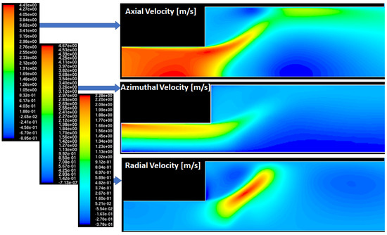
Figure 3.
RANS modeling with the Reynolds stress model of a swirling flow for configuration design (unpublished results from Palies doctoral thesis. From ((top) to (bottom)): axial, azimuthal, and radial velocities. Axial velocity ranges from −0.88 to 4.4 m s−1. Azimuthal velocity ranges from 0 to 4.67 m s−1. Radial velocity ranges from −0.38 to 2.28 m s−1. A solid body rotation of the flow is prescribed at the inlet.
The LES of swirling flow is a major tool for numerical predictions and usually a step prior to conduct reacting flow studies, as can be seen in Gicquel et al. [19]. It has been shown and it is now established (for laboratory-scale systems) that the upstream’s swirler inlet turbulence level has little impact (in contrast to the mean/static flow) on the flowfield turbulence as the major sources of turbulence are the swirler and the resulting swirling flow velocity gradients, as can be seen in Sloan et al. [11], Leschziner and Hogg [105], Dong and Lilley [106], Xia et al. [107], and Ahmed [108], Palies and Acharya [109]. It is important for the modeling of these flows. Future works should assess the effect of a more realistic turbulence intensity and Kolmogorov scale, such as existing engine high-pressure compressor stages, with respect to the swirling flow turbulence inside the combustor. Other important aspects for these flows include the vorticity dynamics and the acoustic effects occurring within the swirling flow and its shear layers and the interaction of acoustics waves with the swirlers. The use of simulations and methods including POD, spectral analysis, and flow visualization has shown to be critical for the study of swirling flow to investigate the 3D non-reacting turbulent flowfield produced by swirlers or tangential injection. Particular attention has been on the effect of the swirl number and the swirlers. It has been shown that increasing the swirl number reduces the flow oscillation of the azimuthal component occurring between the first and second radial swirler shear layers, which caused a reduced longitudinal oscillation, as can be seen in Lu et al. [110], Wang et al. [111], Wang and Yang [112]. The LES of gas-turbine industrial swirl injector flow dynamics has been undertaken to study the central and corner recirculation zones flowfield, the precessing vortex core and the shear layers for both co- and counter swirling swirlers. In configuration with two radial swirlers, it has been demonstrated that the swirling direction (determined by the swirler’s vanes directions) of the second swirler influences the flowfield in term of recirculation zone extend and turbulence level. For example, when this second swirler is counter-swirling (rather than co-swirling) with the first one, it reduces the recirculation zone length and increases the turbulence level, as can be seen in Wang et al. [113]. LES and experimental measurements have also been carried out to investigate the swirling flowfield generated on the burner studied by Duwig et al. [114]. The measurements showed that different outlet geometries had effects on the strength and position of the coherent structures of the flow. The PVC was captured based on the application of the POD algorithm to the LES data, as can be seen in Duwig et al. [114]. The effect of swirl number on the coherent structures of a swirling flow has been studied with LES (Stone and Menon [115]) and detached-eddy simulations (DESs), as can be seen in Javadi and Nilsson [116]. The investigation of the effect of the Reynolds number and the swirl number on the formation of the swirling flowfield have been undertaken to form a regime diagram identifying the different coherent structures of the flowfield. The regimes reported on this diagram were the consequences of a set of mechanisms including the centrifugal (radial) instability, the Kelvin–Helmholtz instabilities, restoring effect of the center flowfield, and the wall boundary layer damping effects, as can be seen in Wang et al. [117].
While the previous paragraphs have reviewed the state of the art for RANS and LES modeling approaches of swirling flows, it is also important to provide the current state of the art on the DNS of non-reacting swirling flows that is notably less documented. Canonical swirling flow numerically investigated with a focus on the vortex breakdown regimes for multiple low Reynolds numbers, multiple swirl levels and multiple ratio of the axial jet velocity to the axial free stream velocity have been documented in the literature. Visualizations of the criterion and the streaklines from the inlet of the domain provided unique information on the flow [118]. Such a study confirmed the elements of theory by Benjamin [34] for swirling flow criticality/onset. Other efforts have been, for example, undertaken in Freitag and Klein [119] to investigate the precessing vortex core, its location, and influence on the isothermal flowfield.
Remark
RANS or URANS (unsteady RANS) numerical methodologies offer considerable advantages in terms of CPU cost compared to the LES method. While capturing specific essential aerodynamic structures, such as the inner recirculation zone (RANS), the vortex shedding inducing flame rollup, or the precessing vortex core (URANS), these methods do not allow one to capture of the acoustics or the turbulent fluctuation dynamics because of the time averaging. There are limited studies investigating the sensitivity of RANS or URANS models to flow feature occurrences. This is lacking as of today. In general, the assessment is conducted by comparing the flow variables from simulations and experiments rather than the 3D features size and strength. Nevertheless, a few studies have demonstrated that such features can be captured by RANS or URANS (but without a sensitivity analysis to the models), in terms of frequency and size, for example, as can be seen in Syred [15] or Shamami and Birouk [120]. Contrarily, LES allows the capturing of acoustic and turbulent phenomena. DNS, by resolving all scales, allows one to resolve all unsteady fluctuations, a major advantage. The numerical formulations are, respectively, time-averaged (RANS) and spatial-averaged (LES) forms of the governing equations. It is recommended that the swirler is to be included into LES numerical simulations to capture both the instantaneous flow and its fluctuations, and the dynamic of the mode conversion process.
2.6. Swirling Flows Versus Swirling Flames
Prior to discussing the physical and chemical insights of swirling flames, it is important to review a few articles that focus on both the non-reacting and reacting flowfields, as specific aspects of these flowfields are different, such as the onset of vortex breakdown, the strength of the inner recirculation zone, the occurrence of the PVC, or the amplitudes, frequencies, and growth rates of shear layers instabilities.
Several studies have centered on characterizing these differences. Initially, laser diagnostics experiments were performed on swirling flowfield with LDV, for example, for co- and counter swirlers configurations. In these studies, the subsequent effects on the formation of the inner recirculation zone were investigated by Gouldin et al. [121]. Following these initial studies, localized measurements of the frequency content of a swirling flow with and without combustion have been conducted in Gouldin et al. [122]. A periodic low frequency motion was observed near the swirling jet centerline and it was associated with the axial oscillating motion of the recirculation zone. This phenomenon was observed to be amplified with combustion. Additionally, higher frequency oscillations were recorded in the vortex core region and were linked to helical waves. Non-reacting and reacting flows velocity field and Reynolds stresses have been experimentally investigated with LDV. The major differences between the two cases were that, in the reacting case, the recirculation zone was shortened and widened, and the peak reversal velocity was heightened, as can be seen in Brum and Samuelsen [123]. It is known that the precessing vortex core may or may not exist in non-reacting and reacting flowfields. On a given setup, it has been shown that the non-reacting fluctuating flowfield included a weakly excited acoustics mode and the PVC oscillation, with the latter inducing the largest pressure fluctuation in the combustion chamber, as can be seen in Roux et al. [124]. With reacting flow conditions, it was found on the same setup that the PVC was damped, and that the dominant unsteady motion was driven by the acoustics mode combustion instability. In other words, the passage from non-reacting to reacting conditions shifted the unsteady source and the frequency content. The analysis of isothermal and reacting flow conditions in another setup led to the same conclusion regarding the PVC which was suppressed in the reacting configuration, as can be seen in Schneider et al. [125].
Stability analyses of reacting swirling flows are limited in the literature and a complete theoretical framework has yet to be derived and applied. This approach will aim to determine the stability of the reacting flows, i.e., the mode shape and mode frequencies of the most dominant structures/patterns, firstly under non-reacting conditions to identify flow structures. Then, as a next step, the approach can take into account the combustion processes and the coupling with acoustics, leading to thermoacoustic instability. Indeed, as of today, these stability analyses are tackled separately, as can be seen in Section 4 on combustion instability stability analysis, making use of the flame response for thermoacoustically coupled cases. The effect of the base flow in the stability analysis of reacting flows is a topic of discussion in the literature for non-reacting and reacting flows, as can be seen in Beneddine et al. [126], Karban et al. [127]. The effects of high-speed compressibility (as can be seen in Rusak et al. [78]) or combustion (as can be seen in Rusak et al. [128]) on the onset of vortex breakdown have been analyzed in detail with stability analysis based on the governing equations assuming no viscosity and thus not taking into account the important viscous effects in the case of low speed swirling flows. The attempt of linear stability analysis with a localized approach in order to predict the growth of reacting axial shear layers perturbations towards a coherent vortex was recently applied in Oberleithner et al. [129]. These recent stability analyses investigate the formation of shear flow disturbances but they do not take into account acoustics, and subsequently the mode conversion processes impacts the flame response, which dominates the dynamics in many configurations. Experimental and theoretical works have to be jointly conducted to investigate the underlying mechanisms between non-reacting and reacting swirling flows. Such an approach was recently applied to the onset of the vortex breakdown and demonstrated the role of inlet preheating on the downstream displacement of the IRZ with respect to non-preheated non-reacting case, along with the role of the chemical reactions on displacing upstream the location of the IRZ. Whereas as the equivalence ratio increases, this position is again further moved downstream and the flame location modified with respect to the IRZ, as can be seen in Umeh et al. [130].
Discussion
Now, a cross-comparison of key conclusions and methods of study of swirling flows versus swirling flames is conducted. The first question discussed is that of which features of non-reacting flows and their hydrodynamic stability play a role for the flame dynamics and thermo-acoustics stability of swirling flames ? Answering this question includes listing all non-pulsated flows features that can be observed without any external forcing. These include vortex breakdown by Lucca-Negro and O’Doherty [13], the formation of the inner recirculation zone by Beer and Chigier [4], helical instability by Oberleithner et al. [33], and precessing vortex core by Syred [15]. These flow features may or may not subsist in the presence of chemical reactions under reactive conditions. Their frequency, size, shape and strength may also change. They will induce an unsteady heat release rate in reacting cases that will or will not couple with the combustor acoustics. Additional mechanisms are at work when upstream forcing is applied including the mode conversion process at the swirler and vortex-shedding. As the amplitude of forcing increases, these two mechanisms become dominant in organizing the flowfield. Both of these are also at work in reactive conditions as outlined in the next sections of the manuscript. These two mechanisms drive the response of swirling flames.
2.7. Conclusions
In order to conclude Section 2, it is important to remember the complexity of a swirling flow which features many different characteristic structures. These include the shear layers (axial inner, axial outer, and azimuthal) due to velocity differences, the helical instability rotating or precessing (such as the precessing vortex core), and the vortex breakdown and its associated inner recirculation zone. These structures depend on geometry, swirl, and Reynolds numbers. In addition, the dynamics of the upstream flowfield is important to take into account, as it will be shown in subsequent sections. This includes the mode conversion processes occurring at the swirler or at the experimental setup backplane. Future research should include detailed coupled simultaneous visualizations of the flow features and their characterization, with given quantified parameters/metrics for their identification. This will allow one to further describe their individual and coupled effects on the unsteady heat release. In terms of non-reacting swirling flow experiments, the role of the swirler and central bluff-body in inducing the finest and largest turbulence scales should be a major research route. In addition, the swirler’s capability to mix various species for the future development of partially and fully premixed injection systems should be investigated. Both of these aspects should include the effect of geometry, angle, thicknesses, and rotation levels with detailed experiments enabling optical access for direct visualization and analysis. In term of numerical modeling, these experiments could be the validation basis of turbulence and mixing LES models and advanced DNS for non-reacting conditions at various operating pressures and temperatures. Theoretical models presented in previous sections provide a path towards the theoretical development of reduced order models for studies on mode conversion, turbulence generation within the swirler and mixing between species. The effect of operating pressure and inlet temperature should be considered and its influence on the turbulence scales (spatial and temporal scales, amplitudes, intensity) investigated.
3. Swirl-Stabilized Partially and Fully Premixed Flames
3.1. Introduction
The next sections are dedicated to swirling reacting flows. First, the specifics of these flows in the presence of chemical reactions are highlighted. Secondly, selected laboratory-scale experiments are presented. Thirdly, the elements of turbulent combustion and flame stabilization are reviewed and discussed, along with the perspectives for future efforts. As for non-reacting swirling flows, reacting swirling flows have been widely documented and detailed measurements and modeling under statistically steady combustion regime have enabled significant progress in their physical description. This is the focus of this section.
3.2. Swirling Flames Complexities Due to Chemical Reactions
The addition of chemical reactions to swirling flows induces complexities in the flowfield, and consequently, in their characterization, analysis, and understanding. Nevertheless, several of those issues have been addressed, and to date, experiment diagnostics and capabilities enable the visualization and measurements in such flows with great details. Current experimental techniques have been shown to capture large flow scales and flame contour fields. The flowfield, including the inner recirculation zone limits, was identified in Taamallah et al. [131]; the temperature and the mass fraction fields were measured by Meier et al. [132]; the precessing vortex core was characterized in Syred [15]; the helical vortex core and shed vortices were studied by Steinberg et al. [133]; and the outer shear layers were visualized in O’Connor [134]. Future progress will be enabled by the higher temporal and spatial resolutions of the diagnostics utilized to allow the capture of the flame’s inner structure for such a flow, which remains a major challenge.
The key changes that chemical reactions add to isothermal confined swirling jets are given as follows: (1) the increase in the strength and size of the recirculation zone under reacting conditions, (2) the suppression or triggering of the PVC, (3) the increase in swirling jet/flow angle, and (4) the high-temperature regions impacting the local fluid physics (such as turbulence scales, vorticity, shear-layers) via the change in kinematic viscosity and the acoustics via the modified sound speed.
Swirling flows consist of global flow features (ORZ, IRZ, PVC, HVC, etc.), also referred to as large-scale flow features that are intrinsically driven by the geometry setup and the operating condition. These flow features can be identified and analyzed with several experimental diagnostics combined with post-processing techniques such as POD or DMD. They are also directly responsible for the local reacting flow physics as a given large-scale flow structure participates in defining variables such as the local velocity, temperature, and species gradients. Accordingly, in terms of future work, studies focusing on the impact of these local effects from large-scale flow features should be undertaken from a modeling, experimental, and theoretical perspectives. For example, for the PVC and the helical vortex core, advances have been made in several studies under non-reacting, reacting, and thermo-acoustically coupled conditions (as can be seen in Steinberg et al. [133,135], Moeck et al. [136], Oberleithner et al. [137], An et al. [138], Taamallah et al. [139], and Zhang et al. [140]) in order to identify regimes of occurrence for these flow features, their frequency, and their role in thermo-acoustic instability coupling.
There is no general criterion or conditions to date to predict the occurrence of these flow features. Research has focused on linking the large-scale flow features to the local flowfield for swirl flame stabilization studies, as can be seen in Chterev et al. [141], computational models improvements (Roy et al. [142], Douglas et al. [143], Kazbekov et al. [144], Kazbekov and Steinberg [145]), and NOx emissions assessment, as can be seen in Luckoff et al. [146].
The effect of hydrogen addition for partially premixed and fully premixed swirled flames has been the topic of a few studies which will be included in the next subsections. This is illustrated in Figure 4 for an hydrogen enriched partially-premixed flame. This section now reviews laboratory-scale setups where flow features have been observed. While the existing descriptions of reacting swirling flows are important and allow physical understanding, future diagnostics and experimental work should focus on the detailed analysis of the flame front of premixed flames with the measurements of flame thickness, inner temperature (the temperature where the peak of heat release rate occur), species reaction rates, and flow speeds. There is significant knowledge on 3D flow features, but considerably less on the local inner flame structure of swirling flames.
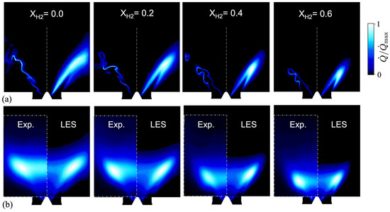
Figure 4.
Effect of hydrogen addition to a partially premixed methane–air flame. Figure taken from Garcia et al. [147]. (a) Instantaneous (left half) and time-averaged (right half) heat release rate. (b) Time-averaged of experimental OH∗ line of sight (LOS) on the left half and LOS of time-averaged heat release rate on the right half.
3.3. Laboratory-Scale Experiments
Swirl-stabilized combustion dynamics has been or is currently the topic of many investigations and studies worldwide. In this section, a comprehensive list of these systems outlining their key geometrical and operating conditions is gathered in Table 2. Furthermore, selected laboratory-scale swirl-stabilized combustors and the major findings are discussed. These configurations will be referenced and further discussed throughout this article.
The Preccinsta combustor of Meier et al. [132], Lartigue et al. [148] has been a pioneer in supporting and advancing combustion studies for both combustion dynamics and turbulent combustion of swirled flames. Advanced laser diagnostics were deployed to gain validation data for the subsequent detailed LES simulations conducted on this setup. It also enabled the analysis and understanding of large-scale flow features such as the helical mode forward. These studies are significantly discussed in the next section. The combustor operates with CH4 and air premixture at a pressure of 1 atm and an inlet temperature of 300 K. The optical access around the flame was made of square quartz windows. The combustor was utilized at two main combustor operating points: a stable and an unstable point corresponding, respectively, to equivalence ratios of 0.83 and 0.7. The three-component velocity field was measured with LDV, the flame structures were measured with chemiluminescence and OH planar laser-induced fluorescence (PLIF) imaging. The joint probability density functions of main species’ concentrations, mixture fraction, and temperature were measured by laser Raman scattering. Phase-locked measurements were performed for the unstable point at an equivalence ratio of 0.7. High-speed PLIF and PIV diagnostics were applied on the Preccinsta combustor operating at spray conditions by Salaün et al. [149]. POD was used to extract the unsteady flame features. The laboratory-scale gas turbine model combustor by Weigand et al. [150] was used to study three CH4–air partially premixed flames. These flames were investigated using the LDV, the PLIF of OH and CH radicals, and laser Raman scattering. Three flames under different operating conditions were compared along with their flowfields and flame structures. Mean values and fluctuations of the species concentrations, mixture fraction, and temperature were measured. Those combustors have been extensively investigated and characterized numerically and experimentally. Similar simultaneous detailed measurements campaigns have been conducted on other burners to investigate fuel spray distribution within the flowfield and flame stabilization, as can be seen in Chterev et al. [151].
The LSI configuration is an ultra-low emissions technology for gas turbines and industrial heaters developed by Cheng et al. [152,153]. It has been a major experimental setup pioneering turbulent combustion characterization and moving swirled flame stabilization research forward for such flames. This setup has been replicated in other studies worldwide and modeled with various computational codes and approaches as discussed in the next section. The LSI setup uses an aerodynamic flame stabilization method developed for fundamental research on turbulent premixed combustion Chan et al. [154], Cheng [155]. The specific flowfield and self-similarity features as well as the flame characteristics have been investigated by laser diagnostics. The LSI does not present an inner recirculation zone. The LSI flames were a CH4–air flame of equivalence ratio and a 0.9H2-0.1CH4-air blend flames (volume-based, as can be seen in Therkelsen et al. [156] at and for an injector bulk flow velocity of 18 m s−1. The laboratory-scale combustor by Taamallah et al. [157] has been used for combustion dynamics studies. The dynamic stability map of the combustor was investigated with specific attention on the changes of the flame shape as the equivalence ratio is increased. The authors modified the combustor length to decouple the acoustics from the flame response, over an equivalence ratio range of interest. A comparison of two different combustor flame tube lengths was performed and the flame shape transition was studied along with the effect of hydrogen addition on the dynamic stability. The combustors by Bellows et al. [158] and by Thumuluru and Lieuwen [159] were used to experimentally investigate the response of lean premixed swirling flames to imposed flow modulations, documenting one of the first experimental swirl flame transfer functions in the linear regime. The mechanisms of flame responses were investigated using phase-locked, and two-dimensional OH-PLIF imaging on both combustors. The single sector combustor of O’Connor and Lieuwen [160] was designed to support acoustic modes in the combustion chamber that are transverses with respect to the axis of the combustor. The transverse acoustic field is generated by two sets of loudspeakers on each side of the combustor. This setup replicates some features of acoustics azimuthal modes of an annular chamber like the direction of propagation of the wave and its fluctuation direction. These studies were pioneering some of the effect of azimuthal acoustic mode on flame dynamics prior the development of the optically accessible annular chamber. The annular combustion chamber of Bourgouin et al. [161], Vignat [162] is an example. The system comprises a plenum, a set of 16 swirling injectors, and an annular combustor formed by two concentric transparent quartz cylinders for optical access. This type of configuration with annularly distributed multi-injectors has brought a new angle to the studies of swirl-stabilized systems by considering additional phenomena in complement to longitudinal combustion dynamics and transverse mode studies. Indeed, phenomena like ignition with annular flame propagation from injector to injector, traveling/spinning or standing annular acoustics modes investigations were initiated. The configuration by Stopper et al. [163] was studied with multiple experimental diagnostics including PIV to characterize the flowfield, 1D laser Raman scattering to determine the joint probability density functions of species concentrations, mixture fraction and temperature, OH-PLIF to visualize the flame front, chemiluminescence measurements of OH∗ to determine the lift-off height and size of the flame, and fluctuating pressure acquisition. The OH-PLIF images showed that the flame was located between the inlet fresh gas stream and the recirculated combustion products. The flame front structures varied significantly with the Reynolds number from wrinkled flame fronts to fragmented and strongly corrugated flame fronts. The same configuration was investigated in Bulat et al. [164] as well with a joint experimental and numerical effort. It was shown that the LES predictions were in good agreement with the experimental data for the flowfield, temperature, and major species. Different reaction mechanisms did not affect the flowfield as much as the temperature and species profiles, which showed the clear impact of the selected reaction mechanism.
Table 2.
Combustion dynamics configurations table. The table lists the first author, the reference article, the combustion mode, the fuel, the swirler geometry, the diagnostics implemented, the inlet static pressure, the inlet static temperature, the equivalence ratio, the power, the swirl, and the Reynolds numbers.
| Configurations | Mode | Fuel | Swirler | Diagnostic | P [atm] | T [K] | Power [kW] | S | Re | ||
|---|---|---|---|---|---|---|---|---|---|---|---|
| Single injector | |||||||||||
| Komarek | [84] | pre. | NG | ax. swirler | FTF | 1 | 300 | 0.77 | 70 | ||
| Dawson | [165] | ||||||||||
| Richecoeur | [166] | p-pre. | C3H8 | tang. entries | FI + Ac | 1 | 300 | 0.75–0.80 | 33–35 | 0.7 | |
| Weigand | [150] | p-pre. | CH4 | 8/12 blades rad. dual-swirler | Phase-locked | 1 | 300 | 0.55, 0.75 0.65 | 7.6–10.3–34.9 | 0.55 0.9 | 15,000 58,000 |
| Hermeth | [167] | p-pre. | CH4 | ax./diag. 8/24 vanes | 17 | 700 | 100,000 | ||||
| Cochet | [168] | pre./liq. | CH4-Jet A | Preccinsta swirler | Time-averaged + HS | 1–5 | 300–600 | 0.6–1.8 | |||
| Biagioli | [169] | p-pre. | 2 half cones | Time-averaged + PL | 1 | ||||||
| Chterev | [170] | pre. | NG | FI + PIV + Co | 1 | 366–563 | 0.58–0.8 | 0.6 0.80 | 10,000 | ||
| Bellows | [171] | pre. | NG | 40° ax. blades | HS + PL | 1.7 | 300 | 0.83–1 | <100 kW | 1 | 22,500 |
| Schuermans | [172] | p-pre./liq. | 2 half cones | FTF | full | ||||||
| Dhanuka | [173] | p-pre. | Jet-A | twin annular prem. swirler | PLIF + PIV | 4.5 | 505 | 0.16-0.44 | |||
| Williams | [174] | pre. | CH4 | 6 45° vanes ax. swirler | 1 | 300 | 0.56–0.9 | 0.87 | 13,800–48,300 | ||
| Bellows | [158] | pre. | NG | 40° ax. vanes | HS + PL | 1 | 300 | 0.8 | <100 kW | 1 | 21,000–43,000 |
| DiSabatino | [175] | pre. | CH4 and C3H8 | - | FTF + PL | 1–5 | |||||
| Taamallah | [157] | pre. | CH4-H2 | 8 ax. blades | HS + Time-averaged | 1 | 300 | 0.5–0.75 | kW | 0.7 | 20,000 |
| Schimek | [176] | p-pre. | NG | 16 passages movable block | PL | 1 | 300–773 | 0.65 | 0–2 | 37,000 | |
| Terhaar | [177] | pre. | NG | movable block | HS PIV, OH | 1 | 300 | 0.7 | 0.6, 0.8, 1 | 35,000 | |
| Kim | [178] | pre | NG | 8 ax. vanes | PL, FTF | 1–4 | 373–573 | 0.55–0.75 | 0.7 | 10,000 | |
| Seo | [179] | pre. | NG | ax. 45° vane | AC + FI | 4.6 | 570–660 | 0.5–0.7 | 96 | 0.76 | 35,000 |
| Kim | [180] | pre. | NG | FI + PIV | |||||||
| Huang | [181] | liq. | Jet-A | ax. swirler 6 60° vane | 10 | 650–800 | 0.37–0.7 | ||||
| Apeloig | [182] | liq. | keros. | ax. + rad. | PL | 1–50 | 300–900 | 0.4–1.05 | |||
| Tachibana | [183] | p-pre. | ax. swirler | PL + Ac | 700 | 0.5 | |||||
| Tachibana | [184] | ||||||||||
| Providakis | [185] | p-pre. | Jet-A | pilot/main co-swirlers | PDA + PIV + PLIF + HS | 1 | 473 | 0.6 | 85 | 1 | |
| Anacleto | [186] | pre./liq. | C3H8/ | adjust. blade angle swirler | 1 | 573 | 0.5 | 0.5–1.05 | 80,000 | ||
| Rofi | [187] | pre. | CH4 | ax. swirler Ansaldo Energia | 1 | 600 | 0.51 | 2000 | |||
| Cheng | [152] | pre. | CH4-H2 | ax. blades + center holes | Phase-locked | 1 | 300 | 0.58–0.95 | 15–560 | <0.12 | |
| Lückoff | [188] | pre. | NG | ax. swirler | FTF + PL | 1 | 293 | 0.65 | 67 | 0.7 | 30,000 |
| Kim | [189] | pre. | CH4 | 2 ax. swirlers 6 45° vanes | FTF + PL | 1 | 300 | 0.6 | 10 | 0.55 | 8000 |
| Palies | [190] | pre. | CH4 | 8 twisted ax. vanes | PL | 1 | 300 | 0.7 | 2.5 4 | 0.55 | 3900 6000 |
| Palies | [191] | pre. | CH4 | 18 rad. vanes | Phase-locked | 1 | 300 | 0.7 | 2.5 | 0.55 0.65 | 3900 |
| Lartigue | [148] | pre. | CH4 | 12 rad. passages Turbomeca | Phase-locked | 1 | 300 | 0.7 0.83 | 25 30 | 0.6 | 35,000 |
| Stopper | [163] | pre. | NG | 12 passages rad. swirler | 3 6 | 673 | 0.6 | 335–1000 | 0.46/1.02 | 39,000–120,000 | |
| Kraus | [192] | p-pre. | NG | in./out. rad. swirlers | PL | 1 | 300 | 0.6 0.85 | 15–30 | 0.46/1.02 | 34,000–36,000 |
| Arndt | [193] | p-pre. | CH4 | in./out. rad. swirlers | FI + PIV + RS + PL | 1 | 366–563 | 0.7 | 25 | 0.73/1.06 | |
| Han | [194] | p-pre. | RP-3 | main ax. + 2 pilots rad. | Ac | 5–16 | 500–680 | 0.34 | 0.6/0.6, 0.8 | ||
| O’Connor | [160] | pre. | NG | 12 ax. 45° blades | PL | 1 | 300 | 0.85 | 0.85 | 21,500 | |
| Saurabh | [195] | pre. | NG | movable block | PL | 1 | 300 | 0.7 0.8 | 0.7 0.9 | 37,000 | |
| Zellhuber | [196] | pre. | NG | MS+RI | 1 | 673 | |||||
| Idahosa | [197] | n-pre. | 6 tang. entries | FI + PIV + PL | 1 | 300 | 0.09–0.34 | 2662–3043 | |||
| Ranalli | [198] | pre. | CH4-NG | ax. swirler 30° | FTF | 1 | 300 | 0.48–0.7 | |||
| Kim | [199] | pre. | CH4-H2 | ax. swirler 30, 45, 60° | IRZ + Flame shape | 1 | 300 | 0.7 | 5.8 | ||
| Guiberti | [200] | pre. | CH4-H2 | rad. swirler 35° | FDF | 1 | 293 | 0.6–1 | 4 | 0.4 | 13,000 |
| Schuller | [201] | pre. | CH4-H2 | rad. swirler 15° | FDF | 1 | 293 | 0.8 | 3.9 | 0.35 | 12,000 |
| Shoji | [202] | pre. | H2 | ax. swirler 37° | spectra/OH-PLIF | 1 | 293 | 0.25–0.55 | 0.39 | 32,000 | |
| Wicksall | [203] | pre. | H2 | ax. swirler 37° | spectra/OH-PLIF | 1 | 293 | 0.25–0.55 | 0.39 | 32,000 | |
| Multi-injectors | |||||||||||
| Barré | [204] | p-pre. | CH4 | radial swirler | 1 | 300 | 0.66 | 0.76 | |||
| Kwong | [205] | pre. | CH4 | radial swirler | 1 | 500 | 0.5 | ||||
| Santavicca | [206] | pre. | NG | axial swirler | FTF + PL | 20 | 323–523 | 0.6–0.75 | 250 | 0.7 | |
| Kraus | [192] | p-pre. | NG | inner/outer radial swirlers | PL | 1 | 300 | 0.6 0.85 | 60–120 | 0.46/1.02 | 34,000–36,000 |
| Annular chamber | |||||||||||
| Bourgouin | [161] | pre. | CH4 | 16 swirl injectors | Phase-locked | 1 | 300 | 0.76 | 40 | ||
| Worth | [207] | pre. | C2H4 | 12–15–18 swirl injectors | Phase-locked | 1 | 300 | 0.64–1 | 1.22 | 15,000 | |
| Betz | [208] | pre. | CH4 | 12 axial swirlers | 1 | 300 | 0.55 | 515–620 |
Remark
The above review of laboratory-scale experiments has shown their importance to provide and increase the knowledge of swirling flame dynamics. Nevertheless, there are many additions that could be considered for future work. This includes the enhancement of the visual access of the upstream flame location to allow measurements in certain cases of mixing, the local equivalence ratio, and velocity fields in the injection unit. This also includes performing localized and global 3D flowfield measurements, a major challenge that could leverage automation/robotic systems.
3.4. Turbulent Swirled Combustion
Turbulent combustion will be important in the future development of propulsion applications as well as in terms of modeling and experimental capabilities, as can be seen in Giusti and Mastorakos [209]. The regimes of turbulent combustion have been the center of discussions. Operating conditions in general rise questions and discussions in the literature on what is the regime of premixed combustion in realistic combustion systems operating at relevant operating conditions. Driscoll et al. [210] recently focused on attempting to characterize the highly turbulent premixed regime that may be at work in certain future combustion systems and pointed out that These findings indicate that the range of conditions for which flamelet models should be valid is larger than what was previously believed. Works also focused on how to characterize these flames, and what are some of their macroscale behaviors (as can be seen in Steinberg et al. [211]) under these conditions. The analysis of realistic operating conditions also concluded the relevance of the turbulent premixed flamelet regime in gas turbine engines, as can be seen in Palies [27] and especially for hydrogen [212].
Few simulations at DNS resolutions have been carried out to fill this need, as can be seen in Moureau et al. [213], Bell et al. [214]. One of the challenges of LES and DNS is the development and application of post-processing algorithms and tools to extract the physical insights of processes at work (such as POD, DMD by Schmid [215], chemical explosive mode analysis by Xu et al. [216], fast Fourier transforms, and wavector analyses). Specifically, the connections between large scale structures captured by these algorithms and the small-scale local flowfield need to be explored further. The physical understanding obtained will enable one to further optimize the design of technologies to increase efficiencies. In addition, experimental visualizations of turbulent flames under jet engine operating conditions are also rare. These data, both from experiments and numerical simulations, will be key in order to refine the understanding of the physical mechanisms at work and some aspects of the technologies that rely upon them.
The Preccinsta configuration has been widely used to compare numerical simulations performed with different models to experimental data. These studies, while on the same setup, did not enable the extraction of key conclusions in terms of the best generalized turbulent closure model or best chemical kinetic model. They do, however, demonstrate key capabilities and extract key trends. First of all, simulations have been shown to be feasible with grid resolutions of up to nearly the Kolmogorov scale for complete single swirler/injector setup, a major accomplishment in the modeling of such a system paving the route towards future ultra-high-fidelity simulations of a realistic combustor. Indeed, several LESs of the Preccinsta combustor have been carried out with grid spacing up to resolving the thermal flame front thickness, as can be seen in Moureau et al. [213], Benard et al. [217]. This approach has been applied to the Preccinsta configuration by ensuring that the thickened flame front speed is properly captured, assuming that the flame retains its thermal laminar structure locally. The effect of both LES filter operators of different sizes dedicated to the flowfield and the flame front have been studied, as can be seen in Mercier et al. [218]. The consistency issues between flame and flowfilter sizes in LES of turbulent premixed flames were specifically discussed and the model was applied to the Preccinsta burner. The challenges associated with the parameters of the efficiency function of the thickened flame model, which estimates the net straining effect of all turbulent scales smaller than the filter size, have been addressed in several studies. Whereas the role of the chemistry mechanism selection is recognized as important in modeling such systems, few studies have compared various chemical mechanisms on swirl-stabilized combustion systems, which is currently a gap in the literature. Consequently, the chemical kinetic mechanism is usually selected based on the most detailed one that can be used with respect to the computational power available and with respect to the simulation goal (pollutant predictions, flame dynamics, plasma-combustion interaction…). The effect of multiple chemistry mechanisms of different degrees of complexity (5 species/2 reactions to 13 species/73 reactions) has been investigated in Franzelli et al. [219], and the results showed the significant effect of the chemistry mechanism on the flame shape. The reduced chemistry mechanisms were shown to compare favorably with the experimental temperature field. A reduction chemistry approach has been proposed and applied to the Preccinsta setup with overall agreement with the experimental data of Wang et al. [220]. The investigation on the same setup with the filtered density function (FDF) model was pioneered in Ansari et al. [221], where FDF methods were used for the first time on complex turbulent reacting flows with reasonable agreement between numerical and experimental data for temperature and CO2 mass fraction mean and RMS profiles. While the studies in the present section demonstrated key capabilities and extracted key trends, there are further requirements to improve, validate, and develop both turbulent combustion and kinetic models for the turbulent combustion of relevant the gas turbine combustor.
The LSI configuration has also been used for many turbulent combustion studies, with an emphasis on the turbulent flame speed quantity rather than turbulent combustion and chemical kinetic models selection. The LSI setup has enabled us to show the kinematic balance between the flow and the flame speed at various conditions and for multiple fuel blends, but studies on the detailed local displacement flame speed have not been sufficiently documented. The LSI flame has also been studied numerically in various studies for two main reasons: firstly because of the refined and detailed experimental database available and because of its scaling property, whilst the domain to model numerically also remains reasonable. Three-dimensional DNS simulations and a two-step reaction mechanism with six species were first undertaken in Bell et al. [222]. The effect of hydrogen addition on key quantities such as the flame speed, the NOx emissions, and the flowfield velocities were then investigated under high pressure and inlet temperature conditions by Cheng et al. [223]. Comprehensive combined experimental and numerical studies were further carried out in Day et al. [224] on either methane/air flames or hydrogen/air flames (see Bell et al. [214], Day et al. [225]) with a detailed characterization of the turbulent flame front. The simulations enabled the description of the levels and mechanisms of formation of NOx emissions. Turbulence was also characterized at the flame front with the visualization of the anchoring zone of the low swirl flame. The LES modeling of the low-swirl flame was also reported by Nogenmyr et al. [226] to assess the G-equation/flamelet chemistry versus the finite rate chemistry/reduced kinetics. While different predictions of the flame dynamic behavior and statistics were obtained, the similarity of flame structures was observed with the two approaches justifying the pursuit of the assessment of both the turbulent combustion model and kinetic model. The DNS of swirling flames will be a tool that will enable the next discoveries in turbulent reacting flows both in terms of the flame’s inner structure and in terms of guiding model development for LES and URANS. As of today, DNS attempts of such swirling flames cases remain too rare, as can be seen in Palies [27], Driscoll et al. [210]. The study of combustion noise in low swirled turbulent flames in the presence of hydrogen has been documented by Shoji et al. [202]. Microphones’ measurements associated with PIV, OH∗, and OH-PLIF measurements were reported to document combustion noise spectra and global heat release rate fluctuation spectra. The authors observed double peaks in the combustion noise spectra associated with global flame fluctuations and the local periodic generation of vortical flame structures. Mao et al. [227] measured the flame wrinkling ratio () for increasing the content of hydrogen to a mixture of methane–air. It was observed that the combustion regime was more corrugated with the H2 addition. Wicksall et al. [203] have conducted the experimental measurements of time-averaged and instantaneous-velocity fields to observe the impact of the addition of hydrogen (40% H2 and 60% CH4 by volume) to the baseline methane swirl flames at a constant adiabatic flame temperature.
3.5. Swirling Flame Stabilization
The stabilization of swirling flames inside combustion chambers is important over the operating envelope of an engine and is a challenge of any fully or partially premixed combustion system. A typical stabilized swirling flame obtained computationally for a laboratory-scale setup is shown in Figure 5. There have been multiple series of work considering flame stabilization. Most of the initial studies were focused on establishing correlations between equivalence ratio, temperature, and pressure for various configurations in order to map the static stability regime. To the best of the author’s knowledge, the only theory that has been proposed to date to avoid systematic numerical modeling and an experimental testing campaign is from Palies [80], Palies and Premchand [81]. This theory must be a focus of attention and validation across experimental setups and fuels in the next decade. The flame surface budget writes as follows:
The application of the SD-FD to the flow-flame kinematic budget above has enabled us to conclude that [27,81] (i) the instantaneous flame surface budget is dominated by the velocity vector, i.e., by convection; (ii) the flame speed has two major components: the reacting term and the thermal diffusion term; (iii) the static component of stabilized flames is such that the flow velocity balances the flame displacement speed, (iv) the flame speed fluctuation is of the order of the flow velocity fluctuation. In addition to this diagram, the analytical study of stabilized flames leads to the system of Equations (14) [79]:
This system of equations can be represented geometrically [27] in order to study the stabilization mechanisms. In addition to the theoretical study of the SD-FD to investigate flame stabilization and combustion dynamics, computational codes to solve for the static and the dynamic flows have to be developed. Whereas computations such as LES have provided many physical insights in swirling flame dynamics motivated by the understanding of unsteady phenomena, the present SD-FD can be a future step to study the same phenomena but in a novel framework with the goal to reduce the computational cost of current unsteady simulations. This decomposition will support the identification of the role of disturbances in any unsteady phenomena as it decouples perfectly the disturbances effects in the flowfield. To do so, links between the static and the dynamic flow components must be established and studied, for example, for stabilization and stability. This has been, for example, recently explored for a flame response by Dupuy et al. [228], but with a time-averaged flowfield rather than static flow component. It is straightforward to see that the static flow (through the static velocity vector) plays a major role on the phase delays inside a combustion system as it drives the convective times of disturbances and the wavevectors of the dynamic flow component as well. LES and DNS can be utilized for instantaneous description of the kinematic budget.
In this section, the recent literature is reviewed, including both experimental and numerical simulations works with respect to flame stabilization. While it has been observed in several studies, discussed subsequently, that wall boundary conditions have a significant role on flame stabilization, the influence on the local flame speed and the flow speed (so on the flame surface speed budget) has not been sufficiently documented. The observation of the influence of the numerical boundary condition at the backplane wall of combustor for swirling flame stabilization has been captured: M or V flame shapes depending on the boundary conditions, respectively, adiabatic or isothermal by Benard et al. [217], Chong et al. [229], Tay-Wo-Chong and Polifke [230], Nogenmyr et al. [231]. Future works should also include the determination of the thermal and momentum boundary layer thicknesses and their resolution in the injection system because of their potential role on competing with the quenching distance on capturing the local flow/flame/wall interaction such as for flame stabilization and flashback. Such local flow/flame interactions have been experimentally investigated on swirl-stabilized flames to assess the role of the extinction strain rate on helical instability in a swirl-stabilized combustor as well as the consequences for thermoacoustic oscillations by Karlis et al. [232]. A complex interplay between the extinction strain rate on the PVC and the dynamics of the limit cycle was reported.
The analysis of the mechanisms that modify the flame shape from V- to M-shape for hydrogen-enriched swirling flames has been researched experimentally in Guiberti et al. [233]. The effect of wall boundary conditions on swirling flame stabilization along with the effect of adding hydrogen to the incoming premixture has been documented by Guiberti et al. [200]. It was shown that the flame changed shape according to the concentration of hydrogen of the mixture. When that concentration increased, the probability of stabilizing an M flame shape over a V flame shape was increased. Additionally, during the thermal transient and at a steady state, it was shown that the combustor wall temperature played a role in the flame shape transition through the effect of the temperature of the burnt gases in the outer recirculation zone. It was specifically found in Guiberti et al. [200] that, for premixed flames featuring identical burning velocity, the probability of stabilizing a M-shaped flame increased with the H2 concentration in the mixture because of the lowest sensitivity to the strain rate of the flame when hydrogen was added. Increasing the flame temperature did not directly modify the shape of the flame, which was shown to be controlled by the temperature reached in the outer recirculation zone of the burnt gases within the combustor. This study confirmed that the shape of swirling flames is sensitive to heat transfer to the combustion chamber walls because the subsequent local flowfield is modified and the flame stabilization budget was impacted. A similar study was conducted for a low swirl flame under atmospheric and elevated pressure conditions by Zhang and Ratner [234] and showed no effect of the pressure on the thermo-acoustic frequency content as expected. The effect of the swirl level and hydrogen content addition on the overall time-averaged flame shape, heat release intensity, temperature, and species concentration was documented in Kim et al. [199]. For a high level of swirl, the flame angle (between the vertical axis and the flame sheet increases) and the flame shape is wider. For a higher content of hydrogen, the flame angle is also increased and the light emitted by the flame also increases. The results obtained by Kim et al. [199] demonstrates the lowest levels of nitrogen oxides (measured at 22.9 mm from the base of the flame) are obtained for the highest swirl level and the lowest content of hydrogen due to increase in temperature in the presence of hydrogen. Mansouri et al. [235] investigated the flame shapes for various levels of hydrogen addition to propane–air mixtures with volume fractions from 0.1 to 0.8, two swirl numbers 0.6 and 1.05, and two equivalence ratios. The first two parameters, hydrogen content and swirl number, impact the flame shape significantly, and their increased yields both increase the inner recirculation zone strength. Mao et al. [227] studied the effect of hydrogen enrichment up to 80% in volume. It was observed that an M flame was formed as the content in hydrogen is augmented. The effect of hydrogen addition to kerosene on flame stability with the objective to investigate the effect of such addition at a constant power for its application to aircraft engines was pioneered in Burguburu et al. [236]. The experimental investigation of flow forcing effects on the dynamics of the leading edge of a swirl-stabilized flame was undertaken by Malanoski et al. [237]. Flame and flow dynamics were characterized in that study using high-speed particle image velocimetry (PIV) and CH* chemiluminescence imaging. It was shown that the flame response gain was dominated by vertical-flame interaction rather than by the leading edge motion. Recent works have developed ways of enhancing the stabilization of premixed methane flame with hydrogen addition, as shown in Laera et al. [238], by including a central non-premixed injection to the combustor. Research has also been undertaken to investigate the differences observed between flames stabilizing in IRZ only or in IRZ and ORZ, as can be seen in Taamallah et al. [239]. The results of detailed local flow and flame analyses demonstrated the ignition mechanism of the ORZ fresh gas with the detached reactive kernel transported from the IRZ-stabilized flame front. In addition to the mechanistic description that was conducted, a correlation was formed to predict the occurrence of that phenomenon with good agreement with the data.

Figure 5.
Turbulent swirling flame surface. Figure taken from Bertsch et al. [240]. Instantaneous iso-contour of heat release rate colored by temperature. (a): Front view. (b) Top view.
Many challenges have been raised regarding the stabilization of swirling flames when burning occurs on the swirling jets and shear layers, as can be seen in Foley et al. [241]. To initiate answering these, multiple ranges of parameters were varied, including equivalence ratios, bulkhead temperature, flow velocity, and preheat temperature. The effect of axial forcing on flame stabilization has also been investigated by Iudiciani and Duwig [242] where the authors showed with LES and POD that forcing at frequencies lower than the characteristic PVC frequency displaced the recirculation zone upstream from the combustor in the premixing tube, while higher frequencies did not relevantly impacted the flow or the flame. The behavior of a swirling flame at a multiple equivalence ratio and inlet bulk velocity has been documented to map regimes including blowout, stabilized, and thermo-acoustically coupled cases in Williams et al. [174]. This map is represented as the time-averaged flame shapes in Williams et al. [174]. The effect of local plasma discharges on flame stabilization was initiated by Lacoste et al. [243] and documented for a range of parameters by Barbosa et al. [244]. Sequences of flame/flow interaction with coupled high-speed diagnostics showing the effect of the PVC on the unsteady flame stabilization dynamics were obtained in Stöhr et al. [245]. The major finding was on the coexistence of a helical structure and an unsteady stagnation point at the base of the flame, where an unsteady motion generates the upstream mixing of the flame, and thus controls the local flame stabilization for that setup operating in partially premixed mode. The underlying steps of this process were described and both the vortex associated with the helical structure and the stagnation point were tracked together. The effect of the confinement ratio on the shapes of the stabilized swirling flames has been documented by De Rosa et al. [246]. The results illustrated the direct effect of the combustor dimensions onto the mean flame shape and its stabilization for a given inlet mass flow rate. From this experimental setup with three different increasing confinements, the authors showed that the flame base behaves similarly with respect to stabilization. It was particularly shown that the time-averaged extracted mean flame positions were identical around this flame base, and it was concluded, with multiple post-processed flame data, that the confinement ratio was independent from the combustion instability mechanisms. One aspect that may require additional works to fully support these conclusions would be the extension of the analysis to the upper portion of the flame where the vortex rollup acts significantly, and which depends on the geometry and flowfield.
Discussion
Open questions for flame stabilization remain and are now introduced. First of all, the bluff-body or V flame configuration can provide a baseline for such studies in comparison to swirling flame studies. The state of the art for flame stabilization of laminar V flames indeed lacks characterization and description at the onset of turbulence (both for the flow and the combustion). Specifically, the passage from laminar V flame to turbulent V flame is not documented in the literature. The detailed description of flame stabilization in the presence or absence of velocity fluctuations (turbulent or acoustic) can be improved. In addition, there are still open questions which include the following: How does the static versus dynamic flow (associated with the fluctuations) affect the stabilization? Is there an upstream flow turbulence spectra/profile that enhances premixed flame stabilization if dynamic dominated? Does a certain level of velocity fluctuation triggers flashback or blowout? Can an analytical model be derived linking swirler design, confinement ratio, injector length and flame stabilization? Which components of the instantaneous flame stretch are the most dominant in swirling flames in terms of the impact on the flame speed and in terms of local flame surface extinction?
3.6. Swirling Flame Flashback
When the flame is not stabilized, it can flashback into the upstream of the combustor. This detrimental effect can affect the operating envelope and strategies must be devised to address that issue. In addition, to derive such a control strategy, a fundamental understanding of flashback phenomena is required. The literature on that topic is abundant and we discuss here the flashback of swirling premixed flames and the open questions. The case of the non-swirling premixed flame has recently been reviewed in Kalantari and McDonell [247], whereas studies relevant to gas turbine combustion were documented in the book of Benim and Syed [248].
In the literature, a wide range of underlying mechanisms responsible for flashback have been identified and documented. The base mechanistic phenomenon was described by Plee and Mellor [249] as flashback occurring when the local flame speed value is higher than the local flow velocity, such that the flame indeed propagates its initial stabilized location upstream. This is usually referred to as classical flashback. This mechanism is defined as wall’s boundary layer flashback [250,251,252,253,254] in reacting swirling flow along the walls and as core flashback when taking place in the center of the flow rather than on the boundary layers. A variety of correlations have been examined [255,256] and derived from the data in the literature, as can be seen in Sullivan Lewis et al. [257]. These have shown scaling versus the tangential velocity of the flow or versus a Damköhler number. Much has been gained with the usage of high-speed diagnostics to investigate the dynamics of the flashback and the transition from one stabilized position to another one upstream. Recent works have particularly focused on swirling premixed systems with hydrogen addition. For example, it has been found that flashback occurs primarily in the form of large-scale flame motion swirling in the bulk flow direction as they propagate upstream, as can be seen in [251]. This finding should be explored further to determine whether the driving motion of the flame during that the transient constitutes convection or thermal diffusion/reaction. Recent works have focused on (as can be seen in Reichel and Paschereit [258]) determining a practical condition where flashback is triggered. The flame front location was used as an estimate for flashback occurrence. The authors observed no flashback when the flame front base was located downstream of the mixing tube. However, the flame tip was always located upstream of the mixing tube outlet prior to flashback. It was concluded that the flame-to-backplane height ratio was a sufficient condition for flashback occurrence. In other words, controlling the flame height on the centerline is a key aspect to consider. A practical solution for flashback mitigation was developed and included, for example, axial air injection in the center of the burner (Reichel et al. [259]) or the use of a micro-surface to control the boundary layer properties and thus the flashback, as can be seen in Al-Fahham et al. [260]. In Hoferichter et al. [253], the authors focused on comparing two methods to predict the minimum flow velocities to prevent boundary layer flashback. The first one based on a Damköhler correlation fitted from experimental data under realistic gas turbine conditions but its applicability was limited to the turbulent combustion conditions of the initial dataset. The second method was based on a flame angle approach based on the description of the physical process of the boundary layer flashback including the local analysis of the onset of flashback for an assumed flame shape, as can be seen in Hoferichter et al. [261]. These two methods were combined to predict flashback occurrence over a wide range of conditions but are limited to one experimental setup. Additional works have focused on optimizing the injector shape and aerodynamic design of gas turbine combustors to avoid flashback phenomena, as can be seen in Burmberger and Sattelmayer [262]. Until recent works [80,81], no general criterion or method for fully premixed swirled flame stabilization was available, as can be seen in Burmberger et al. [263], Eichler et al. [264]. Works have attempted to contribute to the development of such design guidelines to reduce the need for excessive numbers of iterations leading to velocity profile distribution and the computational calculation of the vortex breakdown location [263]. Theoretical considerations have been undertaken in these studies to identify the general rules and design criterion for the flame. Whereas these studies are pioneering works, there is still a lack of a general swirl flame stabilization framework. Combustion-induced vortex-breakdown (CIVB) is another mechanism that can lead to flame flashback which can only occur in premixed swirling flames without a central rod, as can be seen in Kiesewetter et al. [265]. The flame propagation is driven by the CIVB through the upstream mixing section, occurring either during an increase in the equivalence ratio or a reduction in the mass flow rate. Flame flashback due to CIVB differs from the other mechanism because the heat release strongly modifies the flowfield in the vortex core. The flame indeed shifts from its stabilized position to another one inside the injector.
3.7. Swirling Flame Lean Blowout and Blowoff (LBO)
Lean blowout is the process by which the flame is blown away from the combustor, whereas lean blowoff is when the flame extinguishes on itself. This can be seen as the same phenomenon in practice, as can be seen in [109]. One important aspect is that, originally, LBO was investigated for specific configurations where the entire turbomachinery core air mass flow rate was burning through a premixed flame. In that case, it was expected to operate the combustor in the low flammability range to limit the burnt gas temperature and not use dilution holes. As of today, LBO usually refers to the operating condition near the flammability limit of a given burner or the combustor with or without dilution holes.
Laser diagnostics have been used thoroughly for the investigation of LBO mechanisms. For example, swirling partially premixed flames close to the LBO limits have been studied using chemiluminescence imaging, stereo-PIV, and OH-PLIF high-speed measurements, as can be seen in Stöhr et al. [266]. It has been shown that flame stabilization occurs in two regions, the helical region along the PVC on the inner shear layer, and at the flame root. The levels of strain rate influenced the zone where the reaction took place. For the higher strain regions like the flame root, the flame was not robustly stabilized. It was concluded that the flowfield modification at the flame root could thus act to shift the lean blowout limit lower. This article demonstrates the importance of the local high strain rates as a local stage to blowout. High-speed OH imaging has previously been used for the experimental investigation of the swirling flame LBO by Muruganandam et al. [267], Muruganandam and Seitzman [268]. It was shown that the LBO events preceding the total extinction of the flame were linked to the presence of cold reactant in the inner recirculation zone. Premixed, diffusion, and spray flames have also been experimentally studied under near-blowout conditions by Cavaliere et al. [269]. It was shown that the premixed flame shape changes prior to LBO, the diffusion flame exhibited holes in the flame front, and those occurring at higher frequencies as approaching blowout. The diffusion and spray flames showed randomly occurring lift-off due to localized extinction. The lift-off height was also measured and a Damköhler number correlated the blowoff velocity data for all flames with reasonable accuracy. Numerical simulations have also been used to capture the LBO phenomenon and describe some of its mechanisms. The LBO initially observed in Cavaliere et al. [269] was investigated with large-eddy simulations (LESs) in various studies, as can be seen in Tyliszczak et al. [270], Zhang and Mastorakos [271], Giusti et al. [272], Giusti and Mastorakos [273] focusing on diffusion and spray flames, whereas the premixed configuration received less attention and is the focus of the present article. Recently, it was shown that the driving mechanism of the swirled premixed flame LBO was associated with the reduction in the temperature of the burnt gas filling the inner recirculation zone during equivalence ratio decreases, as can be seen in Palies and Acharya [109].
3.8. Conclusions
Whereas tremendous knowledge has been gained from studies on flame stabilization over the last decade, a generalized framework for flame stabilization has only recently emerged [80,81]. Section 3 provided a comprehensive review of swirl-stabilized combustion systems with an emphasis on the specific features of swirling flames physics, the existing experimental setups, the elements of turbulent combustion, and the elements of flame stabilization. Several perspectives and outlooks were also suggested. Among them, the study of the entire 3D swirling flame surface dynamics, rather than making use of 2D slices, will be crucial, along with the description of the impact of the upstream convected turbulence field on the swirling flame and tracking the flame surface area on the swirling flame in its helical motion. Such research can be tackled with a G-Equation or kinematic budget analysis and modeling. Key aspects of future works should also consider fully premixed hydrogen/air flame stabilization, studies on which are lacking, specifically for reacting swirling flows featuring a strong IRZ. Finally, once a flame is both statically and dynamically stable, one then has to answer what the required properties of those flames are. Studies have indeed shown that stabilized premixed swirling flames can have various shapes [157,170,174,239,241,274,275]. For those flames, the following aspects will have to be assessed and evaluated to increase the thermal efficiency of the gas turbine engine and reduce fuel burn: heat transfer has to be optimized towards the flow rather than towards the walls, kinetic energy downstream from the combustor has to be evaluated for each flame/flow topology, the effect of turbulence on the flame shape and thermal power must be evaluated, and radiated power has to be estimated. This set of requirements must be explored in future research to refine the definition of what is precisely the most efficient premixed flame shape. The impact on fuel burn is also critical.
4. Swirling Flames and Combustion Instabilities
4.1. Introduction
This section reviews combustion instability prediction and limit cycle studies (no external waves applied: the dynamics is self-sustained). The prediction of combustion instabilities is still a challenge in fully premixed combustion systems due to (i) the need for more realistic geometric and operating conditions data, such as for the flame response; and (ii) the need for evolving beyond trends with quantitative comparisons. This topic has been reviewed in several articles for canonical configurations by Crocco [276], Putnam [277], Culick [278], Candel [279], for swirling flames by Huang and Yang [16], Candel et al. [21], and for other configurations by Lawn and Penelet [280], Juniper and Sujith [281]. Combustion dynamics configurations surveyed from the literature are discussed in this section. An integral part of combustion instability studies relies in their control, either in an active way by actuation/sensors control (as can be seen in McManus et al. [12]), or in a passive way, by modifying the geometry (as can be seen in Palies [27]). The sensitivity analysis of combustion instability with adjoint methods was recently conducted in the context of control as well, as can be seen in Silva et al. [282], Juniper [283], and Magri [284], Aguilar and Juniper [285]. These studies inform on key parameters that are useful to act on for stabilizing thermo-acoustically unstable systems.
4.2. Coupling and Stability Criteria
The Rayleigh criterion (as can be seen in Rayleigh [286], Chu [287], Nicoud and Poinsot [288], Culick [289]) is the most used criterion and it reflects the fact that instability occurs when the heat release rate and the pressure fluctuation signals are such that their phase is between 0 and 90 degrees. The Rayleigh index time integral can be defined with:
where is the local heat release rate fluctuation and is the local pressure fluctuation. Initially, this criterion was stated as follows by Rayleigh [286]: If heat be periodically communicated to, and abstracted from, a mass of air vibrating (for example) in a cylinder bounded by a piston, the effect produced will depend upon the phase of the vibration at which the transfer of heat takes place. If heat be given to the air, at the moment of greatest condensation, or taken from it at the moment of greatest rarefaction, the vibration is encouraged. On the other hand, if heat be given at the moment of greatest rarefaction, or abstracted at the moment of greatest condensation, the vibration is discouraged. This criterion can be represented globally or locally as spatial maps. To evaluate the regions where vortex rollup induces driving regions for the oscillation, 2D Rayleigh index maps can be formed and integrated in time over the whole time series, such as on the LSI experiment with phase-averaged by Huang and Ratner [290] or time-averaged quantities by Palies et al. [28]. The Rayleigh index time integral was defined as the time integral of the non-dimensional product of the fluctuation of pressure and chemiluminescence signals. In each study, the RI map informs the driving mechanism and particularly its location. The RI criterion was first applied on swirling flames for longitudinal inlet modulation (as can be seen in Kang et al. [291]) where the thermoacoustic coupling (quantified by the Rayleigh index) was linked to shear layer instability (Kelvin–Helmholtz). The formation of vortical structures was associated with the axial component of the fluctuating flow velocity due to acoustic excitations and the shear layer formed with the outer flow. Self-sustained transverse combustion instabilities at 3kHz have been studied with an RI map by Zellhuber et al. [196] to decompose the flame data and assess a heat release model by comparing the reconstructed RI and direct the experimental evaluation of that quantity. Results also indicated transverse displacement movements caused by the acoustic velocity and wrinkling by the coherent vortex formation at the backplane area expansion. The Rayleigh index map of the combustor operating with kerosene fuel has been published by Apeloig et al. [182], wherein the authors concluded from the RI maps that the inner recirculation zone, located in the flow region between the combustor longitudinal axis and the flame front, sustains instabilities. In addition, the RI map enabled the identification of the position of the flame during the cycle. The flame angle was lower during the first half of the pressure cycle, whereas this angle was wider during the second half of the pressure cycle, when the unsteady heat release dampens the instability phenomena.
4.3. Transient Regimes
In this section, the focus is on the transition to instability. Most combustion dynamics studies have been undertaken for limit cycle and a few studies have focused on transients regimes, which implies transient growth from a stable to combustion instability regime.
Transients have to be studied further in future works to separate the effect of turbulence and harmonic waves on triggering toward instability, as can be seen in Lieuwen [292], Ducruix et al. [293]. Several parameters responsible for transition have also been documented in the literature and now reviewed. The inlet temperature of the premixture has been shown to impact the transition from stability to instability in experimental work by Seo [179], Broda et al. [294]. Numerical simulations of the experiment performed in Huang and Yang [295] confirmed that the flame structure changed at an inlet temperature threshold with a transition to instability. The effect of an increase in the equivalence ratio on transition to instability was documented to characterize and identify the regimes of instability (as can be seen in Gotoda et al. [296]) with unsteady pressure data. Other studies have shown a strong change in thermo-acoustic behavior (as can be seen in Therkelsen et al. [156], Taamallah et al. [157]) as the equivalence ratio is increased. The transition to instability was investigated by Nagaraja et al. [297] and numerical methods capture transient growth rates were discussed.
This section presents elements of the analysis of the transition by making use of the dynamic mode decomposition (DMD) directly on experimental flame data, where the different regimes of oscillation were observed in Palies et al. [298]. DMD is a data-driven postprocessing algorithm for numerical simulation or experimental data. It provides a robust identification of key features when associated with other diagnostics to gain physical insight, as it decomposes the data into a set of spatial modes and corresponding frequencies and growth rates. Dynamic mode decomposition was used in Bourgouin et al. [161] to study the azimuthal acoustics modes in a system of 16 swirling injectors, where DMD was directly applied to the light emission of the flames to identify the nature of the azimuthal mode: rotating or standing. The investigation of the transient regime of a flame exhibiting oscillation to capture the growth rate has been undertaken, as can be seen in Sayadi et al. [299]. The application of DMD to filter data and capture oscillation frequencies in an aeroengine combustor presenting self-sustained entropy instability was reported by Motheau et al. [300]. DMD has also been applied on a swirling flowfield by LaBry et al. [301], where the transition from stability to instability was experimentally investigated. Three regimes of oscillations were characterized by Palies et al. [28,298] on the LSI configuration: stable, local transient to instability, and limit cycle, each corresponding to a unique equivalence ratio. Recently, the transient thermal heat transfer at the combustor’s wall were investigated in Bonciolini et al. [302] for the swirl-stabilized combustor. The article documented an experimental study where a change in flame shape was induced by the wall temperature increase.
Shoji et al. [303] comprehensively investigated the transient characteristics of flow-flame fields of low swirling premixed hydrogen–air flames towards instability, as well as the limit cycle regime during combustion instability. Associating velocity fields, pressure and chemiluminescence measurements, and post-processing tools enabled detailed analysis. The transition mechanisms towards instability were associated with large vortex rollup, and a shift in contributing flame regions. The unsteady heat release from the annular region of the flow shifting towards the central region during instability. These results obtained for a 100% hydrogen content in the mixture are consistent with previous literature results by Palies et al. [28], Therkelsen et al. [156] with differences that may be attributed to the modified flame position due to flame displacement speed changes for 100% hydrogen content mixture. The research by Gong et al. [304] focused on modeling the thermoacoustics of the Preccinsta combustor (with a structured mesh). The authors found that hydrogen addition impacted the flame shape and the heat release level during the instability of the higher frequency at a lower peak amplitude. The swirl oscillation was shown to be a key mechanism of combustion instability in the presence of the equivalence ratio fluctuations of this partially premixed combustor.
4.4. Intermittency Regime
Intermittency in the context of combustion dynamics is classically defined by pressure or heat release time trace signals alternating between stable and instable short duration regimes. During this intermittent regime, a local transient to instability can be identified. Intermittent regimes are good candidates for investigating the underlying mechanisms of combustion instability since they exhibit both stable and instable regimes. These regimes are mostly occurring between stable (combustion noise regime, low fluctuations level) combustion and fully thermoacoustically coupled instable regime (fully coupled combustion instability with strong periodic fluctuations). Intermittent regime have mostly been characterized for a fixed equivalence ratio or during an equivalence ratio sweep.
Intermittent regimes were investigated first on configurations without swirl with experimental studies [305,306] and a theoretical model [307,308]. Numerical simulations documented in the literature have been limited with respect to studying this regime and should be an axis of future work. For the swirl-stabilized configuration, the works on intermittency have been explored and reported in several publications, mostly in experimental works [306,309,310]. One of the key tools used for the analysis and identification of the dynamical system behavior of the intermittent regime is the so-called recurrence plot. This plot enables one to distinguish various patterns from time trace signals, which inform on the underlying regime (aperiodic/stable or periodic/unstable) and on the precursor to instability. Few studies have focused on linking the nature of the intermittent regime to the flame dynamics itself. This is exemplified, for example, in a few experimental studies [157,239,301,311,312], where significant efforts were made to link flow and flame features to the time trace signals and the general dynamical behavior. For example, the flame location was shown to be shifted depending on the oscillation regime identified.
4.5. Entropy and Compositional Modes Mechanisms
Whereas entropy modes are associated with temperature fluctuations, compositional modes are associated with fluctuations in the composition and thus in the mass fractions. These modes propagate at convective speeds downstream up to the turbine inlet where they are converted into upstream propagating acoustics waves. The mechanisms generating indirect noise were recently studied by Magri et al. [313], Giusti et al. [314], De Domenico et al. [315] and can trigger subsequent combustion instability. In a recent work, the authors identified [314] that combustion inhomogeneities originated both from finite-rate chemistry effects and incomplete mixing, and that the role of mixing with dilution and dilution air flows on the level of combustion inhomogeneities at the combustor’s exit was important. These mechanisms are relevant to a certain type of combustor: diffusion or partially premixed combustion systems. For example, diffusion-strained flame data and mixture fractions were used to quantify the indirect noise contribution [313]. De Domenico et al. [315] theoretically and experimentally investigated the generation of indirect noise in non-isentropic nozzles for multi-component gases accounting for the composition-to-sound conversion.
4.6. Tangential Instabilities Mechanisms
Tangential instabilities occur when a wave is propagating in the azimuthal direction of the combustor. On the same setup, a comprehensive description of the azimuthal coupling in the annular combustor by [162] was conducted. Annular combustors have been used to observe and study the ignition phase of annular combustion systems and it was replicated to further study some underlying mechanisms, such as the motion of the flame surface [316], the local flame and flow properties of propagating the premixed turbulent measured in detail with the advanced laser diagnostics such as Mie scattering and PIV [317], or to observe the strong effect of flowfield changes due to the injection of geometrical modifications into the ignition sequence [318].
Worth and Dawson [207] studied two configurations. The first one was uniform and each injector was equipped with the same swirler inducing a bulk global swirl motion at each of the annular walls but in opposite directions. In that case, the mode preference (standing or traveling) was a strong function of the distance between flames. In the second configuration, swirlers of alternating directions were used to eliminate any bulk swirl and preferred mode were of standing wave mode type. The authors [319] demonstrated that reducing that distance resulted in an increase in the resonant frequency and the limit-cycle amplitudes of pressure and heat release for the same equivalence ratio. This observation was attributed to large-scale modifications in the (helical) flame structure around the annulus identified with flame visualization.
Remark
Swirling flames under self-sustained oscillations are generally not investigated with DNS simulations because of CPU requirements. Considering a compact combustor and a complex computational mesh strategy with regions that have of various levels of grid refinement, the compact combustor domain size at atmospheric condition can be modeled. The extensive analysis and post-processing of such datasets will allow the role of turbulence, if there is any, to be assessed on the transition to instability through the conversion of the turbulence fluctuation into acoustic harmonic fluctuation, and to study and compare the impact of the static component and the time-averaged component for the flame front positions on the triggering the combustion instability. It is an important topic of discussion to clarify the role of the static component versus the time-averaged component of the flow. Connected questions are as follows: Can turbulent fluctuations (referred to herein as a fluctuation in velocity with respect to the time-averaged component) be converted into acoustic harmonic fluctuations throughout the flame? How can this aspect be modeled analytically? How does the flame displacement speed extracted from simulations over the entire flame surface compare with the same quantity obtained classically with experimental data or current theoretical models? Combustion instabilities taking place in the tangential direction are important and have recently been significantly studied with (i) numerical simulations enabling detailed flowfield characterization; and with (ii) dedicated specialized experimental annular chambers, enabling direct visualizations. In addition, theoretical foundations have emerged by transferring and adapting existing results from the longitudinal direction to the azimuthal one. Unlike the velocity coupling phenomenon, swirling flame combustion instabilities induced by equivalence ratio coupling are less documented. This is relevant for the partially premixed combustion regime.
4.7. Conclusions
Section 4 described the elements that are or that will be relevant to the study of swirl-stabilized combustors’ combustion instabilities. For longitudinal, azimuthal, and transversal instabilities, the role of the static flow component versus the time-averaged reacting flowfield component on combustion instability predictions has to be investigated. The coupling between frameworks for combustion instability and flame stabilization should also be continued.
5. Dynamics of Modulated Reacting Swirling Flows
5.1. Introduction
In this section, a review of experimental and computational flame responses for swirled flames is made. The combustion dynamics mechanisms are also discussed. Recent studies with hydrogen are also included.
5.2. Experimental Flame Responses
Flame responses can be formed for the upstream perturbations of velocity, equivalence ratio, or pressure. The swirl flame response can be measured with axial modulation [158,320], transversal modulation [160,195,321], or annular modulation [322,323]. Experimental flame transfer functions of the premixed swirling flame have been obtained in many laboratory-scale systems. Specific studies and their findings are now compared. It has recently been confirmed that both low and high swirl flames obey identical combustion dynamics mechanisms driving the instability (flame angle oscillation and vortex shedding) [324]. As of today, few studies have focused on the flame response considering the effect of hydrogen addition. On the LSI combustor, such an addition has been shown to strongly impact the gain curves of the flame response [325]. Æsøy et al. [326] documented the effect of (i) hydrogen addition to methane–air mixtures, (ii) flame–flame interactions, (iii) confinement, and (iv) asymmetries on non-swirled and swirled lean premixed flames. The authors showed that, for a higher hydrogen content, more compact flames were obtained and that the maximum gain peaked for the hydrogen power ratio PH = 0.3 among all tests (PH from 0.1 to 0.5 with or without swirl). A higher hydrogen content shifted the gain curves to higher frequencies. This could potentially lead to high-frequency self-sustained oscillations, as pointed out by the authors. The combustor’s confinement, the flame–flame interactions, and the addition of swirl were shown to change the flame response in a similar way as hydrogen enrichment by changing the distribution of HRR but with a lower impact.
The research [327,328] results show an identical flame response for all the pressure range studied. However, it was reported that the increase in pressure leads to a considerably higher amplitude gain at higher frequencies. In the low-frequency regime, the phase was shown to be independent of pressure, whereas for higher frequencies, the pressure increase resulted in a significantly shorter phase lag. Recent experimental measurements [175] have shown that, at higher pressure, the known identified mechanisms at work determine the flame transfer function characteristic shape. The measured data demonstrated the effect of pressure and fuel on the amplitude of the gain, whereas the phase was slightly modified. The effect of fuel (methane versus propane) was also investigated, showing that fuel does not affect the flame transfer function shape but impacted the high gain peak [329]. Another important aspect is the quantification and understanding of the effect of the PVC on the flame transfer function. Indeed, in some cases, the PVC can be superimposed to the combustion instability dynamics or entirely driving the instability. The flame response can support the assessment of those aspects. It has recently been experimentally shown [188] that the PVC effect is weak on the flame transfer function. In that work, the frequency of the flame response’s peak matched that of the PVC, pointing out that the main mechanisms responsible for the swirl flame response are the combined interference effects of the swirl number oscillations and vortex rollup, rather than the PVC itself. It was shown that the overall shape of the flame transfer function reflects the characteristic shape for the premixed swirled flame. Each curve of the flame response was obtained for various intensities of the PVC. The constant indicated no PVC. An active control unit was used to excite the PVC in an open-loop fashion ( increasing). As shown in the article, the PVC intensity had an effect that to some extent controlled the amplitude of the gain and the phase, but these variations remained low compared to the overall flame response. These limited variations, despite being observed, enabled subsequent potential control and were explained by two mechanisms: the reduction in gain of the Kelvin–Helmholtz instability through mean field modifications and the upstream movement of the flames’ center of mass due to enhanced coherent fluctuations at the flame root. The FTF phase was not significantly modified due to the unchanged location of the most influential heat release rate fluctuations at the flame tip.
The case of upstream inlet equivalence ratio oscillation on swirling flame transfer function has been documented in a limited number of studies compared to inlet velocity modulation [330,331,332]. This will be important for the partially premixed regime relevant to future advanced injection systems, as recently undertaken [333]. In general, these studies have shown that the dynamics is controlled by the superposition of two waves, respectively, associated with the velocity and the equivalence ratio modulation. The flame response with respect to velocity oscillation and coupled equivalence ratio oscillation was, for example, measured on the configuration by Ranalli et al. [198]. The stratification of the premixing had a strong effect on the forced flame response for acoustic excitation in both the linear and nonlinear regimes. The heat release forced response of the outer stream enrichment case was reduced, but the inner stream enrichment results in a strong amplification of the flame response relative to uniformly premixed flames. Flame transfer functions at industrial scales were experimentally obtained with multiple methods of measurements due to the limited access in those systems [172]. These studies remain limited.
The effect of transverse fluctuations on the unsteady flame heat release has been previously reviewed by O’Connor et al. [18]. This configuration has been investigated, making use of a relationship to combine several sub-transfer functions to obtain the overall transversely forced flame response. This framework enabled the coupling of several different types of velocity fluctuations that constitute the overall velocity disturbance field. Recent works have also extended the application of a forced response to a full annular combustor, as can be seen in Worth et al. [322]. The authors demonstrated similar flame dynamics between the phase-averaged structure of the annular forced flame responses and self-excited annular combustion instability for similar operating conditions. The flame response for the annular system was introduced to determine the response of the flame annularly distributed to perturbations in the injector axial direction, as can be seen in Nygård et al. [334]. The case of the diffusion flame is less documented. The measurements of flame transfer function were carried out on swirl-stabilized diffusion flames at multiple swirl levels, as can be seen in Idahosa et al. [197]. Swirl-stabilized spray flame transfer function have also been conducted, as can be seen in Mirat et al. [335].
Schuller et al. [201] experimentally investigated the response of hydrogen–air fully premixed flames for two injection configurations: a premixed case and a central hydrogen stream combined to a methane–air stream case. For both cases, the increasing addition of hydrogen to the mixture yields reduces the flame gain’s response.
5.3. Computed Flame Responses
The numerical determination of the flame transfer function was performed with URANS in several studies, which is appropriate as long as the inlet boundary condition selected to impose the flow modulation preserves the mode conversion process’s impact, either from the swirler or the backplane of the burner. In other words, for the swirler, the amplitude and phase of the swirler’s downstream waves (axial and azimuthal) must be enforced as acoustics is not captured with URANS.
The methodology based on the linearization of the progress variable transport equation to determine the separate contribution of the irrotational and rotational velocity components to the flame transfer function (FTF) was also proposed by Biagioli et al. [336]. The results demonstrated that the phase delay between the convected tangential velocity and instantaneously propagating axial velocity perturbations induced a frequency dependency of the swirl number amplitude downstream from the swirler. High pressure (up to 6 bars) and the relevant geometry of FDF were predicted using numerical LES reacting flow simulations [337] with good agreement with experiments. Two large-eddy simulation solvers with temperature-dependent density were used, using two combustion models and two reaction schemes (4-step and 15-step) at two operating pressures (3 and 6 bar). Although the combustor flowfield was shown to be slightly affected by these factors, the flame length and heat release rate were found to depend on the combustion model, reaction scheme, and combustor pressure. Industrial configurations were investigated with LES and the modulation of velocity [167] and equivalence ratio by Hermeth et al. [338] for one frequency of inlet modulation. An approach for obtaining the flame response of the swirl flame includes a combination of numerical simulations and theoretical analyses by Dupuy et al. [228]. The method relies on the analytical model Palies et al. [339] of the swirled flame coupled to steady and unsteady LES simulations. The theoretical model is extended with a set of six parameters: the Strouhal number, the mean flame angle with respect to the main flow direction, the vortical structures convection speed, the swirl intensity parameter, the time delay between acoustic and vortical perturbations, and the phase shift between bulk and local velocity signals. But some of these parameters are not all independent. For example, the swirl intensity and the flame angle are linked. Then, the LES time-averaged and instantaneous time series are used to obtain these parameter values and to scale the gain of the flame response. This investigation will benefit from splitting the static–dynamic flow component proposed in the present review as well as to delineate the unperturbed vs. the perturbed flowfield and better evaluate the parameters better.
Remark
In general, the flame transfer function with numerical simulations has been shown to predict the amplitude of a given frequency well. The flame response literature will be enhanced with advances including the replication of realistic geometries, operating conditions, and ensuring that correct boundary conditions and flow modulation techniques are used.
5.4. Combustion Dynamics Mechanisms
There are various mechanisms that can act inside a combustor to generate unsteady heat release rate or leading to resonance. These mechanisms are depicted and illustrated in Figure 6 and Figure 7. The first one is the mode conversion process where an upstream acoustics wave impacts a swirler, and an aerofoil cascade interacts with the backplane at the interface combustor/injector. The main characteristics of that mode conversion process is that the acoustic wave is converted into a convective wave: the frequency is identical whereas the wavelength is changed. In the case of a swirler, the net result is that of swirl number oscillations impacting the flame angle. The vortex shedding is also a mode conversion process where the growth and convection of the vortex rollup the flame front and create large-scale flame surface variations. In addition to these mechanisms, which are further investigated and detailed in the next section, the aerodynamics structures such as the precessing vortex core (PVC) and the helical structure can affect the unsteady heat release and trigger combustion instabilities. This is typically found when the PVC frequency is close to an acoustics mode of the combustion system considered. Another important swirl-stabilized combustion instability mechanisms is that of entropy modes that can mostly be triggered in partially premixed and non-premixed combustors [300,340]. In that case, large-temperature fluctuation waves convected from the flame region towards the outlet of the combustor interact with the downstream boundary conditions to generate upstream propagating acoustics waves potentially exciting the resonant mode of the combustion system. These entropy modes may be excited by equivalence ratio perturbations or these latter may drive an unsteady heat release source directly in the flame region.
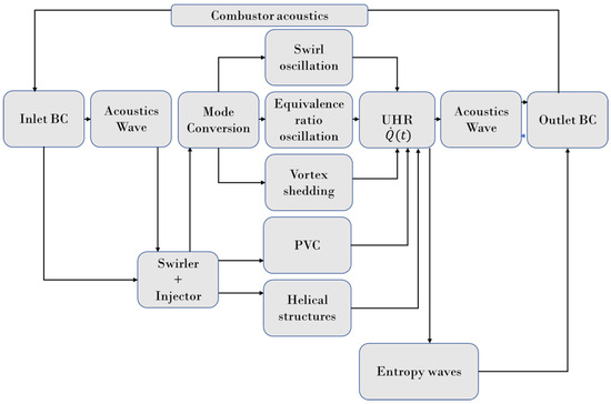
Figure 6.
Schematic of the interaction between the mechanisms possibly at work in a swirl-stabilized combustion chamber with or without hydrogen fuel.
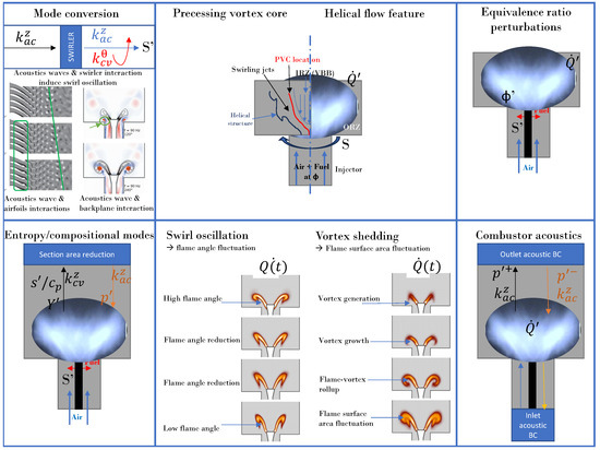
Figure 7.
Illustration of each individual mechanisms possibly involved in unsteady heat release for a swirl-stabilized combustion chamber. The figure includes the following: (1) the mode conversion process; (2) the precessing vortex core; (3) helical structures; (4) equivalence ratio perturbations; (5) entropy waves; (6) swirl oscillation; (7) vortex shedding from Palies doctoral thesis; and (8) combustor acoustics. The kinematic flame front for swirl flame is typically resulting in swirl oscillation and velocity fluctuations affecting the flame front and thus the unsteady heat release. At large amplitude, vortex rollup occurs.
These mechanisms may act independently or partly together as pointed out in Figure 6. In this schematic, the multiple paths towards combustion instability for swirl-stabilized systems are highlighted. In this schematic, the inlet and outlet BC represents both the mean flow and its fluctuating components. The acoustics wave generated or propagating from the upstream side of the injector interacts with the swirler/injector to generate unsteady heat release through the multiple mechanisms highlighted in Figure 7. These mechanisms include the one directly driven by the mode conversion: the swirl number oscillation. Vortex shedding and the equivalence ratio oscillation are also indirectly impacted by mode conversion process. The mechanism also includes the aerodynamics of the injector/combustor: PVC and helical structures.
The role of the mode conversion at the swirler is two-fold. First of all, the mode conversion is responsible for the swirl number oscillation controlling the IRZ size and thus the flame angle. The visualization of the flow velocity demonstrated that the IRZ is modulated both in shape and strength. Secondly, the mode conversion process occurring at the swirler enhances or not—depending on the frequency—the formation of the vortex at the injector backplane of the combustor because of the convective component of the resulting wave. Two sources of vorticity are identified: the first one exiting the swirler due to the first mode conversion process, and the second one due to interaction at the backplane.
5.5. Conclusions
Swirling flame dynamics has received considerable attention over the last decade. An open question regarding the role and the effect of the static flame front position would need to be examined. There is a relationship between the fluctuation of the swirl number and the burning flame speed ratio, and subsequently of the unsteady heat release. It should be examined further. The instantaneous flame surface transport (the flame surface element is burning as they are transported) in reacting swirling flows should also be investigated. Open questions also include the effect of turbulence on the mean (time-averaged) flame position, and the computation of the static flow component and its comparison with the time-averaged component. Being able to split static and dynamic flow components will also yield the respective roles of the mean and fluctuations in the flowfield in various processes.
6. Perspectives
This article comprehensively reviewed the literature on swirling flows, swirling flame dynamics, and the combustion instabilities of swirl-stabilized combustion systems. The key processes responsible for the unsteady heat release of premixed swirling flames were presented in detail. The perspectives of the present research are numerous and summarized now. There are three main categories of perspectives to this work.
First of all, future injector development enabling low NOx and low CO2 footprints should be researched. Major developments in injection systems design (flame stabilization, LBO, flashback) and modeling (supercritical fluid, chemical kinetics at high pressure and high temperature, fuel vaporization) are required to pursue the goal initiated on LPP/LPM injection systems, i.e., to reduce NOx. One of the main drawbacks of the technology developments carried out so far on these injection systems has been the fact that liquid fuel is not fully vaporized prior to premixing and does not enable the initial design intent of the LPP/LPM systems. Recent concepts for fully lean premixed combustion includes the LFP concept [341]. Its major advantage is that it has a heat exchanger unit with potential to enable fully premixed combustion in a gas turbine engine and to operate with hydrogen fuel.
Secondly, fundamental experimental and theoretical studies are needed. There is a requirement for additional studies to enhance the design of current and future technologies to address the challenges described in the introduction. There is a need for both theoretical and experimental work on the mode conversion processes and the identification of the mode of propagation of fluctuations. This includes convective and acoustic waves with the determination of their amplitudes, complex frequencies and speeds, and their spatial locations (for initiation, propagation, and damping), in order to enhance subsequent modeling. It is important because of the impact of these processes on the flame dynamics. The flame stabilization is another aspect that needs attention to enable future injection systems. The analytical framework for swirling flame stabilization by Palies and Premchand [81] and illustrated in Figure 8 should be extended to other configurations/setups, fuel mixtures, operating conditions, and operating regimes.
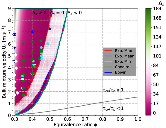
Figure 8.
Hydrogen–air premixed swirling flame stabilization map. Figure taken from [81].
Finally, numerical simulations, high-performance computing, and data processing should be undertaken further. As computational capabilities continue to grow, they will play a major role in design procedures and theoretical investigations. These will enable the computational domain to be extended to obtain more insights into the flowfield (including compressor exit stage or turbine inlet stage) and to model more geometrical details, as well as the global effect of the geometry on the flowfield. The flame speed should be extracted and assessed from these numerical simulations, as recently conducted for non-swirled premixed flames in Yahou et al. [342]. Data sciences and data mining, along with machine learning, could also be of use, for example, in the development of LES models using DNS data or to optimize fuel burn.
7. Conclusions
The present paper provided an overview of the state of the art, highlights the major advances, outlines the point of discussion in the literature, identifies gaps, and gives perspectives for future work. This review leads to a few major route recommendations: (i) the application and extension of the recent developed framework for flame stabilization is required; (ii) the development of the injection system and subsequent studies (upstream flame mixing processes and flame speed quantity) for fully premixed combustion are needed; and (iii) combustion physics discovery in swirling flames will be enhanced with advanced ultra-high-speed and high resolution experimental diagnostics and simulations enabling the capture of both swirler-induced turbulence and integral to Kolmogorov length scales. This paper also includes elements on non-reacting swirling flows, with an emphasis on vortex breakdown and hydrodynamics stability, turbulent combustion modeling, recent flame stabilization framework developed, lean blowout, flashback, and flame responses. The paper includes some of the recent advances made in hydrogen combustion for those topics.
Funding
This research received no external funding.
Conflicts of Interest
The author declare no conflicts of interest.
Abbreviations
| AIAA | American Institute of Aeronautics and Astronautics |
| APS | American Physical Society |
| ASME | American Society of Mechanical Engineers |
| CFD | Computational Fluid Dynamics |
| CPU | Central Processing Unit |
| DES | Detached Eddy Simulation |
| DNS | Direct Numerical Simulation |
| DMD | Dynamic Mode Decomposition |
| FTF | Flame Transfer Function |
| FDF | Flame Describing Function |
| IRZ | Inner Recirculation Zone |
| LDV | Laser Doppler Velocimetry |
| LES | Large-Eddy Simulation |
| LFP | Lean Fully Premixed |
| LIF | Laser Induced Fluorescence |
| LPP | Lean Premixed Pre-vaporized |
| NASA | National Aeronautics and Space Administration |
| PIV | Particle Imaging Velocimetry |
| PLIF | Planar Laser Induced Fluorescence |
| POD | Proper Orthogonal Decomposition |
| PTV | Particle Tracking Velocimetry |
| PVC | Precessing Vortex Core |
| RANS | Reynolds Averaged Navier–Stokes |
| RMS | Root Mean Square |
| VBB | Vortex Breakdown Bubble |
References
- UN. United Nations Paris Agreement. In Proceedings of the Report of the Conference of the Parties to the United Nations Framework Convention on Climate Change (21st Session, 2015: Paris), Paris, France, 12 December 2015; Volume 4. [Google Scholar]
- NASEM. Commercial Aircraft Propulsion and Energy Systems Research: Reducing Global Carbon Emissions; National Academies of Sciences, Engineering, and Medicine; National Academies Press: Washington, DC, USA, 2016. [Google Scholar]
- International Civil Aviation Organization (ICAO). Consolidated Statement of Continuing ICAO Policies and Practices Related to Environmental Protection-Carbon Offsetting and Reduction Scheme for International Aviation, 2022. Resolution A41-22 CORSIA.
- Beer, J.; Chigier, N. Combustion Aerodynamics; Elsevier Science: Amsterdam, The Netherlands, 1972. [Google Scholar]
- Gupta, A.; Lilley, D.; Syred, N. Swirl Flows; Abaqus Press: Hachette, UK, 1984. [Google Scholar]
- Syred, N.; Beer, J. Combustion in swirling flows: A review. Combust. Flame 1974, 23, 143–201. [Google Scholar] [CrossRef]
- Lilley, D. Swirl flows in combustion: A review. AIAA J. 1977, 15, 1065–1078. [Google Scholar] [CrossRef]
- Hall, M.G. Vortex Breakdown. Annu. Rev. Fluid Mech. 1972, 4, 195–218. [Google Scholar] [CrossRef]
- Leibovich, S. The Structure of Vortex Breakdown. Annu. Rev. Fluid Mech. 1978, 10, 221–246. [Google Scholar] [CrossRef]
- Escudier, M. Vortex breakdown: Observations and explanations. Prog. Aerosp. Sci. 1988, 25, 189–229. [Google Scholar] [CrossRef]
- Sloan, D.; Smith, P.; Smoot, L. Modeling of swirl in turbulent flow systems. Prog. Energy Combust. Sci. 1986, 12, 163–250. [Google Scholar] [CrossRef]
- McManus, K.R.; Poinsot, T.; Candel, S. A Review of Active Control of Combustion Instabilities. Prog. Energy Combust. Sci. 1993, 19, 1–29. [Google Scholar] [CrossRef]
- Lucca-Negro, O.; O’Doherty, T. Vortex breakdown: A review. Prog. Energy Combust. Sci. 2001, 27, 431–481. [Google Scholar] [CrossRef]
- Lieuwen, T.C.; Yang, V. (Eds.) Combustion instabilities in gas turbines, Operational experience, Fundamental mechanisms, and Modeling. In Progress in Astronautics and Aeronautics; American Institute of Aeronautics and Astronautics, Inc.: Reston, VA, USA, 2005; Volume 210. [Google Scholar]
- Syred, N. A review of oscillation mechanisms and the role of the precessing vortex core (PVC) in swirl combustion systems. Prog. Energy Combust. Sci. 2006, 32, 93–161. [Google Scholar] [CrossRef]
- Huang, Y.; Yang, V. Dynamics and stability of lean-premixed swirl-stabilized combustion. Prog. Energy Combust. Sci. 2009, 35, 293–384. [Google Scholar] [CrossRef]
- Lieuwen, T.C. Unsteady Combustor Physics; Cambridge University Press: Cambridge, UK, 2012. [Google Scholar]
- O’Connor, J.; Acharya, V.; Lieuwen, T. Transverse combustion instabilities: Acoustic, fluid mechanic, and flame processes. Prog. Energy Combust. Sci. 2015, 49, 1–39. [Google Scholar] [CrossRef]
- Gicquel, L.Y.; Staffelbach, G.; Poinsot, T. Large eddy simulations of gaseous flames in gas turbine combustion chambers. Prog. Energy Combust. Sci. 2012, 38, 782–817. [Google Scholar] [CrossRef]
- Candel, S.; Durox, D.; Schuller, T.; Palies, P.; Bourgouin, J.F.; Moeck, J.P. Progress and challenges in swirling flame dynamics. Comptes Rendus Mec. 2012, 340, 758–768. [Google Scholar] [CrossRef]
- Candel, S.; Durox, D.; Schuller, T.; Bourgouin, J.; Moeck, J. Dynamics of swirling flames. Annu. Rev. Fluid Mech. 2014, 46, 147–173. [Google Scholar] [CrossRef]
- Bauerheim, M.; Nicoud, F.; Poinsot, T. Progress in analytical methods to predict and control azimuthal combustion instability modes in annular chambers. Phys. Fluids 2016, 28, 021303. [Google Scholar] [CrossRef]
- Poinsot, T. Prediction and control of combustion instabilities in real engines. Proc. Combust. Inst. 2017, 36, 1–28. [Google Scholar] [CrossRef]
- Schuller, T.; Poinsot, T.; Candel, S. Dynamics and control of premixed combustion systems based on flame transfer and describing functions. J. Fluid Mech. 2020, 894, 1. [Google Scholar] [CrossRef]
- Polifke, W. Modeling and analysis of premixed flame dynamics by means of distributed time delays. Prog. Energy Combust. Sci. 2020, 79, 100845. [Google Scholar] [CrossRef]
- Silva, C.F. Intrinsic thermoacoustic instabilities. Prog. Energy Combust. Sci. 2023, 95, 101065. [Google Scholar] [CrossRef]
- Palies, P. Stabilization and Dynamic of Premixed Swirling Flames: Prevaporized, Stratified, Partially, and Fully Premixed Regimes; Academic Press: Cambridge, MA, USA, 2020. [Google Scholar]
- Palies, P.; Ilak, M.; Cheng, R. Transient and limit cycle combustion dynamics analysis of turbulent premixed swirling flame. J. Fluid Mech. 2017, 830, 681–707. [Google Scholar] [CrossRef]
- Vignat, G.; Durox, D.; Candel, S. The suitability of different swirl number definitions for describing swirl flows: Accurate, common and (over-) simplified formulations. Prog. Energy Combust. Sci. 2022, 89, 100969. [Google Scholar] [CrossRef]
- Billant, P.; Chomaz, J.; Huerre, P. Experimental study of vortex breakdown in swirling jets. J. Fluid Mech. 1998, 376, 183–219. [Google Scholar] [CrossRef]
- Sarpkaya, T. An Experimental Investigation of the Vortex-Breakdown Phenomenon; Technical Report NPS-59SL007IA; United States Naval Postgraduate School: Monterey, CA, USA, 1970. [Google Scholar]
- Chigier, N.; Beer, J. Velocity and static-pressure distributions in swirling air jets issuing from annular and divergent nozzles. J. Basic Eng. 1964, 86, 788–796. [Google Scholar] [CrossRef]
- Oberleithner, K.; Sieber, M.; Nayeri, C.; Paschereit, C.; Petz, C.; Hege, H.C.; Noack, B.; Wygnanski, I. Three-dimensional coherent structures in a swirling jet undergoing vortex breakdown: Stability analysis and empirical mode construction. J. Fluid Mech. 2011, 679, 383–414. [Google Scholar] [CrossRef]
- Benjamin, T.B. Theory of the vortex breakdown phenomenon. J. Fluid Mech. 1962, 14, 593–629. [Google Scholar] [CrossRef]
- Harvey, J.K. Some observations of the vortex breakdown phenomenon. J. Fluid Mech. 1962, 14, 585–592. [Google Scholar] [CrossRef]
- Delery, J.M. Aspects of vortex breakdown. Prog. Aerosp. Sci. 1994, 30, 1–59. [Google Scholar] [CrossRef]
- Shtern, V.; Hussain, F. Collapse, symmetry breaking, and hysteresis in swirling flows. Annu. Rev. Fluid Mech. 1999, 31, 537–566. [Google Scholar] [CrossRef]
- Sarpkaya, T. On stationary and travelling vortex breakdowns. J. Fluid Mech. 1971, 45, 545–559. [Google Scholar] [CrossRef]
- Faler, J.H.; Leibovich, S. Disrupted states of vortex flow and vortex breakdown. Phys. Fluids 1977, 20, 1385–1400. [Google Scholar] [CrossRef]
- Gelfgat, A.Y.; Bar-Yoseph, P.; Solan, A. Stability of confined swirling flow with and without vortex breakdown. J. Fluid Mech. 1996, 311, 1–36. [Google Scholar] [CrossRef]
- Faler, J.H.; Leibovich, S. An experimental map of the internal structure of a vortex breakdown. J. Fluid Mech. 1978, 86, 313–335. [Google Scholar] [CrossRef]
- Brücker, C.; Althaus, W. Study of vortex breakdown by particle tracking velocimetry (PTV). Part 1: Bubble-type vortex breakdown. Exp. Fluids 1992, 13, 339–349. [Google Scholar] [CrossRef]
- Brücker, C.; Althaus, W. Study of vortex breakdown by particle tracking velocimetry (PTV). Part 2: Spiral-type vortex breakdown. Exp. Fluids 1993, 14, 133–139. [Google Scholar] [CrossRef]
- Brücker, C.; Althaus, W. Study of vortex breakdown by particle tracking velocimetry (PTV). Part 3: Time-dependent structure and development of breakdown-modes. Exp. Fluids 1995, 18, 174–186. [Google Scholar] [CrossRef]
- Panda, J.; McLaughlin, D. Experiments on the instabilities of a swirling jet. Phys. Fluids 1994, 6, 263–276. [Google Scholar] [CrossRef]
- Vanierschot, M.; Van den Bulck, E. Influence of swirl on the initial merging zone of a turbulent annular jet. Phys. Fluids 2008, 20, 105104. [Google Scholar] [CrossRef]
- Vanierschot, M.; Van den Bulck, E. Experimental study of low precessing frequencies in the wake of a turbulent annular jet. Exp. Fluids 2011, 50, 189–200. [Google Scholar] [CrossRef]
- Vanierschot, M.; Van Dyck, K.; Sas, P.; Van den Bulck, E. Symmetry breaking and vortex precession in low-swirling annular jets. Phys. Fluids 2014, 26, 105110. [Google Scholar] [CrossRef]
- Santhosh, R.; Miglani, A.; Basu, S. Transition in vortex breakdown modes in a coaxial isothermal unconfined swirling jet. Phys. Fluids 2014, 26, 043601. [Google Scholar] [CrossRef]
- Percin, M.; Vanierschot, M.; Oudheusden, B.W.v. Analysis of the pressure fields in a swirling annular jet flow. Exp. Fluids 2017, 58, 166. [Google Scholar] [CrossRef]
- Xi, Z.; Liu, Z.; Shi, X.; Lian, T.; Li, Y. Numerical investigation on flow characteristics and emissions under varying swirler vane angle in a lean premixed combustor. Case Stud. Therm. Eng. 2022, 31, 101800. [Google Scholar] [CrossRef]
- Ramos, J.; Somer, H. Swirling flow in a research combustor. AIAA J. 1985, 23, 241–248. [Google Scholar] [CrossRef]
- Dellenback, P.; Metzger, D.; Neitzel, G. Measurements in turbulent swirling flow through an abrupt axisymmetric expansion. AIAA J. 1988, 26, 669–681. [Google Scholar] [CrossRef]
- Wang, P.; Bai, X.; Wessman, M.; Klingmann, J. Large eddy simulation and experimental studies of a confined turbulent swirling flow. Phys. Fluids 2004, 16, 3306–3324. [Google Scholar] [CrossRef]
- Escudier, M.; Keller, J. Recirculation in swirling flow—A manifestation of vortex breakdown. AIAA J. 1985, 23, 111–116. [Google Scholar] [CrossRef]
- Lilley, D. Swirling flows in typical combustor geometries. J. Propuls. Power 1986, 2, 64–72. [Google Scholar] [CrossRef]
- Graftieaux, L.; Michard, M.; Grosjean, N. Combining PIV, POD and vortex identification algorithms for the study of unsteady turbulent swirling flows. Meas. Sci. Technol. 2001, 12, 1422. [Google Scholar] [CrossRef]
- Mak, H.; Balabani, S. Near field characteristics of swirling flow past a sudden expansion. Chem. Eng. Sci. 2007, 62, 6726–6746. [Google Scholar] [CrossRef]
- Cala, C.E.; Fernandes, E.C.; Heitor, M.V.; Shtork, S.I. Coherent structures in unsteady swirling jet flow. Exp. Fluids 2006, 40, 267–276. [Google Scholar] [CrossRef]
- Liang, H.; Maxworthy, T. An experiment investigation of swirling jets. J. Fluid Mech. 2005, 525, 115–159. [Google Scholar] [CrossRef]
- Loiseleux, T.; Chomaz, J.M. Breaking of rotational symmetry in a swirling jet experiment. Phys. Fluids 2003, 15, 511–523. [Google Scholar] [CrossRef]
- Squire, H. Analysis of the Vortex Breakdown Phenomenon; Imperial College of Science and Technology, Aeronautics Department: London, UK, 1960. [Google Scholar]
- Benjamin, T.B. Some developments in the theory of vortex breakdown. J. Fluid Mech. 1967, 28, 65–84. [Google Scholar] [CrossRef]
- Wang, S.; Rusak, Z. The dynamics of a swirling flow in a pipe and transition to axisymmetric vortex breakdown. J. Fluid Mech. 1997, 340, 177–223. [Google Scholar] [CrossRef]
- Oberleithner, K.; Paschereit, C.; Seele, R.; Wygnanski, I. Formation of turbulent vortex breakdown: Intermittency, criticality, and global instability. AIAA J. 2012, 50, 1437–1452. [Google Scholar] [CrossRef]
- Lessen, M.; Singh, P.; Paillet, F. The stability of a trailing line vortex. Part 1. Inviscid theory. J. Fluid Mech. 1974, 63, 753–763. [Google Scholar] [CrossRef]
- Lessen, M.; Paillet, F. The stability of a trailing line vortex. Part 2. Viscous theory. J. Fluid Mech. 1974, 65, 769–779. [Google Scholar] [CrossRef]
- Martin, J.; Meiburg, E. On the stability of the swirling jet shear layer. Phys. Fluids 1994, 6, 424–426. [Google Scholar] [CrossRef][Green Version]
- Loiseleux, T.; Chomaz, J.; Huerre, P. The effect of swirl on jets and wakes: Linear instability of the Rankine vortex with axial flow. Phys. Fluids 1998, 10, 1120–1134. [Google Scholar] [CrossRef]
- Loiseleux, T.; Delbende, I.; Huerre, P. Absolute and convective instabilities of a swirling jet/wake shear layer. Phys. Fluids 2000, 12, 375–380. [Google Scholar] [CrossRef]
- Gallaire, F.; Chomaz, J.M. Instability mechanisms in swirling flows. Phys. Fluids 2003, 15, 2622–2639. [Google Scholar] [CrossRef]
- Oberleithner, K.; Paschereit, C.; Wygnanski, I. On the impact of swirl on the growth of coherent structures. J. Fluid Mech. 2014, 741, 156–199. [Google Scholar] [CrossRef]
- Tammisola, O.; Juniper, M.P. Coherent structures in a swirl injector at Re = 4800 by nonlinear simulations and linear global modes. J. Fluid Mech. 2016, 792, 620–657. [Google Scholar] [CrossRef]
- Vyas, A.B.; Majdalani, J. Exact solution of the bidirectional vortex. AIAA J. 2006, 44, 2208–2216. [Google Scholar] [CrossRef]
- Smith, F.T. On the non-parallel flow stability of the Blasius boundary layer. Proc. R. Soc. Lond. A Math. Phys. Sci. 1979, 366, 91–109. [Google Scholar]
- Moise, P. Bistability of bubble and conical forms of vortex breakdown in laminar swirling jets. J. Fluid Mech. 2020, 889. [Google Scholar] [CrossRef]
- Rusak, Z.; Wang, S.; Xu, L.; Taylor, S. On the global nonlinear stability of a near-critical swirling flow in a long finite-length pipe and the path to vortex breakdown. J. Fluid Mech. 2012, 712, 295–326. [Google Scholar] [CrossRef]
- Rusak, Z.; Choi, J.J.; Bourquard, N.; Wang, S. Vortex breakdown of compressible subsonic swirling flows in a finite-length straight circular pipe. J. Fluid Mech. 2015, 781, 3. [Google Scholar] [CrossRef]
- Palies, P. The Flame Surface Speed Budget for Turbulent Premixed Flame Stabilization Studies. In Proceedings of the AIAA Scitech 2020 Forum, Orlando, FL, USA, 6–10 January 2020. [Google Scholar]
- Palies, P. The flame displacement speed: A key quantity for turbulent combustion and combustion instability. Int. J. Spray Combust. Dyn. 2022, 14, 4–16. [Google Scholar] [CrossRef]
- Palies, P.; Premchand, C. Hydrogen-air lean premixed turbulent highly swirled flames stabilization: Experimental demonstration and mechanistic-kinematic description. Aeronaut. J. 2025, 1–24. [Google Scholar] [CrossRef]
- Chu, B.T.; Kovásznay, L.S. Non-linear interactions in a viscous heat-conducting compressible gas. J. Fluid Mech. 1958, 3, 494–514. [Google Scholar] [CrossRef]
- Noiray, N.; Durox, D.; Schuller, T.; Candel, S. Mode conversion in acoustically modulated confined jets. AIAA J. 2009, 47, 2053–2062. [Google Scholar] [CrossRef]
- Komarek, T.; Polifke, W. Impact of swirl fluctuations on the flame response of a perfectly premixed swirl burner. J. Eng. Gas Turbine Power 2010, 132, 061503. [Google Scholar] [CrossRef]
- Palies, P.; Durox, D.; Schuller, T.; Candel, S. Acoustic-convective mode conversion in an aerofoil cascade. J. Fluid Mech. 2011, 672, 545–569. [Google Scholar] [CrossRef]
- Richards, G.; Yip, M. Oscillation combustion from a premix fuel nozzle. In Proceedings of the Combustion Institute/American Flame Research Committee Meeting, San Antonio, TX, USA, 23–26 April 1995. [Google Scholar]
- Straub, D.L.; Richards, G.A. Effect of fuel nozzle configuration on premix combustion dynamics. In Proceedings of the International Gas Turbine & Aeroengine Congress & Exhibition, Stockholm, Sweden, 2–5 June 1998; American Society of Mechanical Engineers: New York, NY, USA, 1998; Volume 78644, p. V003T06A044. [Google Scholar]
- Straub, D.; Richards, G. Effect of axial swirl vane location on combustion dynamics. In Proceedings of the ASME 1999 International Gas Turbine and Aeroengine Congress and Exhibition, Indianapolis, IN, USA, 7–10 June 1999; Volume 99-GT-109. [Google Scholar]
- Palies, P. Dynamique et Instabilités de Combustion des Flammes Swirlées. Ph.D. Thesis, Ecole Centrale Paris, Gif-sur-Yvette, France, 2010. [Google Scholar]
- Bunce, N.A. Flame Transfer Function Measurements and Mechanisms in a Single-Nozzle Combustor. Ph.D. Thesis, Penn State University, University Park, PA, USA, 2013. [Google Scholar]
- Albayrak, A. Time Scales of Equivalence Ratio and Inertial Waves in Unsteady Combustion Dynamics. Ph.D. Thesis, Technische Universität München, München, Germany, 2019. [Google Scholar]
- Albayrak, A.; Juniper, M.P.; Polifke, W. Propagation speed of inertial waves in cylindrical swirling flows. J. Fluid Mech. 2019, 879, 85–120. [Google Scholar] [CrossRef]
- Markstein, G.H. Nonsteady Flame Propagation; Elsevier: Amsterdam, The Netherlands, 1964; Volume 75. [Google Scholar]
- Darmofal, D.L. The role of vorticity dynamics in vortex breakdown. In Proceedings of the 23rd Fluid Dynamics, Plasmadynamics, and Lasers Conference, Orlando, FL, USA, 6–9 July 1993. AIAA-93-3036. [Google Scholar]
- Martin, J.; Meiburg, E. The growth and nonlinear evolution of helical perturbations in a swirling jet model. Eur. J. Mech.-B/Fluids 1998, 17, 639–651. [Google Scholar] [CrossRef]
- Grinstein, F.F.; Young, T.R.; Li, G.; Gutmark, E.; Hsiao, G.; Mongia, H.C. Flow Dynamics in a Swirling Jet Combustor; Begel House Inc.: Danbury, CT, USA, 2001. [Google Scholar]
- Kilik, E. The Influence of Swirler Design Parameters on the Aerodynamics of Downstream Recirculation Region. Ph.D. Thesis, Cranfield University, Bedford, UK, 1976. [Google Scholar]
- Raj, R.T.K.; Ganesan, V. Study on the effect of various parameters on flow development behind vane swirlers. Int. J. Therm. Sci. 2008, 47, 1204–1225. [Google Scholar]
- He, C.; Gan, L.; Liu, Y. The formation and evolution of turbulent swirling vortex rings generated by axial swirlers. Flow Turbul. Combust. 2020, 104, 795–816. [Google Scholar] [CrossRef]
- Nikjooy, M.; Mongia, H. A second-order modeling study of confined swirling flow. Int. J. Heat Fluid Flow 1991, 12, 12–19. [Google Scholar] [CrossRef]
- Kubo, I.; Gouldin, F. Numerical calculations of turbulent swirling flow. J. Fluids Eng. 1975, 97, 310–315. [Google Scholar] [CrossRef]
- Sharif, M.; Wong, Y. Evaluation of the performance of three turbulence closure models in the prediction of confined swirling flows. Comput. Fluids 1995, 24, 81–100. [Google Scholar] [CrossRef]
- Jakirlic, S.; Hanjalic, K.; Tropea, C. Modeling rotating and swirling turbulent flows: A perpetual challenge. AIAA J. 2002, 40, 1984–1996. [Google Scholar] [CrossRef]
- Favaloro, S.; Nejad, A.; Ahmed, S. Experimental and computational investigation of isothermal swirling flow in an axisymmetric dump combustor. J. Propuls. Power 1991, 7, 348–356. [Google Scholar] [CrossRef]
- Leschziner, M.A.; Hogg, S. Computation of highly swirling confined flow with a Reynolds stress turbulence model. AIAA J. 1989, 27, 57–63. [Google Scholar] [CrossRef]
- Dong, M.; Lilley, D.G. Inlet velocity profile effects on turbulent swirling flow predictions. J. Propuls. Power 1994, 10, 155–160. [Google Scholar] [CrossRef]
- Xia, J.; Smith, B.; Benim, A.; Schmidli, J.; Yadigaroglu, G. Effect of inlet and outlet boundary conditions on swirling flows. Comput. Fluids 1997, 26, 811–823. [Google Scholar] [CrossRef]
- Ahmed, S.A. Velocity measurements and turbulence statistics of a confined isothermal swirling flow. Exp. Therm. Fluid Sci. 1998, 17, 256–264. [Google Scholar] [CrossRef]
- Palies, P.; Acharya, R. Flame-resolved transient simulation with swirler-induced turbulence applied to lean blowoff premixed flame experiment. Combust. Flame 2021, 226, 14–30. [Google Scholar] [CrossRef]
- Lu, X.; Wang, S.; Sung, H.; Hsieh, S.; Yang, V. Large-eddy simulations of turbulent swirling flows injected into a dump chamber. J. Fluid Mech. 2005, 527, 171–195. [Google Scholar] [CrossRef]
- Wang, S.; Hsieh, S.; Yang, V. Unsteady flow evolution in swirl injector with radial entry. I. Stationnary conditions. Phys. Fluids 2005, 17, 045106. [Google Scholar] [CrossRef]
- Wang, S.; Yang, V. Unsteady flow evolution in swirl injector with radial entry. II. External excitations. Phys. Fluids 2005, 17, 045107. [Google Scholar] [CrossRef]
- Wang, S.; Yang, V.; Hsiao, G.; Hsieh, S.Y.; Mongia, H. Large-eddy simulations of gas-turbine swirl injector flow dynamics. J. Fluid Mech. 2007, 583, 99–122. [Google Scholar] [CrossRef]
- Duwig, C.; Fuchs, L.; Lacarelle, A.; Beutke, M.; Paschereit, C.O. Study of the vortex breakdown in a conical swirler using LDV, LES and POD. In Proceedings of the ASME Turbo Expo 2007: Power for Land, Sea, and Air, Montreal, QC, Canada, 14–17 May 2007; American Society of Mechanical Engineers: New York, NY, USA, 2007; pp. 1–10. [Google Scholar]
- Stone, C.; Menon, S. Swirl control of combustion instabilities in a gas turbine combustor. Proc. Combust. Inst. 2002, 29, 155–160. [Google Scholar] [CrossRef]
- Javadi, A.; Nilsson, H. LES and DES of strongly swirling turbulent flow through a suddenly expanding circular pipe. Comput. Fluids 2015, 107, 301–313. [Google Scholar] [CrossRef]
- Wang, Y.; Wang, X.; Yang, V. Evolution and transition mechanisms of internal swirling flows with tangential entry. Phys. Fluids 2018, 30, 013601. [Google Scholar] [CrossRef]
- Ruith, M.; Chen, P.; Meiburg, E.; Maxworthy, T. Three-dimensional vortex breakdown in swirling jets and wakes: Direct numerical simulation. J. Fluid Mech. 2003, 486, 331–378. [Google Scholar] [CrossRef]
- Freitag, M.; Klein, M. Direct Numerical Simulation of a Recirculating, Swirling Flow. Flow Turbul. Combust. 2005, 75, 51–66. [Google Scholar] [CrossRef]
- Shamami, K.K.; Birouk, M. Assessment of the performances of RANS models for simulating swirling flows in a can-combustor. Open Aerosp. Eng. J. 2008, 1, 8–27. [Google Scholar] [CrossRef]
- Gouldin, F.; Depsky, J.; Lee, S. Velocity field characteristics of a swirling flow combustor. AIAA J. 1983, 23, 95–102. [Google Scholar] [CrossRef]
- Gouldin, F.; Halthore, R.; Vu, B. Periodic oscillations observed in swirling flows with and without combustion. Symp. (Int.) Combust. 1985, 20, 269–276. [Google Scholar] [CrossRef]
- Brum, R.D.; Samuelsen, G.S. Two-component laser anemometry measurements of non-reacting and reacting complex flows in a swirl-stabilized model combustor. Exp. Fluids 1987, 5, 95–102. [Google Scholar] [CrossRef]
- Roux, S.; Lartigue, G.; Poinsot, T.; Berat, T. Studies of mean and unsteady flow in a swirled combustor using experiments, acoustic analysis and large eddy simulations. Combust. Flame 2005, 141, 40–54. [Google Scholar] [CrossRef]
- Schneider, C.; Dreizler, A.; Janicka, J. Fluid Dynamical Analysis of Atmospheric Reacting and Isothermal Swirling Flows. Flow Turbul. Combust. 2005, 74, 103–127. [Google Scholar] [CrossRef]
- Beneddine, S.; Sipp, D.; Arnault, A.; Dandois, J.; Lesshafft, L. Conditions for validity of mean flow stability analysis. J. Fluid Mech. 2016, 798, 485–504. [Google Scholar] [CrossRef]
- Karban, U.; Bugeat, B.; Martini, E.; Towne, A.; Cavalieri, A.; Lesshafft, L.; Agarwal, A.; Jordan, P.; Colonius, T. Ambiguity in mean-flow-based linear analysis. J. Fluid Mech. 2020, 900, R5. [Google Scholar] [CrossRef]
- Rusak, Z.; Kapila, A.; Choi, J.J. Effect of combustion on near-critical swirling flow. Combust. Theory Model. 2002, 6, 625–645. [Google Scholar] [CrossRef]
- Oberleithner, K.; Schimek, S.; Paschereit, C.O. Shear flow instabilities in swirl-stabilized combustors and their impact on the amplitude dependent flame response: A linear stability analysis. Combust. Flame 2015, 162, 86–99. [Google Scholar] [CrossRef]
- Umeh, C.O.; Rusak, Z.; Gutmark, E. Vortex breakdown in a swirl-stabilized combustor. J. Propuls. Power 2012, 28, 1037–1051. [Google Scholar] [CrossRef]
- Taamallah, S.; LaBry, Z.; Shanbhogue, S.; Habib, M.; Ghoniem, A. Correspondence Between Stable Flame Macrostructure and Thermo-acoustic Instability in Premixed Swirl-Stabilized Turbulent Combustion. J. Eng. Gas Turbines Power 2015, 137, 071505. [Google Scholar] [CrossRef]
- Meier, W.; Weigand, P.; Duan, X.R.; Giezendanner-Thoben, R. Detailed characterization of the dynamics of thermoacoustic pulsations in a lean premixed swirl flame. Combust. Flame 2007, 150, 2–26. [Google Scholar] [CrossRef]
- Steinberg, A.M.; Arndt, C.M.; Meier, W. Parametric study of vortex structures and their dynamics in swirl-stabilized combustion. Proc. Combust. Inst. 2013, 34, 3117–3125. [Google Scholar] [CrossRef]
- O’Connor, J. Visualization of shear layer dynamics in a transversely forced flow and flame. J. Propuls. Power 2015, 31, 1127–1136. [Google Scholar] [CrossRef]
- Steinberg, A.M.; Boxx, I.; Stohr, M.; Meier, W.; Carter, C.D. Effects of flow structure dynamics on thermoacoustic instabilities in swirl-stabilized combustion. AIAA J. 2012, 50, 952–967. [Google Scholar] [CrossRef]
- Moeck, J.P.; Bourgouin, J.F.; Durox, D.; Schuller, T.; Candel, S. Nonlinear interaction between a precessing vortex core and acoustic oscillations in a turbulent swirling flame. Combust. Flame 2012, 159, 2650–2668. [Google Scholar] [CrossRef]
- Oberleithner, K.; Stöhr, M.; Im, S.H.; Arndt, C.M.; Steinberg, A.M. Formation and flame-induced suppression of the precessing vortex core in a swirl combustor: Experiments and linear stability analysis. Combust. Flame 2015, 162, 3100–3114. [Google Scholar] [CrossRef]
- An, Q.; Kwong, W.Y.; Geraedts, B.D.; Steinberg, A.M. Coupled dynamics of lift-off and precessing vortex core formation in swirl flames. Combust. Flame 2016, 168, 228–239. [Google Scholar] [CrossRef]
- Taamallah, S.; Dagan, Y.; Chakroun, N.; Shanbhogue, S.; Vogiatzaki, K.; Ghoniem, A.F. Helical vortex core dynamics and flame interaction in turbulent premixed swirl combustion: A combined experimental and large eddy simulation investigation. Phys. Fluids 2019, 31, 025108. [Google Scholar] [CrossRef]
- Zhang, R.; Boxx, I.; Meier, W.; Slabaugh, C.D. Coupled interactions of a helical precessing vortex core and the central recirculation bubble in a swirl flame at elevated power density. Combust. Flame 2019, 202, 119–131. [Google Scholar] [CrossRef]
- Chterev, I.; Emerson, B.; Lieuwen, T. Velocity and stretch characteristics at the leading edge of an aerodynamically stabilized flame. Combust. Flame 2018, 193, 92–111. [Google Scholar] [CrossRef]
- Roy, S.; Yi, T.; Jiang, N.; Gunaratne, G.; Chterev, I.; Emerson, B.; Lieuwen, T.; Caswell, A.; Gord, J. Dynamics of robust structures in turbulent swirling reacting flows. J. Fluid Mech. 2017, 816, 554–585. [Google Scholar] [CrossRef]
- Douglas, C.; Lim, J.; Smith, T.; Emerson, B.; Lieuwen, T.; Jiang, N.; Fugger, C.; Yi, T.; Felver, J.; Roy, S.; et al. Measurements of periodic reynolds stress oscillations in a forced turbulent premixed swirling flame. J. Eng. Gas Turbines Power 2019, 141, 011001. [Google Scholar] [CrossRef]
- Kazbekov, A.; Kumashiro, K.; Steinberg, A.M. Enstrophy transport in swirl combustion. J. Fluid Mech. 2019, 876, 715–732. [Google Scholar] [CrossRef]
- Kazbekov, A.; Steinberg, A.M. Physical space analysis of cross-scale turbulent kinetic energy transfer in premixed swirl flames. Combust. Flame 2021, 229, 111403. [Google Scholar] [CrossRef]
- Luckoff, F.; Sieber, M.; Paschereit, C.O.; Oberleithner, K. Impact of the Precessing Vortex Core on NOx Emissions in Premixed Swirl Stabilized Flames: An Experimental Study. J. Eng. Gas Turbines Power 2020, 142, 111010. [Google Scholar] [CrossRef]
- Garcia, A.M.; Le Bras, S.; Prager, J.; Boxx, I.; Polifke, W. Impact of H2-enrichment on the response of a partially premixed CH4–air flame to velocity and equivalence ratio fluctuations. Combust. Flame 2024, 268, 113595. [Google Scholar] [CrossRef]
- Lartigue, G.; Meier, U.; Berat, C. Experimental and numerical investigation of self-excited combustion oscillations in a scaled gas turbine combustor. Appl. Therm. Eng. 2004, 24, 1583–1592. [Google Scholar] [CrossRef]
- Salaün, E.; Malbois, P.; Vandel, A.; Godard, G.; Grisch, F.; Renou, B.; Cabot, G.; Boukhalfa, A. Experimental investigation of a spray swirled flame in gas turbine model combustor. In Proceedings of the 18th International Symposium on the Application of Laser and Imaging Techniques to Fluid Mechanics, Lisbon, Portugal, 4–7 July 2016. [Google Scholar]
- Weigand, P.; Meier, W.; Duan, X.; Stricker, W.; Aigner, M. Investigations of swirl flames in a gas turbine model combustor I. Flow field, structures, temperature, and species distributions. Combust. Flame 2006, 144, 205–224. [Google Scholar] [CrossRef]
- Chterev, I.; Rock, N.; Ek, H.; Emerson, B.; Seitzman, J.; Jiang, N.; Roy, S.; Lee, T.; Gord, J.; Lieuwen, T. Simultaneous imaging of fuel, OH, and three component velocity fields in high pressure, liquid fueled, swirl stabilized flames at 5 kHz. Combust. Flame 2017, 186, 150–165. [Google Scholar] [CrossRef]
- Cheng, R.; Yegian, D.; Miyasato, M.; Samuelsen, G.; Benson, C.; Pellizzari, R.; Loftus, P. Scaling and development of low-swirl burners for low-emission furnaces and boilers. Proc. Combust. Inst. 2000, 28, 1305–1313. [Google Scholar] [CrossRef]
- Cheng, R.; Littlejohn, D.; Nazeer, W.; Smith, K. Laboratory Studies of the Flow Field Characteristics of Low-Swirl Injectors for Application to Fuel-Flexible Turbines. J. Eng. Gas Turbines Power 2008, 130, 21501–21511. [Google Scholar] [CrossRef]
- Chan, C.; Lau, K.; Chin, W.; Cheng, R. Freely Propagating Open Premixed Turbulent Flames Stabilized by Swirl. Proc. Combust. Inst. 2005, 24, 511–518. [Google Scholar] [CrossRef]
- Cheng, R.K. Velocity and scalar characteristics of premixed turbulent flames stabilized by weak swirl. Combust. Flame 2005, 101, 1–14. [Google Scholar] [CrossRef]
- Therkelsen, P.; Enrique Portillo, J.; Littlejohn, D.; Martin, S.; Cheng, R. Self-induced unstable behaviors of CH4 and H2/CH4 flames in a model combustor with a low-swirl injector. Combust. Flame 2013, 160, 307–321. [Google Scholar] [CrossRef]
- Taamallah, S.; LaBry, Z.A.; Shanbhogue, S.J.; Ghoniem, A.F. Thermo-acoustic instabilities in lean premixed swirl-stabilized combustion and their link to acoustically coupled and decoupled flame macrostructures. Proc. Combust. Inst. 2015, 35, 3273–3282. [Google Scholar] [CrossRef]
- Bellows, B.D.; Bobba, M.K.; Forte, A.; Seitzman, J.M.; Lieuwen, T. Flame transfer function saturation mechanisms in a swirl-stabilized combustor. Proc. Combust. Inst. 2007, 31, 3181–3188. [Google Scholar] [CrossRef]
- Thumuluru, S.; Lieuwen, T. Characterization of acoustically forced swirl flame dynamics. Proc. Combust. Inst. 2009, 32, 2893–2900. [Google Scholar] [CrossRef]
- O’Connor, J.; Lieuwen, T. Disturbance Field Characteristics of a Transversely Excited Burner. Combust. Sci. Technol. 2011, 183, 427–443. [Google Scholar] [CrossRef]
- Bourgouin, J.F.; Durox, D.; Moeck, J.; Schuller, T.; Candel, S. Self-Sustained Instabilities in an Annular Combustor Coupled by Azimuthal and Longitudinal Acoustic Modes. In Proceedings of the ASME Turbo Expo GT2013-95010, San Antonio, TX, USA, 3–7 June 2013. [Google Scholar]
- Vignat, G. Injection and Combustion Dynamics in Swirled Spray Flames and Azimuthal Coupling in Annular Combustors. Ph.D. Thesis, Université Paris-Saclay, Gif-sur-Yvette, France, 2020. [Google Scholar]
- Stopper, U.; Meier, W.; Sadanandan, R.; Stöhr, M.; Aigner, M.; Bulat, G. Experimental study of industrial gas turbine flames including quantification of pressure influence on flow field, fuel/air premixing and flame shape. Combust. Flame 2013, 160, 2103–2118. [Google Scholar] [CrossRef]
- Bulat, G.; Fedina, E.; Fureby, C.; Meier, W.; Stopper, U. Reacting flow in an industrial gas turbine combustor: LES and experimental analysis. Proc. Combust. Inst. 2015, 35, 3175–3183. [Google Scholar] [CrossRef]
- Dawson, J.; Rodriguez-Martinez, V.; Syred, N.; O’Doherty, T. The effect of combustion instability on the structure of recirculation zones in confined swirling flames. Combust. Sci. Technol. 2005, 177, 2349–2371. [Google Scholar] [CrossRef]
- Richecoeur, F.; Schuller, T.; Lamraoui, A.; Ducruix, S. Analytical and experimental investigations of gas turbine model combustor acoustics operated at atmospheric pressure. Comptes Rendus Mécanique 2013, 341, 141–151. [Google Scholar] [CrossRef]
- Hermeth, S. Mechanisms Affecting the Dynamic Response of Swirled Flames in Gas Turbines. Ph.D. Thesis, INPT, Rabat, Morocco, 2012. [Google Scholar]
- Cochet, A.; Bodoc, V.; Brossard, C.; Dessornes, O.; Guin, C.; Lecourt, R.; Orain, M.; Vincent-Randonnier, A. ONERA test Facilities for Combustion in Aero Gas Turbine Engines, and Associated Optical Diagnostics. J. Aerosp. Lab 2016, 11, 16. [Google Scholar]
- Biagioli, F.; Gösthe, F.; Schuermans, B. Combustion dynamics linked to flame behaviour in a partially premixed swirled industrial burner. Exp. Therm. Fluid Sci. 2008, 32, 1344–1353. [Google Scholar] [CrossRef]
- Chterev, I.; Foley, C.W.; Foti, D.; Kostka, S.; Caswell, A.W.; Jiang, N.; Lynch, A.; Noble, D.R.; Menon, S.; Seitzman, J.M.; et al. Flame and Flow Topologies in an Annular Swirling Flow. Combust. Sci. Technol. 2014, 186, 1041–1074. [Google Scholar] [CrossRef]
- Bellows, B.D.; Neumeier, Y.; Lieuwen, T. Forced response of a swirling, premixed flame to flow disturbances. J. Propuls. Power 2006, 22, 1075–1084. [Google Scholar] [CrossRef]
- Schuermans, B.; Guethe, F.; Pennell, D.; Guyot, D.; Paschereit, C. Thermoacoustic modeling of a gas turbine using transfer functions measured under full engine pressure. J. Eng. Gas Turbines Power 2010, 132, 111503. [Google Scholar] [CrossRef]
- Dhanuka, S.; Temme, J.; Driscoll, J. Unsteady Aspects of Lean Premixed Prevaporized Gas Turbine Combustors: Flame-Flame Interactions. J. Propuls. Power 2011, 27, 631–641. [Google Scholar] [CrossRef]
- Williams, T.C.; Schefer, R.W.; Oefelein, J.C.; Shaddix, C.R. Idealized gas turbine combustor for performance research and validation of large eddy simulations. Rev. Sci. Instrum. 2007, 78, 035114. [Google Scholar] [CrossRef]
- Di Sabatino, F.; Guiberti, T.; Boyette, W.; Roberts, W.; Moeck, J.; Lacoste, D. Effect of pressure on the transfer functions of premixed methane and propane swirl flames. Combust. Flame 2018, 193, 272–282. [Google Scholar] [CrossRef]
- Schimek, S.; Moeck, J.P.; Paschereit, C.O. An experimental investigation of the nonlinear response of an atmospheric swirl-stabilized premixed flame. J. Eng. Gas Turbines Power 2011, 133, 101502. [Google Scholar] [CrossRef]
- Terhaar, S.; Cosic, B.; Pashereit, C.; Oberleithner, K. Impact of Shear Flow Instabilities on the Magnitude and Saturation of the Flame Response. J. Eng. Gas Turbines Power 2014, 136, 071502. [Google Scholar] [CrossRef]
- Kim, K.; Santavicca, D. Interference mechanisms of acoustic-convective disturbances in a swirl-stabilized lean premixed combustor. Combust. Flame 2013, 160, 1441–1457. [Google Scholar] [CrossRef]
- Seo, S. Parametric Study of Lean-Premixed Combustion Instability in a Pressurized Model Gas Turbine Combustor. Ph.D. Thesis, The Pennsylvania State University, University Park, PA, USA, 1999. [Google Scholar]
- Kim, M.; Yoon, J.; Park, S.; Lee, M.; Yoon, Y. Effects of unstable flame structure and recirculation zones in a swirl-stabilized dump combustor. Appl. Therm. Eng. 2013, 58, 125–135. [Google Scholar] [CrossRef]
- Huang, C.; Gejji, R.; Anderson, W.; Yoon, C.; Sankaran, V. Combustion Dynamics Behavior in a Single-Element Lean Direct Injection (LDI) Gas Turbine Combustor. AIAA Propuls. Energy 2014. [Google Scholar]
- Apeloig, J.; d’Herbigny, F.; Simon, F.; Gajan, P.; Orain, M.; Roux, S. Liquid-Fuel Behavior in an Aeronautical Injector Submitted to Thermoacoustic Instabilities. J. Propuls. Power 2014, 31, 309–319. [Google Scholar] [CrossRef]
- Tachibana, S.; Zimmer, L.; Kurosawa, Y.; Suzuki, K. Active control of combustion oscillations in a lean premixed combustor by secondary fuel injection coupling with chemiluminescence imaging technique. Proc. Combust. Inst. 2007, 31, 3225–3233. [Google Scholar] [CrossRef]
- Tachibana, S.; Saito, K.; Yamamoto, T.; Makida, M.; Kitano, T.; Kurose, R. Experimental and numerical investigation of thermo-acoustic instability in a liquid-fuel aero-engine combustor at elevated pressure: Validity of large-eddy simulation of spray combustion. Combust. Flame 2015, 162, 2621–2637. [Google Scholar] [CrossRef]
- Providakis, T.; Zimmer, L.; Scouflaire, P.; Ducruix, D. Characterization of the Acoustic Interactions in a Two Stage Multi Injection Combustor Fed with Liquid Fuel. J. Eng. Gas Turbines Power 2012, 134, 111503. [Google Scholar] [CrossRef]
- Anacleto, P.; Fernandes, E.; Heitor, M.; Shtork, S. Swirl flow structure and flame characteristics in a model lean premixed combustor. Combust. Sci. Technol. 2003, 175, 1369–1388. [Google Scholar] [CrossRef]
- Laera, D.; Camporeale, S. A Weakly Nonlinear Approach Based on a Distributed Flame Describing Function to Study the Combustion Dynamics of a Full-Scale Lean-Premixed Swirled Burner. J. Eng. Gas Turbines Power 2017, 139, 091501. [Google Scholar] [CrossRef]
- Lückoff, F.; Kaiser, T.L.; Paschereit, C.O.; Oberleithner, K. Mean field coupling mechanisms explaining the impact of the precessing vortex core on the flame transfer function. Combust. Flame 2020, 223, 254–266. [Google Scholar] [CrossRef]
- Kim, K.; Hochgreb, S. Measurements of triggering and transient growth in a model lean-premixed gas turbine combustor. Combust. Flame 2012, 159, 1215–1227. [Google Scholar] [CrossRef]
- Palies, P.; Durox, D.; Schuller, T.; Candel, S. The combined dynamics of swirler and turbulent premixed swirling flames. Combust. Flame 2010, 157, 1698–1717. [Google Scholar] [CrossRef]
- Palies, P.; Durox, D.; Schuller, T.; Candel, S. Experimental study on effects of swirler geometry and swirl number on flame describing functions. Combust. Sci. Technol. 2011, 183, 704–717. [Google Scholar] [CrossRef]
- Kraus, C.; Harth, S.; Bockhorn, H. Experimental investigation of combustion instabilities in lean swirl-stabilized partially-premixed flames in single- and multiple-burner setup. Int. J. Spray Combust. Dyn. 2016, 8, 4–26. [Google Scholar] [CrossRef]
- Arndt, C.M.; Severin, M.; Dem, C.; Stöhr, M.; Steinberg, A.M.; Meier, W. Experimental analysis of thermo-acoustic instabilities in a generic gas turbine combustor by phase-correlated PIV, chemiluminescence, and laser Raman scattering measurements. Exp. Fluids 2015, 56, 69. [Google Scholar] [CrossRef]
- Han, X.; Hui, X.; Zhang, C.; Lin, Y.; He, P.; Sung, C. Combustion Instabilities in a Lean Premixed Pre-Vaporized Combustor at High-Pressure High-Temperature. ASME Proc. 2017, 177, 2349–2371. [Google Scholar]
- Saurabh, A.; Paschereit, C. Dynamics of premixed swirl flames under the influence of transverse acoustic fluctuations. Combust. Flame 2017, 182, 298–312. [Google Scholar] [CrossRef]
- Zellhuber, M.; Schwing, J.; Schuermans, B.; Sattelmayer, T.; Polifke, W. Experimental and Numerical Investigation of Thermoacoustic Sources Related to High-Frequency Instabilities. Int. J. Spray Combust. Dyn. 2014, 6, 1–34. [Google Scholar] [CrossRef]
- Idahosa, U.; Saha, A.; Xu, C.; Basu, S. Non-premixed acoustically perturbed swirling flame dynamics. Combust. Flame 2010, 157, 1800–1814. [Google Scholar] [CrossRef]
- Ranalli, J.A.; Martin, C.R.; Black, P.R.; Vandsburger, U.; West, R. Measurement of Flame Transfer Functions in Swirl-Stabilized, Lean-Premixed Combustion. J. Propuls. Power 2009, 25, 1350–1354. [Google Scholar] [CrossRef]
- Kim, H.S.; Arghode, V.K.; Gupta, A.K. Flame characteristics of hydrogen-enriched methane–air premixed swirling flames. Int. J. Hydrogen Energy 2009, 34, 1063–1073. [Google Scholar] [CrossRef]
- Guiberti, T.F.; Durox, D.; Scouflaire, P.; Schuller, T. Impact of heat loss and hydrogen enrichment on the shape of confined swirling flames. Proc. Combust. Inst. 2015, 35, 1385–1392. [Google Scholar] [CrossRef]
- Schuller, T.; Marragou, S.; Oztarlik, G.; Poinsot, T.; Selle, L. Influence of hydrogen content and injection scheme on the describing function of swirled flames. Combust. Flame 2022, 240, 111974. [Google Scholar] [CrossRef]
- Shoji, T.; Iwasaki, Y.; Kodai, K.; Yoshida, S.; Tachibana, S.; Yokomori, T. Effects of flame behaviors on combustion noise from lean-premixed hydrogen low-swirl flames. AIAA J. 2020, 58, 4505–4521. [Google Scholar] [CrossRef]
- Wicksall, D.M.; Agrawal, A.K.; Schefer, R.W.; Keller, J.O. Influence of hydrogen addition on flow structure in confined swirling methane flame. J. Propuls. Power 2005, 21, 16–24. [Google Scholar] [CrossRef]
- Barré, D.; Esclapez, L.; Cordier, M.; Riber, E.; Cuenot, B.; Staffelbach, G.; Renou, B.; Vandel, A.; Gicquel, L.Y.; Cabot, G. Flame propagation in aeronautical swirled multi-burners: Experimental and numerical investigation. Combust. Flame 2014, 161, 2387–2405. [Google Scholar] [CrossRef]
- Kwong, W.Y.; Steinberg, A.M. Blowoff and reattachment dynamics of a linear multinozzle combustor. J. Eng. Gas Turbines Power 2019, 141, 011015. [Google Scholar] [CrossRef]
- Santavicca, D.; Lieuwen, T. Combustion Dynamics in Multi-Nozzle Combustors Operating on High-Hydrogen Fuels; Technical Report Project DE-FC26-08NT05054; DOE: Washington, DC, USA, 2014.
- Worth, N.; Dawson, J. Modal dynamics of self-excited azimuthal instabilities in an annular combustion chamber. Combust. Flame 2013, 160, 2476–2489. [Google Scholar] [CrossRef]
- Betz, M.; Zahn, M.; Sattelmayer, T. Influence of dampers on the damping rates of a lab-scale annular combustor. In Proceedings of the 24th International Congress on Sound and Vibration, London, UK, 23–27 July 2017. [Google Scholar]
- Giusti, A.; Mastorakos, E. Turbulent combustion modelling and experiments: Recent trends and developments. Flow Turbul. Combust. 2019, 103, 847–869. [Google Scholar] [CrossRef]
- Driscoll, J.F.; Chen, J.H.; Skiba, A.W.; Carter, C.D.; Hawkes, E.R.; Wang, H. Premixed flames subjected to extreme turbulence: Some questions and recent answers. Prog. Energy Combust. Sci. 2020, 76, 100802. [Google Scholar] [CrossRef]
- Steinberg, A.M.; Hamlington, P.E.; Zhao, X. Structure and dynamics of highly turbulent premixed combustion. Prog. Energy Combust. Sci. 2021, 85, 100900. [Google Scholar] [CrossRef]
- Palies, P.P. Hydrogen Thermal-Powered Aircraft Combustion and Propulsion System. J. Eng. Gas Turbines Power 2022, 144, 101007. [Google Scholar] [CrossRef]
- Moureau, V.; Domingo, D.; Vervisch, L. From Large-Eddy Simulation to Direct Numerical Simulation of a lean premixed swirl flame: Filtered laminar flame-PDF modeling. Combust. Flame 2011, 158, 1340–1357. [Google Scholar] [CrossRef]
- Bell, J.; Day, M.; Lijewski, M. Simulation of nitrogen emissions in a premixed hydrogen flame stabilized on a low swirl burner. Proc. Combust. Inst. 2013, 34, 1173–1182. [Google Scholar] [CrossRef]
- Schmid, P.J. Dynamic mode decomposition of numerical and experimental data. J. Fluid Mech. 2010, 656, 5–28. [Google Scholar] [CrossRef]
- Xu, C.; Park, J.W.; Yoo, C.S.; Chen, J.H.; Lu, T. Identification of premixed flame propagation modes using chemical explosive mode analysis. Proc. Combust. Inst. 2019, 37, 2407–2415. [Google Scholar] [CrossRef]
- Benard, P.; Lartigue, G.; Moureau, V.; Mercier, R. Large-Eddy Simulation of the lean-premixed PRECCINSTA burner with wall heat loss. Proc. Combust. Inst. 2019, 37, 5233–5243. [Google Scholar] [CrossRef]
- Mercier, R.; Moureau, V.; Veynante, D.; Fiorina, B. LES of turbulent combustion: On the consistency between flame and flow filter scales. Proc. Combust. Inst. 2015, 35, 1359–1366. [Google Scholar] [CrossRef]
- Franzelli, B.; Riber, E.; Cuenot, B. Impact of the chemical description on a Large Eddy Simulation of a lean partially premixed swirled flame. Comptes Rendus Mécanique 2013, 341, 247–256. [Google Scholar] [CrossRef]
- Wang, P.; Platova, N.; Fröhlich, J.; Maas, U. Large eddy simulation of the PRECCINSTA burner. Int. J. Heat Mass Transf. 2014, 70, 486–495. [Google Scholar] [CrossRef]
- Ansari, N.; Strakey, P.; Goldin, G.; Givi, P. Filtered density function simulation of a realistic swirled combustor. Proc. Combust. Inst. 2015, 35, 1433–1442. [Google Scholar] [CrossRef]
- Bell, J.; Day, M.; Almgren, A.; Cheng, R.; Shepherd, I. Numerical simulation of premixed turbulent methane combustion. In Computational Fluid and Solid Mechanics 2003; Elsevier: Amsterdam, The Netherlands, 2003; pp. 1247–1250. [Google Scholar]
- Cheng, R.; Littlejohn, D.; Strakey, P.; Sidwell, T. Laboratory investigations of a low-swirl injector with H2 and CH4 at gas turbine conditions. Proc. Combust. Inst. 2009, 32, 3001–3009. [Google Scholar] [CrossRef]
- Day, M.; Tachibana, S.; Bell, J.; Lijewski, M.; Beckner, V.; Cheng, R. A combined computational and experimental characterization of lean premixed turbulent low swirl laboratory flames: I. Methane flames. Combust. Flame 2012, 159, 275–290. [Google Scholar] [CrossRef]
- Day, M.; Tachibana, S.; Bell, J.; Lijewski, M.; Beckner, V.; Cheng, R.K. A combined computational and experimental characterization of lean premixed turbulent low swirl laboratory flames II. Hydrogen flames. Combust. Flame 2015, 162, 2148–2165. [Google Scholar] [CrossRef]
- Nogenmyr, K.J.; Fureby, C.; Bai, X.S.; Petersson, P.; Collin, R.; Linne, M. Large eddy simulation and laser diagnostic studies on a low swirl stratified premixed flame. Combust. Flame 2009, 156, 25–36. [Google Scholar] [CrossRef]
- Mao, R.; Wang, J.; Zhang, W.; An, Z.; Lin, W.; Zhang, M.; Huang, Z. Effect of high hydrogen enrichment on the outer-shear-layer flame of confined lean premixed CH4/H2/air swirl flames. Int. J. Hydrogen Energy 2021, 46, 17969–17981. [Google Scholar] [CrossRef]
- Dupuy, F.; Gatti, M.; Mirat, C.; Gicquel, L.; Nicoud, F.; Schuller, T. Combining analytical models and LES data to determine the transfer function from swirled premixed flames. Combust. Flame 2020, 217, 222–236. [Google Scholar] [CrossRef]
- Chong, L.; Komarek, T.; Kaess, R.; Foller, S.; Polifke, W. Identification of flame transfer functions from LES of a premixed swirl burner. In Proceedings of the ASME Turbo Expo 2010: Power for Land, Sea, and Air, Glasgow, UK, 14–18 June 2010. Number GT2010-22769. [Google Scholar]
- Tay-Wo-Chong, L.; Polifke, W. Large eddy simulation-based study of the influence of thermal boundary condition and combustor confinement on premix flame transfer functions. J. Eng. Gas Turbines Power 2013, 135, 021502. [Google Scholar] [CrossRef]
- Nogenmyr, K.J.; Cao, H.; Chan, C.; Cheng, R. Effects of confinement on premixed turbulent swirling flame using large eddy simulation. Combust. Theory Model. 2013, 17, 1003–1019. [Google Scholar] [CrossRef]
- Karlis, E.; Liu, Y.; Hardalupas, Y.; Taylor, A.M. Extinction strain rate suppression of the precessing vortex core in a swirl stabilised combustor and consequences for thermoacoustic oscillations. Combust. Flame 2020, 211, 229–252. [Google Scholar] [CrossRef]
- Guiberti, T.; Zimmer, L.; Durox, D.; Schuller, T. Experimental analysis of V-to M-shape transition of premixed CH4/H2/air swirling flames. In Proceedings of the ASME Turbo Expo 2013: Turbine Technical Conference and Exposition, San Antonio, TX, USA, 3–7 June 2013; American Society of Mechanical Engineers: New York, NY, USA, 2013; Volume 55102, p. V01AT04A063. [Google Scholar]
- Zhang, J.; Ratner, A. Experimental study on the excitation of thermoacoustic instability of hydrogen-methane/air premixed flames under atmospheric and elevated pressure conditions. Int. J. Hydrogen Energy 2019, 44, 21324–21335. [Google Scholar] [CrossRef]
- Mansouri, Z.; Aouissi, M.; Boushaki, T. Numerical computations of premixed propane flame in a swirl-stabilized burner: Effects of hydrogen enrichment, swirl number and equivalence ratio on flame characteristics. Int. J. Hydrogen Energy 2016, 41, 9664–9678. [Google Scholar] [CrossRef]
- Burguburu, J.; Cabot, G.; Renou, B.; Boukhalfa, A.M.; Cazalens, M. Effects of H2 enrichment on flame stability and pollutant emissions for a kerosene/air swirled flame with an aeronautical fuel injector. Proc. Combust. Inst. 2011, 33, 2927–2935. [Google Scholar] [CrossRef]
- Malanoski, M.; Aguilar, M.; Shin, D.H.; Lieuwen, T. Flame leading edge and flow dynamics in a swirling, lifted flame. Combust. Sci. Technol. 2014, 186, 1816–1843. [Google Scholar] [CrossRef]
- Laera, D.; Agostinelli, P.W.; Selle, L.; Cazères, Q.; Oztarlik, G.; Schuller, T.; Gicquel, L.; Poinsot, T. Stabilization mechanisms of CH4 premixed swirled flame enriched with a non-premixed hydrogen injection. Proc. Combust. Inst. 2021, 38, 6355–6363. [Google Scholar] [CrossRef]
- Taamallah, S.; Shanbhogue, S.J.; Ghoniem, A.F. Turbulent flame stabilization modes in premixed swirl combustion: Physical mechanism and Karlovitz number-based criterion. Combust. Flame 2016, 166, 19–33. [Google Scholar] [CrossRef]
- Bertsch, J.; Poinsot, T.; Bertier, N.; Ruan, J.L. Stabilization regimes and flame structure at the flame base of a swirled lean premixed hydrogen–air injector with a pure hydrogen pilot injection. Proc. Combust. Inst. 2024, 40, 105660. [Google Scholar] [CrossRef]
- Foley, C.; Chterev, I.; Noble, B.; Seitzman, J.; Lieuwen, T. Shear layer flame stabilization sensitivities in a swirling flow. Int. J. Spray Combust. Dyn. 2017, 9, 3–18. [Google Scholar] [CrossRef]
- Iudiciani, P.; Duwig, C. Large eddy simulation of the sensitivity of vortex breakdown and flame stabilisation to axial forcing. Flow Turbul. Combust. 2011, 86, 639–666. [Google Scholar] [CrossRef]
- Lacoste, D.; Moeck, J.; Durox, D.; Laux, C.; Schuller, T. Effect of nanosecond repetitively pulsed discharges on the dynamics of a swirl-stabilized lean premixed flame. J. Eng. Gas Turbines Power 2013, 135, 101501. [Google Scholar] [CrossRef]
- Barbosa, S.; Pilla, G.; Lacoste, D.; Scouflaire, P.; Ducruix, S.; Laux, C.O.; Veynante, D. Influence of nanosecond repetitively pulsed discharges on the stability of a swirled propane/air burner representative of an aeronautical combustor. Phil. Trans. R. Soc. A 2015, 373, 20140335. [Google Scholar] [CrossRef] [PubMed]
- Stöhr, M.; Arndt, C.; Meier, W. Transient effects of fuel–air mixing in a partially-premixed turbulent swirl flame. Proc. Combust. Inst. 2015, 35, 3327–3335. [Google Scholar] [CrossRef]
- De Rosa, A.J.; Peluso, S.J.; Quay, B.D.; Santavicca, D.A. Lean-Premixed, Swirl-Stabilized Flame Response: Flame Structure and Response as a Function of Confinement. J. Eng. Gas Turbines Power 2018, 140, 031504. [Google Scholar] [CrossRef]
- Kalantari, A.; McDonell, V. Boundary layer flashback of non-swirling premixed flames: Mechanisms, fundamental research, and recent advances. Prog. Energy Combust. Sci. 2017, 61, 249–292. [Google Scholar] [CrossRef]
- Benim, A.C.; Syed, K.J. Flashback Mechanisms in Lean Premixed Gas Turbine Combustion; Academic Press: Cambridge, MA, USA, 2014. [Google Scholar]
- Plee, S.; Mellor, A. Review of flashback reported in prevaporizing/premixing combustors. Combust. Flame 1978, 32, 193–203. [Google Scholar] [CrossRef]
- Nauert, A.; Petersson, P.; Linne, M.; Dreizler, A. Experimental analysis of flashback in lean premixed swirling flames: Conditions close to flashback. Exp. Fluids 2007, 43, 89–100. [Google Scholar] [CrossRef]
- Ebi, D.; Clemens, N.T. Experimental investigation of upstream flame propagation during boundary layer flashback of swirl flames. Combust. Flame 2016, 168, 39–52. [Google Scholar] [CrossRef]
- Ebi, D.; Ranjan, R.; Clemens, N.T. Coupling between premixed flame propagation and swirl flow during boundary layer flashback. Exp. Fluids 2018, 59, 1–16. [Google Scholar] [CrossRef]
- Hoferichter, V.; Hirsch, C.; Sattelmayer, T.; Kalantari, A.; Sullivan-Lewis, E.; McDonell, V. Comparison of two methods to predict boundary layer flashback limits of turbulent hydrogen-air jet flames. Flow Turbul. Combust. 2018, 100, 849–873. [Google Scholar] [CrossRef]
- Ebi, D.; Bombach, R.; Jansohn, P. Swirl flame boundary layer flashback at elevated pressure: Modes of propagation and effect of hydrogen addition. Proc. Combust. Inst. 2021, 38, 6345–6353. [Google Scholar] [CrossRef]
- Heeger, C.; Gordon, R.; Tummers, M.; Sattelmayer, T.; Dreizler, A. Experimental analysis of flashback in lean premixed swirling flames: Upstream flame propagation. Exp. Fluids 2010, 49, 853–863. [Google Scholar] [CrossRef]
- Syred, N.; Giles, A.; Lewis, J.; Abdulsada, M.; Medina, A.V.; Marsh, R.; Bowen, P.J.; Griffiths, A.J. Effect of inlet and outlet configurations on blow-off and flashback with premixed combustion for methane and a high hydrogen content fuel in a generic swirl burner. Appl. Energy 2014, 116, 288–296. [Google Scholar] [CrossRef]
- Sullivan Lewis, E.; McDonell, V.G.; Kalantari, A.; Saxena, P. Evaluation of a Turbulent Jet Flame Flashback Correlation Applied to Annular Flow Configurations With and Without Swirl. J. Eng. Gas Turbines Power 2020, 144, 091018. [Google Scholar] [CrossRef]
- Reichel, T.G.; Paschereit, C.O. Interaction mechanisms of fuel momentum with flashback limits in lean-premixed combustion of hydrogen. Int. J. Hydrogen Energy 2017, 42, 4518–4529. [Google Scholar] [CrossRef]
- Reichel, T.G.; Terhaar, S.; Paschereit, O. Increasing flashback resistance in lean premixed swirl-stabilized hydrogen combustion by axial air injection. J. Eng. Gas Turbines Power 2015, 137, 071503. [Google Scholar] [CrossRef]
- Al-Fahham, M.; Hatem, F.A.; Alsaegh, A.S.; Valera Medina, A.; Bigot, S.; Marsh, R. Experimental study to enhance resistance for boundary layer flashback in swirl burners using microsurfaces. In Proceedings of the ASME Turbo Expo 2017: Turbomachinery Technical Conference and Exposition, Charlotte, NC, USA, 26–30 June 2017; American Society of Mechanical Engineers: New York, NY, USA, 2017; Volume 50848, p. V04AT04A030. [Google Scholar]
- Hoferichter, V.; Hirsch, C.; Sattelmayer, T. Analytic prediction of unconfined boundary layer flashback limits in premixed hydrogen-air flames. Combust. Theory Model. 2017, 21, 382–418. [Google Scholar] [CrossRef]
- Burmberger, S.; Sattelmayer, T. Optimization of the aerodynamic flame stabilization for fuel flexible gas turbine premix burners. J. Eng. Gas Turbines Power 2011, 133. [Google Scholar] [CrossRef]
- Burmberger, S.; Hirsch, C.; Sattelmayer, T. Design rules for the velocity field of vortex breakdown swirl burners. In Proceedings of the Turbo Expo: Power for Land, Sea, and Air, Barcelona, Spain, 8–11 May 2006; Volume 42363, pp. 413–421. [Google Scholar]
- Eichler, C.; Baumgartner, G.; Sattelmayer, T. Experimental investigation of turbulent boundary layer flashback limits for premixed hydrogen-air flames confined in ducts. J. Eng. Gas Turbines Power 2012, 134, 011502. [Google Scholar] [CrossRef]
- Kiesewetter, F.; Konle, M.; Sattelmayer, T. Analysis of combustion induced vortex breakdown driven flame flashback in a premix burner with cylindrical mixing zone. J. Eng. Gas Turbines Power 2007, 129, 929–936. [Google Scholar] [CrossRef]
- Stöhr, M.; Boxx, I.; Carter, C.; Meier, W. Dynamics of lean blowout of a swirl-stabilized flame in a gas turbine model combustor. Proc. Combust. Inst. 2011, 33, 2953–2960. [Google Scholar] [CrossRef]
- Muruganandam, T.; Nair, S.; Olsen, R.; Neumeier, Y.; Meyers, A.; Lieuwen, T.; Seitzman, J.; Jagoda, J.; Zinn, B. Blowout control in turbine engine combustors. In Proceedings of the 42nd AIAA Aerospace Sciences Meeting and Exhibit, Reno, NV, USA, 5–8 January 2004. [Google Scholar]
- Muruganandam, T.; Seitzman, J. Origin of Lean Blow out Precursors in Swirled Gas Turbine Combustors. In Proceedings of the 43rd AIAA Aerospace Sciences Meeting and Exhibit, Reno, NV, USA, 10–13 January 2005; p. 1163. [Google Scholar]
- Cavaliere, D.E.; James, K.; Mastorakos, E. A Comparison of the Blow-Off Behaviour of Swirl-Stabilized Premixed, Non-Premixed and Spray Flames. Flow Turbul. Combust. 2013, 91, 347–372. [Google Scholar] [CrossRef]
- Tyliszczak, A.; Cavaliere, D.E.; Mastorakos, E. LES/CMC of Blow-off in a Liquid Fueled Swirl Burner. Flow Turbul. Combust. 2014, 92, 237–267. [Google Scholar] [CrossRef]
- Zhang, H.; Mastorakos, E. Prediction of Global Extinction Conditions and Dynamics in Swirling Non-premixed Flames Using LES/CMC Modelling. Flow Turbul. Combust. 2016, 96, 863–889. [Google Scholar] [CrossRef]
- Giusti, A.; Kotzagianni, M.; Mastorakos, E. LES/CMC simulations of swirl-stabilised ethanol spray flames approaching blow-off. Flow Turbul. Combust. 2016, 97, 1165–1184. [Google Scholar] [CrossRef] [PubMed]
- Giusti, A.; Mastorakos, E. Detailed chemistry LES/CMC simulation of a swirling ethanol spray flame approaching blow-off. Proc. Combust. Inst. 2017, 36, 2625–2632. [Google Scholar] [CrossRef]
- Guiberti, T.F.; Durox, D.; Zimmer, L.; Schuller, T. Analysis of topology transitions of swirl flames interacting with the combustor side wall. Combust. Flame 2015, 162, 4342–4357. [Google Scholar] [CrossRef]
- Degenève, A.; Jourdaine, P.; Mirat, C.; Caudal, J.; Vicquelin, R.; Schuller, T. Effects of a Diverging Cup on Swirl Number, Flow Pattern, and Topology of Premixed Flames. J. Eng. Gas Turbines Power 2019, 141, 031022. [Google Scholar] [CrossRef]
- Crocco, L. Research on combustion instability in liquid propellant rockets. Proc. Combust. Inst. 1968, 12, 85–99. [Google Scholar] [CrossRef]
- Putnam, A. Combustion Driven Oscillations in Industry; Elsevier: New York, NY, USA, 1971. [Google Scholar]
- Culick, F. Dynamics of combustion systems: Fundamentals, acoustics and control. In Proceedings of the RTO AVT Course on “Active Control of Engine Dynamics”, Brussels, Belgium, 14–18 May 2001. [Google Scholar]
- Candel, S. Combustion Dynamics and Control: Progress and Challenges. Proc. Combust. Inst. 2002, 29, 1–28. [Google Scholar] [CrossRef]
- Lawn, C.J.; Penelet, G. Common features in the thermoacoustics of flames and engines. Int. J. Spray Combust. Dyn. 2017, 10, 3–37. [Google Scholar] [CrossRef]
- Juniper, M.P.; Sujith, R. Sensitivity and nonlinearity of thermoacoustic oscillations. Annu. Rev. Fluid Mech. 2017, 50, 661–689. [Google Scholar] [CrossRef]
- Silva, C.; Magri, L.; Runte, T.; Polifke, W. Uncertainty quantification of growth rates of thermoacoustic instability by an adjoint Helmholtz solver. J. Eng. Gas Turbines Power 2017, 139, 011901. [Google Scholar] [CrossRef]
- Juniper, M.P. Sensitivity analysis of thermoacoustic instability with adjoint Helmholtz solvers. Phys. Rev. Fluids 2018, 3, 110509. [Google Scholar] [CrossRef]
- Magri, L. Adjoint methods as design tools in thermoacoustics. Appl. Mech. Rev. 2019, 71, 020801. [Google Scholar] [CrossRef]
- Aguilar, J.G.; Juniper, M.P. Thermoacoustic stabilization of a longitudinal combustor using adjoint methods. Phys. Rev. Fluids 2020, 5, 083902. [Google Scholar] [CrossRef]
- Rayleigh, L. The explanation of certain acoustical phenomena. Roy. Inst. Proc. 1878, 8, 536–542. [Google Scholar] [CrossRef]
- Chu, B.T. Stability of Systems Containing a Heat Source-The Rayleigh Criterion; National Advisory Committee for Aeronautics: Washington, DC, USA, 1956; Volume 70.
- Nicoud, F.; Poinsot, T. Thermoacoustic instabilities: Should the Rayliegh criterion be extended to include entropy changes. Combust. Flame 2005, 142, 153–159. [Google Scholar] [CrossRef]
- Culick, F.E.C. Unsteady Motions in Combustion Chambers for Propulsion Systems; AGARDograph; NATO/RTO-AG-AVT-039; North Atlantic Treaty Organisation Research and Technology Organisation: Neuilly-sur-Seine, France, 2006. [Google Scholar]
- Huang, Y.; Ratner, A. Experimental investigation of thermoacoustic coupling for low-swirl lean premixed flames. J. Propuls. Power 2009, 25, 365–373. [Google Scholar] [CrossRef]
- Kang, D.M.; Culick, F.E.C.; Ratner, A. Combustion dynamics of a low-swirl combustor. Combust. Flame 2007, 151, 412–425. [Google Scholar] [CrossRef]
- Lieuwen, T. Modeling premixed combustion-acoustic wave interactions: A review. J. Propuls. Power 2003, 19, 765–781. [Google Scholar] [CrossRef]
- Ducruix, S.; Schuller, T.; Durox, D.; Candel, S. Combustion dynamics and instabilities: Elementary coupling and driving mechanisms. J. Propuls. Power 2003, 19, 722–734. [Google Scholar] [CrossRef]
- Broda, J.C.; Seo, S.; Santoro, R.J.; Shirhattikar, G.; Yang, V. An experimental study of combustion dynamics of a premixed swirl injector. Proc. Combust. Inst. 1998, 27, 1849–1856. [Google Scholar] [CrossRef]
- Huang, Y.; Yang, V. Bifurcation of flame structure in a lean-premixed swirl-stabilized combustor: Transition from stable to unstable flame. Combust. Flame 2004, 136, 383–389. [Google Scholar] [CrossRef]
- Gotoda, H.; Nikimoto, H.; Miyano, T.; Tachibana, S. Dynamic properties of combustion instability in a lean premixed gas-turbine combustor. Chaos 2011, 21, 013124. [Google Scholar] [CrossRef]
- Nagaraja, S.; Kedia, K.; Sujith, R. Characterizing energy growth during combustion instabilities: Singularvalues or eigenvalues? Proc. Combust. Inst. 2009, 32, 2933–2940. [Google Scholar] [CrossRef]
- Palies, P.; Davis, D.; Cheng, R.; Ilak, M. Dynamic Mode Decomposition (DMD) Application to Premixed Low Swirl Injector Flames. In Proceedings of the 68th Annual Meeting of the APS Division of Fluid Dynamics, Boston, MA, USA, 22–24 November 2015; Volume 60. [Google Scholar]
- Sayadi, T.; Schmid, P.; Richecoeur, F.; Durox, D. Parametrized data-driven decomposition for bifurcation analysis, with application to thermo-acoustically unstable systems. Phys. Fluids 2015, 27, 037102. [Google Scholar] [CrossRef]
- Motheau, E.; Nicoud, F.; Poinsot, T. Mixed acoustic-entropy combustion instabilities in gas turbines. J. Fluid Mech. 2014, 749, 542–576. [Google Scholar] [CrossRef]
- LaBry, Z.A.; Taamallah, S.; Kewlani, G.; Shanbhogue, S.J.; Ghoniem, A.F. Mode transition and intermittency in an acoustically uncoupled lean premixed swirl-stabilized combustor. In Proceedings of the ASME Turbo Expo 2014: Turbine Technical Conference and Exposition, Düsseldorf, Germany, 16–20 June 2014; American Society of Mechanical Engineers: New York, NY, USA, 2014; Volume 45691, p. V04BT04A061. [Google Scholar]
- Bonciolini, G.; Ebi, D.; Doll, U.; Weilenmann, M.; Noiray, N. Effect of wall thermal inertia upon transient thermoacoustic dynamics of a swirl-stabilized flame. Proc. Combust. Inst. 2019, 37, 5351–5358. [Google Scholar] [CrossRef]
- Shoji, T.; Tachibana, S.; Nakazumi, Y.; Fujii, R.; Masugi, J.; Yokomori, T. Detailed unsteady dynamics of flame-flow interactions during combustion instability and its transition scenario for lean-premixed low-swirl hydrogen turbulent flames. Proc. Combust. Inst. 2023, 39, 4741–4750. [Google Scholar] [CrossRef]
- Gong, Y.; Fredrich, D.; Marquis, A.J.; Jones, W.P. Numerical investigation of combustion instabilities in swirling flames with hydrogen enrichment. Flow, Turbul. Combust. 2023, 111, 953–993. [Google Scholar] [CrossRef]
- Kabiraj, L.; Saurabh, A.; Wahi, P.; Sujith, R. Route to chaos for combustion instability in ducted laminar premixed flames. Chaos Interdiscip. J. Nonlinear Sci. 2012, 22, 023129. [Google Scholar] [CrossRef]
- Nair, V.; Thampi, G.; Sujith, R. Intermittency route to thermoacoustic instability in turbulent combustors. J. Fluid Mech. 2014, 756, 470–487. [Google Scholar] [CrossRef]
- Nair, V.; Sujith, R. A reduced-order model for the onset of combustion instability: Physical mechanisms for intermittency and precursors. Proc. Combust. Inst. 2015, 35, 3193–3200. [Google Scholar] [CrossRef]
- Seshadri, A.; Nair, V.; Sujith, R. A reduced-order deterministic model describing an intermittency route to combustion instability. Combust. Theory Model. 2016, 20, 441–456. [Google Scholar] [CrossRef]
- Gotoda, H.; Shinoda, Y.; Kobayashi, M.; Okuno, Y.; Tachibana, S. Detection and control of combustion instability based on the concept of dynamical system theory. Phys. Rev. E 2014, 89, 022910. [Google Scholar] [CrossRef] [PubMed]
- Gotoda, H.; Okuno, Y.; Hayashi, K.; Tachibana, S. Characterization of degeneration process in combustion instability based on dynamical systems theory. Phys. Rev. E 2015, 92, 052906. [Google Scholar] [CrossRef]
- Kheirkhah, S.; Cirtwill, J.M.; Saini, P.; Venkatesan, K.; Steinberg, A.M. Dynamics and mechanisms of pressure, heat release rate, and fuel spray coupling during intermittent thermoacoustic oscillations in a model aeronautical combustor at elevated pressure. Combust. Flame 2017, 185, 319–334. [Google Scholar] [CrossRef]
- Kushwaha, A.; Kasthuri, P.; Pawar, S.A.; Sujith, R.; Chterev, I.; Boxx, I. Dynamical Characterization of Thermoacoustic Oscillations in a Hydrogen-Enriched Partially Premixed Swirl-Stabilized Methane/Air Combustor. J. Eng. Gas Turbines Power 2021, 143, 121022. [Google Scholar] [CrossRef]
- Magri, L.; O’Brien, J.; Ihme, M. Compositional inhomogeneities as a source of indirect combustion noise. J. Fluid Mech. 2016, 799. [Google Scholar] [CrossRef]
- Giusti, A.; Magri, L.; Zedda, M. Flow inhomogeneities in a realistic aeronautical gas-turbine combustor: Formation, evolution, and indirect noise. J. Eng. Gas Turbines Power 2019, 141, 011502. [Google Scholar] [CrossRef]
- De Domenico, F.; Rolland, E.O.; Rodrigues, J.; Magri, L.; Hochgreb, S. Compositional and entropy indirect noise generated in subsonic non-isentropic nozzles. J. Fluid Mech. 2021, 910, A5. [Google Scholar] [CrossRef]
- Zhao, D.; Xia, Y.; Ge, H.; Lin, Q.; Wang, G. Large eddy simulation of flame propagation during the ignition process in an annular multiple-injector combustor. Fuel 2020, 263, 116402. [Google Scholar] [CrossRef]
- Zhong, L.; Yang, Y.; Jin, T.; Xia, Y.; Fang, Y.; Zheng, Y.; Wang, G. Local flame and flow properties of propagating premixed turbulent flames during light-round process in a MICCA-type annular combustor. Combust. Flame 2021, 231, 111494. [Google Scholar] [CrossRef]
- Wang, G.; Zhong, L.; Yang, Y.; Zheng, Y.; Fang, Y.; Xia, Y.; Ye, C. Experimental investigation of the ignition dynamics in an annular premixed combustor with oblique-injecting swirling burners. Fuel 2021, 287, 119494. [Google Scholar] [CrossRef]
- Worth, N.A.; Dawson, J.R. Self-excited circumferential instabilities in a model annular gas turbine combustor: Global flame dynamics. Proc. Combust. Inst. 2013, 34, 3127–3134. [Google Scholar] [CrossRef]
- Palies, P.; Durox, D.; Schuller, T.; Morenton, P.; Candel, S. Dynamics of premixed confined swirling flames. Comptes Rendus Mecanique 2009, 337, 395–405. [Google Scholar] [CrossRef]
- Baillot, F.; Patat, C.; Cáceres, M.; Blaisot, J.B.; Domingues, E. Saturation phenomenon of swirling spray flames at pressure antinodes of a transverse acoustic field. Proc. Combust. Inst. 2021, 38, 5987–5995. [Google Scholar] [CrossRef]
- Worth, N.A.; Dawson, J.R.; Sidey, J.A.; Mastorakos, E. Azimuthally forced flames in an annular combustor. Proc. Combust. Inst. 2017, 36, 3783–3790. [Google Scholar] [CrossRef]
- Nygård, H.T.; Mazur, M.; Dawson, J.R.; Worth, N.A. Flame dynamics of azimuthal forced spinning and standing modes in an annular combustor. Proc. Combust. Inst. 2019, 37, 5113–5120. [Google Scholar] [CrossRef]
- Liu, W.; Xue, R.; Zhang, L.; Yang, Q.; Wang, H. Nonlinear response of a premixed low-swirl flame to acoustic excitation with large amplitude. Combust. Flame 2021, 235, 111733. [Google Scholar] [CrossRef]
- Yilmaz, I.; Ratner, A.; Ilbas, M.; Huang, Y. Experimental investigation of thermoacoustic coupling using blended hydrogen-methane fuels in a low swirl burner. Int. J. Hydrogen Energy 2010, 35, 329–336. [Google Scholar] [CrossRef]
- Æsøy, E.; Indlekofer, T.; Gant, F.; Cuquel, A.; Bothien, M.R.; Dawson, J.R. The effect of hydrogen enrichment, flame-flame interaction, confinement, and asymmetry on the acoustic response of a model can combustor. Combust. Flame 2022, 242, 112176. [Google Scholar] [CrossRef]
- Freitag, E.; Konle, H.; Lauer, M.; Hirsch, C.; Sattelmayer, T. Pressure influence on the flame transfer function of a premixed swirling flame. In Proceedings of the ASME Turbo Expo 2006: Power for Land, Sea, and Air, Barcelona, Spain, 8–11 May 2006; Volume 42363, pp. 477–486. [Google Scholar]
- Freitag, E. On the Measurement and Modelling of Flame Transfer Functions at Elevated Pressure. Ph.D. Thesis, Technische Universität München, Munich, Germany, 2009. [Google Scholar]
- Di Sabatino, F.; Guiberti, T.; Moeck, J.; Roberts, W.; Lacoste, D. Influence of the laminar burning velocity on the transfer function of premixed methane and propane swirl flames. In Proceedings of the ASME Turbo Expo 2019: Turbomachinery Technical Conference and Exposition, Phoenix, AZ, USA, 17–21 June 2019. GT2019-90870. [Google Scholar]
- Schuermans, B.B.; Polifke, W.; Paschereit, C.O. Modeling transfer matrices of premixed flames and comparison with experimental results. In Proceedings of the ASME 1999 International Gas Turbine and Aeroengine Congress and Exhibition, Indianapolis, IN, USA, 7–10 June 1999; American Society of Mechanical Engineers: New York, NY, USA, 1999; Volume 78590, p. V002T02A024. [Google Scholar]
- Schuermans, B.; Bellucci, V.; Guethe, F.; Meili, F.o.; Flohr, P.; Paschereit, C.O. A detailed analysis of thermoacoustic interaction mechanisms in a turbulent premixed flame. In Proceedings of the ASME Turbo Expo 2004: Power for Land, Sea, and Air, Vienna, Austria, 14–17 June 2004; Volume 41669, pp. 539–551. [Google Scholar]
- Ćosić, B.; Terhaar, S.; Moeck, J.; Paschereit, C. Response of a swirl-stabilized flame to simultaneous perturbations in equivalence ratio and velocity at high oscillation amplitudes. Combust. Flame 2015, 162, 1046–1062. [Google Scholar] [CrossRef]
- Kather, V.; Löckoff, F.; Paschereit, C.O.; Oberleithner, K. Interaction of equivalence ratio fluctuations and flow fluctuations in acoustically forced swirl flames. Int. J. Spray Combust. Dyn. 2021, 13, 72–95. [Google Scholar] [CrossRef]
- Nygård, H.T.; Ghirardo, G.; Worth, N.A. Azimuthal flame response and symmetry breaking in a forced annular combustor. Combust. Flame 2021, 233, 111565. [Google Scholar] [CrossRef]
- Mirat, C.; Durox, D.; Schuller, T. Analysis of the spray and transfer function of swirling spray flames from a multi-jet steam assisted liquid fuel injector. In Proceedings of the ASME Turbo Expo 2014: Turbine Technical Conference and Exposition, Düsseldorf, Germany, 16–20 June 2014; American Society of Mechanical Engineers: New York, NY, USA, 2014. [Google Scholar]
- Biagioli, F.; Scarpato, A.; Syed, K. Dynamic response of swirl stabilized turbulent premixed flames based on the Helmholtz-Hodge velocity decomposition. Flow Turbul. Combust. 2016, 96, 1005–1022. [Google Scholar] [CrossRef]
- Xia, Y.; Laera, D.; Jones, W.P.; Morgans, A.S. Numerical prediction of the flame describing function and thermoacoustic limit cycle for a pressurized gas turbine combustor. Combust. Sci. Technol. 2019, 191, 979–1002. [Google Scholar] [CrossRef]
- Hermeth, S.; Staffelbach, G.; Gicquel, L.; Poinsot, T. LES evaluation of the effects of equivalence ratio fluctuations on the dynamic flame response in a real gas turbine combustion chamber. Proc. Combust. Inst. 2013, 34, 3165–3173. [Google Scholar] [CrossRef]
- Palies, P.; Schuller, T.; Durox, D.; Candel, S. Modeling of premixed swirling flames transfer functions. Proc. Combust. Inst. 2011, 33, 2967–2974. [Google Scholar] [CrossRef]
- Xia, Y.; Duran, I.; Morgans, A.S.; Han, X. Dispersion of entropy perturbations transporting through an industrial gas turbine combustor. Flow Turbul. Combust. 2018, 100, 481–502. [Google Scholar] [CrossRef] [PubMed]
- Palies, P.; Acharya, R.; Hoffie, A.; Thomas, M. Lean Fully Premixed Injection for Commercial Jet Engines: An Initial Design Study. In Proceedings of the ASME Turbo Expo 2019: Turbomachinery Technical Conference and Exposition, Phoenix, AZ, USA, 17–21 June 2019. GT2019-91653. [Google Scholar]
- Yahou, T.; Dawson, J.R.; Poinsot, T.; Selle, L.; Schuller, T. Flame front dynamics during ignition of lean premixed H2/Air and CH4/Air flames. Combust. Flame 2024, 269, 113708. [Google Scholar] [CrossRef]
Disclaimer/Publisher’s Note: The statements, opinions and data contained in all publications are solely those of the individual author(s) and contributor(s) and not of MDPI and/or the editor(s). MDPI and/or the editor(s) disclaim responsibility for any injury to people or property resulting from any ideas, methods, instructions or products referred to in the content. |
© 2025 by the author. Licensee MDPI, Basel, Switzerland. This article is an open access article distributed under the terms and conditions of the Creative Commons Attribution (CC BY) license (https://creativecommons.org/licenses/by/4.0/).