Abstract
Aiming to reduce energy demand and carbon footprint, minimize noise impact, and enhance flight safety and efficiency during aerotow operations, this study integrates an electric propulsion system and an automatic flight control system (AFCS) into the electric research aircraft e-Genius. An advanced propulsion system is developed using high-performance batteries and available electric drive components, while the AFCS is designed following a systematic process of developing flight control algorithms. Flight tests are then conducted to evaluate the performance of individual components and the overall system. The test results demonstrate that the upgraded propulsion system provides sufficient power to launch sailplanes, even with the maximum takeoff mass, while significantly reducing energy demand when compared to contemporary fossil fueled towplanes. Additionally, the AFCS proves to be stable and robust, successfully following specified commanded states, executing path tracking, and performing aerotow operations.
1. Introduction
Aerotowing is one of the two primary methods for launching sailplanes that lack sufficiently powerful auxiliary engines and are unable to take off under their own power. The second method involves using a stationary winch on the ground, often powered by a converted automotive combustion engine, either compression-ignited or spark-ignited. While there has been a shift towards an increasing number of electrically powered launching winches, electrically powered towplanes are still not in regular operation anywhere in the world.
One human-factors characteristic of aerotowing is a high workload for the pilot of the towplane. He or she has to choose a flight path that does not interfere with airspace restrictions or obstacles and avoids residential areas on the ground due to the noise emitted by the towplane during the high-power climb. The airspace has to be scanned for conflicting air traffic and manoeuverablility is limited due to the towed sailplane which only allows for gentle control inputs to change course or speed. The engine and other aircraft systems have to be monitored while operated in a high-power state, most often maximum continuous power. After release of the sailplane at the desired location and altitude, the towplane has to be descended and landed in the quickest and most efficient way possible to keep flight times and therefore costs to a minimum and allow for quick succession of multiple sailplane launches. Flight phases and therefore airplane configuration and power settings change quickly in the order of a few minutes, which has to be handled by the single pilot, exclusively hand-flying the airplane under visual flight rules (VFRs). On busy days, conducting as many as 20 or more aerotow flights is not uncommon, with fatigue becoming another human factor to consider.
Aircraft used for towing operations are typically based on proven and conventional designs that were developed and commissioned many decades ago with combustion engines of equally aged design. Recent developments and updated certification specifications have led to the emergence of a new generation of ultra-light and light sport aircraft (LSA), equipped with turbocharged, low-displacement engines featuring electronic fuel injection and high power outputs. Examples include the Bristell Classic [1], the Aerospool Dynamic WT-9 [2], and the Breezer Aircraft B850 [3]. All of these exemplary airframes can be equipped with the ROTAX 915 iS or 916 iS engines [4,5], delivering 143 or 160 hp of takeoff power, respectively. This combination of lightweight composite or metal airframes and modern, fuel-efficient, and equally light combustion engines has led to a significant reduction in operating costs, fuel consumption, and consequently environmental impact, when compared to older designs like the widely used Robin DR400-180R with its Lycoming O-360 engine.
Another area of development has been the certification and use of touring motor gliders (TMGs) for aerotowing [6]. The motivations include simple airframe construction, easier pilot licensing requirements, low operating costs, and the availability of suitable aero engines, primarily the same type used in the previously discussed ultra-light class. Another clear advantage of the TMG is its higher aerodynamic efficiency compared to the ultra-light/LSA aircraft, which typically has a lower aspect-ratio wing. Additionally, the TMG shares similar optimum airspeeds and handling characteristics with the towed sailplane, most notably a comparable best-climb airspeed, which further enhances the overall efficiency of the towplane–sailplane combination when a TMG is used as the towplane. An example of a TMG specifically designed for good aerotow performance and efficiency is the Akaflieg Stuttgart fs35 [7]. This prototype combines a composite airframe with a high aspect-ratio wing optimized for low-speed climb performance. It is powered by a turbocharged Continental CD-155 Diesel aero engine, delivering 155 hp of both takeoff and continuous power. However, its maximum takeoff mass (MTOM) of 900 kg is considerably higher than the 600 kg of most ultra-light/LSA towplanes, partially offsetting the aerodynamic efficiency gains of its airframe.
The advent and refinement of electric propulsion in light aircraft then led to the first electric aerotows in 2017 [8], performed by a modified Extra 330 L equipped with a 260 kW electric motor and battery-electric energy storage. During these tests, the aircraft towed a lightweight single-seater sailplane (Rolladen Schneider LS8) to an altitude of 600 m in just 76 s, achieving an average climb rate of 8.3 m/s. A few towing flights were performed by this aircraft and the LS8 sailplane as an easily achieved technology demonstration, since the Extra 330 airframe was already certified for towing. The second electric aircraft to perform aerotows was the Elektra Trainer [9], which increased the size of towed sailplanes to a double seater Schleicher ASK 21 by May 2024, despite having a significantly lower peak power of 70 kW. However, this aircraft benefits from being specifically designed as an electric aircraft with efficiency in mind, in contrast to the converted Extra. The aircraft has achieved type certification under the German certification specifications for ultra-light aircraft and is therefore about to enter service as the first certified towing-capable electric aircraft on the market.
Electric propulsion has the potential to significantly enhance the aerotowing of sailplanes, offering advantages such as lower overall energy costs, locally emission-free operation, reduced noise impact, and higher available takeoff power. The power output of an electric motor does not decrease with altitude while that of a naturally aspirated combustion engine does considerably. Cooling capacity and propeller efficiency do decrease with decreasing air density, independent of the kind of motor used to drive the propeller. The limitations of low-energy-density batteries may be less restrictive for aerotow flight missions than for point-to-point transportation, where limited range is more often a concern. Disadvantages may include increased complexity in airframe and system design, leading to higher development, certification, and production costs, as well as more demanding day-to-day energy and thermal management for the towplane and its systems.
Other potential areas for improvement in aerotow operations include flight safety and noise reduction. Since towing flights are typically conducted near airports, even within traffic patterns, and in congested airspace, collision-related accidents occur frequently, underscoring the limitations of the see-and-avoid procedures used by flights conducted under visual flight rules. An exemplary accident occurred in Germany in August 2022, when a towplane collided with a sailplane in the traffic pattern while it was descending for landing after releasing the towed sailplane [10]. This highlights the need for the improvement or more effective use of collision-avoidance systems like the widespread flight alarm (FLARM) and automatic dependent surveillance–broadcast (ADS-B), better allocation of flight crew resources for airspace monitoring, and the selection and following of flight paths that avoid noise-sensitive areas and reduce collision risks.
From the flight guidance and avionics systems perspective, this could be achieved by assistance systems that provide the flight crew with processed information, such as air traffic data, conflict-resolution advisories, noise-sensitive areas to avoid, and potential updrafts for more efficient climbing. A further step would be implementing an automatic flight control system (AFCS) utilizing classic autopilot functions to automatically follow an optimized path, considering all these factors. This could reduce the pilot’s workload, particularly in single-pilot operations, which are common except for training flights, allowing for greater focus on airspace monitoring and system management, ultimately enhancing situational awareness. These kind of comprehensive assistance and automation functions have not been used in towplanes and constitute a novelty in the field of automation use in small general aviation (GA) aircraft.
Early AFCS relied on classic proportional–integral–derivative (PID) control [11,12] due to its simplicity, ease of implementation, and robustness. More recently, modern control methods, such as linear quadratic regulator (LQR) [13], robust control [14], adaptive control [15], and model predictive control (MPC) [16], have become widely used in flight control systems. Current research trends are progressively shifting towards intelligent control methods, such as fuzzy logic control [17] and neural network-based control [18]. However, the practical implementation of flight control systems faces several engineering challenges, including sensor noise, measurement errors, environmental disturbances, and complex system nonlinearities. Because of the low computational demand, ease of implementation, and robustness, this work adopts PID controller and focuses on its engineering feasibility in real-world flight applications.
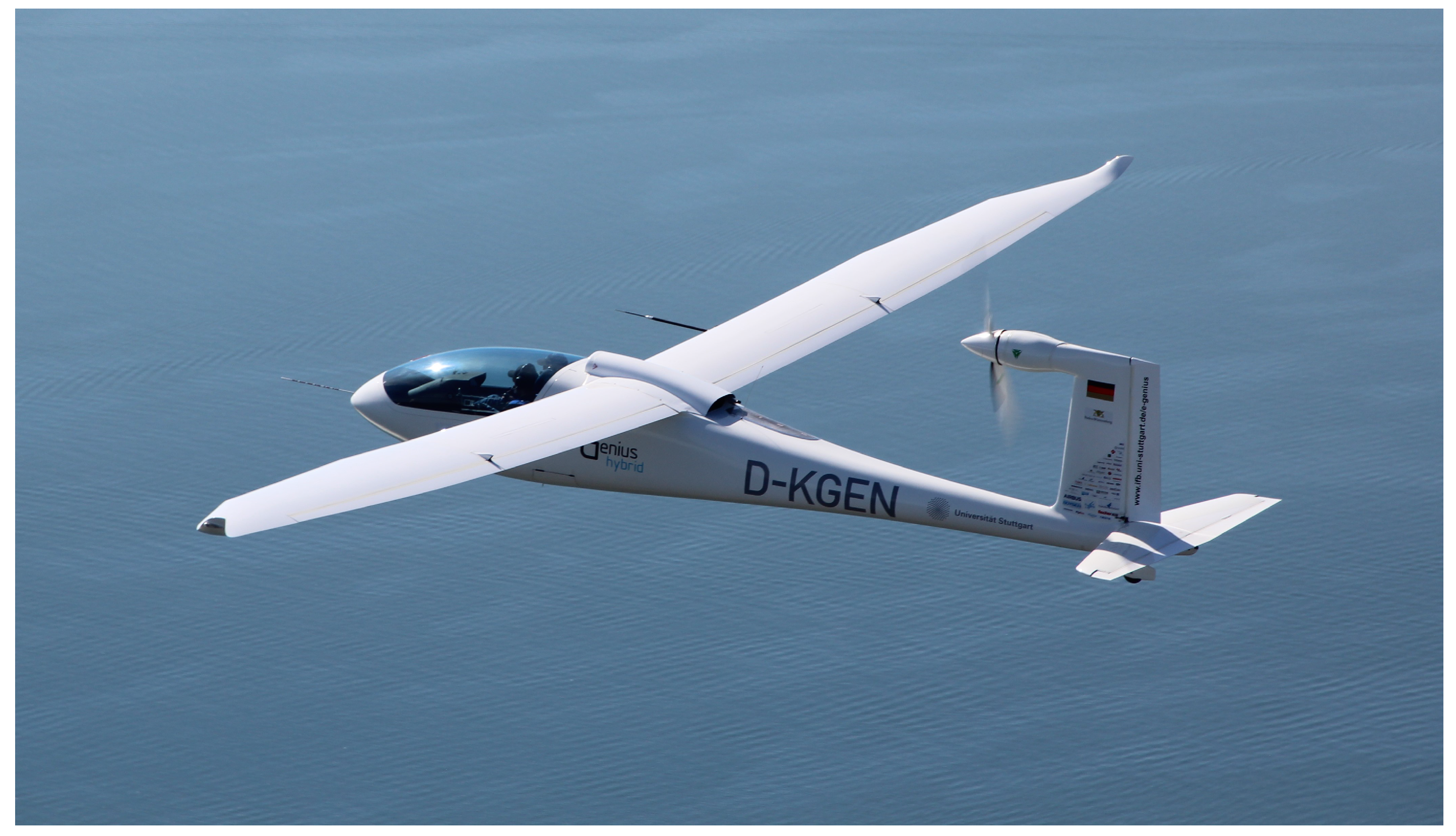
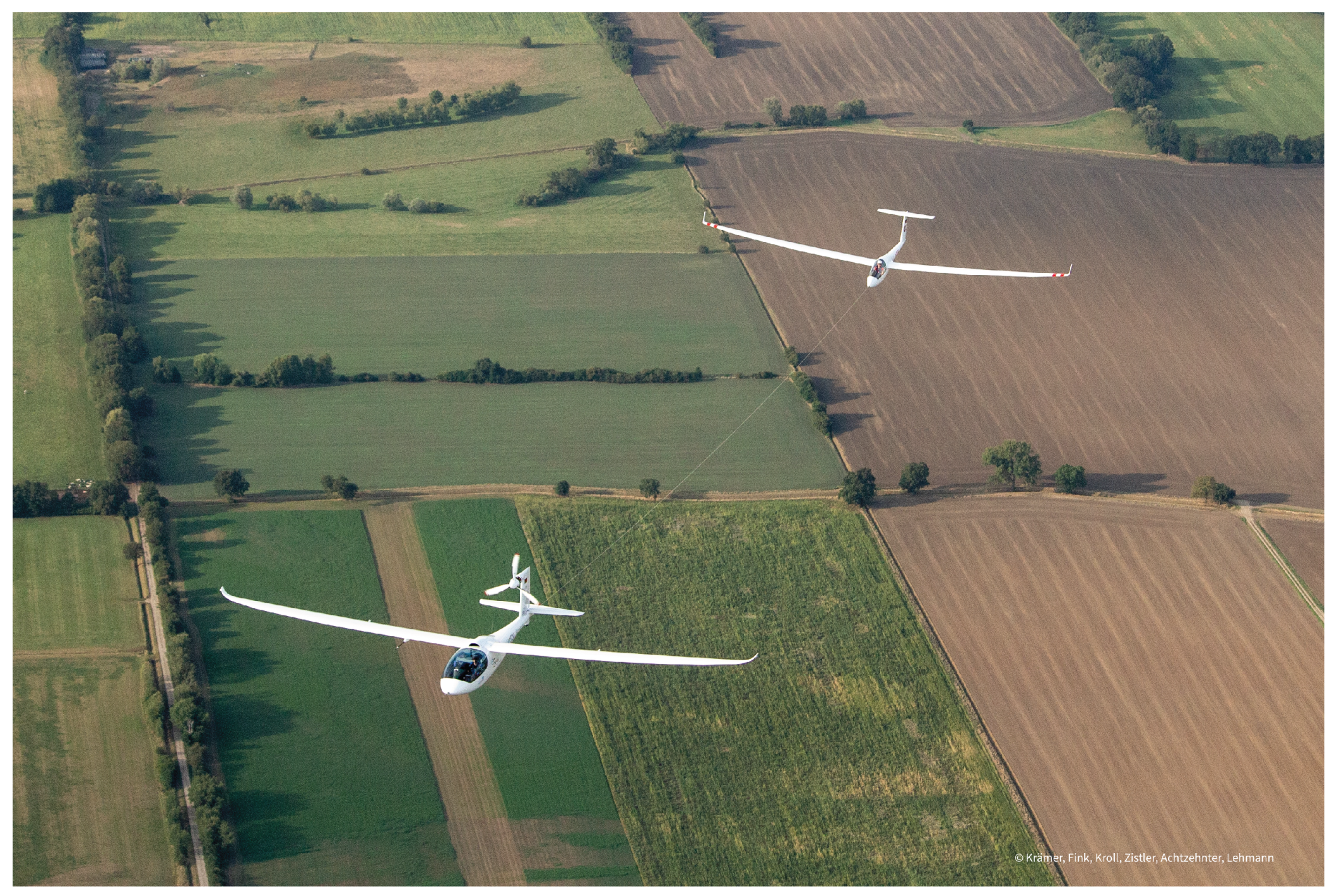
The advancements in electric propulsion, along with the benefits of high automation and intelligent flight guidance algorithms, have motivated the study presented in this article. The research was conducted as part of a project funded by the German Federal Ministry for Economic Affairs and Climate Action. The industry partners involved in the project include Air Energy Entwicklungs GmbH & Co. KG, based in Aachen, Germany, and Garrecht Avionik GmbH, located in Walldorf, Germany. To demonstrate the developed systems and to gather flight test data under real-world operating conditions, the electric research aircraft “e-Genius” from the University of Stuttgart was chosen as a flying testbed, performing electric aerotows using the described assistance and automation systems. First flown in 2011, the e-Genius is a TMG designed according to Joint Aviation Authorities (JAA) certification specifications for powered sailplanes [6], featuring an unconventional propeller integration at the top of the vertical stabilizer. Its carbon composite airframe includes a high aspect-ratio wing with full-span combined aileron and flaps (flaperons), a two-seat side-by-side cockpit, and ample space in the center fuselage for various energy storage systems. The aircraft is shown in flight in its high-performance hybrid (HPH) configuration, equipped with an internal compression ignition generator, in Figure 1. The underwing pod on the right wing, which contains a boom-mounted air-data-probe and associated electronics, and the dorsal cooling duct are clearly visible. The latter was originally installed during the conversion from battery to hybrid electric propulsion and is now reused in the current aerotow configuration, which is again purely battery-electric for reasons explained in Section 2.2.

Figure 1.
e-Genius in HPH configuration in 2022.
The remainder of this paper is organized as follows. Section 2 outlines the e-Genius setup, while Section 3 discusses the development of flight control algorithms for the e-Genius. Simulation results and flight test results are presented in Section 4 and Section 5, respectively. Section 6 concludes the paper and provides future perspectives.
2. Aircraft Setup
This section describes the modifications made to the e-Genius aircraft and the installation of new systems to prepare it for the later discussed flight test campaign.
2.1. Propulsion System
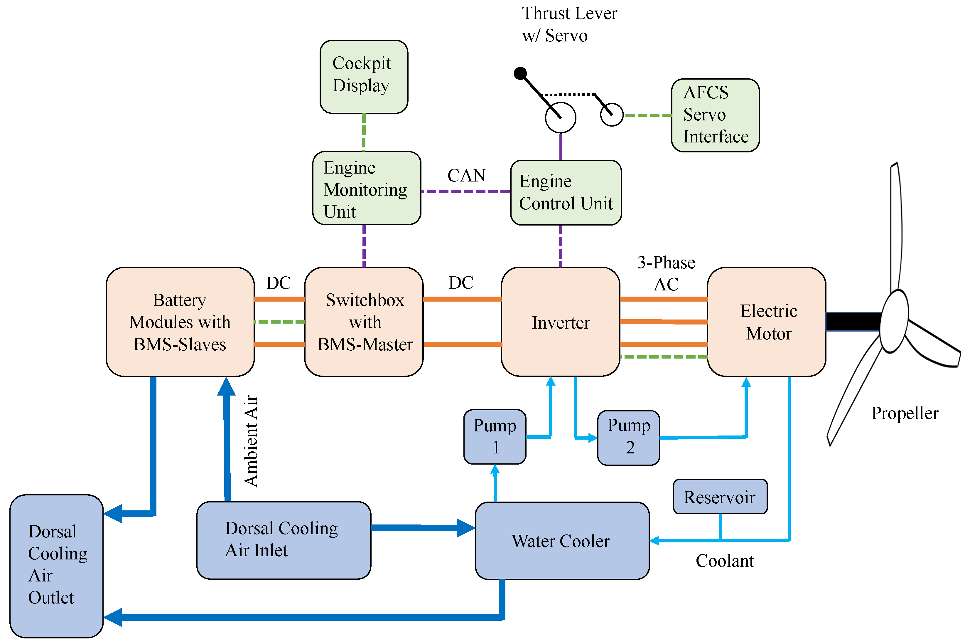
Modifications to the e-Genius propulsion system were necessary to achieve higher continuous power, which was previously limited by inadequate heat dissipation from the custom-made inrunner electric motor and a cooling system optimized for low-power cruise flight. The propulsion system architecture is shown in Figure 2. Herein, proprietary communication lines are represented in dashed light green, CAN-Lines in dashed purple and power lines are depicted in orange. The liquid cooling circuit is drawn in light blue and the cooling air flow in darker blue. Green boxes show control components, orange boxes are power components and blue boxes comprise the cooling system. Certain details, such as the battery charging inlet and the main fuse housing, are omitted as they are not relevant to the subsequent performance analysis.

Figure 2.
Simplified architecture of propulsion system, energy storage (battery), cooling system and relevant parts of the monitoring and control systems.
Specially, the electric motor and inverter are cooled via a liquid cooling circuit comprising two coolant pumps and an aluminum radiator. The pumps, a Pierburg CWA100 and a CWA150, are connected in series to increase the volume flow rate and provide basic system redundancy. All three main components of the powertrain, namely the propeller, electric motor, and inverter, were replaced with higher-power variants. The battery, which is not considered part of the propulsion system in this paper, is discussed separately in Section 2.2. One potential bottleneck in the system was identified in the AC-cables that connect the inverter to the electric motor located at the tail of the aircraft. Since the inverter is installed in the center fuselage, the cable length is approximately 6 m. These cables were installed during the original construction of the aircraft and could not be easily replaced during the conversion of the e-Genius. They have a cross-sectional area of 50 mm2 and use aluminum as the conductor material due to its superior mass-specific conductivity compared to traditional copper cables, thus reducing overall mass. These cables were sized for the aircraft’s primary cruise mission and not for prolonged high-power climbs. The estimated power losses in the cables and the resulting heat generation indicated limitations on achievable power and operating durations. Additionally, the cables were installed in a polymer tube along the fuselage wall, which restricts their heat dissipation. Temperature sensors were installed along the cables to monitor this potentially critical component.
The propeller was changed from a 2-bladed design to a 3-bladed configuration, with the blade characteristics otherwise remaining identical, using the same blade geometry but mounted on a different hub. It is an electrically actuated constant speed variable pitch (CSVP) propeller manufactured by MT-Propeller Entwicklung GmbH in Straubing, Germany. Table 1 compares the propeller used prior to the conversion with the new one installed for the aerotowing tests. The 3-bladed propeller allows for higher maximum power and can deliver the same power at a lower rotational speed, which is expected to reduce noise emissions and improve noise characteristics. A notable feature of the e-Genius is the relatively large diameter of its propeller, which contributes significantly to the aircraft’s overall propulsive efficiency [19].

Table 1.
Comparison of e-Genius propellers.
The electric motor originally installed in the e-Genius at its completion in 2011 has reliably powered the aircraft without any in-flight failures. It delivered sufficient power to meet the aircraft’s takeoff performance requirements and was proved efficient during cruise flight. However, the motor’s heat dissipation capabilities were inadequate, limiting the maximum continuous power available after the initial climb. Additionally, it has been surpassed in terms of power density by other available products. As a result, it was replaced with the serial-produced, off-the-shelf EMRAX 268 (EMRAX, Kamnik, Slovenia) in its medium-voltage and combined-cooled variant. This new motor has both a liquid cooling circuit and a perforated outrunning rotor, which facilitates heat dissipation via forced airflow through the motor. A comparison of the two motors that have flown on the e-Genius is provided in Table 2.
Table 2.
Comparison of e-Genius motors.
2.2. Energy Storage System
The energy storage system is reverted from the serial hybrid setup in the “high-performance hybrid” e-Genius variant (HPH) used in 2021 and 2022 to a purely battery-electric configuration. This change allows the internal combustion engine radiator to be repurposed to cool the electric motor and inverter, significantly increasing the cooling capacity of these components. The electric DC-power provided by the generator system ranges from 35 to 40 kWe, depending on ambient conditions. To achieve the required climb power of approximately 60 kWe, the remaining power would have had to be supplied by the 22 kWh batteries used in the hybrid setup. Aerotowing in general would be possible with this split power supply, however, additional cooling inlets and radiators would have been necessary to operate the diesel generator and the propulsion system at the necessary high power setting simultaneously. Additionally, in the specific case of the e-Genius, a weight reduction was necessary to allow for the AFCS components, mainly the servos, to be installed. The empty weight of the aircraft was reduced from 763 kg in the HPH-version (22 kWh battery plus generator) to 720 kg in the described version specialized for aerotow (40 kWh battery). This improves climb performance in general and lowers the wing loading which leads to a better matching of the best-climb airspeeds of e-Genius and the towed sailplane. For the aforementioned reasons and the added benefit of simplicity and complete lack of local carbon emissions, it was decided to use a battery-electric energy storage system.
To address this, Air Energy developed a new battery system, focusing on modularity to facilitate easy adaptation for similar small aircraft e-flight projects. The system consists of eight modules connected in series and a battery management system (BMS) slave circuit board. Each module contains 280 21700-format Li-Ion cylindrical cells of Samsung INR21700-50s type (Samsung SDI, Yongin-si, Republic of Korea). The cells within the modules are connected in a configuration of 20 in parallel and 14 in series. This results in a maximum voltage of 58.8 V at the terminals of each module, which remains below the 60 V threshold for high-voltage systems. The maximum voltage of the battery system is 470.4 V. The discharge cut-off is set as 3.0 V per cell, resulting in a system voltage of 336 V at cut-off. Each module has a nominal capacity of 5 kWh, leading to a total installed capacity of 40 kWh. The specified maximum current is 300 A, enabling a maximum power output of approximately 120 kWe, assuming a nominal voltage of 3.6 V per cell or 403.2 V for the whole system. The maximum continuous discharge current is specified as 200 A.
Each of the eight modules is hermetically sealed and equipped with an inlet and an outlet connection for a standard aircraft duct. Ram air from the main cooling inlet on top of the fuselage is directed into the modules for cooling. The air outlet of each module is collected into a manifold and expelled overboard at the aft side of the cooling duct. This design also ensures that any potentially toxic gases from battery cell outgassing are safely directed away from the crew compartment.
2.3. Automatic Flight Control System
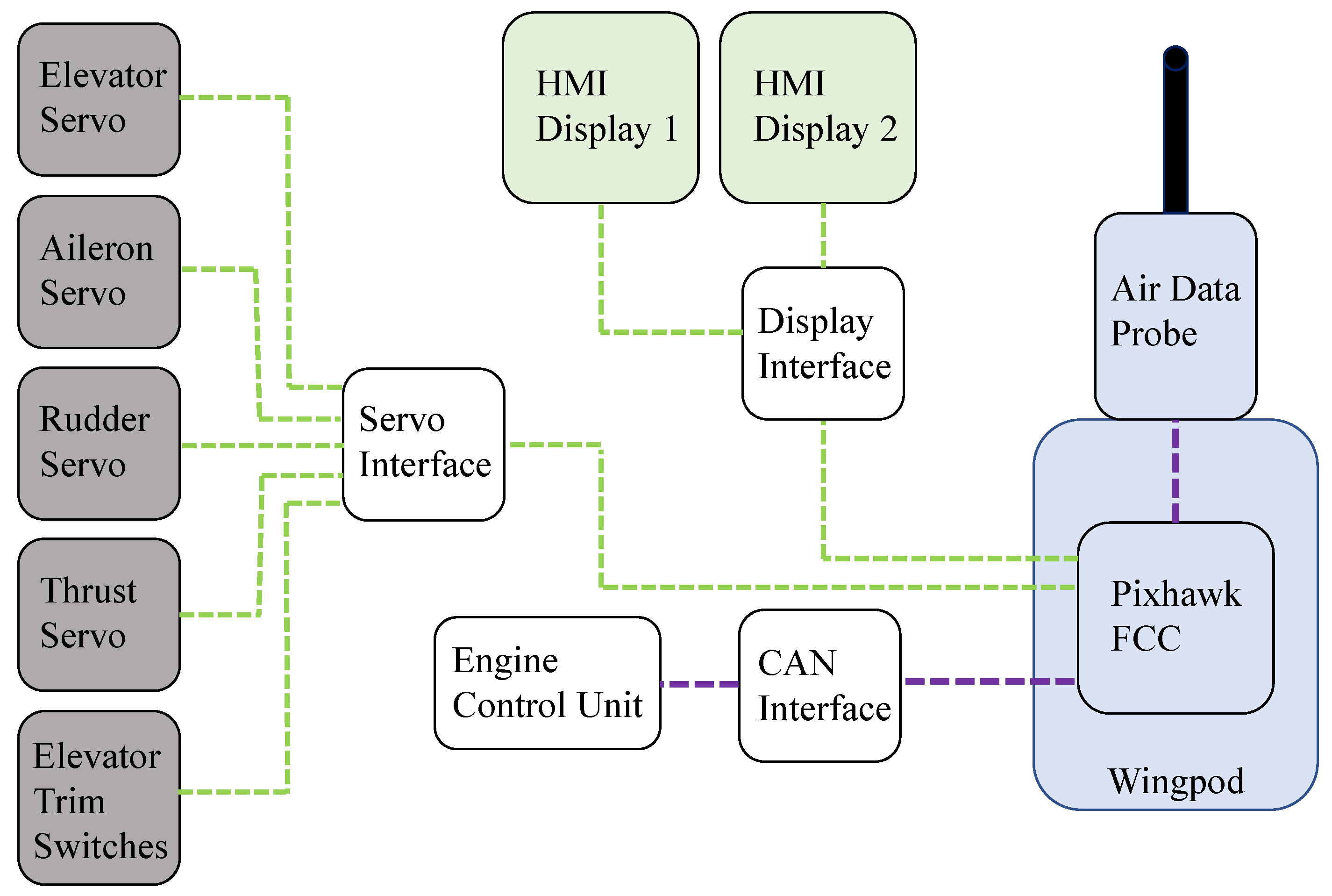
The AFCS consists of sensors, flight control computers, actuators, and human–machine interfaces (HMI), which collectively function to stabilize and control the aircraft. A simplified system architecture is given in Figure 3. Herein, CAN-lines are shown in dashed purple and other proprietary signal-lines in dashed green.

Figure 3.
Simplified architecture of the AFCS.
A Pixhawk 6X flight controller serves as the core of the AFCS. Pixhawk is widely used in unmanned aerial vehicles (UAVs) and experimental aircraft, but its feasibility for full-scale manned aviation faces challenges in regulatory compliance, hardware reliability, fail-safe mechanisms, and environmental resilience. It lacks certification under aviation standards like DO-178C and DO-254, and its single-board architecture lacks the redundancy required for safety-critical systems. Additionally, fail-safe features, cybersecurity protections, and compliance with DO-160G environmental standards are not inherently present. While unsuitable for certified aircraft without major modifications, Pixhawk remains viable for experimental aviation and scientific research.
The sensors integrated into the Pixhawk 6X, including inertial measurement units (IMU), barometers, and a magnetometer, along with a five-hole air data probe and a global positioning system (GPS) module, jointly provide the flight state data to the flight controller. The Pixhawk 6X, the air data probe, which is mounted on a carbon fiber boom, and the GPS module are housed in the underwing pod on the right wing of the aircraft.
For the primary actuators, Pegasus PA-R-340-9 (Pegasus Actuators, Wöllstadt, Germany) servos for optionally piloted vehicles were installed to control the elevator, ailerons, and rudder in accordance with commands from the AFCS. These servos feature both a switchable electromagnetic clutch and a slip clutch and were connected to the existing mechanical control linkages within the e-Genius fuselage at suitable locations. The AFCS can also control the power output of the propulsion system, enabling full autothrottle capability. This is achieved using a smaller Pegasus PA-R-205-4 servo, which physically moves the thrust lever in the cockpit, providing the pilot with an indication of AFCS actions and the current thrust setting. The manipulated variable is the motor current, which is proportional to the motor torque. The control variable is the DC power drawn from the battery, determined by the drawn battery current and DC voltage. These values are forwarded to the AFCS by the engine control unit so they can be used in the power control loop. The connection between the AFCS and propulsion system is purely mechanical via the linkage of the thrust lever and the thrust servo. This has the advantage of not relying on functioning software alone to ensure flight safety and the pilot can force the lever physically into the desired position by overpowering the servo at any time should the need arise. Additionally, the AFCS has access to a third control element: the elevator trim, implemented via a spring connected to the elevator control rod. This mechanism reduces long-term loads on the elevator actuator by trimming the aircraft to maintain the desired airspeed.
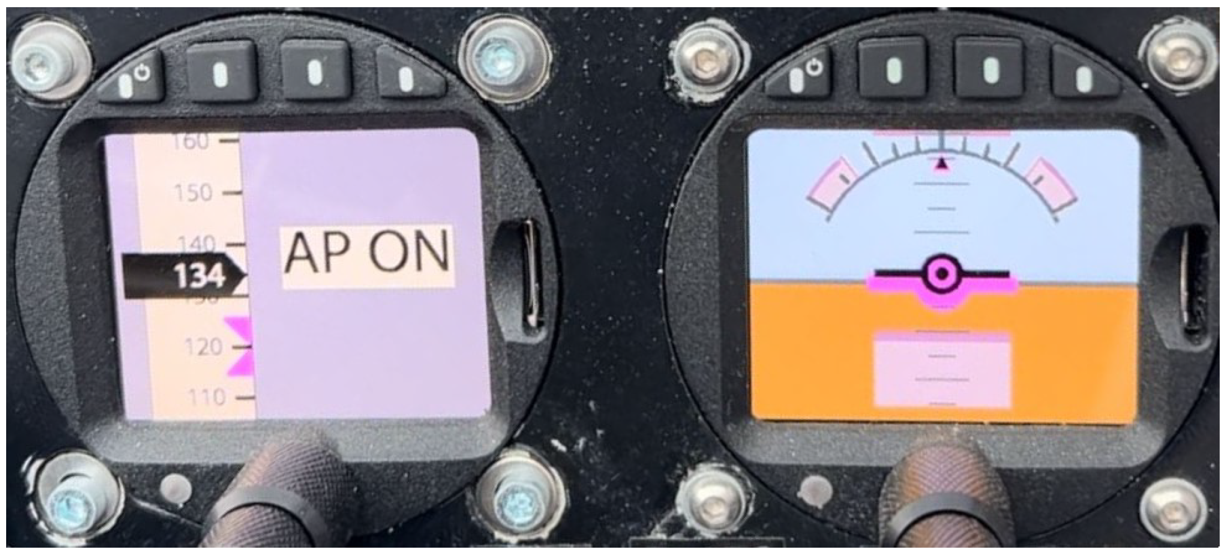
Two additional HMIs developed by Garrecht Avionik (Walldorf, Germany) were integrated into the instrument panel to facilitate interactions between the flight crew and the AFCS. As shown in Figure 4, the left one is a multi-function control display presenting an airspeed tape and a flight mode annunciator. The right one is an attitude control display showing an artificial horizon with an integrated flight director, where the current attitude is displayed in black while the AFCS-commanded attitude is in pink.

Figure 4.
HMI multi-function control display (left) and HMI attitude control display (right).
Once the AFCS is activated via the master switch, it displays the pitch and roll commands, as illustrated in Figure 4, enabling the aircraft to track the designed path. The pilot can manually follow these commands or engage the actuators via a separate switch for automatic control. Activating this switch powers the servos and their electromagnetic clutches, linking them to the flight control surfaces. Separating the activation of the AFCS and sensors from the actuator engagement allows the pilot to choose between manual and automatic control, facilitates a quicker transition back to automated mode after actuator deactivation, and may simplify future certification processes.
2.4. Towing Equipment
The additional towing equipment comprises the towing hook assembly and a rearward-facing camera. The towing cable is attached to a standard Tost E85 hook (Tost Flugzeuggerätebau, Munich, Germany), which is mounted on a bolt-on extension of the rear fuselage, known as the towing boom. This boom extends beyond the elevator to prevent the towing cable from interfering with or entangling the critical control surface. Additionally, a small camera is mounted on the towing boom, providing a rearward view that is transmitted to a cockpit display. This enables the pilot to monitor the towed sailplane, enhancing operational safety and ensuring compliance with the relevant certification specifications [6].
3. Flight Control Algorithm Development
This section outlines the process of developing flight control algorithms, followed by a detailed description of controller design.
3.1. Development Process
The development of flight control algorithms [22,23,24] follows a systematic process comprising the following key steps:
- (1)
- Plant modeling and system analysis
First, a high-fidelity nonlinear model incorporating the environment, aerodynamics, propulsion system, actuators, and motion equations is constructed. This model serves as the foundation for simulation and system performance evaluation. Then, for system analysis and controller design, a linear model is derived by trimming and linearizing the nonlinear model at selected operating points. Analyzing the linear model reveals the inherent dynamics and characteristics of the system.
- (2)
- Requirements definition
Prior to controller design, specific performance requirements are defined in both the time domain (e.g., overshoot, settling time, tracking error) and the frequency domain (e.g., gain margin and phase margin). These requirements establish design objectives for the control system.
- (3)
- Controller design and assessment
The controller design process involves selecting an appropriate control structure and tuning the control gains to meet the defined requirements. To evaluate the performance of the designed controller, model-in-the-loop (MIL) simulations are performed using both the linear and nonlinear models.
- (4)
- Deployment of flight control software
The deployment of flight control software refers to integrating the control software onto the target hardware. In this work, Pixhawk is employed as the flight controller, and all previous steps are executed in Matlab/Simulink (version 2020). Consequently, PX4 code is generated from the Matlab/Simulink implementation.
- (5)
- Validation, verification, and flight testing
Once the flight control software is deployed, processor-in-the-loop (PIL) simulations [24] are conducted, during which the controller model runs in real time on the processor, while the rest of the system remains in a simulated environment. This step identifies issues related to code generation and evaluates whether the processor is capable of executing the developed control logic. Subsequently, hardware-in-the-loop (HIL) simulations [25] are carried out. In this stage, the processor is connected to real hardware interfaces, while a high-fidelity real-time simulator emulates the aircraft dynamics. This step aims to validate the interactions between software and hardware, ensuring proper functionality under realistic conditions. Finally, flight tests are performed to assess the control behavior in real-world flight scenarios.
3.2. Controller Design
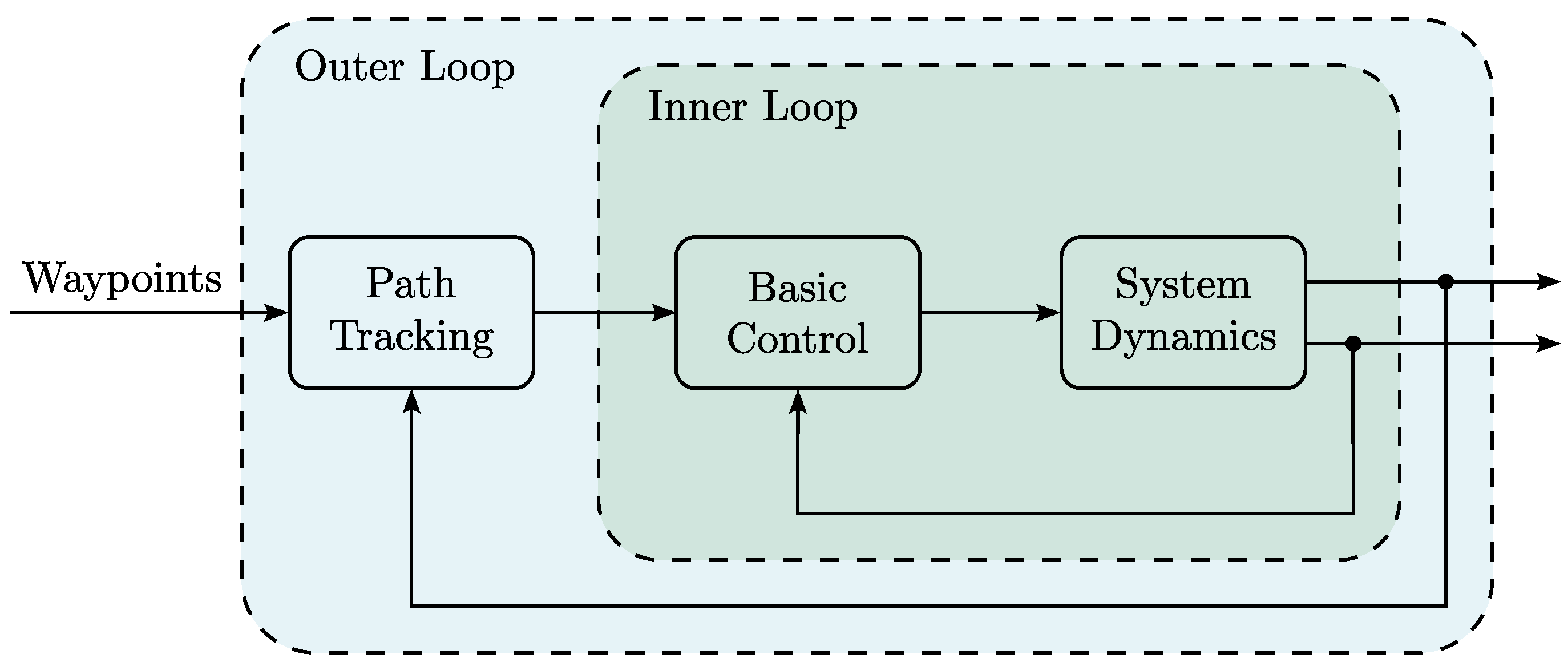
In this paper, the controller is structured into two loops: an inner loop responsible for basic control and an outer loop dedicated to path tracking [12], as illustrated in Figure 5. The inner loop ensures that the desired command inputs are achieved and sends commands to the actuators. The outer loop focuses on following the path defined by the given waypoints and provides commands to the inner loop. This controller is utilized in both conventional flight and aerotow scenarios.

Figure 5.
Control structure.
3.2.1. Basic Control
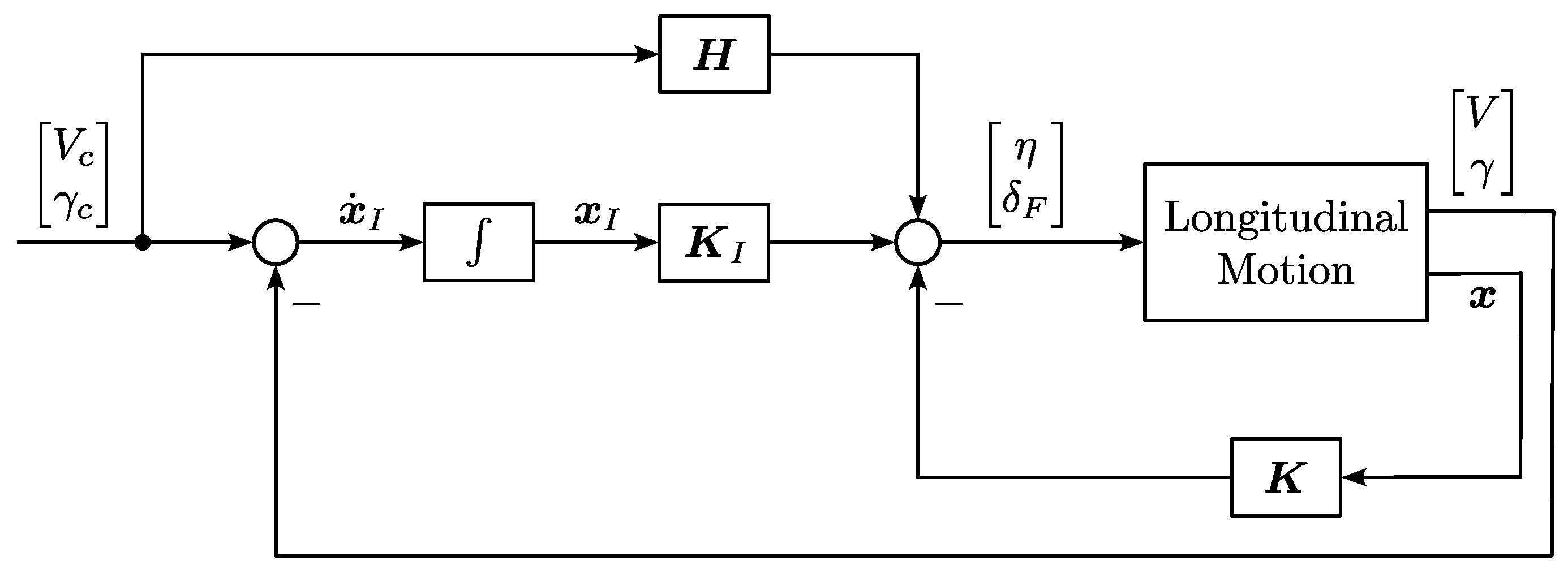
Figure 6 shows the basic control for the longitudinal motion [12]. The following 4th-order linear model of the longitudinal motion is used as the design model:
with the state and the input . Here, , q, V, , , and denote the angle of attack, pitch rate, airspeed, path inclination angle, elevator deflection, and thrust lever deflection, respectively. The subscript c represents “command”. State feedback control with integral and feedforward is employed, as described below:
where , , and represent the gain matrices for the state feedback, integral, and feedforward, respectively. It is an integrated design for both the short-period mode and phugoid mode. The state feedback improves system dynamics, the integrator eliminates steady-state error, and the feedforward term enhances tracking performance. Additionally, turn compensation is given by:

Figure 6.
Longitudinal control.
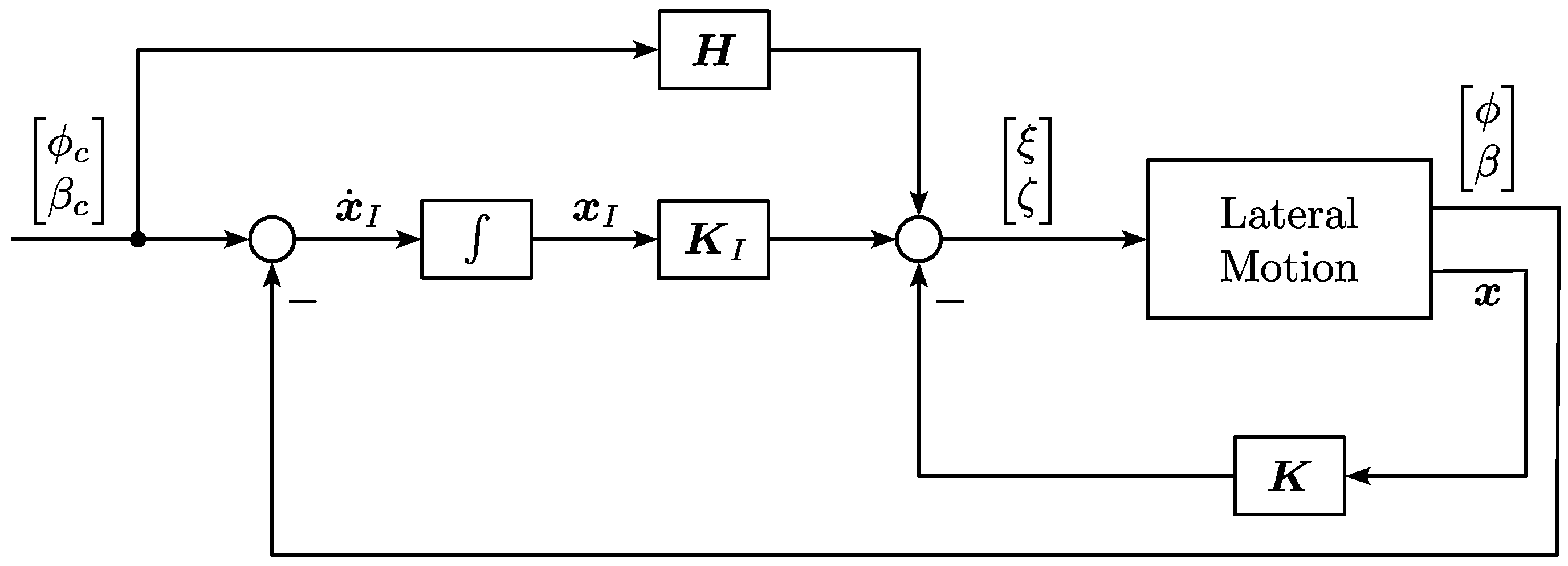
Similarly, the basic control for the lateral motion [12] is illustrated in Figure 7. The design model is also given by Equation (1), where the state is defined as and the input as . Here, r, , p, , , and denote the yaw rate, sideslip angle, roll rate, roll angle, aileron deflection, and rudder deflection, respectively. The control law is expressed as follows:
Zero sideslip flight can be achieved by setting .

Figure 7.
Lateral control.
Modal control [12] and eigenstructure assignment [26] are viable methods for designing the gain matrices by rearranging eigenvalues and eigenvector components. However, both methods rely on accurate system models. Inaccuracies in the models can lead to significant degradation in the controller’s performance when applied to high-fidelity simulations or real flight scenarios.
Instead, the gain matrices are tuned manually in the work. First, identify the components to be tuned. For example, if roll control is achieved by the aileron and yaw control by the rudder, only the corresponding gain components should be adjusted, while the others remain at zero. Next, set the integral and feedforward gains to zero, then gradually increase the feedback gains until the responses are sufficiently fast without excessive overshoots or high-frequency oscillations. Subsequently, introduce the integral gains incrementally and tune the feedback gains to minimize steady-state errors while ensuring system stability and limited overshoots. Finally, incorporate the feedforward gains and balance them with the integral gains to improve response speed while maintaining stability and acceptable overshoots.
3.2.2. Path Tracking
The path tracking in Figure 5 consists of three components: a path tracker, course control, and a waypoint switching algorithm.
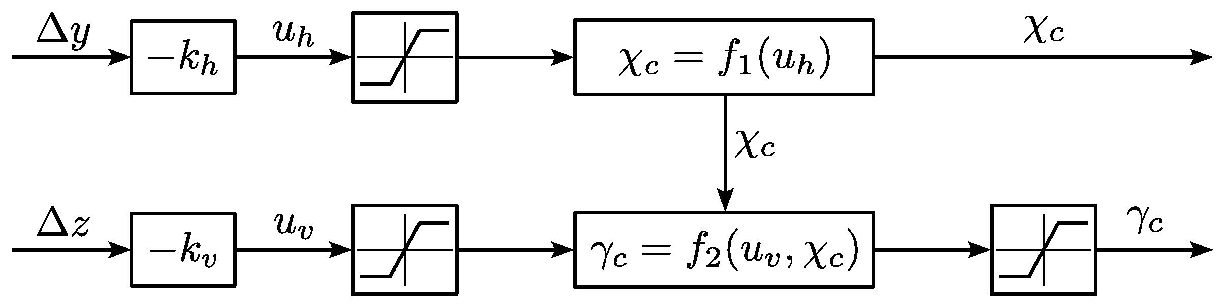
Figure 8 illustrates the path tracker [12]. Here, and are the aircraft’s position components along the y-axis and z-axis in the nominal path frame (see Appendix A). The controller derived from the motion equations using input–output linearization is given by:
with the following calculations for the desired course angle and the desired path inclination angle :
where and are the course angle and the path inclination angle defined by the nominal flight path (see Appendix A), and is the kinematic velocity. The limitations before these relations in Figure 8 are defined to ensure that the arguments of the arcsine functions remain within the range .

Figure 8.
Path tracker.
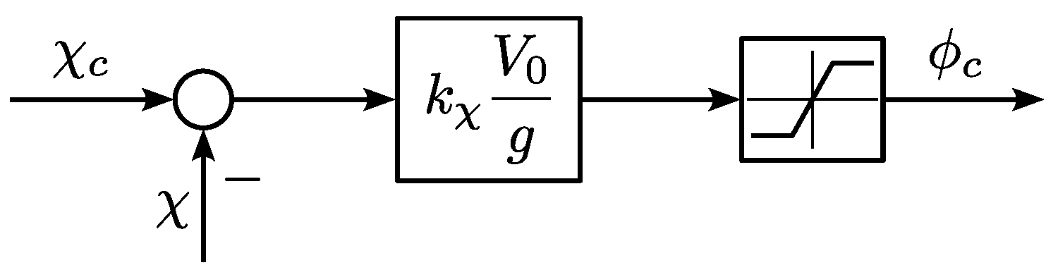
Figure 9 shows the course control, where is the airspeed at the operating point, and is the control gain to be tuned. The limiter for in Figure 9, as well as the limiter for in Figure 8, is designed to avoid excessive commands sent to the inner loop.

Figure 9.
Course control.
A simple waypoint switching algorithm is employed to calculate the switch distance, which determines when the target flight path should be switched to the next straight segment. Consider a stationary coordinated turn flight with a constant kinematic velocity and a constant roll angle , the turn radius R is calculated as
and the switch distance is given by
where denotes the angle between the current target path segment and the next segment.
4. AFCS Simulation Results
The simulation results for the closed-loop flight control system are presented in this section.
Consider the operating point to be a steady-state, straight, and level flight with and . The linear model at this trim point is given in Appendix B. The designed controller gains are listed in Appendix C.
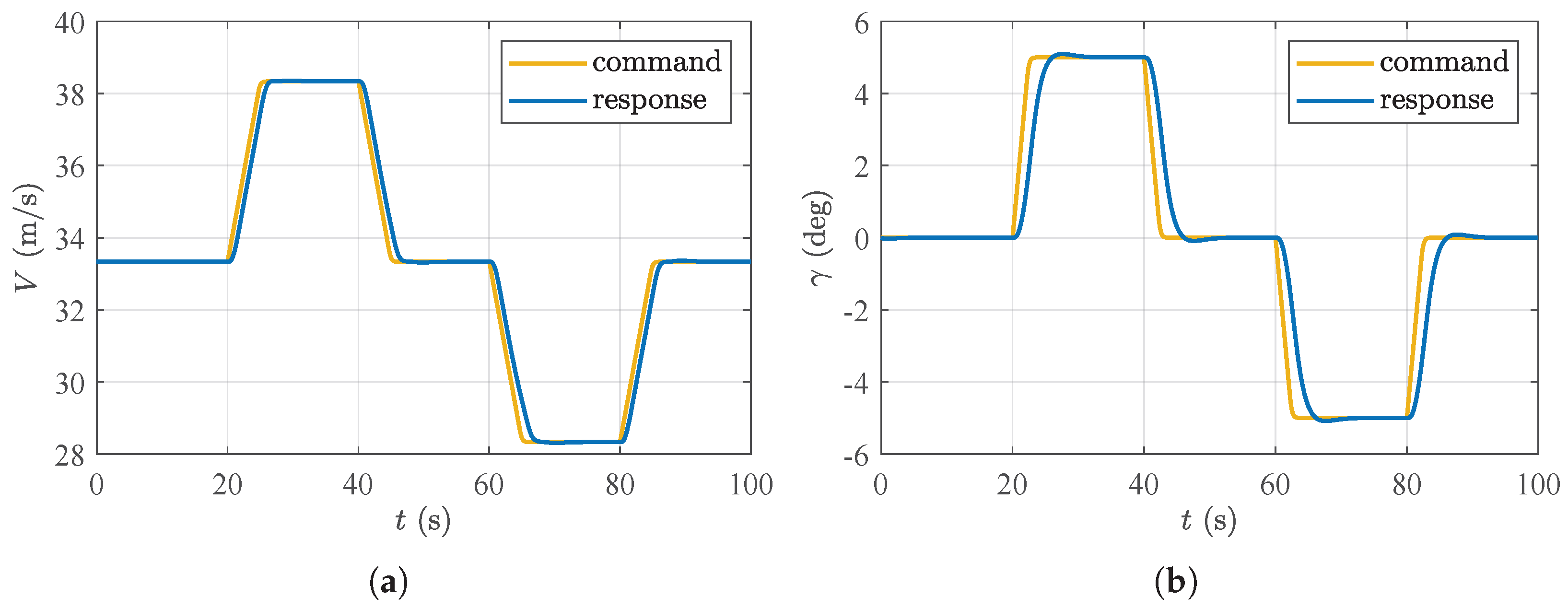
Figure 10 and Figure 11 illustrate the simulation results using the nonlinear model for longitudinal and lateral control, respectively. The original commands are step inputs applied at , , , and , with magnitudes of , , , and , respectively, in each subfigure. Note that when any one of these commands is applied, the remaining three are set to zero. The commands shown in the figures are the filtered versions of these step inputs, which limit the change rates of the command signals. The simulation results demonstrate that the closed-loop system is able to follow the commands quickly with sufficiently small overshoot, confirming the effectiveness of the designed controller.

Figure 10.
Simulation results for longitudinal control. (a) Airspeed tracking behavior; (b) path inclination angle tracking behavior.

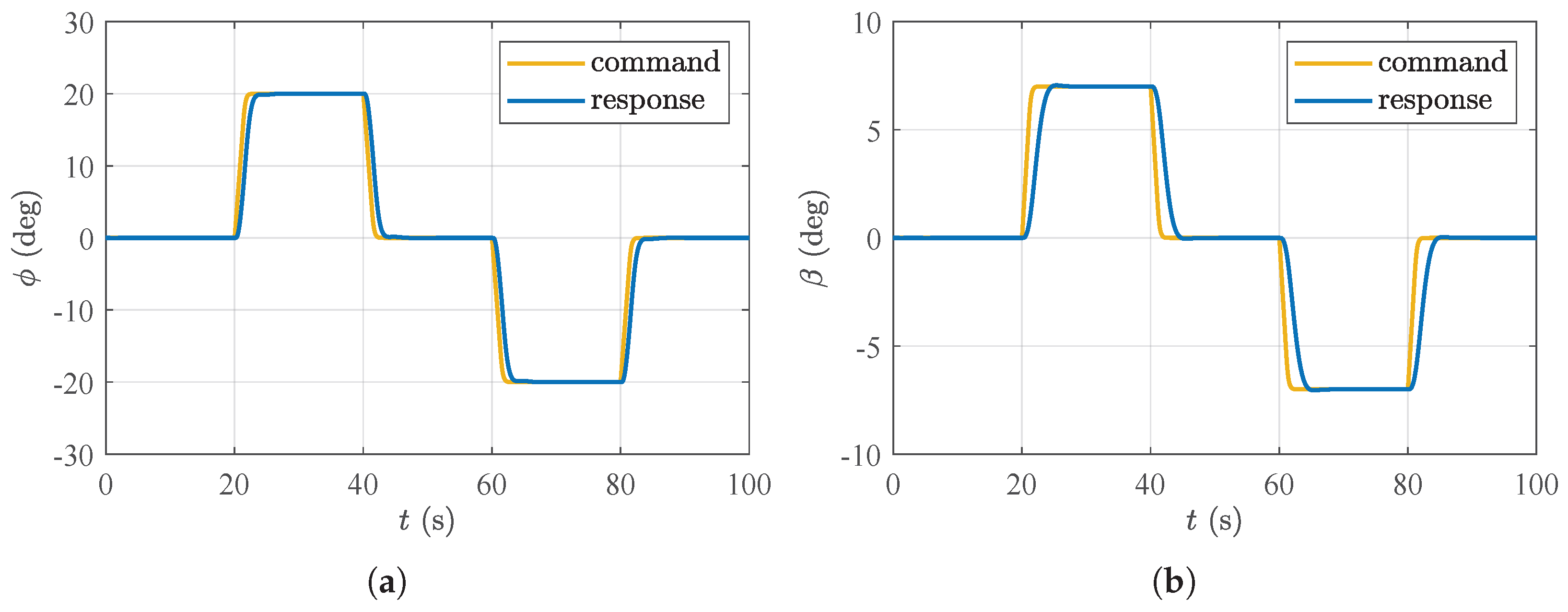
Figure 11.
Simulation results for lateral control. (a) Roll angle tracking behavior; (b) sideslip angle tracking behavior.
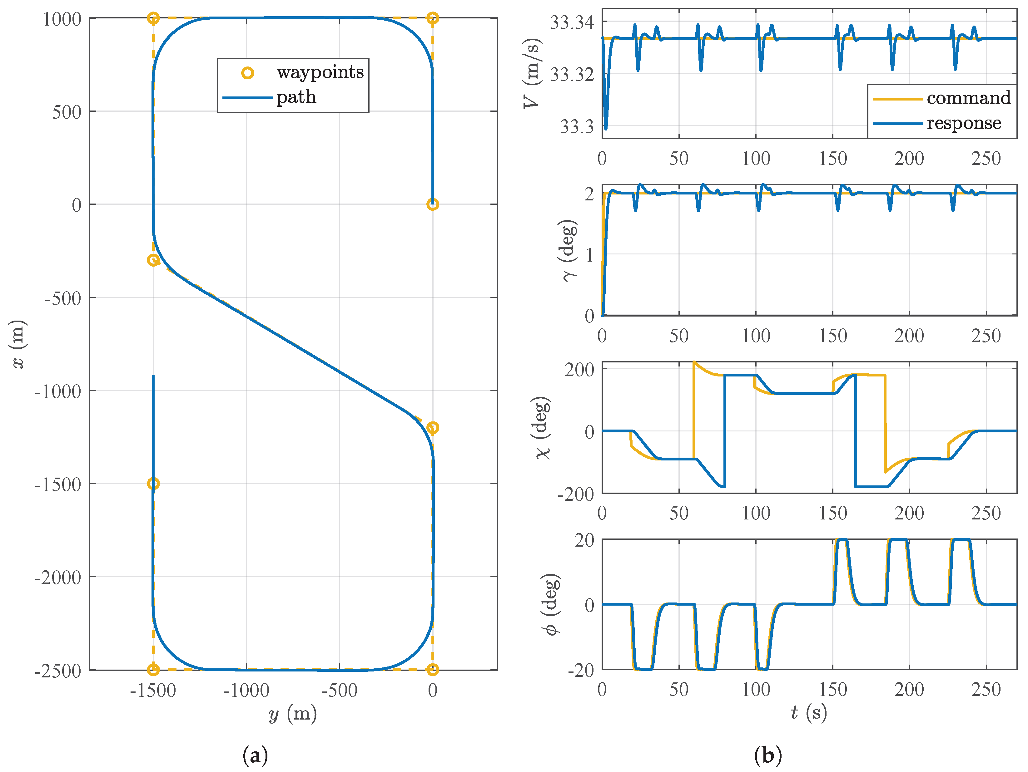
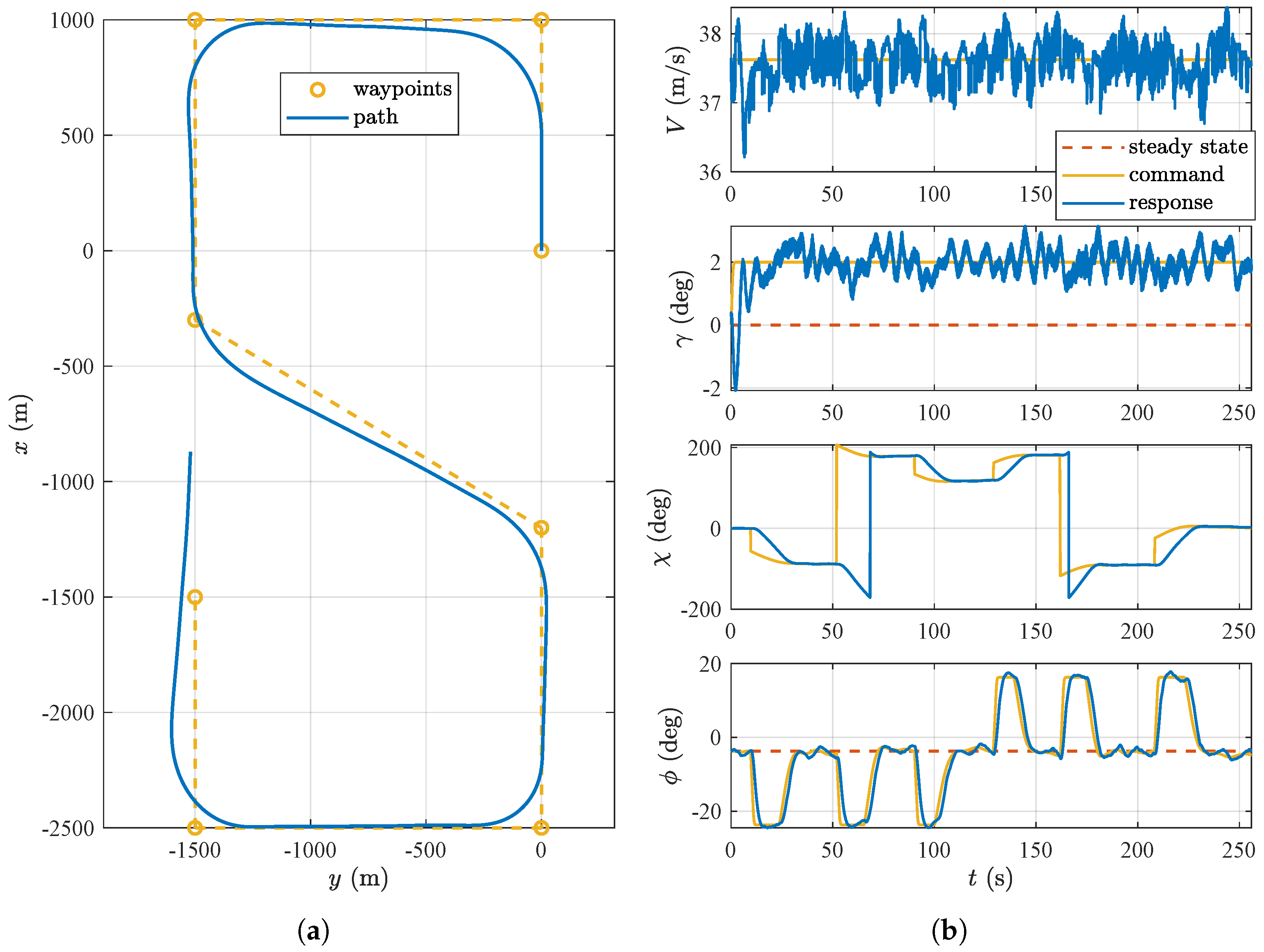
The simulation results for path tracking are presented in Figure 12. The simulation scenario is as follows: starting from the previously specified steady-state, straight, and level flight, the aircraft is tasked with maintaining a constant airspeed and following a series of two-dimensional waypoints in the forward-right-down (FRD) frame defined at the starting moment (see Appendix A), as shown in Figure 12a, with a prescribed path inclination angle . The roll angle is constrained to . As shown in the figures, the aircraft performs smooth turns and accurately tracks the target path, validating the capability of the designed controller. In addition, the inner-loop states closely follow the commanded inputs, further confirming the basic controller’s performance.

Figure 12.
Simulation results for path tracking. (a) Flight path; (b) basic control states.
5. Flight Test Results
This section presents the main results of the flight tests conducted between August and November 2024. It begins with the evaluation of the basic functions of the aircraft and its new propulsion system after conversion. The results of the aerotowing test campaign are then shown. Finally, the flight test results with the AFCS are presented. All altitudes presented in this section are given as height above ground level (AGL).
5.1. Climb Performance and Recuperation Tests
Preliminary to the actual towing tests, flights were conducted to evaluate the performance of the aircraft and its systems, most importantly the liquid cooling circuit and the forced battery ventilation. This gives an estimation of the available excess power that can be used for towing a sailplane of a certain weight and aerodynamic fineness. Table 3 lists the maximum operating temperatures for the components of the propulsions system and the battery cells. A critical objective of the climb performance tests was to qualitatively determine the thermal behavior of these components and to find the limiting component that determines the actual achievable continuous power.
Table 3.
Limit operating temperatures of propulsion components.
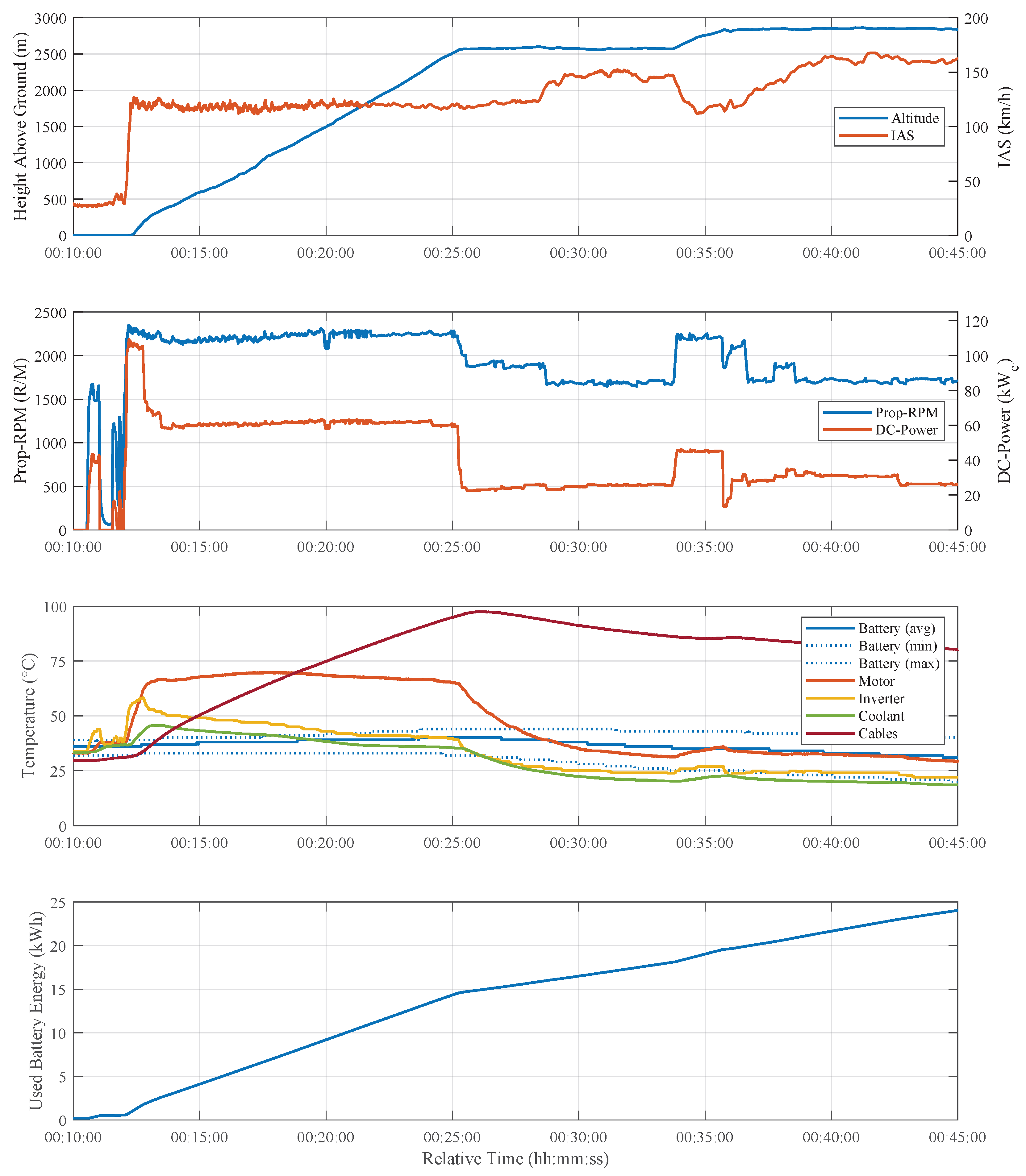
Figure 13 presents the data from a climb test flown on 6 August 2024 at 14:54 UTC and with a single pilot, corresponding to a takeoff mass of 820 kg. The climb is performed with a constant indicated airspeed of 120 km/h, which is the approximate speed for the best climb rate according to Schumann [19]. Takeoff power is set at 12:06 min relative time (00:00 min is the beginning of the data logging) and amounts to 107 kWe. Power is reduced at 12:45 min at an altitude of 173 m AGL. The average climb rate until this altitude is 6.4 m/s. This value compares to an initial climb rate of 6.65 m/s for the DR400 (900 kg), 8.4 m/s for the Bristell Classic (600 kg) and 7.0 m/s for the fs35 (850 kg) and represents ample excess power for aerotowing.

Figure 13.
Data from a climb performance test.
For the remainder of the climb, a constant power and propeller speed of 60 kWe and 2200 RPM are set, respectively. The climb is continued until a temperature limit is approached or an altitude of 2900 m is reached. The latter being the upper limit of the useable airspace without a clearance by air-traffic-control.
As can be seen in the Temperature graph, no temperature limit is approached during the takeoff and initial full-power climb phase. The initial state of the temperatures was ambient temperature, approximately 30 °C. After the reduction of power, the motor temperature reaches a plateau at approximately 70 °C while the inverter and coolant temperatures decrease again. The battery temperature changes rather slowly and increases by only 4 K until the interruption of the climb segment at 25:00 min. Contrary to the other components, the AC-cables that connect the inverter and the motor do not reach a steady state and get hotter continuously.
Eventually, the climb is arrested at 25:00 min and an altitude of 2580 m because the cable’s temperature limit of 105 °C is approached and a decent safety margin is advised in these early stages of flight testing. Power is reduced to 23 kWe and all temperatures can be observed decreasing. The cable temperature first has an overshoot of 2 °C within 60 s of the power reduction however, further indicating a still high rate of increase at the time of power reduction. The average rate of climb from 173 m to 2580 m can be determined to 3.23 m/s. After an eight minute cooldown cruise segment, the climb is completed to the target altitude of 2900 m. All components except the AC-cables are cooling down significantly in this period, the ambient temperature at altitude being approximately 10 °C. The AC-cables show a longer time constant than the rest of the components with the exception of the battery but can be cooled down enough to continue the climb.
The lowest subplot of the figure shows the consumed battery energy over time. Since the takeoff at 12:10 min relative time, 24 kWh of the battery energy have been used at 45.00 min. This corresponds to 60% of the total installed capacity used for 32:50 min of flight time and an altitude increase of 2900 m.
Although true continuous operation was not achieved at the desired climb power of 60 kWe, the test demonstrated sufficient climb performance and available operating time to conduct aerotows, the reachable altitude being limited by the temperature of the AC-cables.
Another feature of the new system to be tested was the regenerative braking function of the inverter, also known as recuperation. In this operation mode, the electric motor operates as a generator with the propeller acting as a wind turbine, extracting energy from the incident airflow and supplying a torque to the motor/generator. The resulting AC-current is stepped up and rectified by the inverter to a DC-Voltage that is above the current battery voltage, which results in an effective charging current to the battery. This feature has been tested in electric aircraft before [27] and can harvest some of the energy during a steep descend, which is otherwise dissipated through drag increasing devices by conventionally powered aircraft.
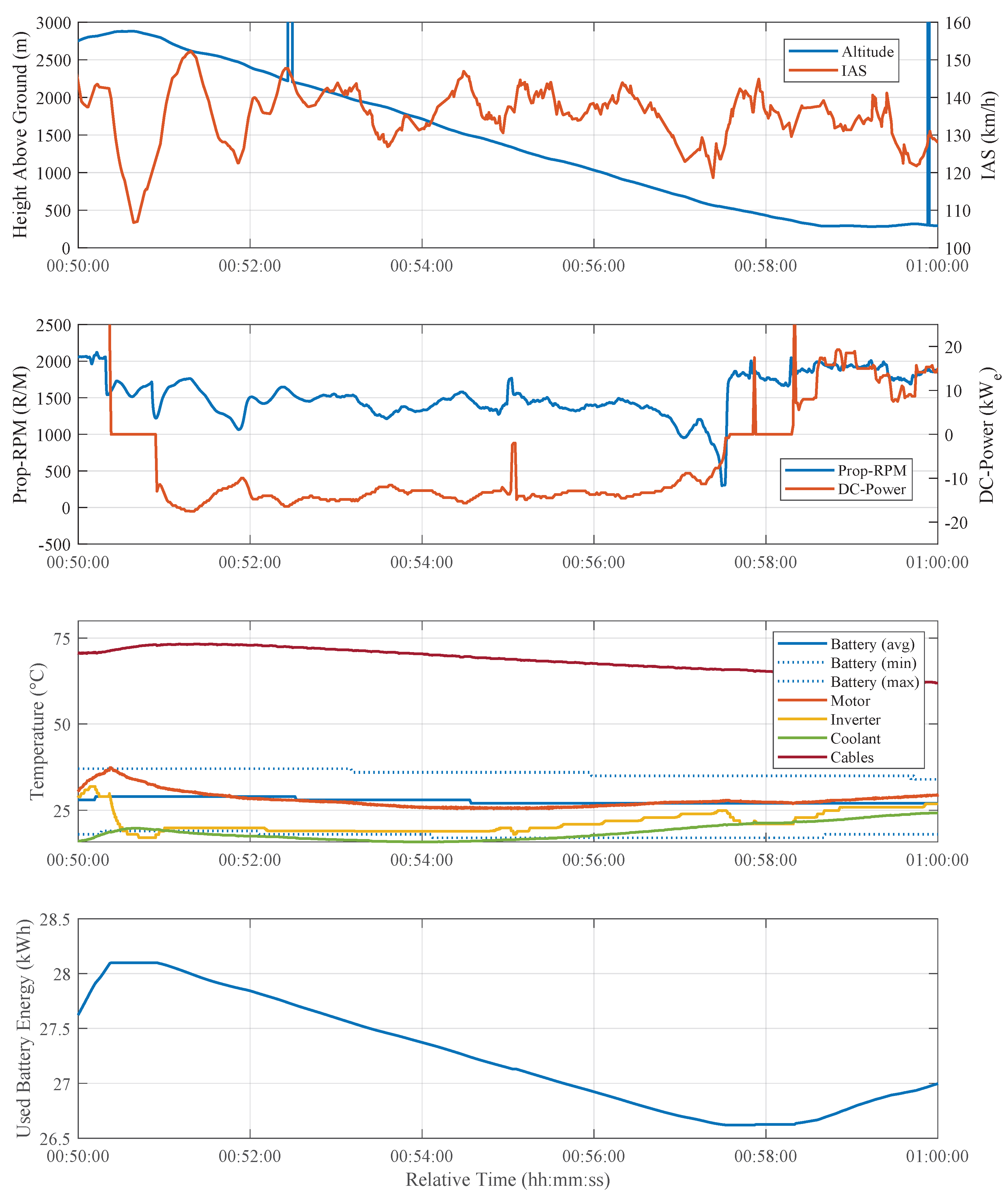
Figure 14 shows data captured during a steep descent with the use of regenerative braking. The evaluated altitude step begins at 2900 m and ends at 600 m AGL. The airspeed is approximately constant at 140 km/h IAS. The DC-power can been seen going negative at 50:53 min relative time, indicating a power flow to the battery. The propeller controller is set to 2300 RPM which leads to the pitch going to the lowest possible setting. The rotational speed settles at approximately 1500 RPM. At around 57:10 min, the rotational speed begins to rapidly decrease after a slight drop in airspeed from 142 to 124 km/h IAS. This might be indicative of a stall on the propeller blades which leads to a sudden increase in drag and, together with the braking moment of the electrical machine, slows the propeller down rapidly. This was realized during the flight and the test was aborted at this point due to the unknown behavior of the system.

Figure 14.
Recuperation test data.
The temperatures are not critical during this test. It can be observed that the AC-cables do not heat up from the power flow during regenerative braking and the temperature keeps decreasing instead which would have also been the case if a positive power of 15 kWe had been set.
Of interest for this test is the graph of the consumed battery energy. It can be seen decreasing during the period of negative DC-power. The total energy that was directed back to the battery is measured as 1.48 kWh. However, this is not the energy that is stored in the battery for later use as some of it is lost as heat and the charging efficiency of the cells has to be taken into account. If this is not considered and only the electric energy that is supplied to the DC-side of the inverter is evaluated, one can define a recuperation efficiency as the ratio of the potential energy stored by the aircraft in its altitude to the converted to electrical energy:
with the mass of the aircraft , the change in altitude , the gravitational constant g and the accumulated electrical energy . Using an altitude difference of 2300 m, an aircraft mass of 880 kg, and converting the electrical energy from kilowatt-hours to Joules, one obtains a value of:
Considering that the propeller blade geometry is not optimized for operation as a wind turbine, whereby the propeller blade airfoil is creating lift with a negative coefficient with respect to it’s camber, this value is not significantly lower as the one obtained in [27]. Their study presents flight test results for recuperation tests done with an optimized propeller geometry. The value obtained there is 32.8%, with the Pipistrel Alpha Electro aircraft used for the tests assumed to have flown at its maximum takeoff mass of 550 kg.
The results of the recuperation tests and the availability of e-Genius as a flight test platform capable of recuperation can now be used for future more detailed research to close gaps identified in this field, for instance by Mayntz et al. [28]. This study aims to set up a Stemme S10 TMG with wingpods containing propellers connected to electric machines for flight tests with a focus on recuperation behavior.
Recuperation is especially useful for aerotowing and similar flight missions like the dropping of skydivers, because the aircraft does not have to cover any distance after releasing or dropping its payload and has to descend to and land at the departure airport which is usually directly below it. Electric propulsion offers the capability of energy harvesting on the descend, a feature not available to any other form of established aircraft propulsion.
However, effects on the state of health of the battery are still subject to further research. Recuperation during flight effectively acts as additional charging cycles on the cells, although the depth of the cycle is small compared to a regular full charge. Recuperation can only be performed at an SOC of less than 80% due to otherwise exceeding the maximum allowable voltage of the battery system. Constant voltage charging is not feasible for use during in-flight recuperation due to the small charge rates. Concerning the discharge rate of an individual cell, the predominant DC-Power of 60 kW corresponds to a discharge rate of 1.5 C per cell, which is well below the cell manufacturers’ specification of 5 C for a cycle life of 250 cycles with 60% of rated capacity remaining.
5.2. Aerotow Without AFCS
After it had been established by the aforementioned flight tests that enough excess power and operating time was available to safely tow a sailplane with e-Genius, this was first done on 19 August 2024. The airfield used was Stendal–Borstel, ICAO-code EDOV. This airport features a low field elevation and thus density altitude and a 2000 m concrete runway without substantial obstacles in the vicinity. The sailplane type chosen for the first aerotow was a Schempp–Hirth Discus CS. It features a glide ratio of 1:43 and a relatively low empty mass of approximately 280 kg when not ballasted with water, both factors contributing to a limited negative effect on the climb performance of the aerotow. Furthermore the wide-spread type has simple handling characteristics and had been flown before by the sailplane pilot conducting the first aerotow. The e-Genius can be seen towing a Discus CS on the fourth conducted aerotow in Figure 15.

Figure 15.
e-Genius electric aircraft towing a Discus CS sailplane.
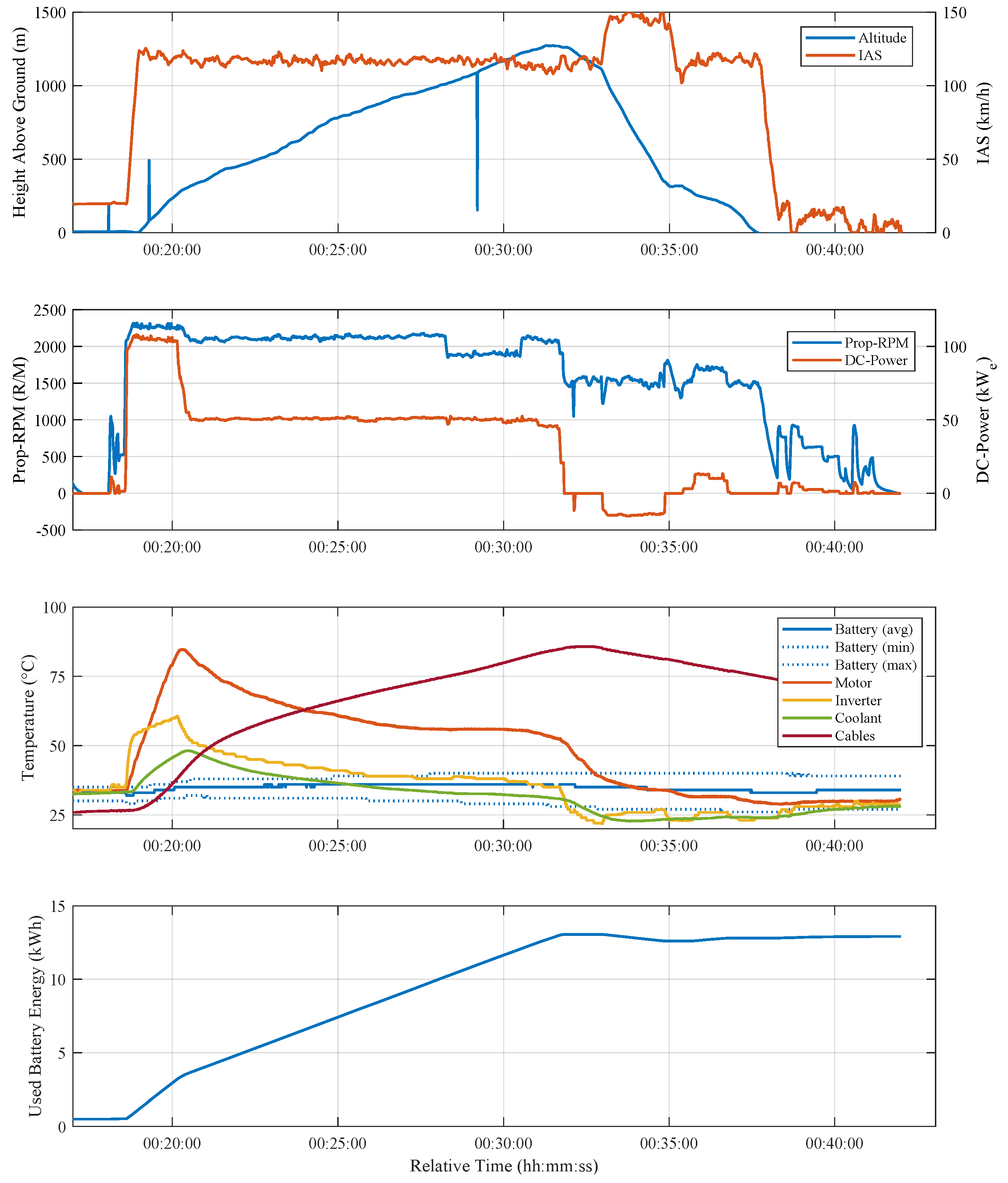
Figure 16 shows the data captured during the first aerotow performed by the e-Genius. Full power was set for takeoff and kept for approximately 90 s. At that point an altitude of 260 m had been reached with an average climb rate of 3.94 m/s with actual lift-off occurring approximately 24 s after takeoff power was set. The climb was further conducted with 50 kWe to have more time until the temperature limit of the AC-cables was reached. Despite the reduced power, climb rate was still ample and the sailplane was released at an altitude of 1267 m after 12:23 min of elapsed flight time, resulting in an overall average climb rate of 1.71 m/s.

Figure 16.
Data from the first aerotow with a 360 kg Discus CS.
The temperatures proceed as expected, with the motor and inverter heating up relatively quickly but not limiting the available duration of takeoff-power to an unsafe value. The requirement there being to reach a safety altitude of 150 m before having to reduce power. The AC-cable temperature does not rise as fast due to the reduced power setting and reaches a maximum of 86 °C at the release point, so the continuation of the climb would have been possible but was omitted to directly conduct a subsequent flight.
On the descent, the recuperation capability could also be demonstrated, as can be seen by the negative DC-power from 33:00 to 34:50 min elapsed time. An energy of 0.46 kWh was recuperated and routed back to the battery. The towing efficiency can be defined as the ratio of the energy that has been transferred to the sailplane and the applied electric energy:
with the applied electric energy , the mass of the sailplane and the release altitude above ground . For the sailplanes’ energy, its kinetic energy is neglected, as is it much smaller than its potential energy. This is especially true for high release altitudes.
For the presented flight, with an applied electric energy at release of the sailplane of 13.05 kWh, a sailplane mass of 360 kg and a release altitude of 1267 m, the towing efficiency calculates to:
Also considering the kinetic energy of the sailplane would further increase this value slightly. Another way to visualize the energy efficiency of the electric towplane is the comparison of the applied electric energy to the equivalent amount of regular aviation gasoline (AVGAS) that contains the same caloric energy. Given a caloric value of 43.5 MJ/kg [29] and a density of 0.75 kg/L, an electric energy of 13.05 kWh would be equivalent to the energy content of 1.08 kg or 1.44 L of AVGAS.
To compare the energy efficiency of e-Genius to contemporary towplanes such as the Bristell classic 915, the fs35 and the DR400-180R mentioned in the introduction, the towing efficiency for an aircraft with a combustion engine is again considered as the ratio between the useful energy (the potential energy of the sailplane after launch) and the deployed energy now in the form of the chemical energy bound in the gasoline or diesel fuel used instead of electricity:
with the fuel flow in kg/s, the vertical velocity in m/s and the heat of combustion in J/kg.
For the DR400-180R, with a fuel flow at maximum continuous power of approx. 50 L/h and a typical climb rate of 2.5 m/s with a 550 kg sailplane (double seated Schleicher ASK 21), the towing efficiency is:
This value would represent a conventional airframe of wooden construction paired with a relatively inefficient naturally aspirated, direct drive and high-displacement aero engine of older design, namely the Lycoming O-360. If the Bristell Classic 915 is considered next as an example of a modern airframe of similar basic design as the DR400 (low aspect ratio wing, optimized for cruise) combined with a modern turbocharged gasoline engine of more recent design and fuel injection (Rotax 915 iS), its towing efficiency is:
The next step in optimizing a towplane was done by the Akaflieg Stuttgart in combining an airframe designed for high climb rates at the same airspeed as the towed glider with an efficient turbocharged diesel aero engine (Continental CD-155). This can also be seen if the towing efficiency of the fs35 is calculated using a fuel flow of 30 L/h and a climb rate of 3.5 m/s when towing the 550 kg ASK 21:
Table A3 in Appendix D gives an overview of all conducted aerotow test flights with e-Genius. It can be seen that the towing efficiency is generally better for higher sailplane masses and for higher average climb rates. However, it has to be kept in mind that the influence of atmospheric updrafts is hereby included in the data as some flights were conducted during daytimes with active thermals. This would, however, be also true for all other towplanes. Further main influences on the exact value of the energy efficiency of a sailplane launch by aerotow are the type of sailplane and its aerodynamic characteristics, its wing-loading, the density altitude and the chosen power setting of the combustion engine or electric motor in combination with the setting of the CSVP Propeller.
Even the lowest obtained towing efficiency with a value of 7.6% still represents a 13% increase when compared to the most efficient considered conventional towplane, the fs35. The average towing efficiency of e-Genius during the flight test campaign was 11.2%, representing a 67% increase in energy efficiency over the fs 35 and even a 361% increase over the DR400.
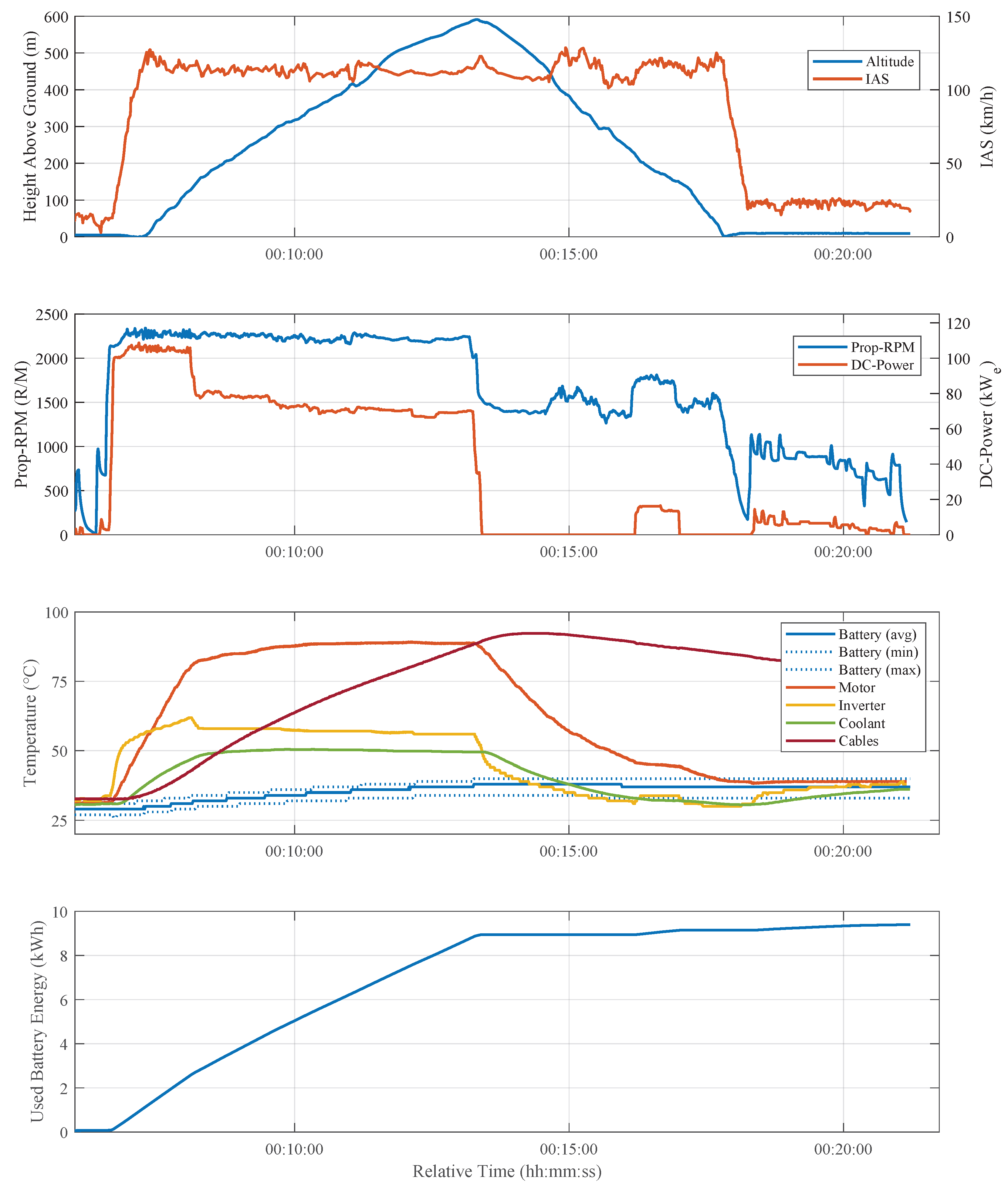
Figure 17 shows the data that was captured while towing the highest takeoff mass (TOM) sailplane of the campaign, a Schmepp–Hirth Arcus S ballasted with water to reach a TOM of 750 kg. Climb power had to be set at approximately 70 kWe to maintain an acceptable climb rate. This lead to the quick increase of AC-cable temperature, which limited the attained altitude to 600 m AGL. However, it can be seen from the temperature plot that all other components were still far enough below their limits to continue the climb. The motor, inverter and coolant reach an equilibrium and the battery heats up at a slow enough rate to either enter equilibrium or not reach the limit temperature before its contained energy is depleted, thus not being the limiting factor for attainable altitude.

Figure 17.
Data from towing the 750 kg Arcus S.
The towing efficiency on this flight was 13.3% and the equivalent amount of AVGAS used until sailplane release is 0.74 kg or 0.99 L.
5.3. AFCS
Due to model inaccuracies, the controller gains are further tuned based on the results in Appendix C during real flight. The flight test results are presented below.
The test scenarios are similar to those in Section 4. We assume that the aircraft is in a steady-state, straight, and level flight before activating the AFCS. Under this assumption, some steady states are known, such as . The steady values of V, , and are considered to be the corresponding state measurements at the moment the AFCS is activated. Although the actual steady-state values of and should be zero, the measured values of and are biased because of installation errors.
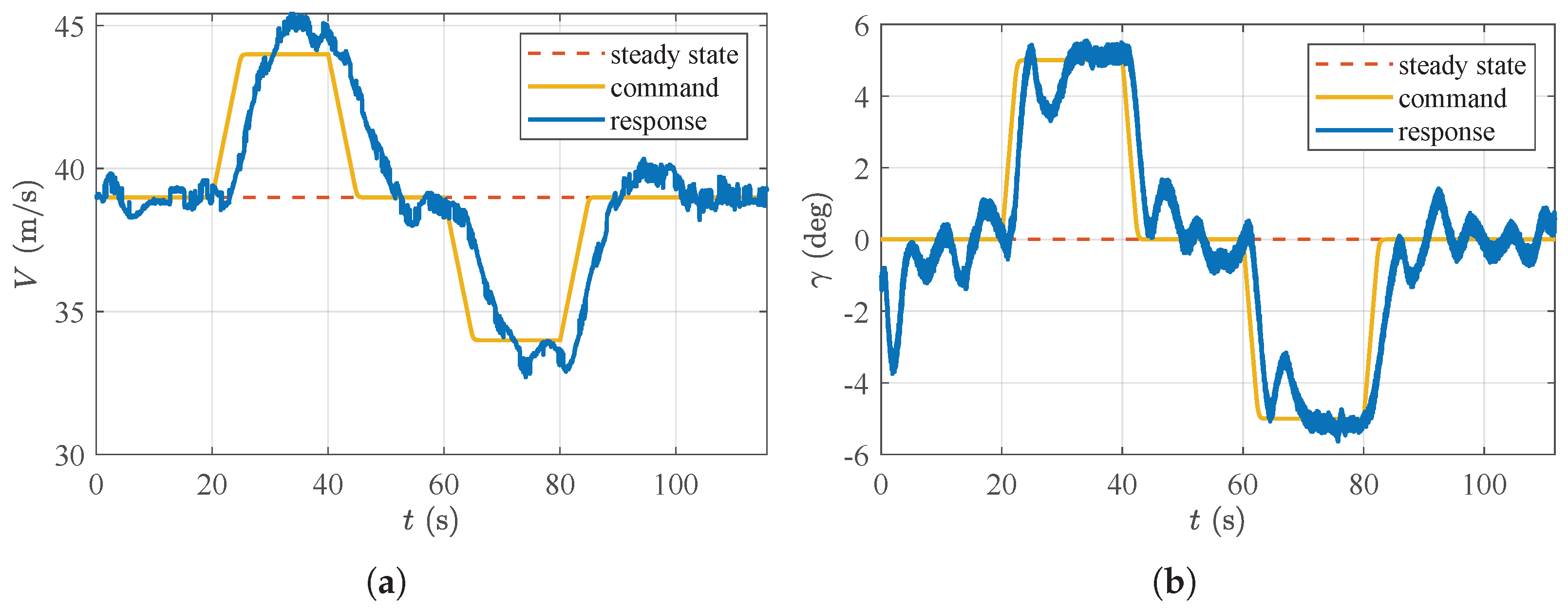
Figure 18 and Figure 19 show the flight test results for longitudinal and lateral control, respectively. As before, the tracking behaviors are evaluated separately, and the commands in the figures are the filtered versions of the step inputs applied at , , , and . The results indicate that the implemented controllers are able to track the desired command inputs within a few seconds. The presence of measurement errors, external disturbances (such as wind and temperature variations), and complex system nonlinearities (including delays and deadbands) poses challenges to stability. However, the system’s responses remain close to the commands, with some oscillations observed, indicating that the controller demonstrates a certain degree of robustness.

Figure 18.
Flight test results for longitudinal control. (a) Airspeed tracking behavior; (b) path inclination angle tracking behavior.

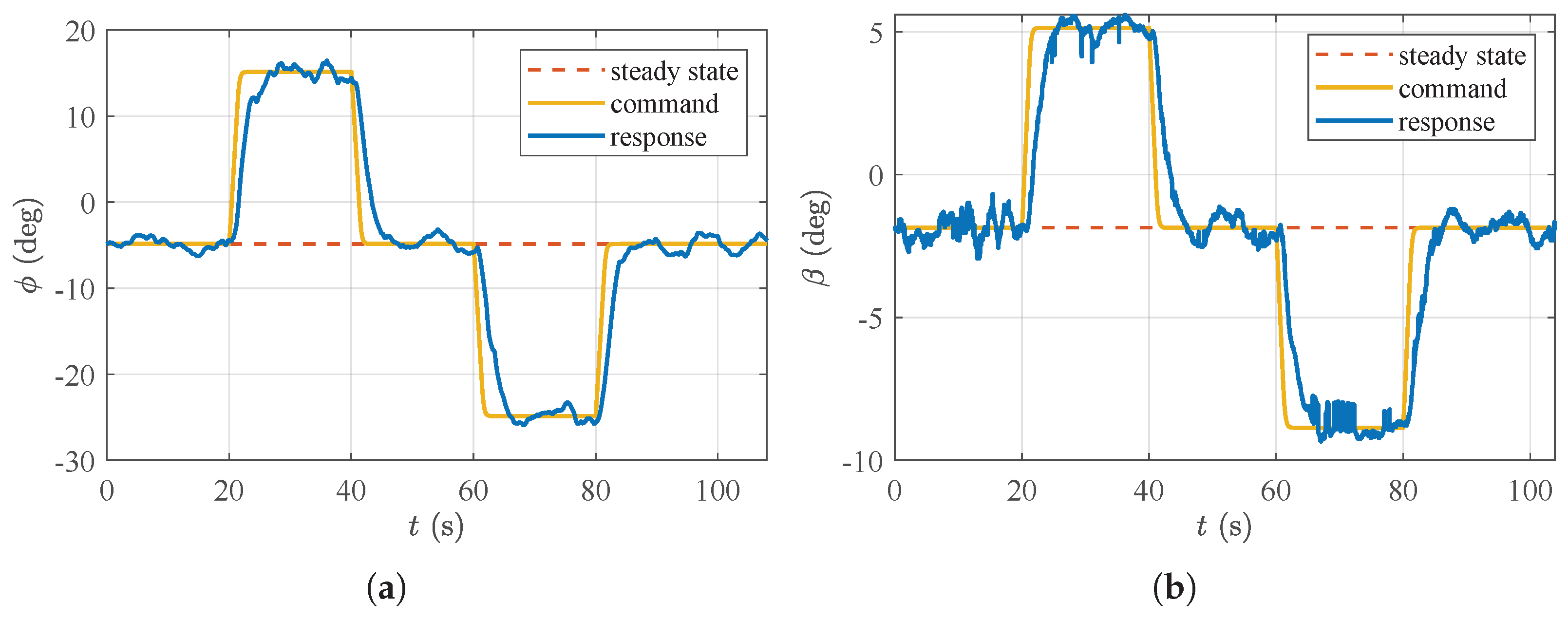
Figure 19.
Flight test results for lateral control. (a) Roll angle tracking behavior; (b) sideslip angle tracking behavior.
The flight test results for path tracking are shown in Figure 20. The aircraft makes smooth turns and follows the path defined by the specified waypoints. However, it occasionally initiates turns too early or too late, which can be attributed to the influence of wind. The inner loop aims to maintain the airspeed, while the outer loop calculates the switch distance based on the kinematic velocity. When the algorithm triggers a turn but the kinematic velocity decreases during the maneuver, the aircraft tends to complete the turn earlier than expected. Moreover, the inner-loop states strive to follow the commanded inputs, further validating the effectiveness and robustness of the applied basic controller in a real-flight environment.

Figure 20.
Flight test results for path tracking. (a) Flight path; (b) basic control states.
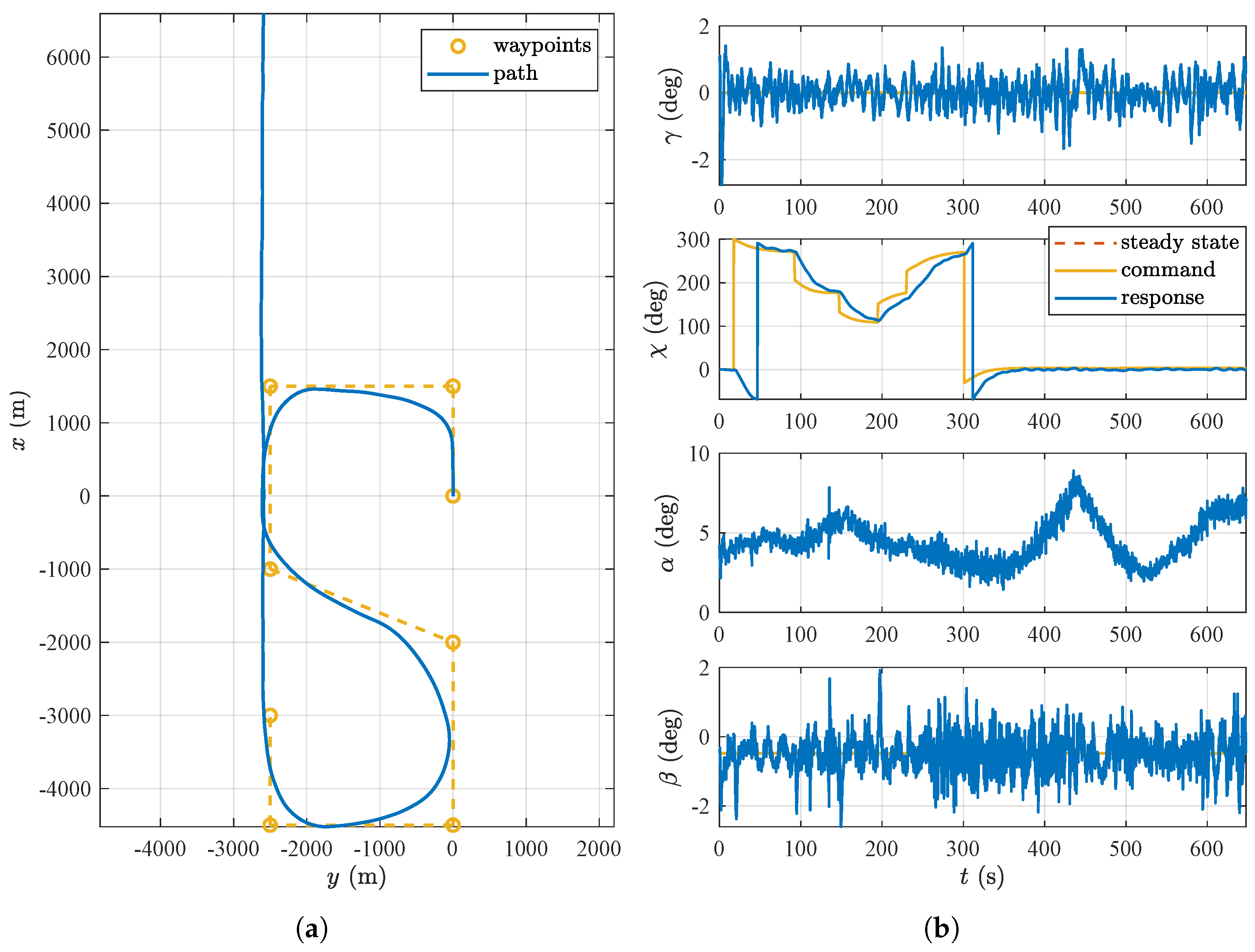
Subsequently, the implemented controller is tested in an aerotow scenario. In this flight test, the e-Genius is tasked with towing a glider while following an S-shaped path, defined by the waypoints shown in Figure 21a. Throughout the maneuver, the e-Genius is required to maintain a constant airspeed and a fixed path inclination angle , with the roll angle constrained to . In the aerotow scenario, the same control gains used in the previous scenario are applied. The towline tension acting on the e-Genius can be treated as an external disturbance. The state feedback control with integral and feedforward can effectively handle such disturbances, especially when they are low-frequency and persistent. Also, a slower turn is permitted, which corresponds to lower-frequency disturbances, further supporting the system’s ability to manage these external forces. The flight test results are presented in Figure 21. At approximately , the e-Genius completes the S-shaped path and continues to fly straight. During this straight flight, the glider moves upwards, downwards, left, and right to induce disturbances to the flight control system. Nonetheless, the sideslip angle and course angle remain stable, and the angle of attack and thrust are adjusted to modify the lift, thereby maintaining a steady path inclination angle. The results demonstrate that the flight control system effectively maintains stability and follows the desired path despite variations in towline tension and other external disturbances, highlighting its robustness in real aerotow scenarios.

Figure 21.
Flight test results during aerotow. (a) Flight path; (b) flight states.
6. Conclusions and Perspectives
This paper presents the updated configuration of the research aircraft e-Genius, designed to serve as a flying testbed for automated electric aerotow. A key focus is the implementation of highly efficient, high-performance propulsion and battery systems to reduce the energy demand of aerotow operations. The components of these new systems are compared with those of the previous setup. Another primary aspect of this study is the integration of an AFCS to enhance flight safety and efficiency. The development of the AFCS follows a structured approach, starting with modeling and analysis, followed by controller design and assessment, and concluding with deployment and validation.
Following these modifications, a flight test campaign was conducted to evaluate the aircraft’s basic performance, with a particular focus on climb performance and recuperation tests. The flight test results confirmed the expected performance of the propulsion and battery systems, with the exception of the thermal behavior of the existing AC-cables connecting the electric motor to the inverter. These cables were not adequately sized for prolonged high-power operation but could not be easily upgraded within the scope of this study, thereby limiting the attainable operating duration and, consequently, the maximum reachable altitude at higher climb power settings above approximately 50 kWe. However, this limitation did not prevent the successful demonstration of e-Genius’s fundamental capabilities as a towplane.
The regenerative braking function of the propulsion system enables energy recovery during the high-rate descent that typically follows an aerotow after the sailplane’s release. A significant portion of the potential energy, which is usually dissipated and wasted in conventional, fossil fuel powered towplanes, can instead be redirected to charge the battery. The obtained value for the efficiency of the recuperation with the e-Genius´ standard propeller is only slightly less than one obtained by a study that investigates a propeller which is optimized for recuperation [27]. Adverse effects of the use of in-flight recuperation on battery cycle life have not been investigated and could be subject to further research.
Next, a series of manually flown aerotows was conducted, starting with lightweight single-seater sailplanes. With further positive results and demonstrated performance reserves, larger double-seater sailplanes with a maximum TOM of 750 kg, the highest allowed, were towed. The test results demonstrated that battery-electric propulsion systems can be viable for towplanes, offering significant reduction in energy demand for these flight missions. When compared to even a modern TMG optimized for aerotowing (e.g., Akaflieg Stuttgart fs35), a reduction in primary energy demand of 13% (worst observed number) to 40% (average) could be demonstrated. The reduction in energy demand reaches a factor of 3 when on older design such as the Robin DR400-180R is used for comparison. This airplane is however still widely in service. Another significant benefit enabled by the switch of the energy source from fossil fuel to electricity is the total lack of local carbon emissions, with the potential of exclusively using green electricity, produced on-site at the airfield.
The aerotow mission, characterized by short high-power climbs followed by subsequent high-rate descents, does not require a cruise segment or long-distance coverage, making it particularly well-suited for battery-electric propulsion. This mission profile partially mitigates the limitation of stored electric energy, which is more apparent in normal point-to-point transport missions, while also utilizing the recuperation capability of electric propulsion systems. Another flight mission with a nearly identical profile to aerotowing that could benefit similarly is skydiver drops.
However, the disadvantages of battery-electric flight are not entirely mitigated by the aerotow mission profile. The low energy density of current battery technology still limits the number of possible flights per battery charge and results in higher takeoff masses compared to conventional towplanes with combustion engines. This limitation could be alleviated through the use of quick-swap battery modules, a solution supported by the towplane’s return to its departure airport. The thermal management of the propulsion and energy storage components is technically manageable, but it must be carefully considered when designing a high-power propulsion system for aerotow operations. Thermal management is the primary limiting factor for sustained high power levels, and it has been found that a single component can severely bottleneck the entire system.
After the flight tests for manual aerotow, the flight tests for AFCS are performed. The results demonstrated the system’s ability to accurately follow specified commanded states and track the given path in the complex real-world environment. Furthermore, AFCS proved to be stable and robust during aerotow operations. In the future, the flight control system can be further enhanced with additional functions, such as collision avoidance, which plans a path to avoid static or moving obstacles, and updraft exploitation, which detects thermal updrafts and plans a path to utilize them for energy conservation. The impact of the flight path optimization on energy efficiency could not yet be determined by the evaluated flight tests and is subject to further research. The AFCS has however demonstrated its ability to follow a given flight path while a sailplane is towed.
Further research based on and enabled by this study could focus on the human factors and pilot training aspects. This is because of the novelty of electric propulsion and autoflight systems in this class of aircraft and for this flight mission in particular. Usually, towpilots operate with private licenses and do not have much experience with automation when compared to commercial or airline transport pilots.
Author Contributions
Conceptualization, W.F. and A.S.; methodology, S.Z. and D.S.; software, D.S.; validation, S.Z. and D.S.; formal analysis, S.Z. and D.S.; investigation, S.Z. and D.S.; resources, A.S. and W.F.; data curation, S.Z. and D.S.; writing—original draft preparation, S.Z. and D.S.; writing—review and editing, S.Z., D.S., A.S. and W.F.; visualization, S.Z. and D.S.; supervision, A.S. and W.F.; project administration, A.S., W.F. and S.Z.; funding acquisition, A.S. and W.F. All authors have read and agreed to the published version of the manuscript.
Funding
This research was funded by the German Federal Ministry for Economic Affairs and Climate Action grant number 20Q1938D. The Article Processing Charge was funded by the University of Stuttgart.
Data Availability Statement
Data is available on request.
Acknowledgments
The authors thank the project partners Air Energy Entwicklungs GmbH & Co. KG and Garrecht Avionik GmbH for their contribution to the consortium.
Conflicts of Interest
The authors declare no conflicts of interest.
Abbreviations
The following abbreviations are used in this manuscript:
| AC | Alternating Current |
| ADS-B | Automatic Dependent Surveillance–Broadcast |
| AFCS | Automatic Flight Control System |
| AGL | Above Ground Level |
| BMS | Battery Management System |
| CAN | Controller Area Network |
| CSVP | Constant Speed Variable Pitch |
| DC | Direct Current |
| FCC | Flight Control Computer |
| FLARM | Flight Alarm |
| FRD | Forward-Right-Down |
| GPS | Global Positioning System |
| HIL | Hardware-in-the-Loop |
| HMI | Human-Machine Interface |
| HPH | High-Performance Hybrid |
| IAS | Indicated Air Speed |
| ICAO | International Civil Aviation Organization |
| IMU | Inertial Measurement Unit |
| JAA | Joint Aviation Authorities |
| LQR | Linear Quadratic Regulator |
| LSA | Light Sport Aircraft |
| MIL | Model-in-the-Loop |
| MPC | Model Predictive Control |
| MTOM | Maximum Takeoff Mass |
| NED | North-East-Down |
| PID | Proportional–Integral–Derivative |
| PIL | Processor-in-the-Loop |
| PMSM | Permanent Magnet Synchronous Motor |
| PWR | Power |
| RPM | Revolutions per Minute |
| TMG | Touring Motor Glider |
| TOM | Takeoff Mass |
| UAV | Unmanned Aerial Vehicle |
| VFR | Visual Flight Rules |
Appendix A. The NED Frame, Nominal Path Frame, and FRD Frame
The north-east-down (NED) frame is a local coordinate frame (denoted by the index O), where the x-axis points north, the y-axis points east, and the z-axis points downwards, forming a right-handed coordinate system.
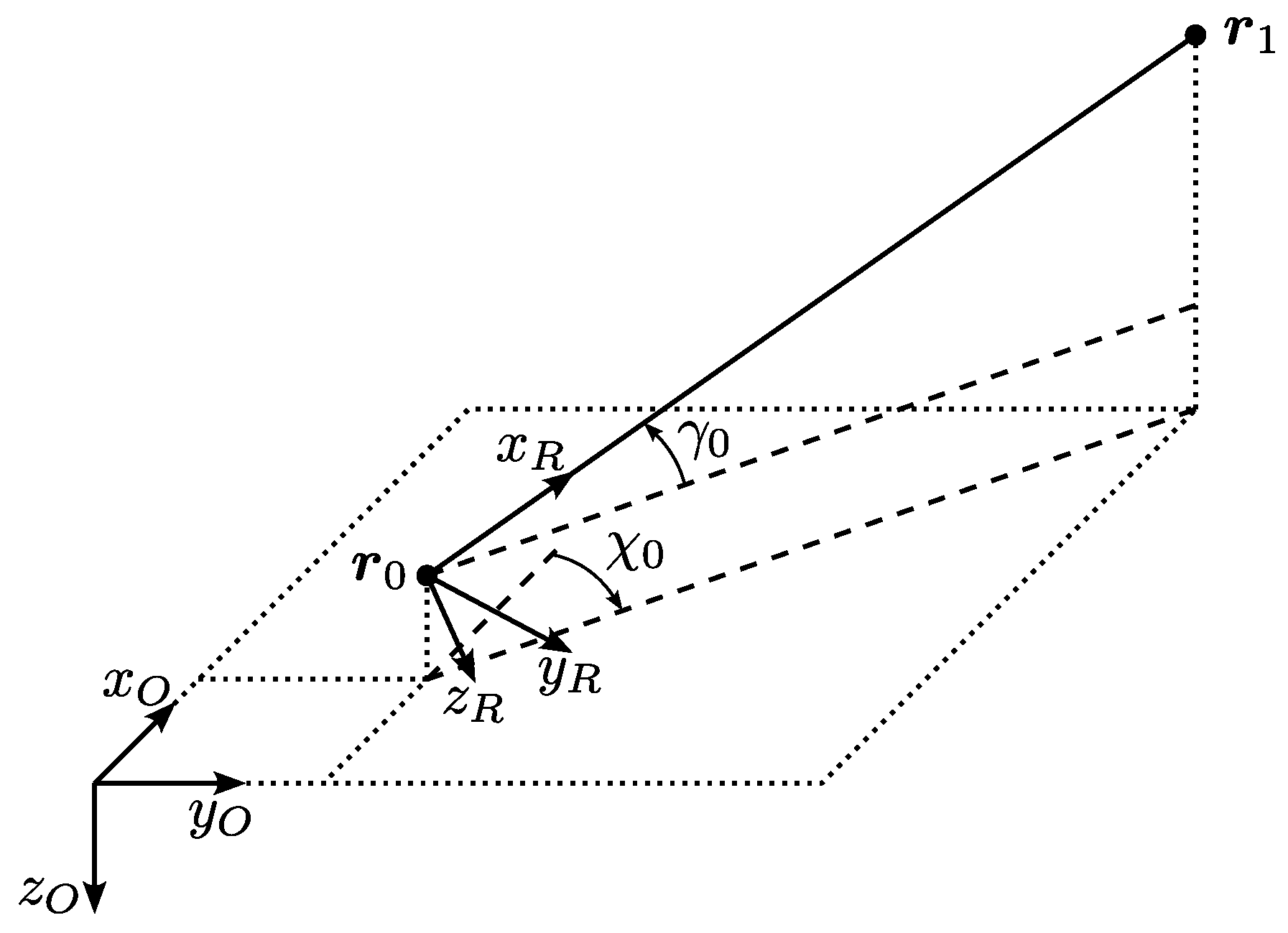
As shown in Figure A1, the nominal path frame (denoted by the index R) is defined based on the target path connecting the current waypoint and the next waypoint . The x-axis is aligned with the target path, the z-axis is perpendicular to the x-axis in the vertical plane, and the y-axis is determined by the right-hand rule.
The forward-right-down (FRD) frame is a local coordinate frame, in which the x-axis points towards the front of the aircraft, the y-axis points to the right, and the z-axis points downwards, forming a right-handed coordinate system.

Figure A1.
The definition of nominal path frame.
Figure A1.
The definition of nominal path frame.
Appendix B. Linear Model
The longitudinal motion and lateral motion are represented by the following state-space models, respectively:
Appendix C. Controller Gains
The designed controller gains for basic control and path tracking are listed in Table A1 and Table A2, respectively.
Table A1.
Controller gains for basic control.
Table A1.
Controller gains for basic control.
| Controller Type | K | H | ||
|---|---|---|---|---|
| Longitudinal | −1.3 | |||
| Lateral | N/A |
Table A2.
Controller gains for path tracking.
Table A2.
Controller gains for path tracking.
| 0.16 | 0.06 | 0.3 |
Appendix D. Overview of Conducted Aerotows
Table A3.
Overview of conducted aerotows.
Table A3.
Overview of conducted aerotows.
| Date | Type of Sailplane | Mass of Sailplane (kg) | Mass of e-Genius (kg) | Runway Surface | Release Altitude (m) | Average Climb Rate (m/s) | Energy Climb (kWh) | Energy Recuperated (kWh) | Energy Approach (kWh) | Energy Total (kWh) | Towing Efficiency (%) |
|---|---|---|---|---|---|---|---|---|---|---|---|
| 19/08/2024 | Discus CS | 360 | 825 | concrete | 1267 | 1.71 | 13.05 | 0.46 | 0.21 | 12.8 | 9.5 |
| 19/08/2024 | Discus CS | 360 | 825 | concrete | 1677 | 1.37 | 17.8 | 0 | 0 | 17.8 | 9.2 |
| 20/08/2024 | Discus 2c DLR | 430 | 825 | concrete | 1489 | 0.96 | 22.88 | 0.53 | 0 | 22.35 | 7.6 |
| 20/08/2024 | Discus CS | 360 | 825 | concrete | 687 | 2.26 | 7.38 | 0 | 0.56 | 7.94 | 9.6 |
| 22/08/2024 | Duo Discus T | 560 | 825 | concrete | 551 | 2.25 | 6.73 | 0.09 | 0.28 | 6.92 | 12.5 |
| 22/08/2024 | Astir CS | 360 | 825 | grass | 675 | 3.07 | 5.24 | 0.24 | 0 | 5.0 | 12.6 |
| 22/08/2024 | Arcus S | 610 | 825 | concrete | 863 | 2.15 | 9.11 | 0.38 | 0 | 8.73 | 15.7 |
| 22/08/2024 | B12 | 615 | 825 | grass | 579 | 2.14 | 6.63 | 0 | 0.23 | 6.86 | 14.6 |
| 22/08/2024 | Duo Discus T | 660 | 825 | concrete | 515 | 1.61 | 7.54 | 0 | 1.57 | 9.11 | 12.3 |
| 22/08/2024 | Arcus S | 666 | 825 | concrete | 396 | 1.58 | 5.87 | 0 | 0.22 | 6.09 | 12.2 |
| 24/08/2024 | Arcus S | 750 | 825 | concrete | 582 | 1.57 | 8.95 | 0 | 0.19 | 9.14 | 13.3 |
| 24/08/2024 | ASK 13 | 470 | 825 | grass | 542 | 1.37 | 8.86 | 0 | 0.3 | 9.16 | 7.8 |
| 17/10/2024 | Discus 2c | 360 | 880 | concrete | 856 | 1.64 | 9.98 | 0 | 0 | 9.98 | 8.4 |
References
- Bristell Classic. Available online: https://www.bristell.com/bristell-classic (accessed on 13 February 2025).
- Aerospool Aeroplane. Available online: https://www.aerospool.sk/index.php/aeroplane (accessed on 13 February 2025).
- Breezer B-400-6 UL Towing Version. Available online: https://www.breezeraircraft.de/en/modelle/b850-schleppversion (accessed on 13 February 2025).
- 915 iSa/iSc A/iS C24/iSc C24. Available online: https://www.flyrotax.com/de/products/915-is-a-isc-a (accessed on 13 February 2025).
- 916 iS A/iSc A/iS C24/iSc C24. Available online: https://www.flyrotax.com/de/products/916-is-c (accessed on 13 February 2025).
- Luftfahrt-Bundesamt. Bekanntmachung von Lufttüchtigkeitsforderungen für Segelflugzeuge und Motorsegler (JAR-22); Luftfahrt-Bundesamt: Braunschweig, Germany, 2001. [Google Scholar]
- fs35—Harpyie. Available online: https://akaflieg-stuttgart.de/projekte/fs35-harpyie (accessed on 13 February 2025).
- EXTRA 330 LE Erster F-Schlepp mit Elektro-Power. Available online: https://www.aerokurier.de/elektroflug/extra-330-le-erster-f-schlepp-mit-elektro-power (accessed on 13 February 2025).
- Elektra Trainer. Available online: https://www.elektra-solar.com/products/elektra-trainer-solar (accessed on 13 February 2025).
- Bundesstelle für Flugunfalluntersuchung. Bulletin: Unfälle und Störungen beim Betrieb Ziviler Luftfahrzeuge; Bundesstelle für Flugunfalluntersuchung: Braunschweig, Germany, 2022. [Google Scholar]
- Stevens, B.L.; Lewis, F.L.; Johnson, E.N. Aircraft Control and Simulation: Dynamics, Controls Design, and Autonomous Systems; John Wiley & Sons: Hoboken, NJ, USA, 2016. [Google Scholar]
- Fichter, W.; Stephan, J. Flugregelung; Springer Vieweg: Berlin, Germany, 2020. [Google Scholar]
- Choi, J.W.; Seo, Y.B. LQR Design with Eigenstructure Assignment Capacity and Application to Aircraft Flight Control. IEEE Trans. Aerosp. Electron. Syst. 1999, 35, 700–708. [Google Scholar] [CrossRef]
- Wang, Q.; Stengel, R.F. Robust Nonlinear Flight Control of a High-Performance Aircraft. IEEE Trans. Control Syst. Technol. 2004, 13, 15–26. [Google Scholar] [CrossRef]
- Wise, K.A.; Lavretsky, E.; Hovakimyan, N. Adaptive Control of Flight: Theory, Applications, and Open Problems. In Proceedings of the 2006 American Control Conference, Minneapolis, MN, USA, 14–16 June 2006. [Google Scholar]
- Alexis, K.; Papachristos, C.; Siegwart, R.; Tzes, A. Robust Model Predictive Flight Control of Unmanned Rotorcrafts. J. Intell. Robot. Syst. 2016, 81, 443–469. [Google Scholar] [CrossRef]
- Kurnaz, S.; Cetin, O.; Kaynak, O. Fuzzy Logic Based Approach to Design of Flight Control and Navigation Tasks for Autonomous Unmanned Aerial Vehicles. J. Intell. Robot. Syst. 2009, 54, 229–244. [Google Scholar] [CrossRef]
- Emami, S.A.; Castaldi, P.; Banazadeh, A. Neural Network-Based Flight Control Systems: Present and Future. Annu. Rev. Control 2022, 53, 97–137. [Google Scholar] [CrossRef]
- Schumann, L. Reduktion des Energiebedarfs Mittels Eines Batterieelektrischen Antriebs am Beispiel Eines Kleinflugzeugs. Ph.D. Thesis, University of Stuttgart, Stuttgart, Germany, 2018. [Google Scholar]
- Sineton d.o.o. Elektromotor für Hydrogenius A0911; Sineton d.o.o.: Maribor, Slovenia, 2009. [Google Scholar]
- EMRAX 268. Available online: https://emrax.com/e-motors/emrax-268 (accessed on 13 February 2025).
- Pratt, R. Flight Control Systems: Practical Issues in Design and Implementation; The Institution of Electrical Engineers: Stevenage, UK, 2000. [Google Scholar]
- Karlsson, E.; Schatz, S.P.; Baier, T.; Dörhöfer, C.; Gabrys, A.; Hochstrasser, M.; Krause, C.; Lauffs, P.J.; Mumm, N.C.; Nürnberger, K.; et al. Development of an Automatic Flight Path Controller for a DA42 General Aviation Aircraft. In Proceedings of the 4th CEAS Specialist Conference on Guidance, Navigation and Control, Warsaw, Poland, 25–27 April 2017. [Google Scholar]
- Wang, K.; Gong, Z.; Hou, Y.; Zhang, M.; Liu, C.; Chen, R. Model Based Design and Procedure of Flight Control System for Unmanned Aerial Vehicle. In Proceedings of the 3rd International Conference on Unmanned Systems (ICUS), Harbin, China, 27–28 November 2020. [Google Scholar]
- Jung, D.; Tsiotras, P. Modeling and Hardware-in-the-Loop Simulation for a Small Unmanned Aerial Vehicle. In Proceedings of the AIAA Infotech@Aerospace 2007 Conference and Exhibit, Rohnert Park, CA, USA, 7–10 May 2007. [Google Scholar]
- Holzapfel, F.; da Costa, O.; Heller, M.; Sachs, G. Development of a Lateral-Directional Flight Control System for a New Transport Aircraft. In Proceedings of the AIAA Guidance, Navigation, and Control Conference and Exhibit, Keystone, CO, USA, 21–24 August 2006. [Google Scholar]
- Erzen, D.; Andrejasic, M.; Kosel, T. An Optimal Propeller Design for In-Flight Power Recuperation on an Electric Aircraft. In Proceedings of the AIAA Aviation Technology, Integration, and Operations Conference, Atlanta, GA, USA, 25–29 June 2018. [Google Scholar]
- Mayntz, J.; Keimer, J.; Dahmann, P.; Hille, S.; Stumpf, E.; Fisher, A.; Dorrington, G. Electrical Drive and Regeneration in General Aviation Flight with Propellers. In Proceedings of the Deutscher Luft- und Raumfahrtkongress, Online, 1–3 September 2020. [Google Scholar]
- ExxonMobil Avgas. Available online: https://www.exxonmobil.com/en/aviation/products-and-services/products/avgas-100ll (accessed on 13 February 2025).
Disclaimer/Publisher’s Note: The statements, opinions and data contained in all publications are solely those of the individual author(s) and contributor(s) and not of MDPI and/or the editor(s). MDPI and/or the editor(s) disclaim responsibility for any injury to people or property resulting from any ideas, methods, instructions or products referred to in the content. |
© 2025 by the authors. Licensee MDPI, Basel, Switzerland. This article is an open access article distributed under the terms and conditions of the Creative Commons Attribution (CC BY) license (https://creativecommons.org/licenses/by/4.0/).