1. Introduction
According to the Airbus manufacturer, “each in service aircraft is struck by lightning once to twice a year” [
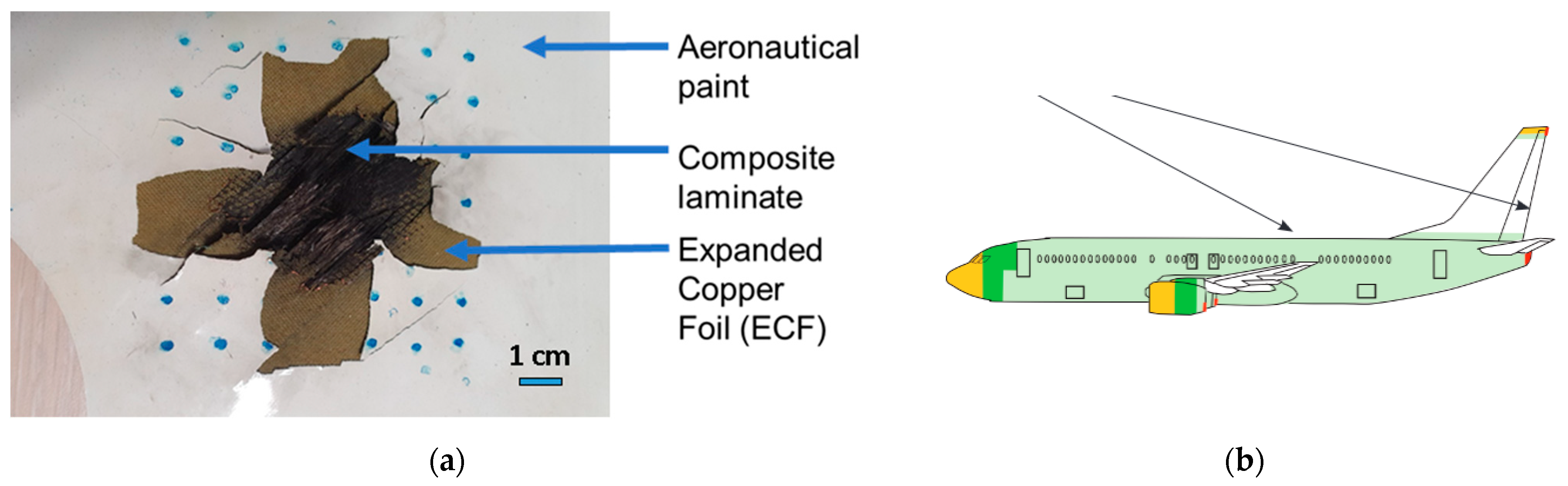
1]. As aircraft fly in the vicinity of clouds, the voltage gap needed to generate a lightning arc is reduced, leading to triggered lightning strikes that would not have occurred without the presence of the aircraft. The development of composite aircraft with reduced electrical conductivity, as well as the rise of electrical aircraft, highlights the need to improve the current lightning strike protections. Current lightning strike protections consist of a thin metallic layer, either a solid foil or an expanded foil, as a sacrificial layer on top of the composite laminate to dissipate the high current discharge. To ensure the bond between the lightning strike protection and the composite structure, as well as the aeronautical paint, it is usually coated in a dielectric resin (
Figure 1).
This protection method has proven its efficiency [
3] but does not protect the aeronautical structure entirely and implies maintenance and flying down-time to repair the sacrificed layer, resulting in additional cost [
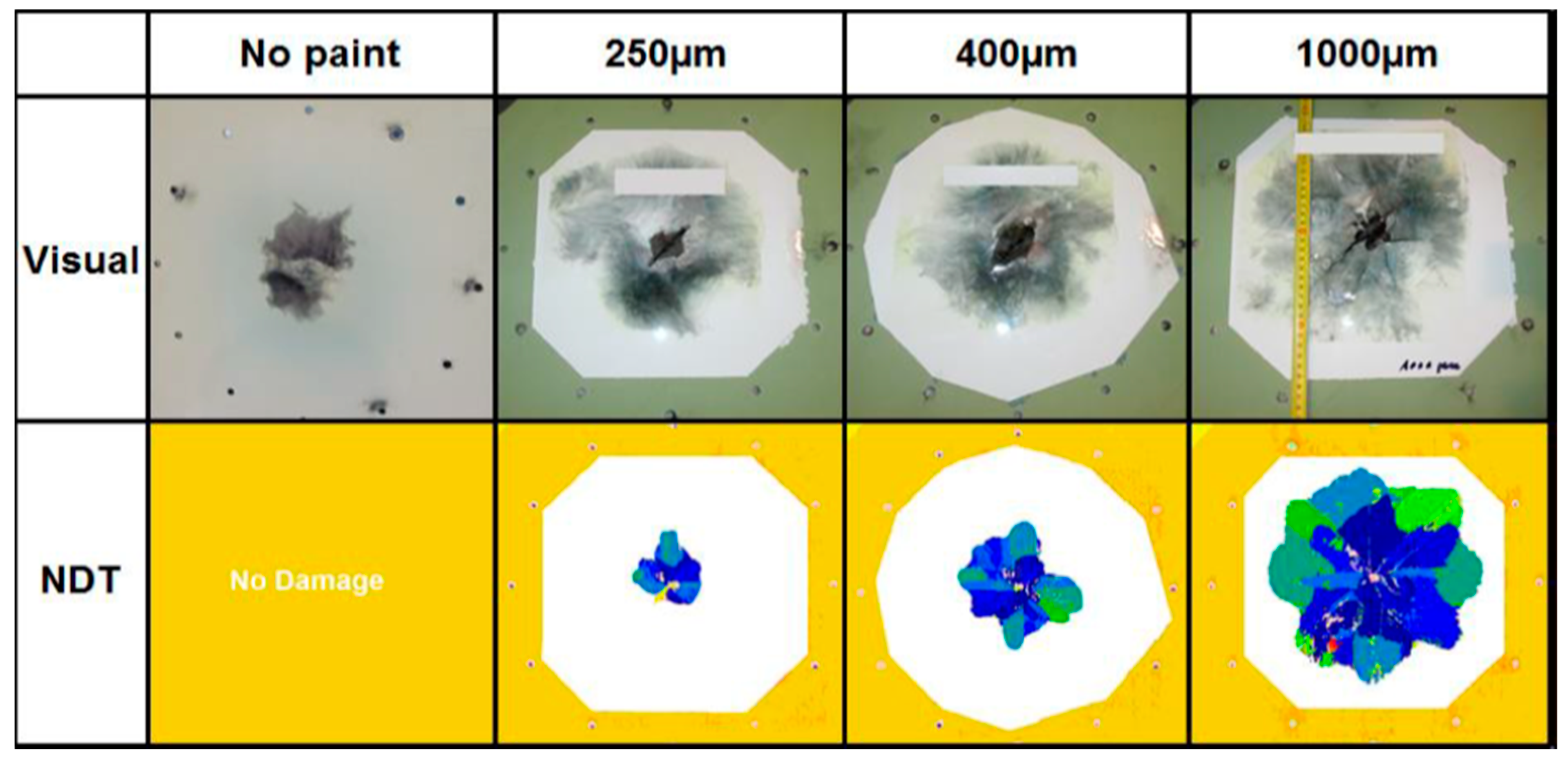
4]. Recent studies [
5] notably point out the influence of the paint thickness, increasing the damage observed in the core of composite laminates subjected to lightning strikes (
Figure 2). In addition to the constriction of the lightning arc due to its dielectric property, the paint seems to produce a confinement effect, which enhances the overpressure generated by the surface explosion [
6], as well as the amount of current plunging into the composite. These effects are notably influenced by the thickness of the paint.
Lightning strike modeling of composite laminates with lightning strike protection has made significant progress [
7], but the lightning strike impact phenomenon on a painted aeronautical composite laminate is not yet fully understood [
8]. Non-aeronautical structures such as wind turbines may not be as protected as airplanes, potentially inducing additional damage [
9].
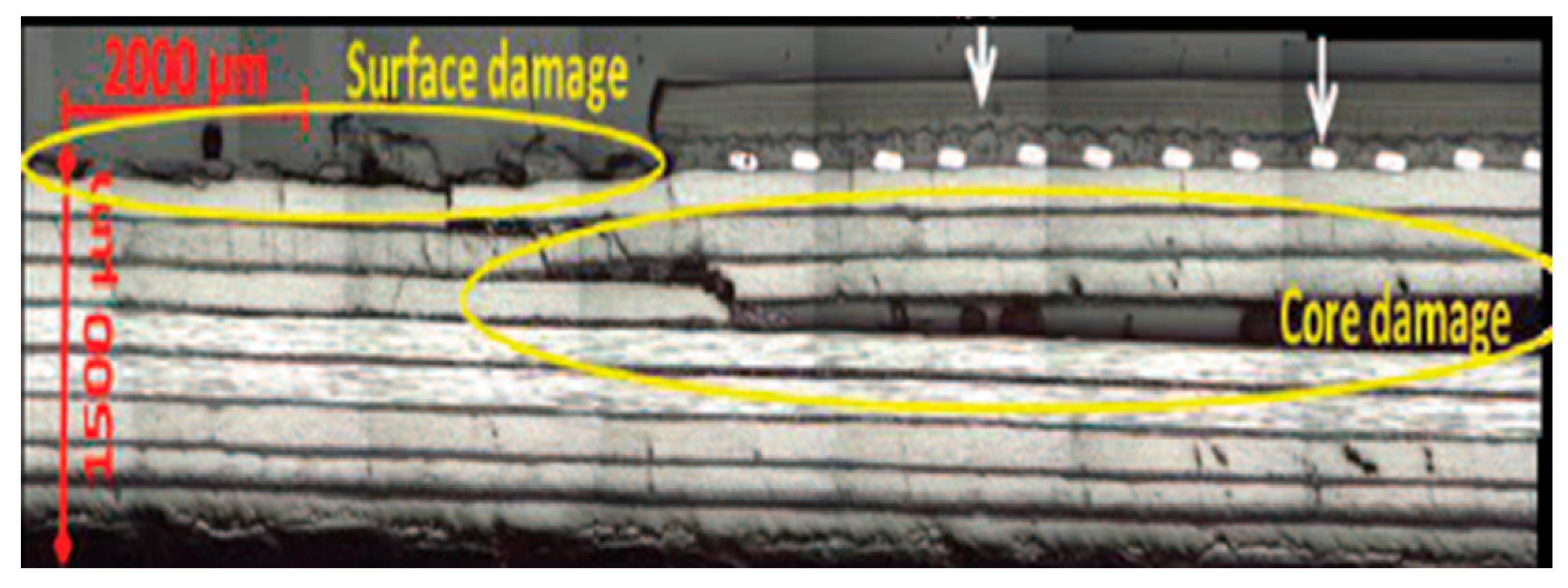
High current discharges on aeronautical structures are highly multiphysical phenomena [
10], producing both low-depth thermal damage from the heating of the metal and core mechanical damage (
Figure 3) that could even potentially affect pressurized tanks.
By studying the damage sustained by a structure with different levels of lightning strike protection, it is possible to predict the damage that could occur in unprotected areas in the event of a partial discharge from power supply cables in future-generation aircraft or power station equipment such as wind turbines. However, acquiring in situ data during experimental tests is very difficult due to the short duration of electrical discharges and the extreme electrothermomechanical conditions; thus, observations are conducted remotely [
12].
Manufacturers have not yet solved the problem of understanding this phenomenon, but solutions have been proposed. Lightning strike simulations are so complex that some manufacturers, such as Airbus, have implemented strategies for situations of increasing complexity [
5,
6,
7,
13]. They study the effects of mechanical pressure on the layers of the structure. To avoid the complexity of the lightning strike, the amplitude and radius of the equivalent mechanical load evolve over time. Other studies also attempt to model the thermal effects [
14,
15,
16]. In order to gain a better understanding of the induced thermal and mechanical loadings of high current discharge on aeronautical structures, the present work analyzes similarities in the damage generated by lightning strikes with test campaigns and numerical simulations of laser-induced shockwaves (mechanical contribution) and electron-beam deposition (thermomechanical contribution). As these experimental means are easier to instrument and monitor than lightning strike experiments, and if similarities between these experimental means are found, they could help with the development of these simulations and improve the understanding of lightning strike physics.
Improving the understanding of lightning strike physics could help aircraft manufacturers create better lightning strike protection by improving the efficiency or repairability of the protection and reducing the area weight of the protection or the associated cost [
1,
8]. Current developments try to improve lightning strike protection with conductive carbon nanotubes [
17] or a functional repair of the ECF with a conductive resin [
18].
Previous studies [
11] have shown that a mechanical impact (made with a stainless steel ball of diameter 9.9 mm and a mass of 4 g launched by a gas gun in the 50–150
range to match the post-mortem rear face displacement) is able to reproduce the total delaminated area. However, differences appear in the distribution of the total delamination area between each ply of a carbon fiber-reinforced polymer (CFRP) with a type D lightning strike (peak intensity of 100
, a duration below 500
and an action integral of
[
1]). This implies that there may be more than only a mechanical wave producing damage in the core of the structure (
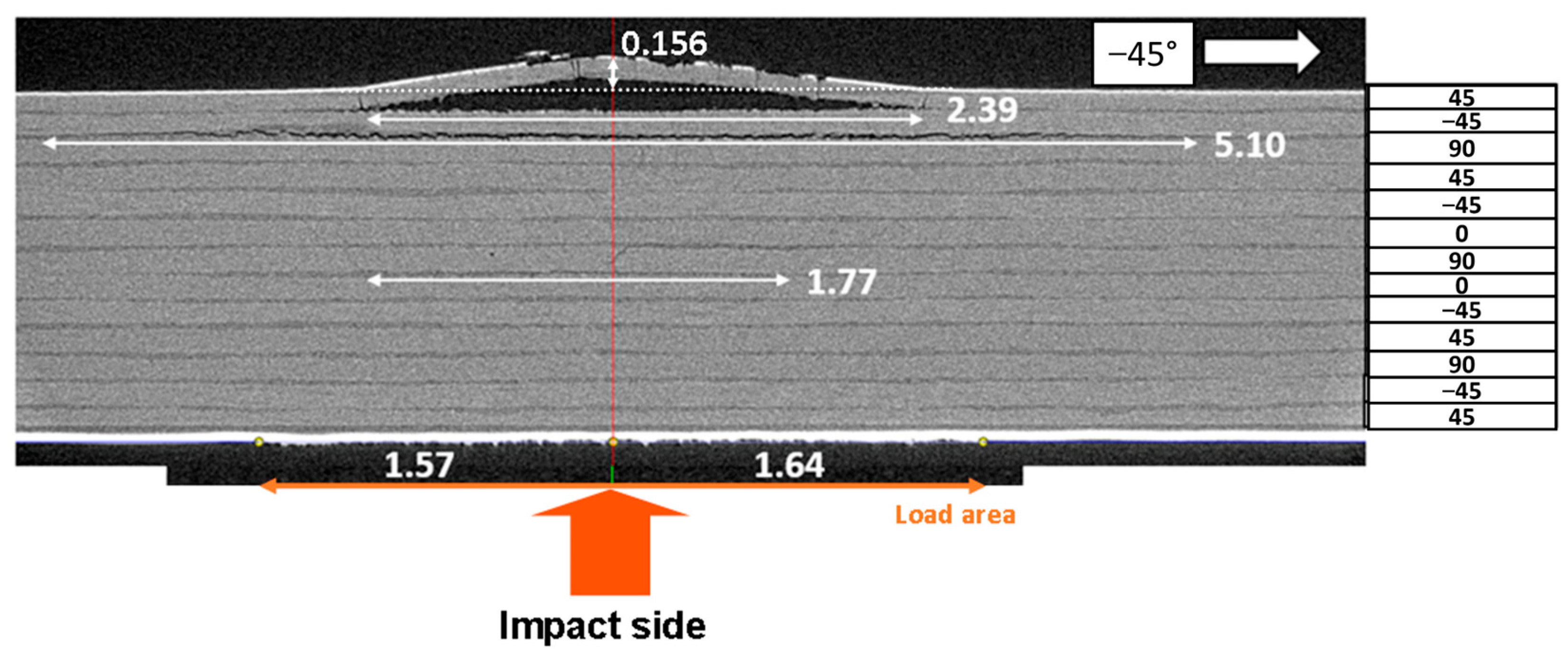
Figure 4). It is important to notice here that with a C-scan, each delaminated surface is identified from the rear face and hides the rest of the volume behind this obstacle. Because of the metallic mesh on the impact side, C-scans are measured from the rear face, which is the face opposite to the impact side. Delaminated areas have classical lemniscate (also known as peanut) shapes. Consequently, areas of one fiber direction (for example, 45°) detected in the interfaces close to the observation face hide areas of the same direction in the interfaces that are closer to the impact face. This is why only larger delaminated areas can be detected in each orientation for interfaces that are closer to the impact face.
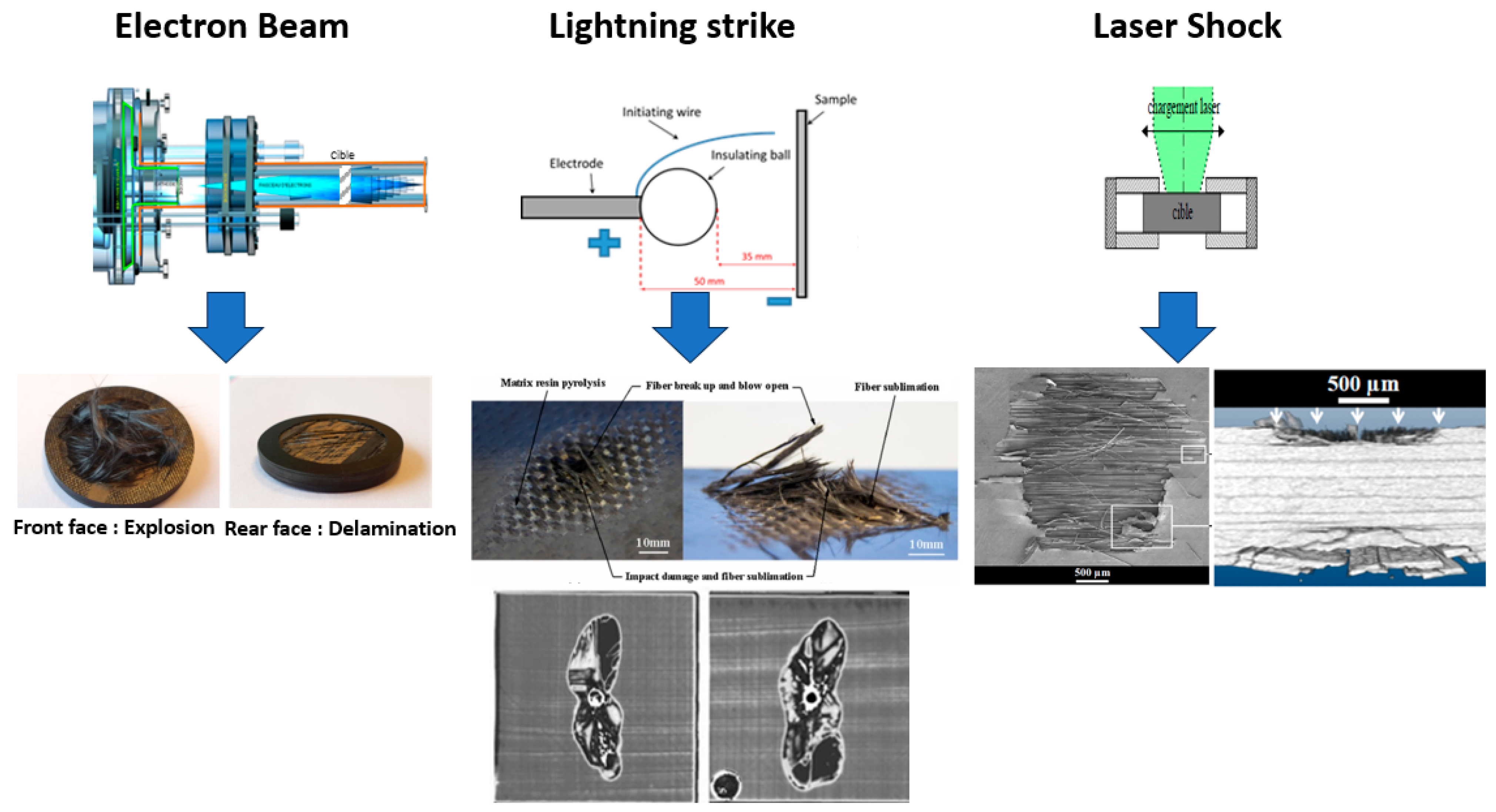
The two experimental means were chosen for the apparent similarities between the damage obtained on unprotected CFRP with laser shocks and electron beam deposition and the damage obtained with lightning strikes (
Figure 5). On the one hand, laser-induced shockwaves, while being mainly a mechanical contribution due to the negligible thermally affected thickness, induce a higher strain rate (
) than the mechanical impact
and is closer to the lightning strike strain rate as [Millen] indicates strain rates above
should be studied for a type D lightning strike. The laser shock is also useful for providing shorter impulse duration than mechanical impacts to potentially produce a delamination distribution closer to a lightning strike. This technique enables the understanding of the shock wave propagation in multi-layered material samples using numerical simulation [
19]. On the other hand, the electrical current is a flow of electrons. Studying the thermomechanical contribution of the lightning strike with an experimental mean that is potentially able to mimic this electron flow could be an asset in building an analogy of the effect of the lightning strike. Contrary to the laser shock, the electron beam also provides a volumetric loading.
2. Materials and Methods
The composite laminate manufactured by Airbus for aircraft structures is used for both the pulsed laser and electron beam test campaigns. This composite is a unidirectional carbon fiber reinforced polymer intermediate modulus aerospace (IMA) with an epoxy resin M21E. The material properties and the stacking sequence of the bare composite laminate are summed up in
Table 1.
2.1. Pulsed Laser Source
The BELENOS laser facility at the IRDL laboratory ablates the matter at a depth of a few microns, creating a plasma by inverse Bremsstrahlung, where the X photons are absorbed by the electrons of the sample, leading to its heating. The plasma is fed by the photonic loading by screening, leading to its expansion, which, in turn, creates a compression wave inside the sample by reaction that quickly stiffens into a mechanical shockwave [
23]. The laser-induced shock generator BELENOS was modeled by Tahan et al. [
24].
The characteristics of the BELENOS laser are the following:
Gaussian pulse (7.5 ns pulse duration at full-width medium height, value corrected).
Top-hat spatial distribution.
Energy output of 3.7 J at 1064 nm.
Energy density between 1 and 450 J·cm−2
A static water confinement was used to increase the impulse duration and amplify the shock produced [
25,
26].
Laser shocks were notably used to study the wave propagation across the sample by comparing the free surface velocity of the sample measured using a photonic Doppler velocimetry (PDV) system with a corresponding finite element (FE) numerical simulation.
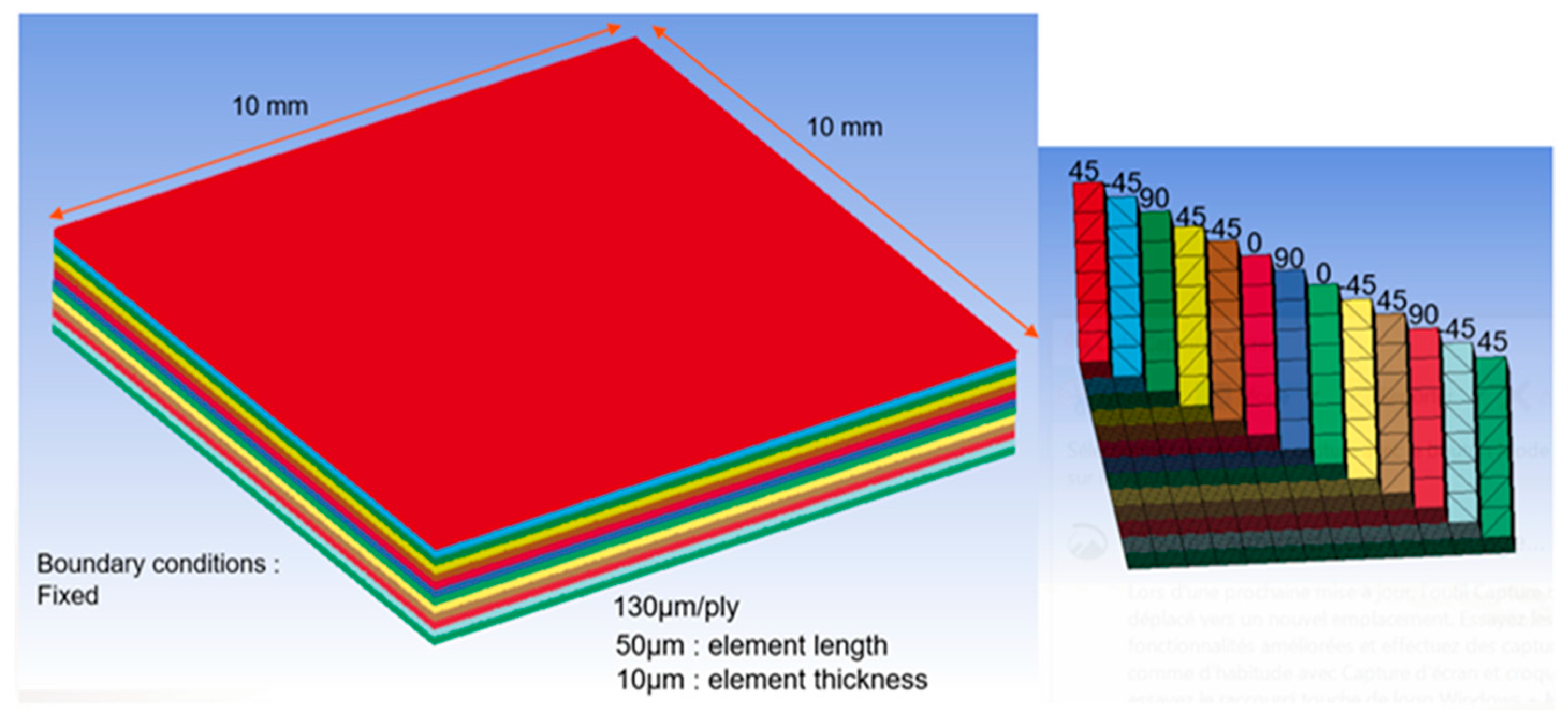
The FE model, built on the LS-PREPOST software, represents a 10 × 10 mm2 area of the bare CFRP. Simulations are performed using LS-DYNA nonlinear explicit finite element computation code. Each ply uses an oriented mesh to account for the cracking propagation depending on the stacking sequence. A mesh size convergence study determined that at least 10 elements per ply through the thickness are required to accurately simulate shock wave propagation. For the sake of simplicity, this convergence study is not presented here. The elements are fully integrated hexahedral or pentahedral, depending on the fiber direction of the ply.
The thickness of each ply was set to 130 µm to include the thickness of the inter-ply resin (
Figure 6).
Each ply uses an orthotropic material with Chang–Chang brittle failure (material card MAT_22_COMPOSITE_DAMAGE of LS-DYNA), with the failure criteria and associated values taken from the literature and reported in
Appendix A [
1,
27]:
To model the decrease in the bond strength with the damage, inter-ply contacts are modeled using cohesive contact-named tiebreaks. Tiebreak contacts were used instead of cohesive elements because the latter may hamper the propagation of the waves, especially in compression [
27]. The tiebreaks follow a linear decrease law for the stiffness of the bond once the failure criterion is met [
27]. The failure criteria and the associated parameter values are available in
Appendix A.
The mechanical pressure impulse to apply on the first ply of the CFRP is obtained with the ESTHER laser-matter interaction code developed by the Commissariat à l’Energie Atomique (CEA) [
28,
29]. The code solves 1D geometry Helmholtz equations coupled with hydrodynamics and equation of state SESAME with a finite difference method. It uses the experimental impulse of optical energy measured using a photodiode, as well as optical parameters, thermodynamical and mechanical properties of the materials, and parameters of the laser source. However, as the CFRP material is not yet supported and the reference material for the laser–matter interaction is aluminum, a 40 µm thick aluminum adhesive was added on the front face of the sample for the experimental tests to be able to determine the pressure load on the aluminum material using ESTHER. The resulting pressure pulse is available in the
Supplementary Materials.
A sensitivity study of the spatial load parameters conducted in [
30] concluded that the most sensitive parameters for the load application were the eccentricity, radial inhomogeneities, and edge slope gradient. In this paper, the modeled spatial distribution of the load is circular uniform, with a linear decrease on the edges to prevent high shear stress.
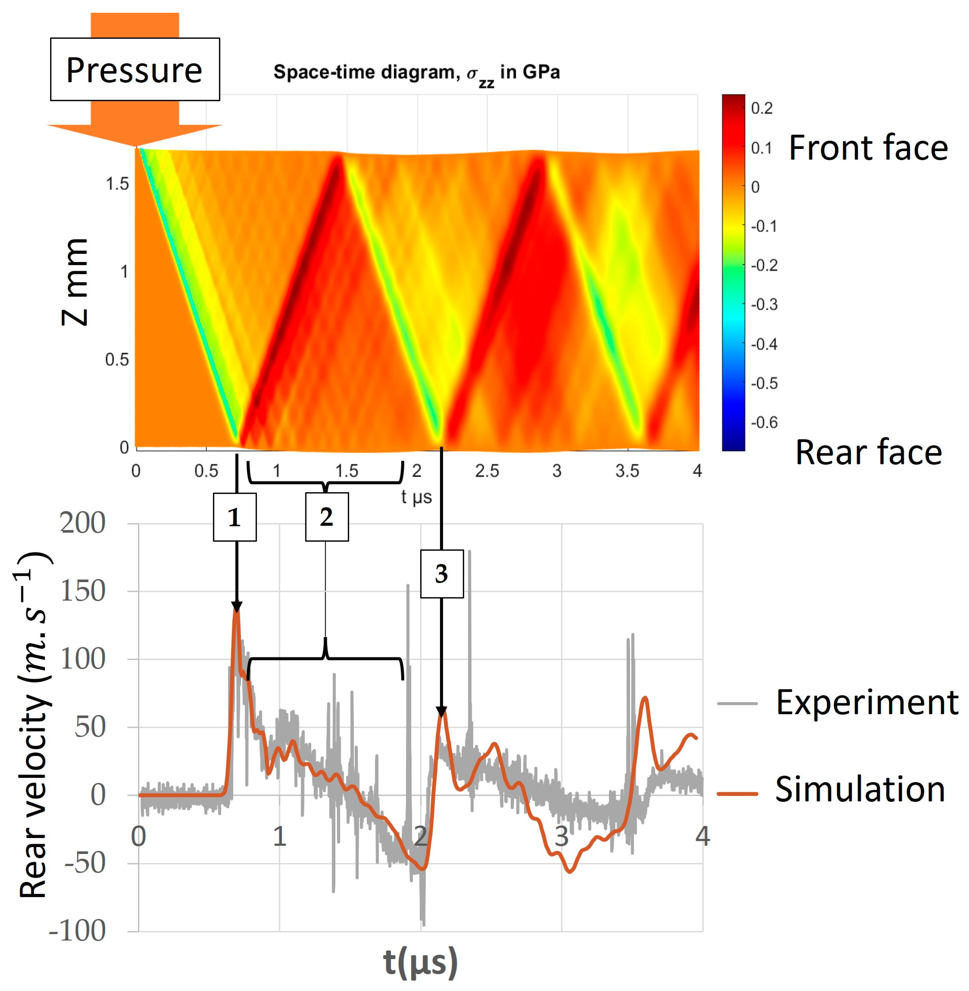
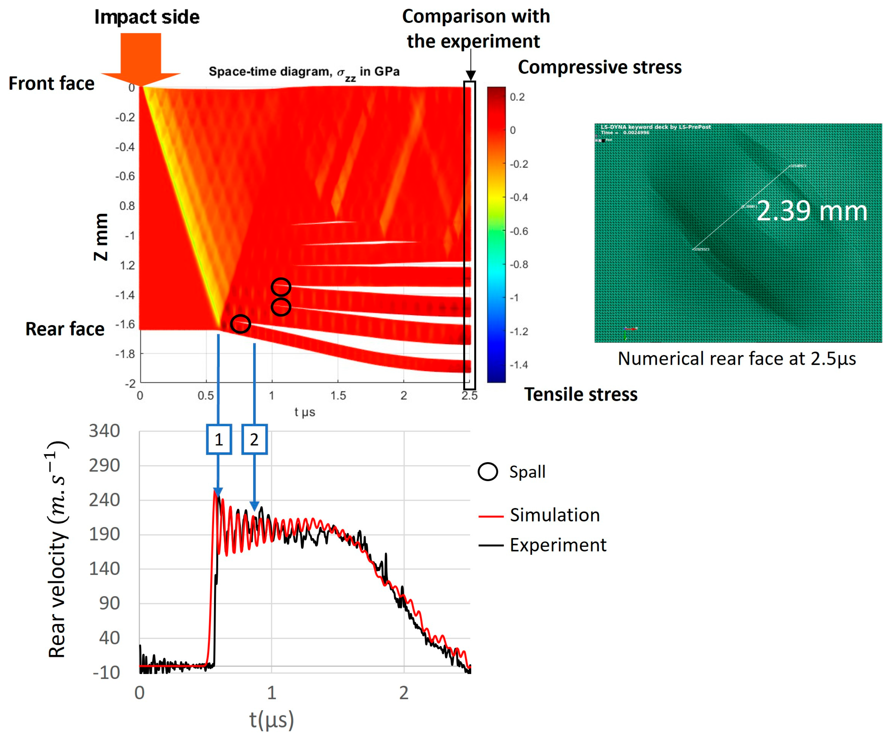
The experimental free surface velocity signal measured with the PDV system is then compared with the simulation, and a time–space diagram representing the
stress through the thickness of the modeled CFRP is used to study the wave propagation in the sample.
Figure 7 has been built by juxtaposition over time (abscissa) of the
stress along the thickness (ordinate) at the center of the target. Values for z = 0 represent the stress at the back face. Instants at which peaks of back face velocities are registered in the real experimental tests are compared with instants of arrival and rebound of the compression and tension waves and simulated velocities. Experimental sharp peaks after the first breakout (1) are mainly due to a bad signal-to-noise ratio because of the loss of the optical signal caused by the deformation of the free surface and its bad reflectivity. The validation process aimed to reproduce the maximum pressure of the first breakout (1), the period of the back and forth between the first and second breakout (1) and (3), and the shape of the release (2). The validation does not include times after (3) as the numerical velocity bump at the 2.5 µs mark is due to the 2D effects of reflection of the wave on the boundary of the mesh, leading to a nonphysical signal after this instant. Once the simulated rear velocity mimics the experimental one, the time–space diagram is thus a 1D image of a 0D measurement, enabling the study of additional data.
2.2. Electron Beam Source
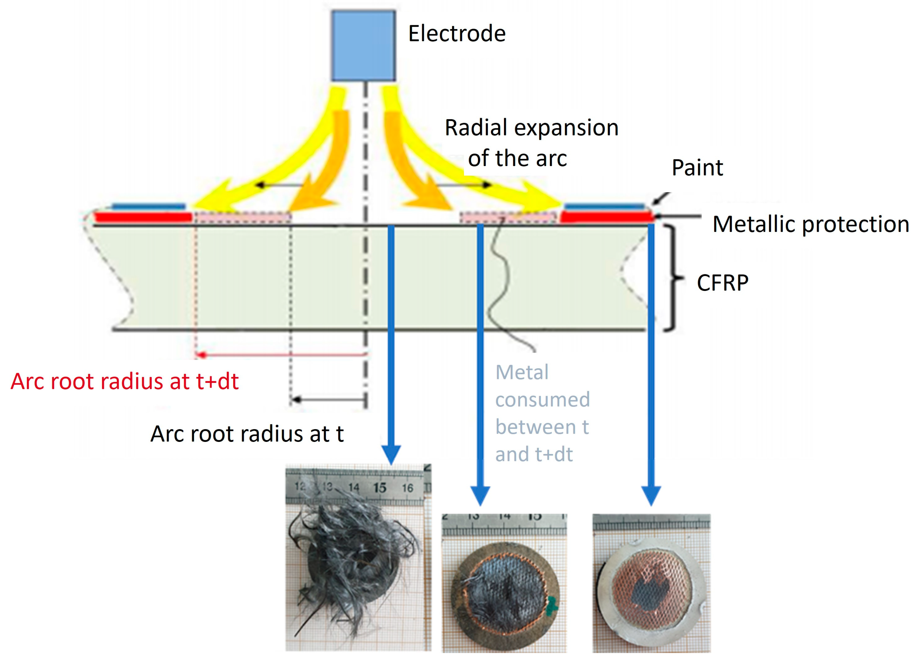
The radial expansion of the lightning arc-burned (or vaporized) metallic protection on a protected aeronautical carbon fiber-reinforced polymer laminate creates three different areas [
1]:
Near the impact location, the metallic protection has disappeared, making the CFRP bare again and directly exposed to the current and the plasma.
Close to the impact area with heated lightning strike protection but no more paint.
An area where the lightning strike protection layers are still present but may be damaged.
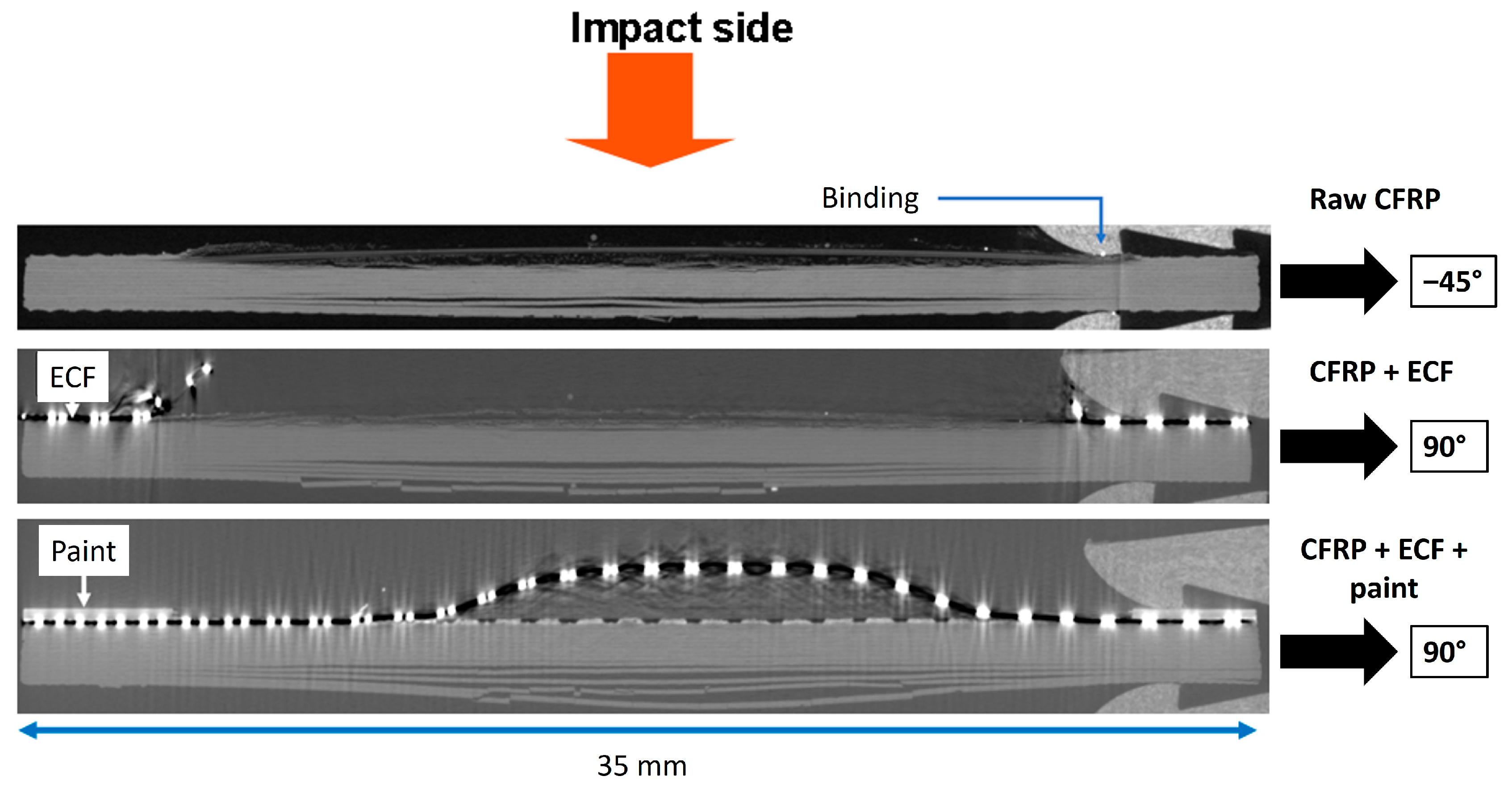
To reproduce these situations, three different coatings have been tested (
Figure 8): bare CFRP, CFRP with an expanded copper foil (ECF) protection, and CFRP with ECF and with 400 µm of aeronautical paint covering. The 400 µm thickness of the paint was chosen so that it falls within the range of thickness of commercial airplanes, and the thermal stress produced by the lightning current flow is negligible [
1]. The samples were kindly provided by Airbus.
The studied lightning strike protection is an expanded copper foil 195 (ECF195 of DEXMET Cie [
31]) with a surface density of
coated in resin. Its dimensions are summed up in
Figure 9 [
1].
The polyurethane paint is 400 µm thick, and the density has been measured to be
[
1].
The STAEL electron beam facility hosted by NUCLETUDES enables one to focus an energetic electron flow on a target diameter of a few centimeters. The electronic loading interacts with the sample through electronic collisions, and the production of X photons is due to the Bremsstrahlung. These interactions generate isochoric heating in the loaded volume up to 1 mm thick, leading to a large temperature gradient [
32]. To reach a thermal equilibrium, a mechanical shock resulting from this temperature gradient is created inside the sample.
In the selected and tested configurations, the impulse duration of the electron beam is in the sub-microsecond range. The average energy of the electrons is below 1 MeV, and a homogeneous spatial distribution and Gaussian shape pulse can be considered. Several energy density levels were studied to detect any damage threshold and produce a database of damages. Each combination of coating and energy density level was repeated between two and four times to reduce the uncertainties.
The damage in the samples is then evaluated based on microtomography analysis.
3. Results
3.1. Laser
The mechanical damage produced by the BELENOS laser on the bare CFRP is mainly due to delamination, as shown in
Figure 10. The analysis of the rear velocity signals enabled the evaluation of the energy density threshold to produce delamination inside the composite laminate between 11.8
and
with a water confinement.
Various delamination damage patterns can be observed:
The main delamination located near the rear face led to the spalling of the last ply.
While most of the damage is on the rear side of the sample, there is some delamination in the core of the laminate.
There might be some damage in the bond between the plies near the rear face, as they appear to be slightly thicker on the microtomographic view.
These damages are similar to those observed by Gay et al. [
33] achieved in the same type of materials. They were then compared to the numerical simulation using nonlinear explicit computation code LS-DYNA with the model described earlier by comparing the size of the last ply spall, as seen in
Figure 11, and the displacement of the nodes along the red line of
Figure 10 to the end state of the space–time diagram. The comparison of the free surface velocity signal between the experiment and the numerical simulation is presented in
Figure 11.
Figure 11 is representative of all experimental/simulation curves. It corresponds to a laser shock test of 30
, also illustrated in
Figure 10. For this simulation, the thickness of the last ply was reduced to 80 µm, as the rear face was polished to improve the reflectiveness of the face for the PDV measurement; the new thickness of the last ply was measured post-mortem with a microscope in an undamaged area.
The experimental rear velocity signal levels off at a mean value of around
which is the ejection velocity of the spall nearest the rear face. The velocity oscillations represent the main shock back-and-forth inside the spall, superposed with the global out-of-plane displacement due to inertial effects after delamination. The matching oscillations enabled an evaluation of the wave celerity along the thickness of the spall of
. The spalling happens when the main shock reflects on the rear face in a rarefaction wave and overlaps with the rarefaction wave in the wake of the main shock coming from the front face, leading to increased tensile stress. As the simulation has no damping, the end-state of the simulation was considered to be at 2.5 µs when the rear velocity is null.
Figure 11 shows that the simulation and the experimental frequency of vibration are the same up to 1 µs, meaning that the delaminated dimension is the same. Between around 1.7 µs and 2.5 µs, the experimental curves present small peaks probably corresponding to an increased signal-to-noise ratio in the acquisition of the PDV system, as the spalling probably modifies the reflectiveness of the rear face. Moreover, one measurement of the rear velocity limits the analysis of the 2D effects of the wave propagation inside the laminate. A multi-point PDV system could be used to study the radial propagation of the wave and the anisotropy of the damage by providing free velocity signals of various locations of the rear face. Having several comparison points between the experiment and the simulation should help refine the damage parameters and the spatial distribution of the load, leading to more accurate results.
The comparison with the microtomography view (
Figure 10) shows similarities in the rear face delamination but fails to replicate the final displacement of the rear face and the core delamination. Similar to [
33], the core damage cannot be fully replicated by only using rear face measurement. The rear face velocity signal indeed enables only the monitoring of the delamination in front of the closest to the rear face and not any other position in the thickness or any non-delamination damage.
The shorter impulse duration of the laser than the mechanical impact does not seem to significantly modify the shape of the delamination distribution (
Figure 4). An additional damage mechanism appears to be involved.
3.2. Electron Beam
The analysis of the damage of the electron beam campaign is presented with a front face picture, a microtomography side view, and a schematic average ply per ply of the microtomography view, as seen in
Figure 12.
This analysis for each combination of energy density and coating is presented in
Figure 13.
The microtomographic analysis shows the thermal damage (resin sublimation, tufting) near the front face, while the mechanical damage is in the core of the laminate (delamination and cracks). This is consistent with the phenomenon, as thermal damage results from electronic loading, while mechanical damage arises from the shock wave. Similarly, the higher the energy density, the higher the thermal damage on the front face and the mechanical damage in the core, regardless of the coating. This implies that there should be an energy density threshold beyond which thermal and mechanical affected areas overlap, producing destruction of the sample or at least a drilling. As the mechanical damage seems to progress faster than the thermal damage, the position where these contributions meet should be closer to the front face. At this position, the resin inside the plies should be sublimated, and damage should merge with the mechanical delamination and transverse cracks. By extrapolating the results, the damage contributions could meet in the fourth, fifth, and sixth ply for the bare CFRP, CFRP with ECF, and CFRP with ECF and paint, respectively. This result is a new contribution of the paper. However, this threshold was not reached experimentally, as these results were obtained after the experimental campaign.
The coatings seem to be effective at reducing thermal damage, but this is probably mainly due to the added thickness, even if the depth of the thermally affected volume depends on the density of the target. However, the mechanical damage is amplified with each added coating, especially with the paint in the global view (
Figure 14), depicting a potential confinement effect of the coatings. This is similar to the lightning strike phenomenon, in which the addition of paint above a threshold thickness increases the core damage.
As the main source of the core damage in a protected composite laminate struck by lightning is due to the sublimation of the lightning strike protection and its confinement by the paint [
5], the comparison of the delamination distribution between the lightning strike and the electron beam occurs with protected tests with electron beam tests on bare CFRP. The visual comparison is presented in
Figure 15.
For both experimental means, the first ply has been ejected, and the position of the main delamination matches, highlighting a potential analogy of effect in the core delamination between the lightning strike and electron beam deposition. To our point of view, this proves that damage near the current injection face of protected aeronautical panels is mainly due to thermomechanical loads themselves generated by the complex phenomena arising in the LSP layers during a lightning strike.
4. Discussion
In this study, the mechanical and thermomechanical load contribution to the damage observed on protected (lightning strike protection and paint) aeronautical CFRP laminates subjected to lightning strike were evaluated by trying to find analogies of effect and damage using other experimental means. These contributions were studied separately using laser shocks delivering a sole mechanical contribution and electron beam deposition delivering the thermomechanical one.
The laser shock experimental tests and numerical simulations were carried out in parallel. Simulations are validated on the one hand through the good agreement between experimental and numerical measures of the rear velocity and the final ply spall size on the other hand. The simulation is then used to analyze the shock propagation in the composite laminate, giving a scenario of delamination generation due to this purely mechanical impulsive load. It is shown that the first arising delamination is due to a spall effect, which is a direct consequence of the first shock wave reflection. The dimension and oscillation frequency of this spall are well captured by the simulation. The numerical simulation produces residual delamination distributed throughout the thickness, which more closely resembles a lightning strike. It is then concluded that the mechanical shock in both situations is responsible for delamination, which creates the spall. This delamination creates a barrier for the shock wave propagation, which is trapped in a smaller upper thickness. For the laser, the delivered energy creates an isolated large delamination. The distributed shape of the delamination in the upper limited part of the thickness after a lightning strike proves that mechanical shock is not the main contributor to the damage distribution. The presented work, therefore, confirms the conclusions of previous studies [
11].
Electron beam deposition provides an additional thermal contribution by the isochoric heating of the matter while maintaining a second mechanical load by the production of a thermomechanical shock. Thermal surface damage, as well as core mechanical damage with some delamination distribution produced by the electron beam on a bare CFRP, present similarities with the one produced by a lightning strike on a CFRP laminate protected by ECF and paint. Another similarity is demonstrated in the amplification of mechanical damage for an electron beam deposition on a protected CFRP laminate versus a bare CFRP. These different similarities seem to highlight a potential analogy of load-induced damage between electron beam deposition and lightning strikes.
The scenario proposed to analyze the contribution of the purely mechanical shock and the thermomechanical one shows that the complex multiphysical events that arise in the protection layer of a CFRP aeronautical laminate during a lightning strike event create two major loads. An intense mechanical shock rapidly travels through the thickness, creating isolated large delamination areas opposite to the impact face. This mechanical shock is responsible for the high-frequency vibrations observed on the rear face velocity measurements of the spall [
24]. In parallel, a thermomechanical shock is generated. Since thermal effects propagation is slower than pure mechanical shock waves, they are responsible for other delamination generation and late propagations in the upper layers of the laminate. This thermomechanical shock is also responsible for the plate vibrations and lower frequency, as presented in previous studies [
1,
11].
5. Conclusions
The present work studied the mechanical and thermomechanical damage produced by laser shock test campaigns and numerical simulation and electron beam test campaigns on CFRP samples with different levels of protection to analyze the potential analogy of effect and damage with lightning strikes.
On the one hand, the laser shock results have shown a good agreement between the experimental and numerical free surface velocity. They have reproduced the size of the spall, enabled the evaluation of the wave propagation celerity through the thickness, determined a delamination damage threshold between 11.8 and 13.8 with water confinement, and highlighted the inability of a sole mechanical contribution to be the main cause of damage. On the other hand, the electron beam studies have shown promising results, with several similarities to the lightning strike phenomenon—similarities both in increasing core damage with paint coating and the apparent similarities among CFRP samples with ECF, paint struck by lightning, and bare CFRP subjected to an electron beam. In light of these results, a scenario to explain the loads produced by the complex multiphysical phenomena in the protection in the event of a lightning strike is given. This scenario implies two major damage phases: the primary damage is due to a mechanical shock that creates delamination near the rear face, while the secondary damage is produced by a slower thermomechanical contribution generating core delamination and front face damage.
Developing this analogy could help composite manufacturers qualify their materials for high current discharge using electron beam testing as a preliminary or complementary test to lightning strike testing on large-scale aeronautical structures. Both laser shocks and electron beams use less energy and seem easier to manage. This method provides insight at the ply scale and enables in situ measurements due to the absence of strong visual and electromagnetic disturbances [
12]. Eventually, as lightning strike physics are not yet fully understood, its impact on protected composite laminate is hard to model; the lower complexity of the electron beam deposition phenomena could be used to improve the development of thermomechanical material models for simulations.


 ,
, 