Article

Modelling of the Power Demand of Peripheral Aggregates of an Airborne Fuel Cell-Based Power System †

Liebherr-Electronics and Drives GmbH, 88131 Lindau, Germany
Presented at the 14th EASN International Conference, Thessaloniki, Greece, 8–11 October 2024.
Aerospace 2025, 12(3), 234; https://doi.org/10.3390/aerospace12030234
Submission received: 17 February 2025 / Revised: 7 March 2025 / Accepted: 7 March 2025 / Published: 13 March 2025

Abstract

:
Because of the higher energy density of hydrogen as a clean energy source, the use of proton exchange membrane fuel cells (PEMFCs) for aviation applications has become an important research topic in recent years. Unlike batteries, fuel cells require a lot of peripheral aggregates to operate properly. The peripheral aggregates of a fuel cell, which constitute the so-called balance of plant (BoP), consume a certain part of the power generated by the fuel cell stack, which reduces the overall efficiency of the fuel cell system. One of the greatest challenges in the design of a fuel cell system is the sizing of the fuel cell stack and the determination of the internal power consumption of the BoP. This paper models the power demand of the BoP of a fuel cell system based on an automotive fuel cell power system. Furthermore, the effect of flight altitude on the power demand of the BoP is investigated.

1. Introduction

With increasing air traffic in the future, decarbonization will become a major challenge in aviation. It is therefore important to ensure that future aircraft have the lowest possible CO2 footprint. This requires innovative and disruptive technologies in various areas of aeronautics, e.g., energy sources, structures, materials, propulsion systems, etc. However, to reach the emission targets set as part of FlightPath 2050 by the European Commission [1], the application of liquid hydrogen (LH2), in the form of direct burning or in fuel cell-based propulsion systems, is the most promising option. These systems generate electricity through the chemical reaction between hydrogen and oxygen, without CO2 and NOx footprints. This makes them an environmentally friendly option, significantly reducing greenhouse gas emissions and noise pollution. Fuel cell-based electric propulsion, as a disruptive technology, has the potential to be a major part of future integration of propulsion technology [2,3]. Recent investigations have revealed that as well as regional aircraft, short-range 200 pax aircraft with a 2000 km range can be operated with fuel cell-based electric propulsion, whereby the energy density of hydrogen can be effectively utilized [4]. Several demonstrator projects and publications have already showcased the potential of fuel cell-powered flight [5,6].
To generate electric energy by using hydrogen and fuel cells, supporting auxiliary subsystems, so called balance of plant (BoP) is needed. These peripheral aggregates consume a certain part of the power generated by the fuel cell stack. Therefore, the net power generated by a fuel cell system is the difference between the fuel cell stack power and the power consumed by the peripheral aggregates (BoP). This reduces the overall efficiency of the fuel cell system, according to Equation (1):
η F C S = P S t P B o P m ˙ H 2 L H V
where Pst is the power generated by the fuel cell stack, and is the product of instantaneous stack voltage; the stack current PBoP is the power consumed by all peripheral aggregates; m ˙ H 2 is the hydrogen mass flow; and LHV is the hydrogen higher heating value.

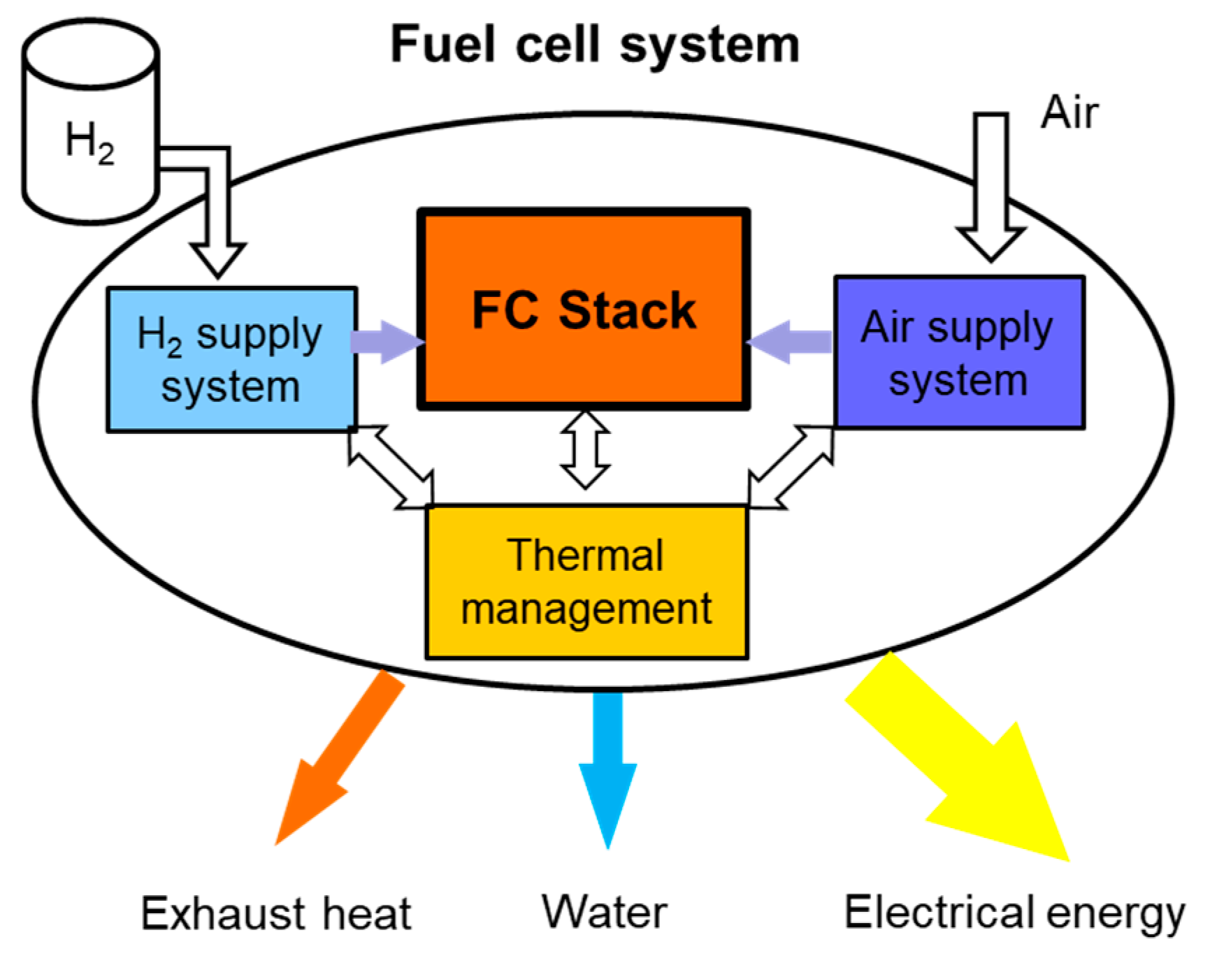
2. Balance of Plant in Fuel Cell Systems

A fuel cell stack cannot function without peripheral aggregates, and needs components around it to provide the required operating conditions. A fuel cell system has various combinations of auxiliary components, like pumps, heat exchangers, compressors, humidifiers, and control systems, to dispense the right amount of air and hydrogen, and to manage the water and thermal equilibrium [2,7]. These auxiliary components are placed in the following three subsystems, as shown in Figure 1:
  • Hydrogen supply
  • Air supply
  • Thermal and water management
A fuel cell stack needs to be fed with hydrogen as fuel at the anode side, and with oxygen at the cathode side. The hydrogen is stored in tanks integrated into the aircraft structure; however, the required oxygen is supplied by compressed air from the environment. While the tank system can provide hydrogen at a nearly constant pressure, the ambient conditions on the air side vary greatly with the flight altitude. At high altitudes in particular, the ambient pressure and temperature are too low for a fuel cell to operate effectively. Before it can be used in the fuel cell, the ambient air must therefore be compressed and heated. Water and thermal management subsystems guarantee stable operation of the fuel cell system under various humidity and thermal conditions.
The BoP power consumption is calculated as follows:
P B o P = P c o m p + P p u m p s + P f a n s + P o t h e r
The main part of the power consumption of the BoP is the power consumed by the air supply system Pcomp, which consists of a turbo-compressor driven by an electric motor and an inverter. This amounts to approximately 80% of the BoP power consumption. The Ppumps and Pfans are the power consumption of all the pumps and all the fans, respectively, which are installed in thermal management, humidification, and other subsystems. Pother is the power consumed by the electronic controller, valves, and miscellaneous devices.
One of the greatest challenges in the design of a fuel cell system is the sizing of the fuel cell stack and the determination of the internal power consumption of the peripheral aggregates. Specially, for an airborne fuel cell system, this is a challenging issue because of the great variation in operation conditions (temperature, pressure, and air humidity) as a function of altitude. These topics are very important in airborne fuel cell applications, but have not been adequately explored in recent years. This paper models the power demand of the BoP of a fuel cell system based on the experimental results of an automotive fuel cell power system, and presents a more precise mathematical model for the estimation of BoP power demand as a function of the fuel cell stack power generation. Furthermore, the effect of flight altitude on the power demand of the BoP are investigated as well.
The dynamics of the auxiliary components, mainly the air supply system, have a significant effect on the fuel cell performance, especially in systems delivering power higher than 10 kW. In particular, electrified aircraft need power ranging from a few 100 kW (general aviation) to multi- MW (short- and medium-range aviation), depending on their size, PAX, and mission.
A major part of BoP power demand is due to the air supply system, and according to experience, this amounts to about 80% of the total BoP power demand. The air supply system consists mainly of a high-speed electric motor/compressor with air bearings controlled by a high-efficiency inverter [8].

3. Modelling of Power Demand of Peripheral Aggregates

A practical approach to modelling the internal consumption of the peripheral aggregate of a fuel cell system is to use experimental data. T. Jarry et al. suggest the following linear function to estimate the power demand of a BoP [9] without any analytical proof or experimental evidence.
P B o P = 0.05 P S t m a x + 0.1 P S t
However, the investigation of existing fuel cell-based power systems for automotive applications reveals that the linear function is not a correct estimation for BoP power demand. In [10,11] the BoP power demand of two automotive fuel-based power systems are experimentally acquired and presented as graphics. Based on this graphics, this paper analyses the experiment results and suggests a more precise mathematical model for the estimation of BoP power demand as a function of the fuel cell stack’s power generation.
Figure 2 presents the experimental data of the loaded fuel cell system, with individual measurements of the power consumption of the air supply compressor, fans, and cooling pump as a function of the power generation of the fuel cell stack and fuel cell system. The scattered shaded points in the background are 10 Hz data on averaged time windows [10]. The experiments were carried out at a constant pressure and temperature, according to the authors.

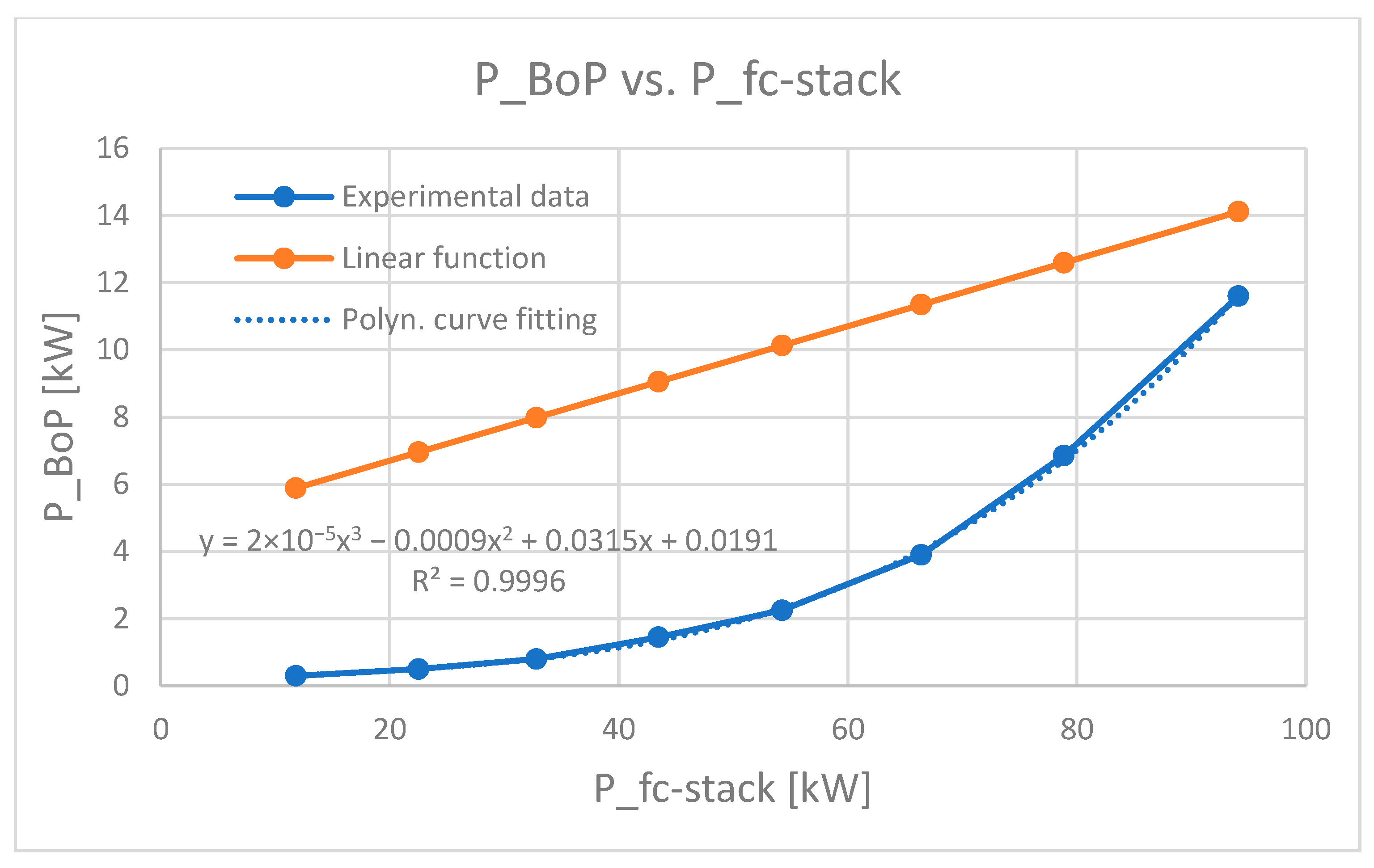
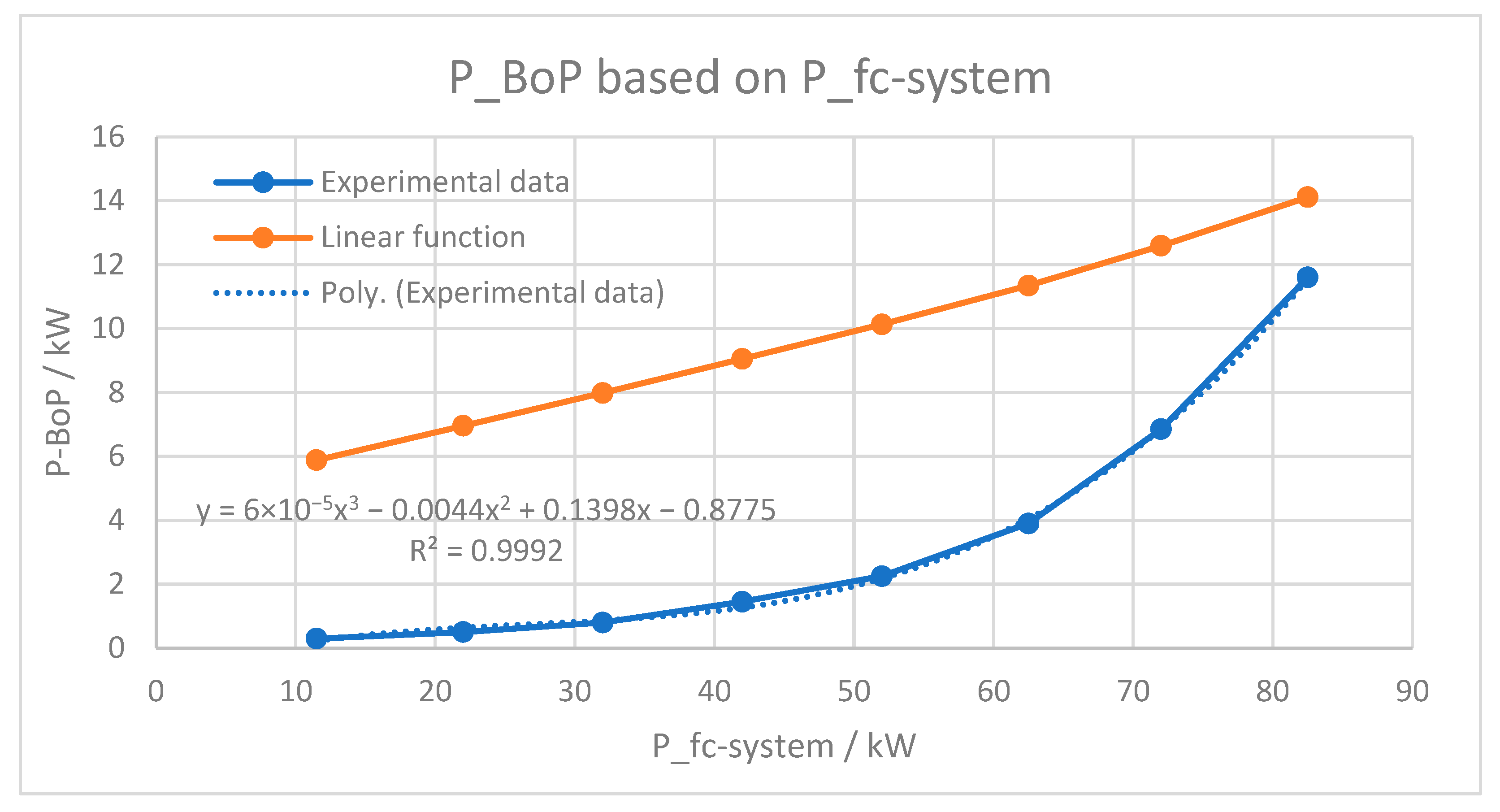
3.1. Deriving BoP Power Demand Based on Experimental Data

Based on the diagram in Figure 2, the sum of the power consumption of the peripheral aggregates is listed in Table 1. Since the measurement data were not published, these values were extracted visually from the diagram. It must be noted that the readings of the individual power consumptions from the diagram are not the exact values, and have some uncertainties, especially at lower power generation.
In Figure 3, both the calculated PBoP (from Equation (3)) and the measured PBoP as a function of the fuel cell stack power are plotted. The nominal power capacity of the fuel cell stack is considered to be 100 kW. From Figure 3, a large deviation between the data calculated using Equation (3) and the real experimental data can be identified. The deviation is reduced as the stack power increases and reaches the maximum power capacity of the stack.
A least squares curve fitting based on the experimental data leads to a third-order polynomial model with a coefficient of determination (or R-squared) of 0.9996.
P B o P = 2 × 10 5   P S t 3 0.0009   P S t 2 + 0.0313   P S t + 0.0191
where PSt is the power generated by the fuel cell stack. Using this model, one can estimate the BoP power consumption of the fuel cell system as a function of the generated stack power, and can consequently calculate the net power output of the fuel cell system. Owing to the difficulty in solving this equation., we can derive the PBoP as a function of the net fuel cell system output. For this purpose, we use the measured data in the second column of Table 1. The result is shown in Figure 4. A least squares curve fitting accordingly leads to a third-order polynomial model with a coefficient of determination of 0.9992.
P B o P = 6 · 10 5   P s y s 3 0.0044   P s y s 2 + 0.139   P s y s 0.8775
where Psys is the net power output of the fuel cell system.

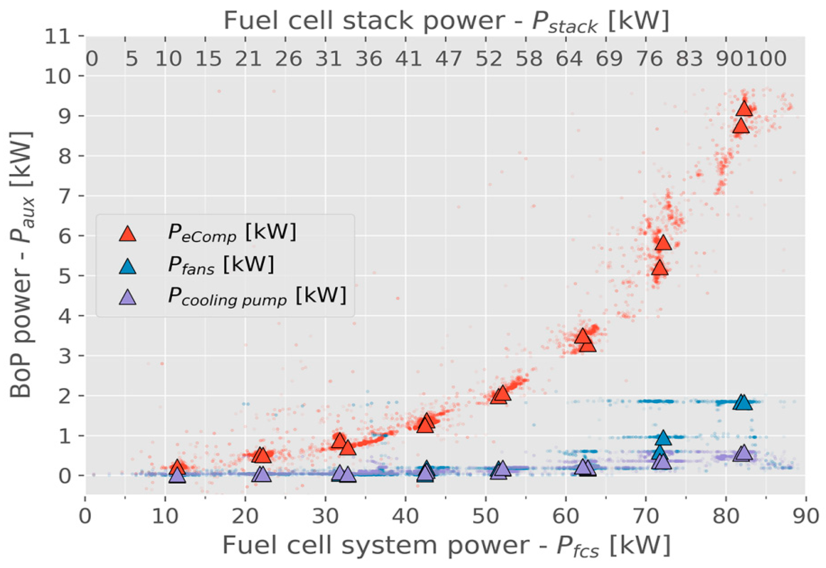
3.2. Contribution of Individual BoP Consumer Groups

The total power consumed by the peripheral aggregates is divided into three main groups, neglecting very small consumers, such as electronic controllers, and so on:
  • Hydrogen supply
  • Air supply
  • Thermal and water management
The consumers in these groups are rearranged according to the experimental data presented in Figure 2, as follows:
  • Turbo-compressor (a turbo-compressor is a combination of a compressor and a turbine, which increases the efficiency of the compressor. Both the compressor and the turbine are mounted on the same shaft, and are driven by an electrical motor)
  • Cooling pumps
  • Fans
The contribution of these devices to the total BoP power consumption is listed in Table 2. It should be mentioned that the accuracy of the readings at lower stack powers is poor, and they are not highly reliable.
The decomposition of the power consumption into the above mentioned three groups of consumers leads us to make the following rough observations:
  • The electric turbo-compressor in the air supply system is a major power consumer, consuming over 80% of the PBoP on average.
  • The power consumed by the air supply system is strongly dependent on the power generated by the fuel cell stack.
As mentioned, these data were extracted from the experiments, which were conducted under constant ambient conditions on the ground. However, a fuel cell-based aircraft power system will be exposed to very variable environmental conditions, due to variable altitude.

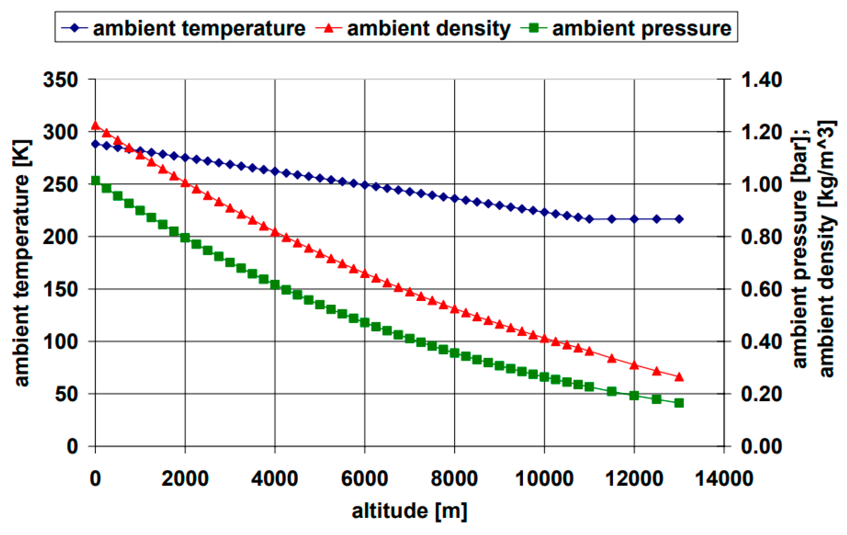
4. Effect of Altitude on Environmental Conditions

The function of the peripheral aggregates is strongly dependent on the environmental temperature, pressure, and air density. These parameters are, in turn, strongly dependent on the altitude. The dependency between the ambient conditions and altitude can be found in [12], and is depicted in Figure 5.
The altitude of a typical short-range aircraft during a normal flight mission can reach up to 9000 m. At this altitude, the pressure drops to 0.3 Bar, and the ambient temperature drops to −45 °C. These ambient conditions affect the operation of the fuel cell stack, as well as its peripheral aggregates.

4.1. Dependency of Peripheral Aggregates on Environmental Conditions

Since the power consumed by peripheral aggregates is strongly dependent on the environmental conditions, the power consumption should be considered under variable environmental conditions, such as ambient temperature and pressure.

4.1.1. Hydrogen Supply System and Thermal Management System

The operation of the hydrogen supply is independent of the ambient temperature, pressure, and density. The thermal management depends strongly on the environmental temperature and slightly on the air density.

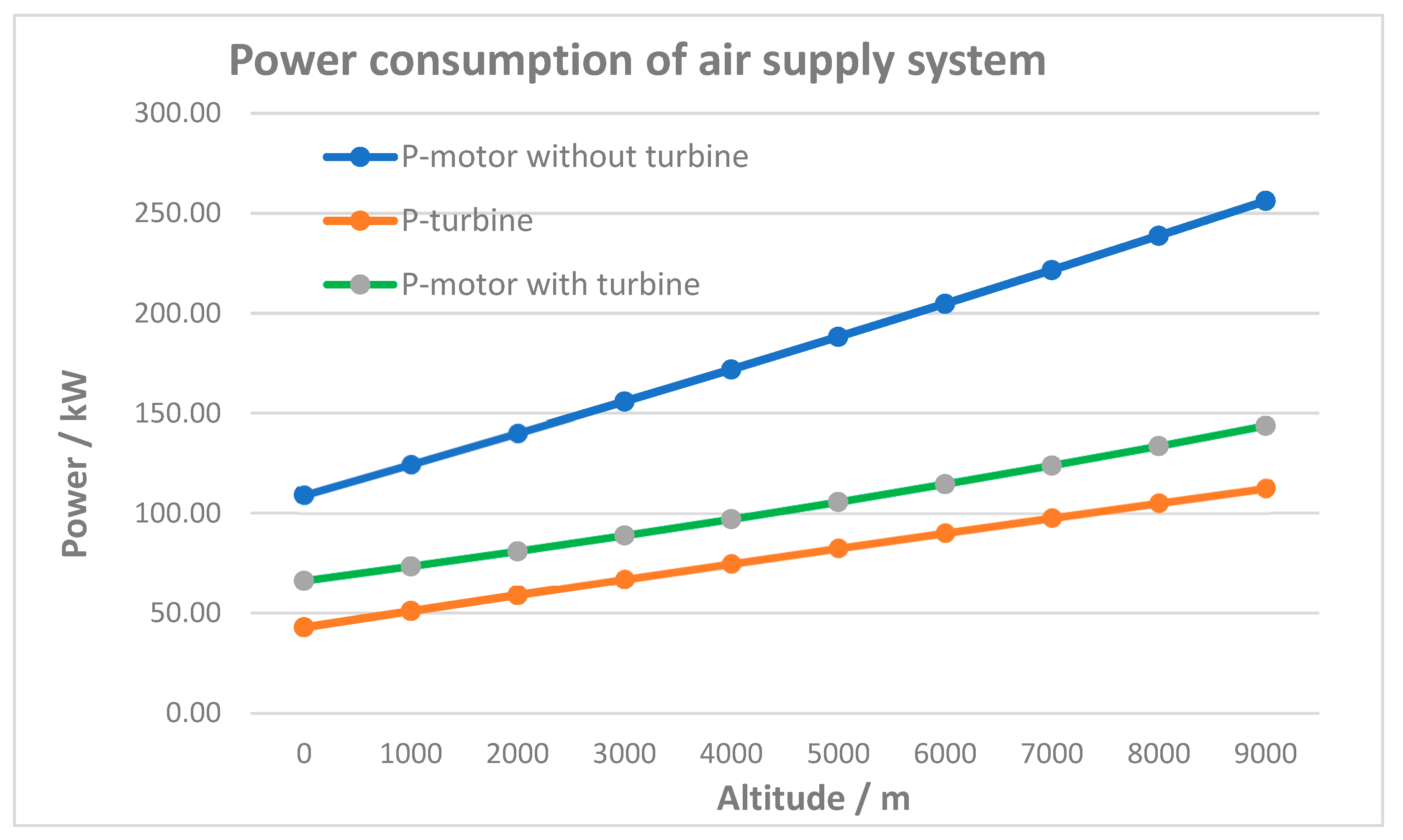
4.1.2. Air Supply System

The air supply system is strongly dependent on the environment pressure and air density, and to some extent on the temperature. A comprehensive study of air supply systems consisting of different types of air compressors and different configurations is described in [13]. Due to their high efficiency and high power density, turbo-chargers are widely used in fuel cell air supply systems, both in automotives and in aeronautics [8]. One of the major challenges in fuel cell-based aircraft propulsion is the air supply system of the fuel cell at high altitudes, since the ambient pressure, and hence the air density, as well as the temperature, decrease with increasing altitude. However, many publications do not explicitly consider these challenging conditions when designing air supply systems under high-altitude conditions. For airplane applications, a low ambient pressure and corresponding low air density require even higher compressor powers to provide sufficient pressurized air to the fuel cell stack than is required on ground, leading to a decrease in the fuel cell system’s efficiency.
The overall efficiency of a turbo-compressor, powered by an inverter-fed electric motor, is expressed as follows:
η m c o m p = η e m o t o r   η i n v   η i s e n t
where η e m o t o r is the efficiency of the electric motor, η i n v the efficiency of the inverter, and η i s e n t is the isentropic efficiency of the compressor (a compressor can be idealized as internally reversible and adiabatic, and thus as an isentropic steady-state device, meaning that the change in entropy is zero).
The air supply system must supply the FC stacks with the air flow m ˙ a at the fuel cell’s operating pressure required for generation of the desired power PSt. The net power consumption of the electric motor coupled to the turbo-compressor Pm-comp is the difference between the power required to rotate the compressor shaft and the power generated by the turbine:
P m c o m p = P c P t
The power consumed by the compressor is calculated as described in [14]:
P c = m ˙ a c p T c , i n η c p c , o u t p c , i n γ 1 γ 1
where the power generated by the turbine shaft is as follows:
P t = m ˙ e x h c p T t , e x h η t 1 p t , o u t p t , i n γ 1 γ
The net power delivered by the electric motor to the turbo-compressor is calculated, according to Equation (7), as the difference between Pc and Pt, and the power absorbed by the electronic drive from the DC source (here, from the fuel cell stack) is calculated according to Equation (6).
According to Equations (8) and (9), the power consumption of the turbo-compressor for a constant air flow m ˙ H 2 depends on the pressure ratio pc-in/pc-out. Assuming that a certain constant pressure is needed on the fuel cell inlet to produce a certain power PSt, the pressure ratio will increase with a decrease in the ambient pressure pc-in, which, in turn, leads to an increase in the power demand of the compressor. On the other hand, the power generated by the turbine, according to Equation (9), increases when the ambient pressure (here, pt-out) decreases. This situation occurs in aircraft due to the increased altitude, e.g., during the cruise phase.
This means that at higher altitudes, the decreased ambient pressure leads to increased compressor power demand, and, simultaneously, increased turbine power. This means that at high altitudes, these two power deviations compensate for each other to some extent, and the turbo-compressor power demand exhibits less of an increase compared to what a compressor without a turbine would exhibit. The following table shows the Pt, Pc, and Pm-comp = PcPt, as well as the pressure ratio for different altitudes (or different ambient pressure), for the required constant pressure of 2.3 bar at the fuel cell stack inlet.
Another parameter that affects the power demand of the turbo-compressor is the ambient temperature. According to the diagram in Figure 5, at higher altitudes, the ambient pressure and temperature both decrease, but they affect the compressor power demand in opposite ways. However, the effect of the ambient pressure is stronger than that of the ambient temperature.
From Table 3, we can calculate the ratio Pc @ground/Pc @9 km for a simple compressor (without a turbine) and for a turbo-compressor. The ratio for the simple compressor is 2.35, whereas for the turbo-compressor, it is 2.17. This means that the turbine can only slightly compensate for the effect of the altitude. However, an increase in the power of the turbo-compressor from 66 kW at ground level to 144 kw at 9 km altitude (an increase of more than 100%) is clearly visible. A comparison of the power consumption of a compressor with a turbine that of one without, as a function of the flight altitude, is depicted in Figure 6. To calculate the power consumption of the air supply system, the efficiencies of the electric motor and the inverter should be determined according to Equation (6).
The effect of the flight altitude on the power consumption of the peripheral aggregates, air supply, and hydrogen supply, as well as the thermal and water management, is qualitatively described in Table 4.
This is a very important point when dimensioning the air supply system, as well as the fuel cell stack. Let us consider an aircraft with a fuel cell system as the main power source for the entire flight, and a battery system to cover the peak power demand during take-off and landing. If we design the fuel cell stack without considering the altitude effect, the net power delivered by the fuel cell stack at higher altitudes will be less than the required power. For this reason, the power consumption of the air supply system at cruise level should be considered when dimensioning the fuel cell stack.

5. Conclusions

Unlike batteries, a fuel cell power plant requires numerous peripheral components, collectively known as the balance of plant (BoP), for its operation. These components consume a significant portion of the power generated by the fuel cell stack as internal consumption. This paper verifies the existing measurement data of an automotive fuel cell system, and develops a mathematical model for BoP power consumption as a function of fuel cell power generation. Furthermore, this paper analyzes the effect of altitude on the power consumption of the BoP. The following results are derived from this study:
  • The balance of plant power consumption of a fuel cell system is a third-order polynomial function of the fuel cell power, rather than the linear function presented in the literature [9].
  • The air supply system contributes to about 80% of the total BoP power consumption.
  • To maintain the fuel cell power generation at a constant level throughout the entire flight mission, the air supply system should be designed for high-altitude conditions. This means that the rated power of the air supply system should be 200% of the amount of power required at ground level.
  • At higher altitudes, the ambient pressure and temperature both decrease, but they affect the compressor power demand in opposite ways. However, the effect of the ambient pressure is stronger than that of the ambient temperature.
  • At high altitudes, thermal management devices (pumps and fans) consume slightly less power, but this is not enough to compensate for the additional power consumption of the air supply system.
  • High altitude has no effect on the power consumption of the hydrogen supply system.

Funding

This research is partially funded by the European Union, in the context of the Horizon Europe—Clean Aviation programme “Fuel cell propulsion system for Aircraft Megawatt Engines (FAME)”. Grant agreement ID: 101140559. For more information on the project, visit https://cordis.europa.eu/project/id/101140559 (accessed on 14 February 2025).

Data Availability Statement

The original contributions presented in this study are included in the article. Further inquiries can be directed to the author.

Conflicts of Interest

Author Nejat Mahdavi was employed by the company Liebherr-Electronics and Drives GmbH.

Abbreviations

The following abbreviations are used in this manuscript:
BoPBalance of plant
FCFuel cell
LH2Liquid hydrogen
LHVHydrogen higher heating value
PEMProton exchange membrane

References

  1. Publications Office of the European Union. FlightPath 2050. Available online: https://op.europa.eu/en/publication-detail/-/publication/296a9bd7-fef9-4ae8-82c4-a21ff48be673 (accessed on 14 February 2025).
  2. Peters, R. Brennstoffzellensysteme in der Luftfahrt; Springer: Berlin/Heidelberg, Germany, 2015. [Google Scholar]
  3. Colpan, C.O.; Kovač, A. Fuel Cell and Hydrogen Technologies in Aviation; Springer: Berlin/Heidelberg, Germany, 2022; ISBN 978-3-030-99017-6. [Google Scholar]
  4. Mc Kinsey: Hydrogen-Powered Aviation; A Fact-Based Study of Hydrogen Technology, Economics, and Climate Impact by 2050; Publications Office of the European Union: Luxembourg, 2020; Available online: https://data.europa.eu/doi/10.2843/471510 (accessed on 10 February 2025).
  5. Karpuk, S.; Freund, Y.; Hanke-Rauschenbach, R. Potential of Hydrogen Fuel Cell Aircraft for Commercial Applications with Advanced Airframe and Propulsion Technologies. Aerospace 2025, 12, 35. [Google Scholar] [CrossRef]
  6. Schmelcher, M.; Häßy, J. Hydrogen Fuel Cells for Aviation? International Society of Air Breathing Engines (ISABE), Proceedings, 2022. Available online: https://elib.dlr.de/188835/1/ISABE_2022_291_full.pdf (accessed on 14 February 2025).
  7. Klell, M.; Eichlseder, H.; Trattner, A. Wasserstoff in der Fahrzeugtechnik, 4th ed.; Springer Verlag: Berlin, Germany, 2018. [Google Scholar]
  8. De Maglie, R.; Mahdavi, N.; Dejan, J. Electronic Controlled Turbo-Compressor for Fuel Cell Air Supply System. In Proceedings of the Towards Sustainable Aviation Summit (TSAS2022), Toulouse, France, 18–20 October 2022. [Google Scholar]
  9. Jarry, T.; Lacressonnière, F.; Jaafar, A.; Turpin, C.; Scohy, M. Modeling and Sizing of a Fuel Cell—Lithium-Ion Battery Direct Hybridization System for Aeronautical Application. Energies 2021, 14, 7655. [Google Scholar] [CrossRef]
  10. Sery, J.; Leduc, P. Fuel Cell Behavior and Energy Balance on Board a Hyundai Nexo. Int. J. Engine Res. 2022, 23, 709–720. [Google Scholar] [CrossRef]
  11. Argonne National Laboratory. Technology Assessment of a Fuel Cell Vehicle: 2017 Toyota Mirai; Report # ANL/ESD-18/12; Argonne National Laboratory: Argonne, IL, USA, 2018. [Google Scholar] [CrossRef]
  12. Barchewitz, L. In-Flight Air Supply System for PEM Fuel Cells. Ph.D. Thesis, Gottfried Wilhelm Leibniz University Hannover, Hanover, Germany, 2008. [Google Scholar]
  13. Blunier, B.; Miraoui, A. Air Management in PEM Fuel Cells: State-of-the-Art and Prospectives. In Proceedings of the International Aegean Conference on Electrical Machines and Power Electronics, Bodrum, Turkey, 10–12 September 2007. [Google Scholar]
  14. Fattoruso, O. Study and Modelling of a Fuel Cell Air Supply System with Turbocharger for a Regional Hybrid Electric Aircraft. Master’s Thesis, Politecnico di Torino, Torino, Italy, October 2023. [Google Scholar]
Figure 1. A schematic diagram of a fuel cell system, consisting of an FC stack and the most important peripheral subsystems.
Aerospace 12 00234 g001
Figure 2. The power consumption of the BoP devices under steady-state operation [10]. The BoP devices are arranged in three groups: electric compressor, fans, and pumps.
Aerospace 12 00234 g002
Figure 3. A comparison of the BoP power consumption calculated using Equation (3) and the real experimental data extracted from [10].
Aerospace 12 00234 g003
Figure 4. The dependency of PBoP on the power output of the fuel cell system, i.e., the net power based on the data extracted from [10].
Aerospace 12 00234 g004
Figure 5. The ambient conditions in the stratosphere and troposphere vs. the altitude [12].
Aerospace 12 00234 g005
Figure 6. The power consumption of the air supply system as a function of the altitude, assuming a constant air pressure at the fuel cell inlet and constant power generated by the fuel cell stack.
Aerospace 12 00234 g006
Table 1. The BoP power consumption extracted from the experiment (Figure 2) and calculated according to Equation (3).
PFC-St [kW]PFC-Sys [kW]PBoP [kW]
from Figure 2
PBoP [kW]
from Equation (3)
11.8011.50.35.89
22.5022.00.56.96
32.8032.00.87.99
43.4542.51.459.05
54.2552.02.2510.13
66.4062.53.911.35
78.8572.06.8512.59
94.1082.511.614.12
Table 2. The contribution of the BoP devices to the total BoP power consumption, extracted from Figure 2.
PBoP [kW]PComp [kW]PComp [%]PFans [kW]PFans [%]PPumps [kW]PPomps [%]
0.300.2583%0.0310%0.027%
0.500.4590%0.036%0.024%
0.800.7088%0.056%0.056%
1.451.2586%0.107%0.107%
2.251.9587%0.209%0.104%
3.903.3586%0.4010%0.154%
6.855.7083%0.8012%0.355%
11.609.3080%1.8016%0.504%
Table 3. The power consumed by the compressor and generated by the turbine, as a function of the altitude.
Altitude
[m]
Pressure
[bar]
Temperature
[K]
Pc
[kW]
Pt
[kW]
Pm-tc
[kW]
01.01288.15109.1542.9666.19
10000.90281.65124.5051.0773.43
20000.79275.15140.0759.0980.98
30000.70268.65155.8667.0288.85
40000.62262.15171.8974.8497.05
50000.54255.65188.1882.58105.60
60000.47249.15204.7490.21114.53
70000.41242.65221.5897.74123.84
80000.36236.15238.74105.18133.56
90000.31229.65256.22112.51143.71
Table 4. A qualitative comparison of the BoP power consumption at ground level and at high flight altitudes.
Power Consumption on Ground Power Consumption at High Altitudes
Air supply systemhightoo high (up to 200%)
Hydrogen supply systemvery lowvery low
Thermal and water managementmoderatelow
Disclaimer/Publisher’s Note: The statements, opinions and data contained in all publications are solely those of the individual author(s) and contributor(s) and not of MDPI and/or the editor(s). MDPI and/or the editor(s) disclaim responsibility for any injury to people or property resulting from any ideas, methods, instructions or products referred to in the content.

