1. Introduction
Continuous inspections are essential for maintaining safe infrastructure and transportation systems, such as those in the aviation industry. These processes can be extremely time-consuming, labor-intensive, and risky for humans. Introducing robotic systems to assist with these inspections can significantly improve these processes.
Despite significant advancements in the Maintenance, Repair and Overhaul (MRO) industry, the in situ use of robotic systems for inspecting critical components, such as the Aircraft Fuel Tank (AFT), remains a relatively nascent area of research. The required frequency for such inspections is typically every 72 to 144 months, usually occurring during C- and D-checks, according to the Airbus A320 Maintenance Planning Document (MPD) [
1]. Implementing robotics in this context could offer numerous benefits, such as eliminating the need for humans to enter these hazardous areas, thereby enhancing safety, and potentially reducing costs if the system is successfully integrated into the inspection process [
2]. Consequently, further research in this area becomes essential.
Despite its numerous benefits, including increased thoroughness, accuracy, and recordability [
3], robotic visual inspection has not been integrated into existing human-performed processes in this context. This is due to several significant challenges [
4,
5]:
Technological Limitations: AFTs are highly constrained environments with intricate structures that pose significant navigation challenges for robots.
Reliability and Safety Concerns: The aviation industry demands high levels of reliability and accuracy in inspections to ensure safety. Robotic systems must demonstrate that they can consistently perform inspections to the same standard as human inspectors. Carrying out these certifications is a lengthy and stringent process that can delay adoption.
Integration with Existing Processes: Integrating robotic systems into established protocols can be complex and costly in the beginning. It requires significant changes, extensive retraining of personnel, and ensuring that the new systems comply with stringent regulatory standards [
6]. These factors contribute to the resistance to adopting new technologies.
Economic Considerations: The initial investment in robotic systems, including development, deployment, and maintenance costs, can be substantial. For many aviation companies, the cost-benefit ratio may not yet justify replacing human inspectors.
Building on the previous points, this work proposes the integration and development of a robotic system focused on essential visual inspection functions tailored for MRO in the AFT section. The objective is to tackle some aspects of these challenges within this domain and streamline the inspection process. The content of this paper will be structured as follows:
In
Section 1.1, a brief overview of a typical AFT inspection process will be provided to establish the necessary context.
Section 1.2 will outline the main motivations, a more detailed problem definition and the goals of this paper.
Section 2.1 will illustrate the state-of-the-art systems, highlighting the achievements and identifying gaps in existing research. Following this,
Section 2.2 will discuss a predecessor work, deriving reference key points from its methodology.
Section 2.3 will detail the workspace dimensions, definition, and delimitation necessary for the table of requirements table in
Section 2.4, as well as the key requirements for the proposed system.
Section 3 describes the hardware design and integration, the open-source software modules, and the functionalities of the robot.
Section 4 presents the inspection task experiment conducted along with a preliminary evaluation of the results. Finally,
Section 5 discusses potential improvements and future directions for further development.
1.1. Overview of an Aircraft Fuel Tank Inspection
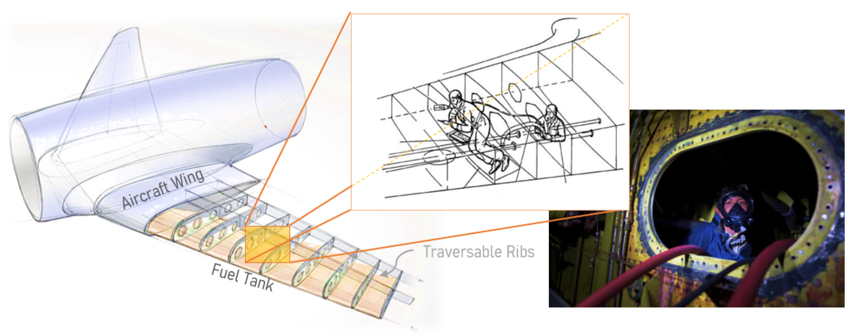
An Aircraft Fuel Tank (AFT), primarily tasked with storing the airplane’s fuel and supplying it to the engines, is typically located within the wings and at the center of the fuselage.
In the aviation industry, the regulatory institutions state specific requirements in order to provide high-quality products and services for the certification of airplanes. One example is the CS-25.993 specification [
6], which states procedures for fuel tank systems, covering visual inspections, leak detection tests, and Non-Destructive Testing (NDT) methods to maintain fuel tank integrity and airworthiness. To comply with these requirements, qualified personnel are typically required to enter a confined space and navigate through the fuel chamber compartments (see
Figure 1) as explained in the MPD [
1]. In this scenario, using respiratory and personal protective equipment (PPE) is necessary, especially for larger aircraft structures. The personnel must then take high-quality photos, and identify and categorize various types of damage, similar to the ontological taxonomy described in [
7].
During a standard inspection, the personnel generally check for [
1,
2,
4,
5]:
Cracks
Dents and deformations
Paint and coating damage
Fuel leaks
Micro-biologically initiated corrosion
The condition of the electrical wiring interconnection system, the surge burst disc (external), and the wiring harnesses above the center tank.
Such a process includes a considerable amount of preparation and involvement of various tasks, and three main blocks of preparation have to be taken into account:
Pre-Inspection Procedures: use of respiratory and PPE, fuel tank drain, the opening of access panels and vapor degassing.
Inspection Activities: safety supervision, constant communication, fuel tank entry through access panels, execution of ‘value-adding’ maintenance tasks in the region of interest (RoI) and exiting the fuel tank.
Post-Inspection Procedures: closing access panels, tank filling, removal of respiratory protective equipment, removal of safety precautions and documentation report.
The detailed diagram can be found in [
2], derived from the Aircraft Maitenance Manual (AMM) [
11].
1.2. Problem Definition and Goals
Carrying out inspection tasks in hazardous environments poses significant risks. These include exposure to toxic substances, flammable materials, and mobility challenges in confined spaces, which endanger workers and may require emergency measures [
12,
13]. In this context, invasiveness does not refer to creating new openings but rather to the potential contamination introduced by human workers. Traditional inspection methods can inadvertently damage structures or introduce contaminants, leading to issues, such as biofilm formation, increased wear, and reduced engine efficiency [
14]. These challenges underscore the need for less invasive and more reliable inspection solutions to maintain safety and structural integrity. Prompt defect identification is crucial to reducing the risk of catastrophic failures [
15,
16,
17].
Robotic solutions offering remote operation and monitoring are expected to mitigate these risks by reducing contact with internal surfaces and minimizing contamination. Studies, such as those by Heilemann et al. [
2] and the RANDE robot project [
18], highlight the significant time and cost savings achieved through robotic inspections. However, deploying robotic solutions for complex tasks requires scalable and modular infrastructures to support future advancements, as similarly emphasized in [
19,
20].
This study’s main contribution lies in addressing some of the key challenges in robotic inspection systems, particularly for complex applications like Aircraft Fuel Tank (AFT) inspections. Existing systems often suffer from excessive complexity during early development, hindering scalability and practical adoption. The proposed system emphasizes a design philosophy centered on simplicity and scalability, employing a streamlined, modular approach to facilitate inspections through incremental and achievable development steps. Although still under research, its open-source accessibility is expected to enhance adaptability across diverse industrial contexts and lay the foundation for practical, cost-effective robotic inspection technologies.
2. State of the Art, Methodology, and Requirements
This section reviews the current state of robotic systems for inspection in related environments, categorizing existing technologies using readiness levels for a preliminary structured analysis. It introduces a methodology for addressing AFT maintenance challenges and guiding the development of innovative solutions. The workspace and system requirements are also outlined, emphasizing safety components, design constraints, and user comfort and operation aspects during a robot-assisted inspection.
2.1. State-of-the-Art Systems
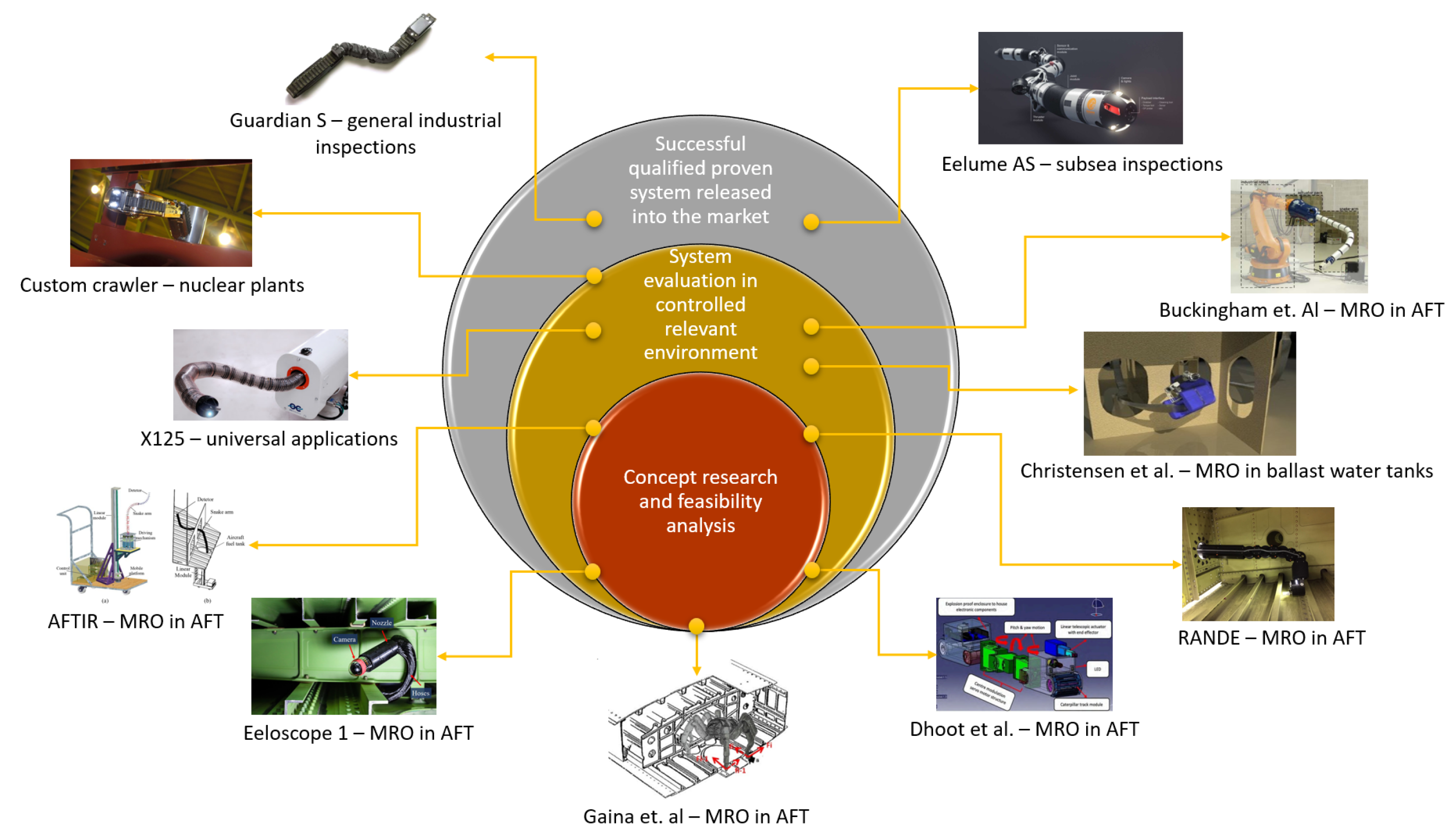
Significant innovative robotic research has been accomplished over the past decade, the main focus being on external aircraft NDT. However, the interest in internal inspections has also been growing considerably [
3]. In ref. [
3], robotic inspection systems across various domains are explored, including aviation, underwater applications, shipping, the oil industry, and nuclear power plants—the latter covering research spanning 20 years [
21].
Figure 2 illustrates the diverse mechanisms implemented in these contexts, which have been simulated or tested under certain environmental conditions.
To gain a clearer understanding of the current state of existing technologies, this work proposes categorizing them based on empirical aspects derived from the Manufacturing Readiness Levels [
29] and NASA’s Technology Readiness Levels [
30]. These guidelines outline the spectrum of technical maturity, ranging from concept feasibility to validation and verification stages. Although more detailed research into specific levels is recommended, this general approach is expected to suffice for the intended purpose of this work.
The three systems at the top have been successfully released to the market or proven effective in related environments. However, none have yet been completely integrated into AFT inspection, which remains the target application.
Continuum robots are widely recognized for their flexibility in navigating complex and confined spaces. These robots are often chosen for their ability to maneuver through intricate environments where other mechanism approaches might struggle.
Based on the current understanding of the state of the art, these robotic systems are described as follows:
In Dhoot et al. [
5], a caterpillar-shaped mobile robot designed to access large fuel tank spaces and capture real-time images and videos was developed. However, this robot has limited mobility options and does not support remote visual inspection, a crucial feature for reducing invasiveness and other aspects mentioned in
Section 1.2.
The Guardian S robot [
24], similar to the Hitachi GE [
28], is capable of navigating uneven terrains and confined spaces. However, despite its versatility and support for safe teleoperation, its invasive nature—requiring contact with surfaces—and limited flexibility render it less suitable for AFT inspection in this context.
In Guochen et al. [
8], a sophisticated continuum robot featuring a linear module and a mobile platform was introduced. The robot demonstrated high accuracy in locomotion, effectively handling load effects and curvature changes. Although promising for AFT inspection, it remains at the research stage and is not yet ready for industrial deployment.
In Buckingham et al. [
27], snake-arm robots for assembly tasks within wing boxes are examined, with a focus on design parameters and processes. While valuable, their work is more relevant to assembly than to inspection tasks.
The RANDE robotic arm tool [
18] has demonstrated potential for significant time and cost savings in invasive AFT inspection processes, achieving savings of up to 29 h. However, integrating this system into commercial applications remains challenging, as no further official information has been published since it was stated that the system is currently in the prototyping phase and awaiting use case specifications [
31].
In Christiansen et al. [
25], various locomotion techniques for ballast water tanks were explored, similar to the Eelume AS robot [
26], which is designed for underwater environments rather than AFT inspection. These systems are tailored to different environmental conditions, which makes their technical requirements differ from those needed for AFT inspection. Additionally, the locomotion techniques and geometric factors would require significant mechanical adaptation for the intended use case.
The X125 snake-arm robot [
22], used at University College London for photogrammetry, is primarily designed for assembly environments. This focus on manipulation tasks poses similar locomotion challenges as those noted for the robot in [
8]. While the X125 shows promise for future industrial and research applications, it will need additional features, such as high-resolution cameras and enhanced motion customization to adapt to the internal geometry of the AFT.
Alternative mechanisms, such as the hexapod system described in Gaina et al. [
23], have been proposed but are considered unsuitable due to maneuverability issues, instability, and the risk of damaging the tank structure.
Eeloscope 1 [
2] was an endoscopic probe designed for AFT inspections via access panels. Despite its potential to improve tank condition monitoring and digital transparency, it encountered several limitations during the development phase. Image clarity was affected by jet fuel distortion, and the tethered drive system required stronger actuators to overcome friction issues. These challenges, along with other complications, ultimately led to the decision not to continue development through this approach.
Continuum robots and other innovative solutions have demonstrated potential for AFT inspection, yet significant challenges persist in translating these technologies into practical applications. While many projects showcase effective mechanical designs and material compatibility for relevant contexts, they often lack validation through real-world testing. For instance, high-reachability techniques, as described in [
32], excel at computing trajectories to access all conceivable points but are predominantly confined to simulations.
Table 1 provides an overview of existing robotic systems, summarizing their most relevant capabilities and limitations. It is important to note that this table offers an approximation of the current state of research, reflecting a close representation of the advancements and challenges within the field, rather than an exhaustive or definitive assessment.
2.2. Derived Methodology—Design Thinking
DT is a user-oriented, multidisciplinary framework designed for iteratively achieving desirable and innovative products, and it has proven effective across many areas, as noted in [
33,
34].
The design of Eeloscope 1 [
2] focused on this methodology by analyzing and developing solutions tailored for AFT inspection within two main iterative loops: Problem Space and Solution Space. In this work, it is considered that the first three phases described in Eeloscope 1 were executed comprehensively. The process began with the Problem Space and unfolded across three distinct phases. Initially, a process chain was developed to analyze relevant stakeholders and their roles (
Understanding). A thorough data collection process followed, drawing from various information sources, such as video documentaries and interviews, to gain deeper insights and resolve ambiguities. An “Empathy Map” was also completed to capture the emotional and sensory perceptions of AFT maintainers (
Empathizing). Finally, specific maintenance issues were addressed by distinguishing between ‘value-adding’ and supporting tasks (pre- and post-processing) (
Defining). However, issues emerged during the Solution Space phase, which encompasses the subsequent three process blocks. While the morphological analysis in [
2] effectively explored various locomotion solutions by breaking down robotic inspection tasks, such as path planning and sensor selection (
Ideating), the chosen configuration led to heightened complexity. This complexity, also related to the Three-Segment Method discussed in [
32] and challenges in inverse kinematics highlighted in [
35], resulted in an overly ambitious
Prototyping phase, which in turn, hindered scalability and progress in the
Testing phase.
Thus, this work proposes adapting the final three blocks of the DT methodology described in [
2], while actively avoiding the cognitive bias known as functional fixedness [
36]. Functional fixedness refers to the tendency to perceive objects and solutions in their traditional roles, which can limit creative problem-solving. The approach of this work aims to prevent the creation of an unnecessarily complex system for tasks that could be handled by simpler and more efficient solutions. Given the challenges associated with the three locomotion variants [
2]—“Mobile Robot in an Empty Tank”, “Mobile Robot in a Filled Tank”, and “Ground-Based Robot in an Empty Tank”—this work’s focus has been narrowed to the “Ground-Based Robot in an Empty Tank”. This choice simplifies the problem and enhances applicability, particularly for defining the workspace and inspection areas, as discussed in the following section.
2.3. Workspace Definition
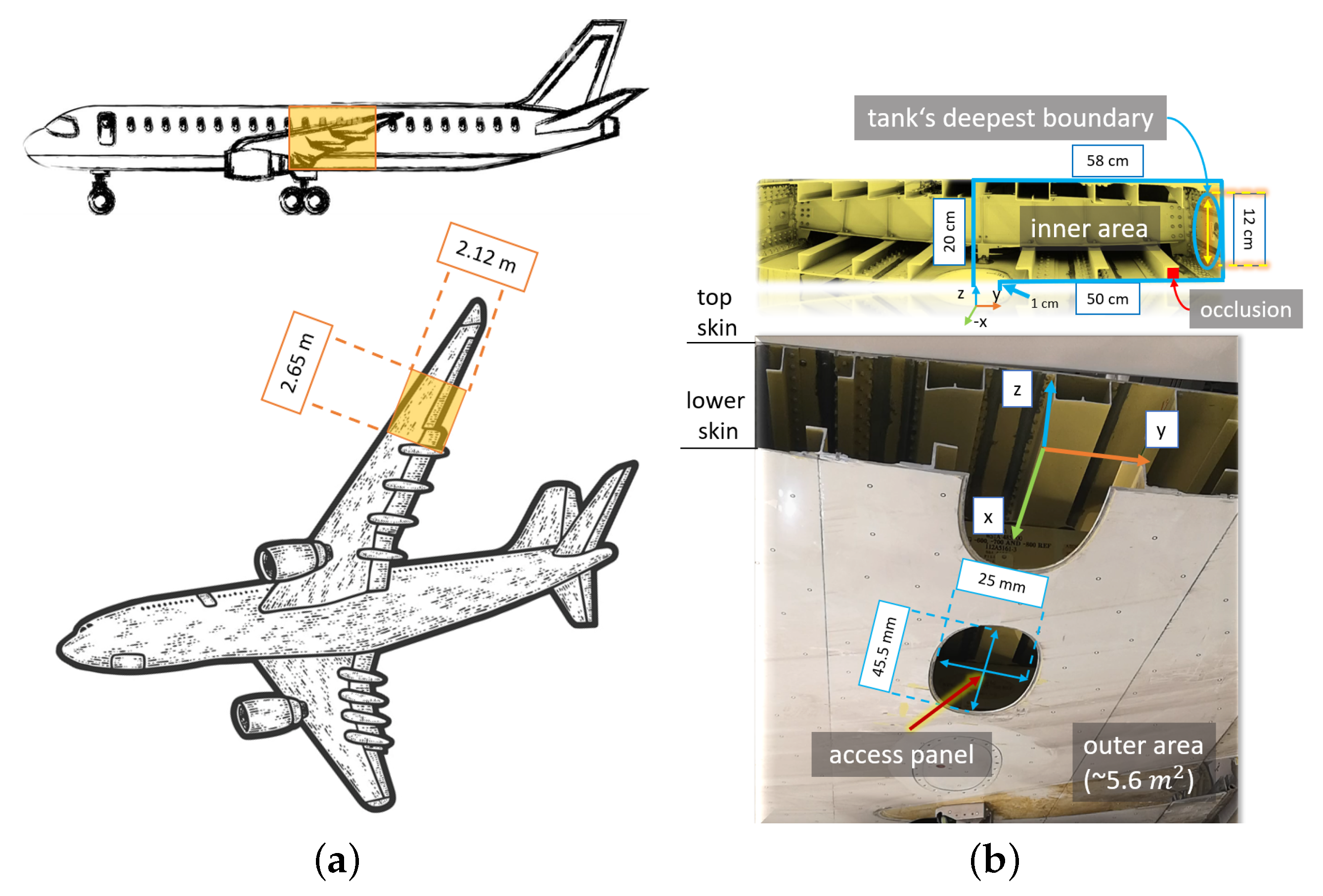
The phased-out Boeing 737-700 AFT section (see
Figure 3), which was used in Heilemann et al. [
2], is now re-utilized for this project since the object’s dimensions meet the geometric specifications and requirements in accordance to the regulatory standards [
6] for commercial aircraft.
To clarify the workspace perspective,
Figure 3a presents two side-view images of the aircraft and
Figure 3b two images highlighting the outer and inner wing sections. The goal is to perform visual inspections entering from the access panel all the way through the inner area until the tank’s deepest boundary is reached.
In principle, not only the inner surface but also the outer surfaces can be considered region of interest (RoI) for defect assessment. However, inspecting the entire fuel tank would require a complex locomotion technique, a challenge that has not yet been fully addressed by existing research and is not the focus of this work, which centers on the integration components. To simplify the workspace, the inspection is limited to the right side of the tank, as it is nearly symmetrical to the left side, allowing for the assumption that similar results would be obtained from both sides. The tank’s deepest boundary is defined as a 12-cm vertical section along the y-axis that the proposed system can reach.
Although occlusions behind the complex stringers attached to the top and lower skin of the wing can result in incomplete inspection areas, exploring these small regions is excluded from this study. Reaching these occluded areas is dependent on the configuration of the robotic system, requiring a complex camera setup and a likely agile and flexible mechanism. For now, these occlusions are temporarily omitted from the workspace. Additionally, navigation through structural ribs along the x-axis will not be addressed in this work.
2.4. System Requirements
This section outlines the key considerations for developing a table of requirements for the proposed robotic system.
Table 2 aims to find requirements to enhance operator safety, establish physical constraints for hardware design, and define general functions to ensure the effectiveness of robot-assisted inspection tasks.
This work focuses on software integration and development, while also emphasizing the importance of modularity in hardware. Given the nature of endoscopic inspections, utilizing a standard robotic arm for general locomotion combined with a rigid extension for the end effector to place sensors would streamline and simplify the development process (D-01). This modular extension would be designed to fit through standard access ports of the designated AFT allowing it to reach the tank’s deepest boundary (see
Figure 3b) (D-02).
Transitioning to robot-assisted inspections requires a thorough understanding of visual data acquisition and its application. The robotic system must feature 3D spatial perception capabilities (F-01) to precisely determine its position in the environment. Additionally, these capabilities aim at effective collision detection (S-01) and obstacle avoidance (S-02). In the event of a collision, the system should alert the user that the robot has stopped and requires manual retrieval (S-03) to prevent further damage.
Traditional approaches often require direct human interaction with hazardous environments, increasing risk and physical fatigue. Research [
39,
40] indicates that teleoperating a robot enhances safety and usability by reducing physical strain, and cognitive load, and improving user satisfaction through ergonomic design (F-02). To further reduce cognitive load and enhance safety, implementing motion planning (MP) is proposed (F-03). MP uses algorithms to automate the robot’s movements, allowing it to perform complex tasks and enabling operators to focus on other tasks, such as defect assessments and monitoring, which often rely on visual data collected from 3D reconstructions [
41] (F-01, I-01). The integration of teleoperation and MP is expected to make the system adaptable to changing conditions, with the long-term vision of a robot that can automatically navigate toward a region of interest (RoI) while avoiding collisions in confined spaces. Given that the interior of the tank is almost entirely dark, the system will require supplemental lighting to provide constant and uniform illumination during the inspection process (F-04).
For this work, two interfaces are proposed between the user and the robotic system: a Graphical User Interface (GUI) and a control interface. Typically, the GUI provides interactive buttons for user interaction with the digital environment generated by the robot’s data, making it useful for monitoring. Given the complexity of navigating confined spaces, a standard keyboard or mouse may be inadequate. Therefore, the robotic system must incorporate an intuitive control interface (I-02) to improve user interaction and operational efficiency. This interface should enable smooth manipulation of the robot’s movements and allow the simultaneous control of multiple axes for precise navigation, enhancing situational awareness, reducing cognitive load, and improving productivity and safety during inspections. Additionally, as this use case is being introduced as a robot-assisting tool, personnel retraining will be necessary. A simulation tool would be required to facilitate experience during testing, which would benefit both the development and user validation stages (I-03).
A decentralized development framework is crucial for effective modular integration and potential scalability. It enables the independent development of system components, facilitating the integration of new modules without reliance on a central system. Additionally, decentralization supports growth as new features are added, fostering collaboration and innovation through open-source contributions (NF-01).
While additional specific requirements, such as automatic surface defect detection or explosion protection certification may be necessary, they fall outside the scope of this work and will not be addressed, as they are not part of the immediate objectives.
3. Proposed System
To streamline mechanical design development, a standard robot arm will be utilized for the system’s general motion, along with a curved and rigid extension designed to fit the workspace and accommodate the necessary sensors and additional illumination components.
3.1. Robotic Arm
Although specific parameters such as precision and payload capacity have yet to be defined, utilizing a generic robot arm [
42] simplifies hardware development significantly. This standard robotic arm provides real-time joint state data and supports various control modes through open-source software packages [
43]. This component minimizes complexity while still ensuring compliance with the ISO 10218 safety standard [
44], an advantageous feature for future certification of the system. Additionally, a generic tool changer facilitates rapid switching of end effector tools, enhancing the efficiency and adaptability of inspection processes. While other robotic options may offer superior precision and higher payload capacities, the current focus on inspection tasks aligns well with the capabilities of this standard robotic arm, making additional features unnecessary. Ultimately, the emphasis on inspection rather than repair supports the decision to use this module.
3.2. End Effector Design
For the end effector extension, a cylindrical, rigid, curved structure is proposed. This design requires minimal hardware development effort and fits conveniently within the defined workspace while ensuring the sensors maintain their optimal working distance. Since the extension is a passive component, it can be tailored to meet the specific needs of various fuel tanks at a relatively low cost.
This rigid extension, now named
Eeloscope 2, consists of two main components (see
Figure 4a):
The structural tube, made of aluminum to prevent corrosion, is compatible with the tank’s internal structure and features a cylindrical geometry to enhance the weight-to-stability ratio.
The end effector encases the sensor modules and provides additional lighting.
The clearance (see
Figure 4b) is the minimum unobstructed distance required for Eeloscope 2 to reach the tank’s deepest boundary. This distance must account for the access panel dimensions (minimum 25 cm) and the bottleneck space (12 cm), which serve as the constraints for the mechanical design.
Eeloscope 2 features three short-range depth stereo cameras (Intel
® RealSense
® D405 [
45]), offset by ninety degrees in roll and pitch, addressing the limitations of the previous Eeloscope 1 model [
2]. Eeloscope 1 relied on a single mono camera (Phoenix © Camera IMX265 3.2 MP Color S-Mount [
46]) and had limited control over yaw and pitch movements, complicating data acquisition. In contrast, Eeloscope 2 simplifies inspection and mapping by removing the need for complex camera movements, as the robotic arm can perform the necessary rotations to access various viewpoints. This setup facilitates 3D perception by generating point clouds, which are valuable for sensor fusion. RealSense cameras provide accurate depth sensing, real-time 3D mapping, and seamless integration for related applications, such as creating precise digital twins [
47].
The end effector encases six Light-Emitting Diodes (LEDs) for illumination—four positioned circumferentially and two facing forward—ensuring consistent lighting.
3.3. Software
This section highlights the main contributions of this work. The software is built on existing open-source packages, significantly reducing implementation effort and fostering collaboration within the robotics research community, which enables shared advancements. Hardware control is facilitated by the decentralized architecture of Robot Operating System 2 (ROS 2) [
48]: The D405 cameras use their official driver [
49] to generate point clouds and provide time-stamped RGB-D images. The robot features two operating modes. In teleoperation mode, the UR10e manufacturer’s driver [
43], based on ros2_control [
50], is utilized and commanded with moveit_servo [
51]. For motion planning (MP) mode, users can access actions and services via the move_group. Octomap [
52] provides additional information about obstacle surfaces to detect loaded meshes and newly discovered objects in the scene and assist the obstacle avoidance during path generation and execution in MP. The integration and development of key functions, such as the mapping commands from control interfaces to the robot, photo capturing, and operational mode switching, are conducted within the project’s custom package [
53]. The Vinspect package [
54] facilitates the 3D reconstruction of the inspected object and image retrieval from the cameras.
3.3.1. Human-in-the-Loop
An often overlooked aspect of innovative systems is user acceptance. Regardless of theoretical performance, the system must be practical and ‘user-friendly’. To address this, the worker is integrated into the inspection process by providing a clear overview of the system’s state, including the robot’s position, potential collisions, and collected visual data. Additionally, two operating modes—teleoperation and motion planning (MP)—are offered, reducing manual labor while maintaining full control of the system.
There are two interfaces between the worker and the robot:
The 3Dconnexion © SpaceMouse Compact [
55], which is known for its intuitive and precise navigation compared to a standard mouse and keyboard. Its six degrees of freedom (DoF) sensor, which uses the spacenav driver [
56], allows for fluid panning and rotating, providing a more natural interaction. Its compact design and programmable buttons for mode switching enhance usability and efficiency, making it suitable for the intended application.
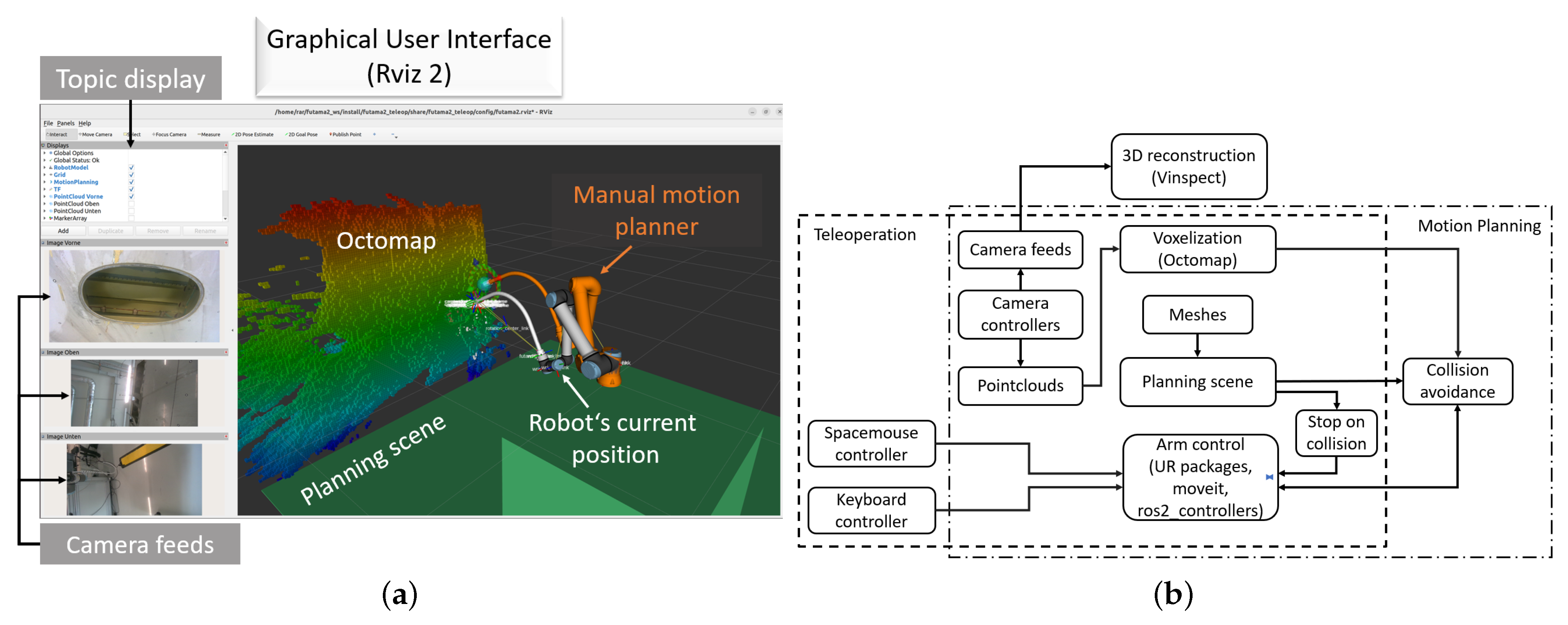
For visualizing the system state, ROS Visualization 2 (RViz 2) [
57] is used as the Graphical User Interface (GUI) due to its seamless integration and clear 3D scene display. Additional plugins, as depicted in
Figure 5a, are integrated to improve the visualization of inspection data.
The system can be configured for simulation or real hardware. In simulation mode, a virtual environment with predefined joint positions and nodes facilitates user training before conducting real experiments. In the real hardware mode, actual joint states are obtained via an Ethernet connection.
Figure 5b provides a scheme of the main software components and their functions.
3.3.2. Operating Modes and Collision Management
The proposed system operates in two modes: teleoperation and motion planning (MP). In both, the D405 cameras capture high-definition (1280 × 720 × 15) images with auto-exposure. Operators can easily capture these images using a key combination, especially when an region of interest (RoI) reveals a surface defect or similar issue.
The robot must handle potential and occurring collision detection in both modes and obstacle avoidance in MP, as it requires reliable collision-free path generation. The stop on collision in both modes can be managed by hardware and software. In hardware, the robotic arm’s built-in safety system detects impacts above a threshold and shuts off power until manually reset. Virtual collision detection, using the MoveIt2 planning scene [
58], loads static objects (shown as constant green in the GUI in
Figure 5a). If the robot’s model, defined with the Unified Robotics Description Format (URDF) overlaps or is very close to an overlap with a virtual object (existing mesh or the robot itself), velocity commands are disabled, and the user is notified. This virtual detection is useful when the impact threshold is too low to trigger hardware safety.
However, in teleoperation, incremental obstacle avoidance—adapting operator-comm-anded velocities to prevent collisions with newly discovered surfaces—is not yet fully integrated. Currently, it relies exclusively on pre-existing object data, and its implementation requires an additional development phase. In contrast, MP already incorporates this capability by utilizing voxel data from Octomap. This integration was more easily achieved within the pipeline, as reliable collision-free path generation is a built-in feature of MoveIt.
The following sections explain both operating modes.
Teleoperation
The teleoperation mode allows users to manually control the robot for quick, responsive actions. In real scenarios, inspection personnel can operate the robot from a safe distance using the spacemouse and monitor it via the GUI with camera feedback. If the spacemouse is unavailable, a keyboard and mouse can be used, though this could reduce control precision due to limited multi-axis input and less intuitive key combinations. The robot’s movements are commanded using Cartesian coordinates or joint rotations.
Figure 6 illustrates an example of an inspection task managed only with teleoperation. However, learning teleoperation always includes the need for training and skill, as well as the manual effort involved, which can reduce efficiency in large-scale operations. Despite these considerations, teleoperation remains essential for manually controlling the robot as needed.
As outlined in
Section 3.3.2, when a collision is detected due to virtual overlap with a known mesh, the moveit_servo halts the robot’s movement entirely and issues a warning. If a collision is triggered by the arm’s vibration threshold, the arm’s built-in mechanism shuts off locomotion.
Currently, the system does not prevent collisions with newly discovered surfaces voxelized by Octomap, which is a limitation to be addressed in future work. For now, it only reduces speed if a collision with a known mesh or the robot itself is imminent, requiring a manual reset afterward. Ensuring effective response times for this feature depends on properly tuning MoveIt parameters, such as the robot’s maximum velocity. In this work, a maximum speed of 0.1 m/s is considered appropriate.
Motion Planning
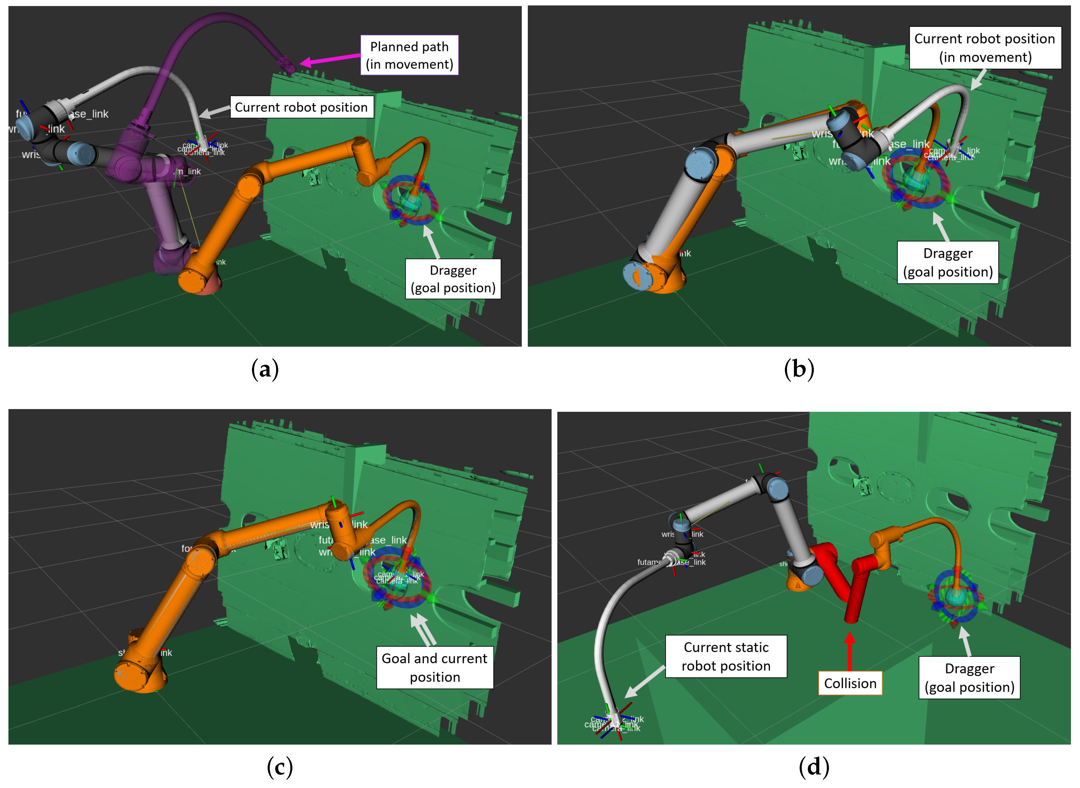
There are two sub-modes of this operating mode: the manual, and the automatic MP. The first one involves setting goals manually in RViz 2 and executing plans using a MoveIt 2 plugin. The internal process, which is not handled by the user, starts by configuring the robot model through the import of physical parameters and kinematic data from a URDF file, including the creation of a MoveIt 2 configuration package with controllers and sensors.
Next, the planning scene is set up in RViz 2 to represent the robot’s workspace and static obstacles. In a simulation environment (
Figure 7), the AFT is included as a known object in the green planning scene. In a real-world environment, the wing is treated as an unknown object, with Octomap used to detect new surfaces and enable collision avoidance as already shown in
Figure 5a.
The target
poses or waypoints are specified by the user using the interactive marker in the GUI. The robot plans the path using the Kinematics and Dynamics Library (KDL) and the Open Motion Planning Library (OMPL). Successful plans are shown (purple motion in
Figure 7a), while failures result in a timeout error requiring manual repositioning. If the pose is valid, pressing the execution button initiates the robot’s movement along the planned path (
Figure 7b) until the goal is reached (
Figure 7c). Collision prevention before path generation is also integrated into the planning scene, highlighting potential collisions in red and preventing initial motion to avoid damage (
Figure 7d). This feature is also active when addressing unknown objects in the scene, not only for loaded meshes (
Figure 5a).
MP also involves selecting an appropriate algorithm from MoveIt 2, such as Rapidly Exploring Random Tree (RRT) or Probabilistic Roadmap (PRM) to calculate a collision-free path considering the robot’s kinematics, joint limits, known meshes and new objects (voxels from Octomap) in the scene. MoveIt 2 interfaces with the robot’s controllers to follow the planned trajectory, with safety checks ensuring the path avoids obstacles and operational limits to avoid singularities. By following these steps in mock or real hardware, users can effectively perform manual MP.
The second version, the automatic MP, is a fully automated mode of the manual MP, capable of utilizing predefined poses for the move_group. It considers the same configurations in MoveIt 2 as the manual version, such as switching between different controllers (Cartesian, constrained joint-based trajectories, etc.). This allows the user to avoid pressing the “plan & execute” button every time the robot needs to move to the next position. This flexibility is particularly useful as it enables quick execution of complex tasks and further reduces human interaction during the inspection. However, since the operator has less time to react in this mode, it is recommended to enable it only after numerous successful tests with the manual MP mode.
3.3.3. Visual Inspection
During the inspection process, the system not only records camera images but also creates a continuously updated 3D reconstruction of the explored areas of the object, which is displayed to the worker for real-time feedback on inspection progress. Although the aim is not to perform surface defect assessment through this reconstruction—since that would require sub-millimeter resolution—this feature is essential for ensuring complete coverage, as any missed areas create holes in the mesh. Full coverage is crucial, as defects can only be detected by the user if the robot has inspected their locations. The reconstruction utilizes the Truncated Signed Distance Function (TSDF) integration [
59] to combine depth images from the three cameras into a volumetric and textured mesh.
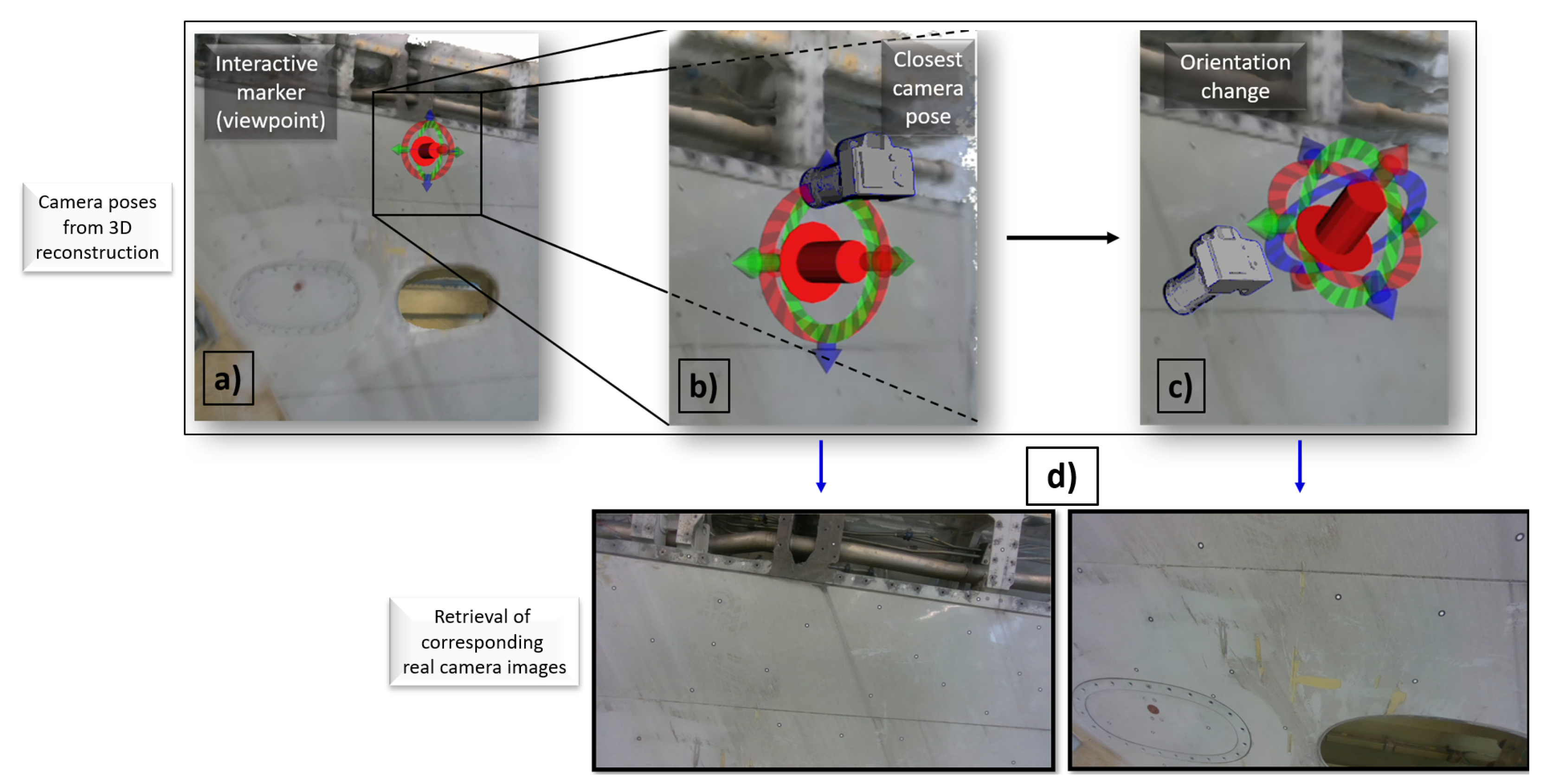
A visual inspection cannot rely solely on a reconstructed mesh, as the algorithm may not display all defects clearly. Therefore, the reconstruction is just used for orientation while the worker reviews the original camera images. The user can move a six DoF interactive marker in RViz 2 to select the desired camera pose. The software then retrieves the images taken closest to this pose. This allows the users to view images in a geometric order instead of the typical chronological order, aiming to facilitate the detection of defects.
Figure 8 depicts a series of images that show how moving an interactive marker in front of a partially reconstructed wing can retrieve images not only based on the translation but different orientations as well, which can be a crucial aspect in inspection processes. This method can be used during the ongoing inspection, speeding up the inspection process and enabling digital transparency.
All this functionality is integrated into a software package called
Vinspect, designed for a wide range of manual and automated robotic inspection tasks [
54].
Vinspect, short for “visualized inspection”, supports various types of inspection data, including sparse measurements (e.g., recorded with ultrasonic sensors) and dense measurements (e.g., recorded with cameras). Key features include the following:
Live integration of multiple inspection processes in a single visualizer
Displaying measurements on the reference object to allow coverage mapping
Intuitive GUI to retrieve original inspection values/data
Save or load previously gathered inspection data to pause or resume an inspection process
Although used with ROS 2 in this work, Vinspect is implemented as a C++ library with Python bindings, allowing integration into various applications and visualizers.
4. Experimental Evaluation
To demonstrate that the proposed robotic system can perform visual inspections in the intended environment, the experiment followed similar steps as shown in
Figure 6. These steps involved utilizing both operating modes during the following phases:
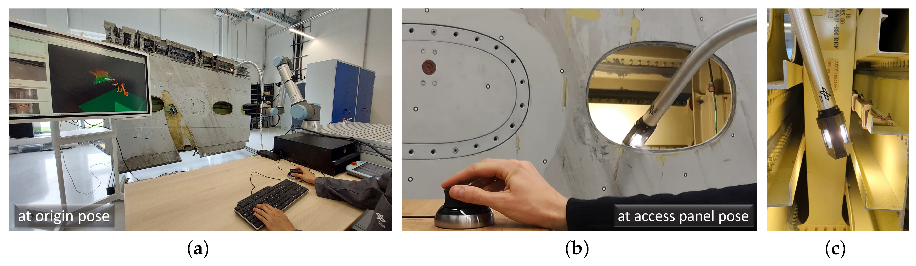
Approaching from the origin pose to the access panel pose.
Navigating through the fuel tank until reaching the tank’s deepest boundary.
Exiting the environment back to the access panel pose.
Returning to the origin pose.
It is important to note that the first inspection was conducted by an operator already familiar with the system. The second inspection was performed by two Human-Computer Interaction (HCI) experts from the department. Its aim was to provide a preliminary evaluation of the overall user experience based on their feedback. This experiment was initially set up using mock hardware as a simulation tool to minimize risks and improve safety. Afterward, it transitioned to the actual use case, which was conducted without any mesh data of the wing to create a more realistic scenario. A quantitative assessment—including factors, such as execution times, sample sizes, user backgrounds, and psychological elements—is beyond the scope of this work.
4.1. Initial Inspection by Trained Operator
In Step 1, performing teleoperation and motion planning (MP) to move the robot from the origin to the access panel was considered a smooth and straightforward task, with minimal risk of collisions. The user could effectively control the robot by visualizing the digital representation in RViz 2, aiding in orientation. MP, whether manual or automated, delivered superior results in open areas compared to teleoperation. By dragging the six DoF marker (manual) or using predefined poses (automatic), trajectories consistently reached the access panel poses in every instance. While teleoperation is often preferred for quicker results, MP excels in handling distant poses and multiple goals with millimeter precision, making it well-suited for this application. MP notably reduced cognitive load, streamlined execution steps, and enhanced safety by effectively avoiding obstacles in open spaces, including both pre-known meshes and newly discovered objects, such as boxes. In this mode, planning solutions were generated and executed in under 10 s, with a maximum speed of 0.3 m/s, which was found to be an appropriate limit for the robot’s motion in this step. Additionally, MP improved user comfort by allowing the operator to concentrate on higher-level tasks.
In Step 2, moving the robot inside the AFT to reach the tank’s deepest boundary significantly changed the situation. In teleoperation, the user could control the robot using slower motions (less than 0.1 m/s) and by combining Cartesian velocity commands with individual joint rotations (maximum 0.1 rad/s) on the wrist_3 joint linked to Eeloscope 2. Although three camera feeds assisted the user with orientation, the probability of collisions increased because the operator could not effectively visualize the robot behind the tank wall. As a result, the operator could not ensure that all walls were adequately covered by the cameras while only relying on RViz 2. Additionally, the camera feed experienced a delay of about 30 ms on the GUI, making quick movements inside the tank difficult to execute without compromising safety. Despite these challenges, careful teleoperation enabled the user to navigate the robot in the tank without major issues. However, the absence of incremental obstacle avoidance in teleoperation required the operator to stand and approach the tank during inspection to prevent potential collisions, making this scenario somewhat unrealistic. In addition, MP encountered a major issue: MoveIt 2 failed to generate plans within the inner area of the fuel tank. As the robot moved deeper into the tank, the likelihood of collisions increased and the plan generation rate decreased. Therefore, the inverse kinematics could not solve the path generation for navigating this confined space with MP. It is speculated that the planning package still cannot evaluate all possible paths to the target. As the path becomes more constrained by side walls, it becomes increasingly difficult for the inverse kinematics to determine the optimal route that minimizes effort while avoiding collisions. These parameters in MoveIt require further tuning and investigation. Consequently, only teleoperation was feasible inside the tank, which still allowed for successful visual inspection data collection.
4.2. Results on Visual Inspection and 3D Reconstruction
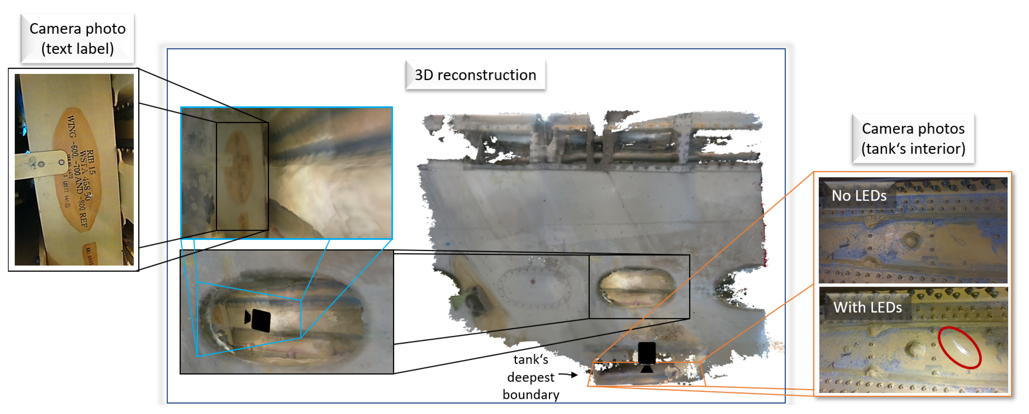
Visual inspection involved not only monitoring the robot’s information on the screen but also capturing images of areas of interest. At the tank’s deepest boundary (bottom-right side in
Figure 9), the user took two photos under different lighting conditions during the operation. In the top-right camera photo, where the environment is nearly dark, the camera’s auto-exposure is adjusted to maintain clarity. In contrast, the bottom-right picture, taken with additional lighting, reveals a scratch defect that becomes visible to the operator when the LEDs are activated, demonstrating that auto-exposure alone is insufficient for immediate defect detection. This confirms that the integrated extra lighting can significantly enhance defect assessment.
To demonstrate the recordability of the navigated pathway, joint states and perception data were recorded in a rosbag [
60]. This tool logs sensor data, control commands, and other ROS 2 topics, enabling users to replay experiments for detailed reviews. The depth data were used to generate a 3D reconstruction (center image of
Figure 9) with the Vinspect package. While the mesh is rough, it provides enough detail for orientation and shows inspected versus uninspected areas, ensuring complete coverage. High-quality camera images are available for defect assessment, though the reconstruction lacks surface accuracy, making fine details, such as text (top-left image of
Figure 9), readable only in photos.
This demonstrates that 3D reconstruction is not enough for details, but in combination with photo capturing, the system allows the user to obtain more relevant information about the inspected workspace. After taking the pictures, the user teleoperated the robot to exit the environment and return to the access panel pose (Step 3). Finally, in Step 4, using MP, the robot safely left the environment and reached the origin position, giving a total time of 6 min for the whole operation.
The presented approach can also be applied to various other areas of visual inspection. It is also not limited to robotic applications but can also be performed with a handheld device. The only requirement is that the pose of the camera is known when an image is taken. This can be achieved with the forward kinematics of the robot. In a handheld device, e.g., visual and IMU-based odometry can be used as well as external tracking systems.
4.3. Preliminary Evaluation by Two HCI Experts
Although a user study was not the primary focus of this work, two HCI specialists from the department were involved in a repeated experiment and were interviewed to collect preliminary results.
During teleoperation, the users found the robot easy to navigate as long as Eeloscope 2 was fully visible outside the AFT and the GUI was accessible on a nearby screen. However, it was remarked that operating the robot inside the AFT increased cognitive stress due to the lack of incremental collision avoidance and the non-real-time rate of the image feeds.
During manual MP, the “plan and execute” button on the MoveIt 2 plugin was effective and satisfying for users, as it immediately displayed the results of an action. The use of the spacemouse buttons for changing operating modes was initially challenging to understand, but after a few minutes of training, it gradually became easier. Although using the mock hardware in RViz 2 was useful for the training process, it remains too technical for inexperienced users and is better suited for developers. The 3D reconstruction, along with image retrieval and the recorded rosbag, was considered valuable for data visualization. Overall, it was discussed that, while there are many areas for improvement, the project is in a promising development phase, as it already addresses some of the challenges and the system integration gaps mentioned in
Section 1.2.
5. Discussion and Future Work
The results outlined in the previous section, based on the trained user’s experience and preliminary evaluation by two HCI experts, suggest that the prototype holds promise for intuitive robotic inspection. However, additional user studies are necessary to comprehensively evaluate its effectiveness.
The current system’s reliance on effective obstacle avoidance highlights its limitation, as motion planning (MP) in confined spaces is still underdeveloped. In addition, further advancements in incremental obstacle avoidance in teleoperation are crucial for broader deployment. Teleoperation relies solely on preloaded meshes, while MP already uses voxelized objects via Octomap. Thin and deformable structures, like cables or straps, may be only detected when visible to cameras, posing safety risks. Adding distance sensors to Eeloscope 2 and the robotic arm, along with incremental obstacle avoidance, could dynamically update the planning scene and enhance safety. This requires computing distances between the robot’s URDF and Octomap voxels and adjusting the user’s commanded speed proportionally along each axis. While conceptually simple, implementation demands precise tuning, particularly given the limited clearance within the fuel tank.
While the current system provides basic feedback about the robot’s status, it limits the user’s ability to maintain situational awareness. The HCI experts suggested adding responsive features, such as real-time pop-up warnings, sound alerts, and LEDs with varying colors, to improve user engagement. Incorporating these elements into a more intuitive and accessible graphical user interface (GUI) is crucial for enhancing operational efficiency and the overall user experience.
To further enhance the operation with the six DoF mouse, ongoing development with newer devices with more button options is being pursued.
The mechanical design of the system, although modular, encounters challenges in achieving sufficient clearance for navigating restricted pathways. The miniaturization of components, inspired by flexible mechanisms, such as the X125© by OC Robotics [
22], could enhance performance in confined spaces. However, implementing such modifications is expected to be costly and complex. Unlike proprietary systems like the X125, which are likely expensive and inaccessible for many institutions, our approach emphasizes the use of standardized robotic arms and modular end-effectors, such as Eeloscope 2. This modularity is anticipated to provide cost savings in the future by streamlining integration through incremental development steps. Nonetheless, these benefits require further validation in diverse real-world scenarios.
The current inspection framework is also limited by its optimization for a single access panel. For more complex use cases, such as inspections requiring multiple access points, integrating a mobile platform with enhanced locomotion capabilities would be necessary.
Furthermore, the system’s effectiveness in detecting defects is constrained under varying lighting conditions, which can obscure surface scratches or other damage. Advanced imaging techniques, such as reflectance transformation imaging [
61], offer potential solutions to improve defect visibility and accuracy.
A significant challenge lies in the documentation and categorization of detected defects. Implementing a taxonomy similar to that outlined in [
7], alongside guidelines for documentation based on Digital Imaging and Communication in Nondestructive Evaluation (DICONDE) could ensure standardized and effective data management. Initial steps in this direction should adhere to the general implementation requirements outlined in the E2339 document [
62].
Further studies on efficiency and key performance indicators, such as inspection thoroughness, are expected to follow the implementation of the proposed enhancements. These investigations will enable direct comparisons with traditional inspection methods and provide a clearer quantification of the system’s benefits.
From a certification perspective, the system must meet explosion protection and temperature range standards to operate safely in volatile environments like kerosene-filled tanks. Compliance with standards such as DIN 60079 [
63] involves selecting suitable electrical components and robust casing materials. High-strength steels or metal alloys [
64] fulfill these requirements, while corrosion-resistant thermoplastics offer a lightweight alternative in corrosive environments [
25]. Balancing safety, durability, and cost remains a technical challenge requiring collaborative efforts.
6. Conclusions
This research focuses on fundamental visual inspection functions for MRO, using AFTs as the primary case study. It evaluates current technologies and lays the groundwork for open-source tools by demonstrating the effectiveness of modular robotic system which prioritizes simplicity and scalability.
Effective teleoperation within the AFT using a six DoF mouse was successfully demonstrated, enhancing user comfort through a GUI integrated within a decentralized framework.
The motion planning (MP) reduced cognitive load by managing collisions through obstacle avoidance, allowing the human operator to focus on higher-level tasks. Additionally, the system proved effective for visualization, monitoring, image acquisition, and 3D reconstruction to aid in potential defect assessment in the future.
Despite these advancements, challenges remain, particularly in reachable collision-free path planning within confined spaces for MP and incremental obstacle avoidance for teleoperation. Further development and parameter tuning are essential to ensure safe navigation within the AFT.
In a preliminary evaluation, two HCI experts expressed overall satisfaction with the system. They noted that while the features were initially challenging to manage, they became intuitive and easy to understand over time, demonstrating one of the main contributions of this work: making small, achievable development steps. However, significant technical improvements, as discussed in
Section 4.3 and
Section 5, are still necessary to enable further validations.
Nonetheless, the proposed approach of this work is expected to result in a more ergonomic solution by utilizing intuitive tools. This can significantly reduce the development time and resources for other research institutions through reproducible methods and scalable functionalities. Improvements are currently being implemented in the system, and other visual inspection use cases are being explored for a wider range of applications.
As another contribution of this work, all system documentation and designs referenced in this paper are available in the project’s public GitHub repository [
53].
Author Contributions
Conceptualization, A.R.O., F.H. and J.H.; methodology, A.R.O., M.B. and F.H.; software, A.R.O., M.B. and L.C.; validation, A.R.O. and M.B.; formal analysis, A.R.O. and M.B.; investigation, A.R.O.; resources, R.R.; data curation, A.R.O., M.B. and L.C.; writing—original draft preparation, A.R.O.; writing—review and editing, A.R.O., M.B, F.H., J.H., L.C. and R.R.; visualization, A.R.O. and M.B.; supervision, R.R. and G.W.; project administration, A.R.O. All authors have read and agreed to the published version of the manuscript.
Funding
This research received no external funding.
Institutional Review Board Statement
Not applicable.
Informed Consent Statement
Not applicable.
Data Availability Statement
The data presented in this study are available on request from the corresponding author.
Acknowledgments
We thank the ROS community for their indirect contributions through some public package releases used in this project. We also appreciate the valuable feedback from Rahel Schmied-Kowarzik and Thore Keser. This work stems from the ‘Fuel Tank Maintenance (FuTaMa) 2’ project at the DLR Institute of Maintenance, Repair, and Overhaul.
Conflicts of Interest
The authors declare no conflicts of interest. Since there was no external funding, there are no additional matters to report.
Abbreviations
The following abbreviations (utilized more than once) are used in this manuscript:
| AFT | Aircraft Fuel Tank |
| AMM | Aircraft Maintenance Manual |
| DICONDE | Digital Imaging and Communication in Nondestructive Evaluation |
| DIN | German Institute of Standardization |
| DoF | degrees of freedom |
| DT | Design Thinking |
| GUI | Graphical User Interface |
| HCI | Human-Computer Interaction |
| LEDs | Light-Emitting Diodes |
| MP | motion planning |
| MPD | Maintenance Planning Document |
| MRO | Maintenance, Repair and Overhaul |
| NDT | Non-Destructive Testing |
| PPE | personal protective equipment |
| RoI | region of onterest |
| ROS 2 | Robot Operating System 2 |
| RViz 2 | ROS Visualization 2 |
| URDF | Unified Robotics Description Format |
References
- Airbus A320 Maintenance Planning Document (MPD). 2018. Available online: https://portail-navigabilite.online/espace_inspecteurs/uploads/mpda320v1_r47_i00.pdf (accessed on 2 June 2024).
- Heilemann, F.; Dadashi, A.; Wicke, K. Eeloscope—Towards a Novel Endoscopic System Enabling Digital Aircraft Fuel Tank Maintenance. Aerospace 2021, 8, 136. [Google Scholar] [CrossRef]
- Dhoot, M.K.; Fan, I.S.; Skaf, Z. Review of Robotic Systems for Aircraft Inspection. SSRN Electron. J. 2020. [Google Scholar] [CrossRef]
- Dhoot, M.K.; Fan, I.S.; Avdelidis, N. Requirements for Designing a Robotic System for Aircraft Wing Fuel Tank Inspection. J. Aerosp. Technol. Manag. 2020, 12, 45–67. [Google Scholar] [CrossRef]
- Dhoot, M.K.; Fan, I.S. Design and Development of a Mobile Robotic System for Aircraft Wing Fuel Tank Inspection. Sae Int. J. Adv. Curr. Pract. Mobil. 2022, 4, 1126–1137. [Google Scholar] [CrossRef]
- European Union Aviation Safety Agency (EASA). Certification Specifications for Large Aeroplanes (CS-25); European Union Aviation Safety Agency: Cologne, Germany, 2022. [Google Scholar]
- Aust, J.; Pons, D. Taxonomy of Gas Turbine Blade Defects. Aerospace 2019, 6, 58. [Google Scholar] [CrossRef]
- Guochen, N.; Wang, J.; Xu, K. Model Analysis for a Continuum Aircraft Fuel Tank Inspection Robot Based on the Rzeppa Universal Joint. Adv. Mech. Eng. 2018, 10, 1687814018778229. [Google Scholar] [CrossRef]
- Joint Base McGuire-Dix-Lakehurst. Airmen Repair KC-10 Extender Fuel Tanks. 2017. Available online: https://www.jbmdl.jb.mil/News/Article-Display/Article/1143955/airmen-repair-kc-10-extender-fuel-tanks/ (accessed on 17 July 2024).
- Modelon. Aircraft Fuel Systems Design: Validate for Safety. 2023. Available online: https://modelon.com/blog/aircraft-fuel-systems-design-validate-for-safety/ (accessed on 17 July 2024).
- The Boeing Company. Aircraft Maintenance Manual Boeing 737 Documentation. WTRUIB 2011-2024. Available online: https://wtruib.ru/boeing_737/amm/ (accessed on 24 July 2024).
- Wolfsafety. American Airlines Fuel Tank Maintenance. Available online: https://www.wolfsafety.com/resources/case-studies/american-airlines-fuel-tank-maintenance (accessed on 20 July 2024).
- Moussa, N.; Devarakonda, V. Analysis of Fuel Tank Explosion Aboard Airplanes. J. Aerosp. Eng. 2019, 32, 04019013. [Google Scholar]
- Lufthansa Technik. Fuel Tank Sanitization Breaks the Vicious Circle of Microbial Fuel System Contamination. 2024. Available online: https://www.lufthansa-technik.com/en/fuel-tank-sanitization-breaks-the-vicious-circle-of-microbial-fuel-system-contamination-e79646943cdd57c7 (accessed on 9 July 2024).
- Federal Aviation Administration. Lessons Learned Library. 2024. Available online: https://www.faa.gov/lessons_learned/accidents/lessons_learned_library (accessed on 20 July 2024).
- Flight Safety Services. Accident Report: TH/2001-03-03. 2021. Available online: https://www.fss.aero/accident-reports/dvdfiles/TH/2001-03-03-TH.pdf (accessed on 22 July 2024).
- Kim, H.G.; Kim, S.; An, S.H.; Ha, B.G.; Kim, Y.S. Validation of the Structural Integrity of an Aircraft External Fuel Tank through a Structural Test under Flight-Load Conditions. Proc. Inst. Mech. Eng. Part G J. Aerosp. Eng. 2023, 237, 2112–2124. [Google Scholar] [CrossRef]
- U.S. Air Force. Robotic Arm Tool Poised to Save Costly Inspection Time. 2017. Available online: https://www.af.mil/News/Article-Display/Article/1088209/robotic-arm-tool-poised-to-save-costly-inspection-time/ (accessed on 4 June 2024).
- Su, H.; Hou, X.; Zhang, X.; Qi, W.; Cai, S.; Xiong, X.; Guo, J. Pneumatic Soft Robots: Challenges and Benefits. Actuators 2022, 11, 92. [Google Scholar] [CrossRef]
- Post, M.A.; Yan, X.T.; Letier, P. Modularity for the Future in Space Robotics: A Review. Acta Astronaut. 2021, 189, 530–547. [Google Scholar] [CrossRef]
- Iqbal, J.; Tahir, A.M.; Ul Islam, R.; Riaz-un-Nabi. Robotics for Nuclear Power Plants—Challenges and Future Perspectives. In Proceedings of the 2012 2nd International Conference on Applied Robotics for the Power Industry (CARPI), Zurich, Switzerland, 11–13 September 2012; pp. 151–156. [Google Scholar] [CrossRef]
- OCRobotics. OC Robotics—Series II, X125 Snake-Arm Robot for UCL. 2015. Available online: https://www.youtube.com/watch?v=I4M6fYEyAIY (accessed on 31 July 2024).
- Gaina, M.G. Dangerous Entry into the Aircraft Fuel Tank—Introduction of Mobil Robot. Incas Bull. 2019, 11, 97–110. [Google Scholar] [CrossRef]
- Guardian S Robot. Robots Guide. Available online: https://robotsguide.com/robots/guardians (accessed on 31 July 2024).
- Christensen, L.; Fischer, N.; Kroffke, W.; Lemburg, J.; Ahlers, R. Cost-Effective Autonomous Robots for Ballast Water Tank Inspection. 2008. Available online: https://www.researchgate.net/publication/233508332_Cost-Effective_Autonomous_Robots_for_Ballast_Water_Tank_Inspection (accessed on 31 July 2024).
- Eelume. Eelume M-Series. 2024. Available online: https://www.eelume.com/eelume-m-series (accessed on 31 July 2024).
- Buckingham, R.; Chitrakaran, V.; Conkie, R.; Ferguson, G.; Graham, A.; Lichon, M.; Parry, N.; Pollard, F.; Kayani, A.; Redman, M.; et al. Snake-Arm Robots: A New Approach to Aircraft Assembly. SAE Tech. Pap. 2007. [Google Scholar] [CrossRef]
- NewsHour, P. Japan Probe into Melted Fukushima Reactor Finished with Robot. 2015. Available online: https://www.pbs.org/newshour/world/japan-probe-melted-fukushima-reactor-finished-robot (accessed on 1 August 2024).
- Was Messen MRL-Werte? 2015. Available online: http://live-twi.cloud.contensis.com/locations/deutschland/was-wir-tun/haeufig-gestellte-fragen/was-messen-mrl-werte.aspx (accessed on 14 July 2024).
- Technology Readiness Levels—NASA. Available online: https://www.nasa.gov/directorates/somd/space-communications-navigation-program/technology-readiness-levels/ (accessed on 3 August 2024).
- Panzino, C. Robotic Snake Can Save Airmen 29 Hours of Aircraft Inspection Time. 2017. Available online: https://www.airforcetimes.com/news/your-air-force/2017/09/20/robotic-snake-can-save-airmen-29-hours-of-aircraft-inspection-time/ (accessed on 17 June 2024).
- Guochen, N.; Kailu, X. Path Planning Based on Q-learning and Three-Segment Method for Aircraft Fuel Tank Inspection Robot. Filomat 2018, 32, 1797–1807. [Google Scholar] [CrossRef]
- Harvard Business School Online. Design Thinking Examples. 2020. Available online: https://online.hbs.edu/blog/post/design-thinking-examples (accessed on 16 August 2024).
- Tramonti, M.; Dochshanov, A.M.; Zhumabayeva, A.S. Design Thinking as an Auxiliary Tool for Educational Robotics Classes. Appl. Sci. 2023, 13, 858. [Google Scholar] [CrossRef]
- Xu, K.; Simaan, N. Actuation Compensation for Flexible Surgical Snake-like Robots with Redundant Remote Actuation. In Proceedings of the 2006 IEEE International Conference on Robotics and Automation, ICRA, Orlando, FL, USA, 15–19 May 2006; pp. 4148–4154. [Google Scholar] [CrossRef]
- The Decision Lab. Functional Fixedness. 2021. Available online: https://thedecisionlab.com/biases/functional-fixedness (accessed on 4 August 2024).
- VectorStock. Flying Plane Bottom View Engraving Vector. 2024. Available online: https://www.vectorstock.com/royalty-free-vector/flying-plane-bottom-view-engraving-vector-36153969 (accessed on 3 June 2024).
- Alamy. Aeroplane Side View Vector. 2024. Available online: https://www.alamy.com/stock-photo/aeroplane-side-view-vector.html?page=3 (accessed on 3 June 2024).
- Schmidt, L.; Hegenberg, J.; Cramar, L. User Studies on Teleoperation of Robots for Plant Inspection. Ind. Robot. Int. J. 2014, 41, 6–14. [Google Scholar] [CrossRef]
- Luk, B.; Liu, K.; Collie, A.; Cooke, D.; Chen, S. Tele-operated Climbing and Mobile Service Robots for Remote Inspection and Maintenance in Nuclear Industry. Ind. Robot. Int. J. 2006, 33, 194–204. [Google Scholar] [CrossRef]
- Kazanzides, P.; Vagvolgyi, B.P.; Pryor, W.; Deguet, A.; Leonard, S.; Whitcomb, L.L. Teleoperation and Visualization Interfaces for Remote Intervention in Space. Front. Robot. AI 2021, 8, 747917. [Google Scholar] [CrossRef] [PubMed]
- Universal Robots. UR10 Collaborative Robot. 2024. Available online: https://www.universal-robots.com/de/produkte/ur10-roboter/ (accessed on 3 June 2024).
- Universal Robots. Universal Robots GitHub Repository. 2024. Available online: https://github.com/UniversalRobots (accessed on 14 July 2024).
- DIN EN ISO 10218-1:2016-06; Robots and Robotic Devices—Safety Requirements for Industrial Robots—Part 1: Robots. ISO: Geneva, Switzerland, 2016. Available online: https://www.dinmedia.de/de/norm/din-en-iso-10218-1/136373717 (accessed on 20 July 2024).
- Intel. Intel RealSense Depth Camera D405. Available online: https://www.intelrealsense.com/depth-camera-d405/ (accessed on 13 July 2024).
- ThinkLucid. Phoenix 32 MP IMX265 Camera. 2024. Available online: https://thinklucid.com/de/product/phoenix-32-mp-imx265/?srsltid=AfmBOoruQGK6yjMjAtqEmMJNEQmUtbVURJQDw6H_SFLGZkivve7I9wHN (accessed on 4 June 2024).
- RealSense, I. Creating Real-Time Digital Twins with Intel RealSense Depth Cameras. 2023. Available online: https://www.intelrealsense.com/creating-real-time-digital-twins-with-intel-realsense-depth-cameras/ (accessed on 9 July 2024).
- Robot Operating System (ROS). ROS Installation Documentation. Available online: https://docs.ros.org/en/rolling/Installation.html (accessed on 10 July 2024).
- Intel RealSense. Realsense-Ros. 2024. Available online: https://github.com/IntelRealSense/realsense-ros (accessed on 4 July 2024).
- Welcome to the Ros2_control Documentation!—ROS2_Control: Rolling Jul 2024 Documentation. Available online: https://control.ros.org/rolling/index.html (accessed on 15 June 2024).
- Introducing MoveIt Servo in ROS 2 | MoveIt. Available online: https://moveit.ros.org/moveit/ros2/servo/jog/2020/09/09/moveit2-servo.html (accessed on 20 July 2024).
- OctoMap. OctoMap: A Probabilistic 3D Mapping Framework. Available online: https://octomap.github.io/ (accessed on 10 July 2024).
- DLR-MO. FuTaMa2. 2024. Available online: https://github.com/DLR-MO/FuTaMa2 (accessed on 15 August 2024).
- DLR-MO/Vinspect: Vinspect (Short for “Visualized Inspection”) Provides a Multiple Functionalities That Support an Inspection Process. Available online: https://github.com/DLR-MO/vinspect (accessed on 1 August 2024).
- 3Dconnexion. New 3D Mouse from Market Leader 3Dconnexion: SpaceMouse Compact Provides Intuitive 3D Navigation and Comfortable Reviewing of 3D Designs. 2024. Available online: https://3dconnexion.com/uk/press-room/ (accessed on 2 July 2024).
- ROS Package: Spacenav. 2024. Available online: https://index.ros.org/p/spacenav/ (accessed on 28 July 2024).
- Robot Operating System (ROS). Recording and Playing Back Data. 2024. Available online: https://docs.ros.org/en/rolling/Tutorials/Intermediate/RViz/RViz-User-Guide/RViz-User-Guide.html (accessed on 1 July 2024).
- Planning Scene—MoveIt Documentation: Rolling Documentation. Available online: https://moveit.picknik.ai/main/doc/examples/planning_scene/planning_scene_tutorial.html (accessed on 21 June 2024).
- Curless, B.; Levoy, M. A Volumetric Method for Building Complex Models from Range Images. 1996. Available online: https://graphics.stanford.edu/papers/volrange/volrange.pdf (accessed on 16 August 2024).
- Recording and Playing Back Data—ROS 2 Documentation: Rolling Documentation. Available online: https://docs.ros.org/en/rolling/Tutorials/Beginner-CLI-Tools/Recording-And-Playing-Back-Data/Recording-And-Playing-Back-Data.html (accessed on 1 July 2024).
- Khawaja, M.A.; George, S.; Marzani, F.; Hardeberg, J.Y.; Mansouri, A. An Interactive Method for Adaptive Acquisition in Reflectance Transformation Imaging for Cultural Heritage. In Proceedings of the 2023 IEEE/CVF International Conference on Computer Vision Workshops (ICCVW), Paris, France, 2–3 October 2023; pp. 1690–1698. [Google Scholar] [CrossRef]
- Standard Guide for Digital Imaging and Communication in Nondestructive Evaluation (DICONDE). 2021. Available online: https://www.astm.org/e2339-21.html (accessed on 5 August 2024).
- Verlag, V. DIN EN 60079-0:2014-06; Explosive Atmospheres—Part 0: Equipment—General Requirements. 2014. Available online: https://www.vde-verlag.de/normen/0100214/din-en-60079-0-vde-0170-1-2014-06.html (accessed on 15 July 2024).
- Zhai, G.; Zhang, W.; Hu, W.; Ji, Z. Coal Mine Rescue Robots Based on Binocular Vision: A Review of the State of the Art. IEEE Access 2020, 8, 130561–130575. [Google Scholar] [CrossRef]
| Disclaimer/Publisher’s Note: The statements, opinions and data contained in all publications are solely those of the individual author(s) and contributor(s) and not of MDPI and/or the editor(s). MDPI and/or the editor(s) disclaim responsibility for any injury to people or property resulting from any ideas, methods, instructions or products referred to in the content. |
© 2025 by the authors. Licensee MDPI, Basel, Switzerland. This article is an open access article distributed under the terms and conditions of the Creative Commons Attribution (CC BY) license (https://creativecommons.org/licenses/by/4.0/).


 ,
, 

