Article

Investigation of the Thermal Vibration Behavior of an Orthogonal Woven Composite Nozzle Based on RVE Analysis

1
College of Material Science and Technology, Nanjing University of Aeronautics and Astronautics, Nanjing 211106, China
2
State Key Laboratory of Mechanics and Control of Mechanical Structures, Nanjing University of Aeronautics and Astronautics, Nanjing 210016, China
3
Inner Mongolia Institute of Dynamical Machinery, Hohhot 010000, China
*
Author to whom correspondence should be addressed.
Aerospace 2025, 12(2), 157; https://doi.org/10.3390/aerospace12020157
Submission received: 30 December 2024 / Revised: 16 February 2025 / Accepted: 17 February 2025 / Published: 18 February 2025
(This article belongs to the Section Aeronautics)

Abstract

:
Carbon fiber-reinforced epoxy composites, known for their high specific stiffness, specific strength, and toughness are one of the primary materials used for composite nozzles in aerospace industries. The high temperature vibration behaviors of the composite nozzles, especially those that withstand internal pressures, are key to affecting their dynamic response and even failure during the service. This study investigates the changes in frequencies and the vibrational modes of the carbon fiber reinforced epoxy nozzles, focusing on a three-dimensional (3D) orthogonal woven composite, with high internal temperatures from 25 °C to 300 °C and non-uniform internal pressures, up to 5.4 MPa. By considering the temperature-sensitive parameters, including Young’s modulus, thermal conductivity, and thermal expansion coefficients, which are derived from a self-built representative volume element (RVE), the intrinsic frequencies and vibrational modes in composite nozzles were examined. Findings reveal that 2 nodal diameter (ND) and 3ND modes are influenced by E x x and E y y while bending and torsion modes are predominantly affected by shear modulus. Temperature and internal pressure exhibit opposite effects on the modal frequencies. When the inner wall temperature rises from 25 °C to 300 °C, 2ND and 3ND frequencies decrease by an average of 30.39%, while bending and torsion frequencies decline by an average of 54.80%, primarily attributed to the decline modulus. Modal shifts were observed at ~150 °C, where the bending mode shifts to the 1st-order mode. More importantly, introducing non-uniform internal pressures induces the increase in nozzle stiffening in the xy-plane, leading to an apparent increase in the average 2ND and 3ND frequencies by 17.89% and 7.96%, while negligible changes in the bending and torsional frequencies. The temperature where the modal shifts were reduced to ~50 °C. The research performed in this work offers crucial insights for assessing the vibration life and safety design of hypersonic flight vehicles exposed to high-temperature thermal vibrations.

1. Introduction

During high-speed flight, the nozzle at the rear of the aircraft engine is subjected to prolonged exposure to high-temperature exhaust flows, creating a high-gradient thermal field and inducing severe thermal and unsteady aerodynamic loads. This leads to significant challenges, such as low-cycle fatigue and high-stress failures in localized structural regions, with these issues intricately linked to the modal parameters of the nozzle [1,2]. Therefore, a comprehensive understanding of the modal frequencies and vibration modes of the nozzle under such complex environments is crucial for both the preliminary design and the in-service performance evaluation of the nozzle.
Numerous scholars have conducted extensive research on predicting the modal parameters of the nozzle during service. Garelli et al. [3] employed a fluid–structure interaction (FSI) approach based on a staggered algorithm to investigate the effects of lateral loads on the modal frequencies of rocket engines during ignition. Wang et al. [4] explored the deformation effects of transient lateral loads under coupled FSI fields on the nozzle by conducting transient aeroelastic analysis for 2.8 s after the main engine of a space shuttle ignited, obtaining predicted lateral load peaks and dominant frequencies consistent with actual results. Zhang et al. [5] studied the impact of wall material properties and thickness on the aeroelastic behavior of rocket nozzles during startup, revealing that when the material modulus dropped by 90%, the frequencies of the bending mode and 2ND and 3ND modes decreased by about 63%. Additionally, some researchers have used experimental modal analysis to acquire the modal parameters of the nozzle. Yan et al. [6] used 3D scanning laser Doppler vibrometry (SLDV) to obtain the first six modes and modal frequencies of a thin-walled nozzle, noting a maximum frequency error of 3.94% between computational modal analysis and experimental modal analysis results. Eitner et al. [7] estimated the modal parameters of small rocket nozzles using blind source separation (BSS), finding that the obtained characteristic frequencies differed by no more than 0.1% from results derived using CP (complexity pursuit), SOBI (second-order blind identification), and SSI (stochastic subspace identification), though damping discrepancies reached up to 60%. However, these studies primarily focus on the modal frequencies and vibration modes of the metal nozzle, with minimal attention given to the modal parameters of the composite nozzle.
Carbon fiber-reinforced resin matrix composites possess remarkable advantages such as high specific stiffness, specific strength, and toughness, making them one of the preferred materials for the diffuser section of solid rocket engine nozzles in aerospace applications. However, during service, composite nozzles are subjected to high-temperature and high-pressure loads, which may lead to reductions in material modulus, structural deformation, and internal thermal stresses. These factors not only degrade the load-bearing capacity of the nozzle but also potentially induce severe phenomena such as flutter, highlighting the urgent need for research into the vibration response behavior of composite nozzles under such extreme conditions. Many scholars have conducted high-temperature vibration tests and modal frequency analyses of composite materials [8,9,10]. For instance, Santos Silva et al. [11] used non-contact measurement methods such as DIC and thermal imaging to obtain full-field displacement and temperature data on flat plates under various heating conditions within the temperature range of 25~550 °C, discovering that the sixth mode at room temperature transitioned to the fifth mode after longitudinal heating. Gao et al. [12] established a non-contact system for measuring the thermal vibration behavior of fiber-reinforced silicon carbide in an oxidizing environment at 1600 °C, using fiber Bragg sensors and laser vibrometry to capture the temperature-sensitive behavior of the first three modal frequencies in the time domain. Wu et al. [13] developed a bi-sided infrared heating vibration test system at 1200 °C and conducted both computational and experimental modal analyses on a nickel alloy cantilever plate between 200~1200 °C, with the first three modal frequency errors being less than 6.0% between numerical and experimental results. Gao et al. [14] further investigated the effects of braiding angle on damping and modal frequencies, conducting modal tests on three-dimensional five-directional braided composite cantilever beams with various braiding angles. Pei et al. [15] explored the impact of fiber volume fraction and braiding angle on modal frequencies, using an RVE model to predict the elastic properties of three- and four-dimensional braided composites and comparing the modal test results of cantilever beams to finite element model results, where the average relative error for the first three modal frequencies was 4.19%. Singh et al. [16] studied the free vibration and buckling response of layered and braided composite plates using a new higher-order shear deformation theory, analyzing parameters such as aspect ratio, fiber volume fraction, and braiding angle on the modal frequencies of composite plates. Huang et al. [17] used a multiscale model to investigate the influence of fiber volume fraction and braiding angle on the modal frequencies of three-dimensional braided composites. Dan et al. [18] established an equivalent model for 3D braided composite plates based on the variational asymptotic method, exploring the effects of geometric parameters and layup angles on the bending, buckling, and free vibration characteristics of plain-woven composites. Nevertheless, there is still a lack of research on the vibration characteristics of composite nozzles under high-temperature and high-pressure conditions. The impact of temperature-induced material property changes on the modal parameters of composite remains unclear, and the methods for conducting modal analyses of composite nozzles under such extreme conditions are poorly understood. Therefore, further research into the evolution of modal parameters in composite nozzles under temperature and pressure loads is urgently needed.
Current modal analysis of composite nozzles primarily focuses on structural deformation induced by internal flow field loads, leading to changes in modal frequencies and mode shapes, as well as modal analysis and experimental validation of the nozzle components at room temperature. However, it does not address the decrease in modal frequency caused by the reduction in stiffness of composite nozzle materials due to temperature effects. In this work, the impact of internal flow field loads on the composite nozzle is simplified into a distribution of non-uniform pressure and temperature loads on the inner wall, thereby reducing computational costs. Additionally, compared to the modulus variation obtained from curve fitting and interpolation methods, the modulus obtained from unit cell simulations more accurately reflects the reduction in modulus caused by variations in material component parameters during the heating process. This allows for a more reasonable prediction of the modal parameter changes in the nozzle in the operational environment.
Current modal characterization of composite nozzles predominantly addresses flow-induced structural deformation, resulting in shifts in modal frequencies and mode shapes, alongside room temperature modal analysis and experimental validation of subcomponents. However, existing studies neglect the progressive modal frequency attenuation arising from the thermomechanical degradation of composite nozzle materials. In this study, internal aerodynamic loads are idealized as spatially varying pressure and thermal load distributions across the nozzle’s inner wall surface, significantly improving computational efficiency. Furthermore, micromechanical unit cell simulations provide superior prediction of modulus degradation during thermal exposure compared to empirical curve-fitting approaches, as they explicitly account for constituent-level property variations. This enables accurate prediction of nozzle modal behavior under service conditions.
This study focuses on investigating the influence of temperature-sensitive material properties on the modal parameters of 3D orthogonal woven composites. The RVE model of the 3D orthogonal woven composite was developed to explore the dynamic behavior of composite nozzles under the influence of temperature and internal pressure loads, taking into account the variations in material properties induced by temperature changes. Initially, based on the temperature-sensitive properties of fibers and resin, the RVE model was employed to provide temperature-sensitive material properties for the composite nozzle. Modal analysis was then conducted to determine the modal frequencies and vibration mode of the composite nozzle under non-uniform internal pressure and temperature loads. Finally, the study explores the evolution of modal frequencies and modal shifting phenomena of the composite nozzle under the combined influence of thermal and internal pressure loads.

2. Simulation Model

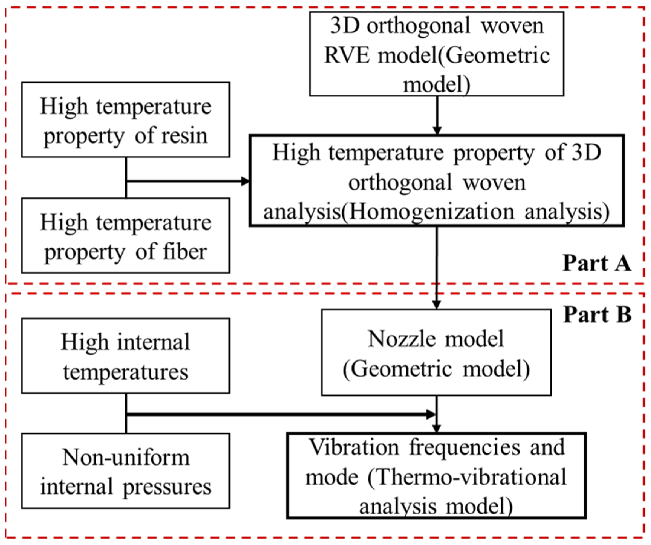
2.1. Thermo-Vibrational Coupling Analysis Process

The FE simulation of this study follows the below framework, as depicted in Figure 1. The entire simulation process is divided into two main parts: Part A concentrates on building an RVE model of the 3D orthogonal woven composite, which provides all required temperature-sensitive material properties for the subsequent Part B. Part B concentrates on building an FE model of the composite nozzle used for analyzing the vibration frequency and modes at the designed temperature and pressure gradients. The detailed FE simulation setup and procedure are provided in the next section.

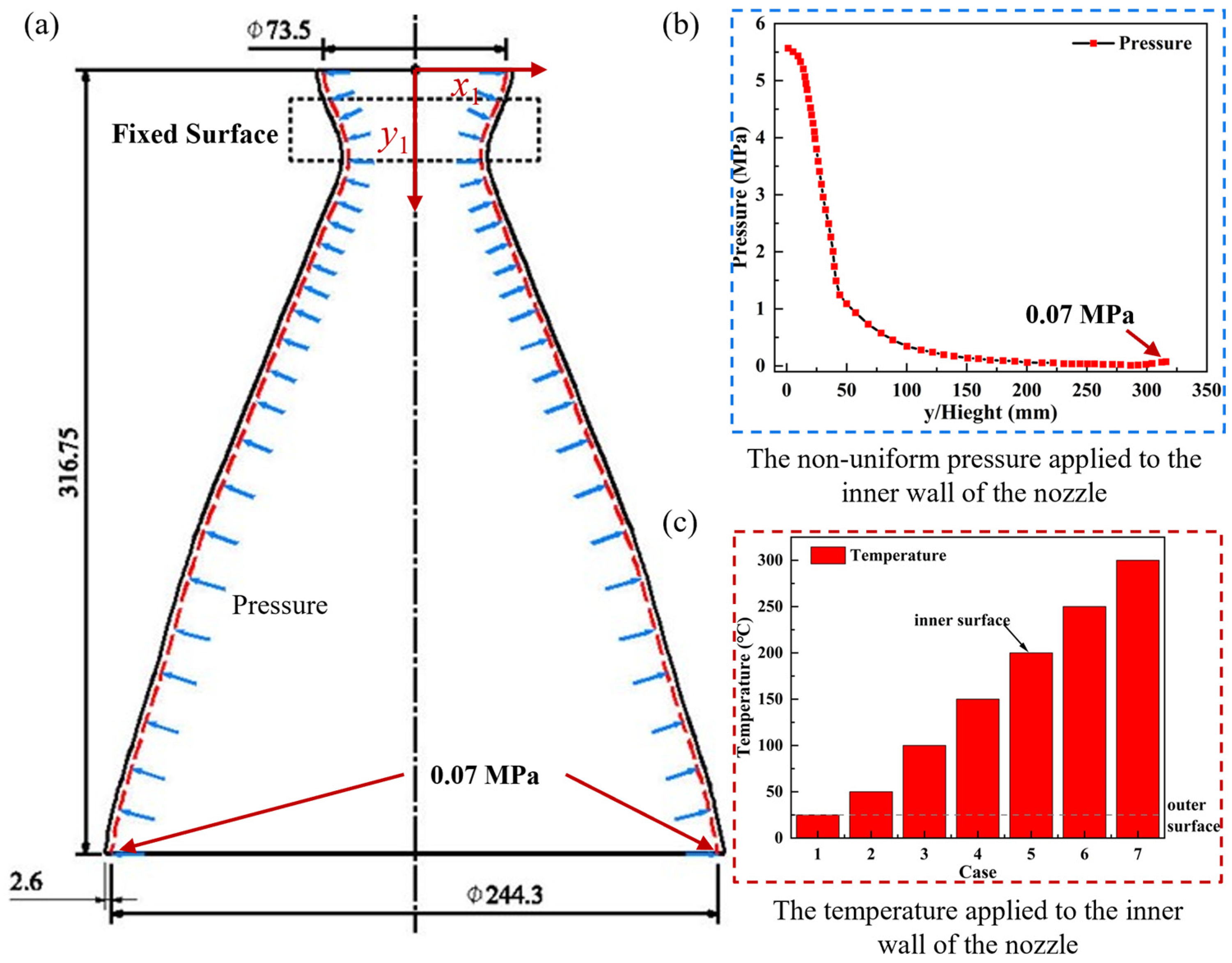
2.2. Thermo-Vibrational Analysis Model of Composite Nozzle

The thermo-vibrational coupling analysis model of the composite nozzle is developed to account for the dynamic behavior of nozzle components under thermal and internal pressure loads while factoring in the temperature-sensitive variation in material properties. Note that the nozzle geometry is taken from a representative model in [3]. In this study, the composite nozzle’s overall height is 316.75 mm, with a small-end diameter of 73.5 mm, a large-end diameter of 244.3 mm, and an expansion ratio of 4.59. Figure 2 displays the geometric dimensions of the composite nozzle model. For the composite nozzle model, the solid187 element in ANSYS/workbench software (version 2022 R12) is used. The model is discretized into 473,109 elements and 795,497 nodes, with a convergence analysis conducted to validate the reliability of the elements. The coordinate origin is set at the center point on the top of the nozzle, as annotated in Figure 2a. Figure 2 illustrates the temperature and pressure distribution of the finite element model applied to the composite nozzle. The load cases applied to the composite nozzle are classified into two categories: (1) temperature only and (2) combined temperature and non-uniform internal pressure load. Category 1 considers varying temperature distributions in the thickness direction, with inner wall temperatures set at 25 °C, 50 °C, 100 °C, 150 °C, 200 °C, 250 °C, and 300 °C while maintaining a constant outer wall temperature of 25 °C. The detailed schemes are presented in Table 1. Category 2 introduces non-uniform internal pressure, where the pressure data of the composite nozzle are derived from the Korea Aerospace Research Institute (KARI), based on flexible oscillating nozzles [19]. Considering the practical application in industrial environments, this study conducts thermal vibration analysis under fixed boundary conditions at the throat region. The throat of the composite nozzle, as annotated in Figure 2a, is fixed in all directions, which is expected to simulate the connections between the composite nozzle and the outer case.

2.3. RVE of 3D Orthogonal Woven Composites

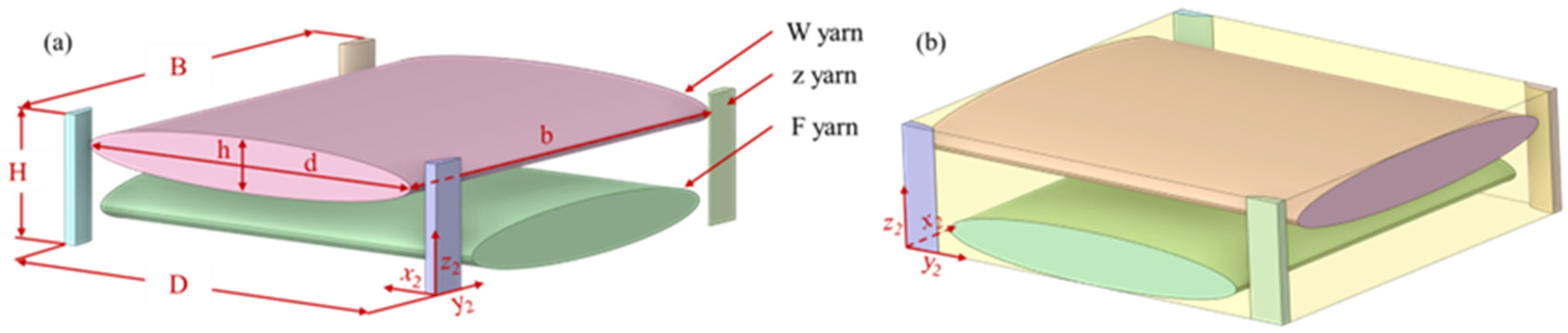
2.3.1. Geometric Model of RVE

This section focused on building the RVE model. The resulting material properties from the RVE model, based on the homogenization theory, are used for further analyzing the vibration performances of the nozzle. The 3D orthogonal woven model investigated in this study consists of warp yarns (W) arranged in a 90° cross-stacked configuration, weft yarns (F), and z-yarn connectors. To accurately capture the typical structure of the woven composite, the yarns in this model are represented with an elliptical cross-section [20]. The RVE model is depicted in Figure 3b. Within this framework, the z 1 axis corresponds to the thickness direction, the y 1 axis aligns with the fabric’s longitudinal direction, and the x 1 axis represents the width direction. The yarn’s thickness is denoted as h , its width as d , and its length as b . The overall dimensions of the RVE models are 5.2 × 5.5 × 1.5 mm3, comprising both fibers and resins, with detailed dimensions of the RVE provided in Table 2. The fiber volume fraction within this RVE model is 55.66%, as represented as V f . While the resin volume fraction is represented as V m .

2.3.2. RVE Simulation

Drawing on the literature micrographs and typical structures [20,21,22], we chose an elliptical cross-section for the woven yarns and defined their geometric dimensions and streamlined spatial distributions per yarn type. Finally, Boolean operations were employed to embed the 3D orthogonal woven yarns into the resin matrix, forming an RVE model. The RVE model uses the solid187 element type in ANSYS software. The model is discretized into a total of 455,941 elements and 698,324 nodes. In macroscopic engineering applications, most fibers and fiber braids are typically treated as transversely isotropic, requiring the consideration of the distinct material properties along the fiber’s longitudinal and transverse directions. Here, the longitudinal direction aligns with the fiber orientation, while the transverse direction is perpendicular to it. Experimental results reported by Dong et al. [23] reveal significant disparities between the thermal conductivity in the fiber’s transverse and longitudinal directions. Similarly, additional studies by Dong et al. [24] demonstrate marked differences in the coefficient of thermal expansion (CTE) between these orientations. Consequently, in this study, the thermal expansion coefficients and thermal conductivities of fibers are approximated by transverse isotropic fittings. The unique manufacturing process of carbon fiber confers high modulus and thermal resistance. However, significant performance changes are typically observed only above 1000 °C [25,26]. Most studies on T700 carbon fiber-reinforced composites indicate that from room temperature to 300 °C, the primary factors influencing material performance are the matrix and the matrix–fiber interface [27,28]. Therefore, this study focuses solely on the decline in resin mechanical properties with rising temperatures.
The property of the resin at different temperatures is considered due to its degradation. Room temperature material properties for fibers and resins, as summarized in Table 3 and Table 4, are extracted from the research by Dong and Pan [23,24,29]. The thermal and material properties of the epoxy at high temperatures are provided in Figure 4 [23,24,29].

3. Results

3.1. Material Properties Change with Temperature

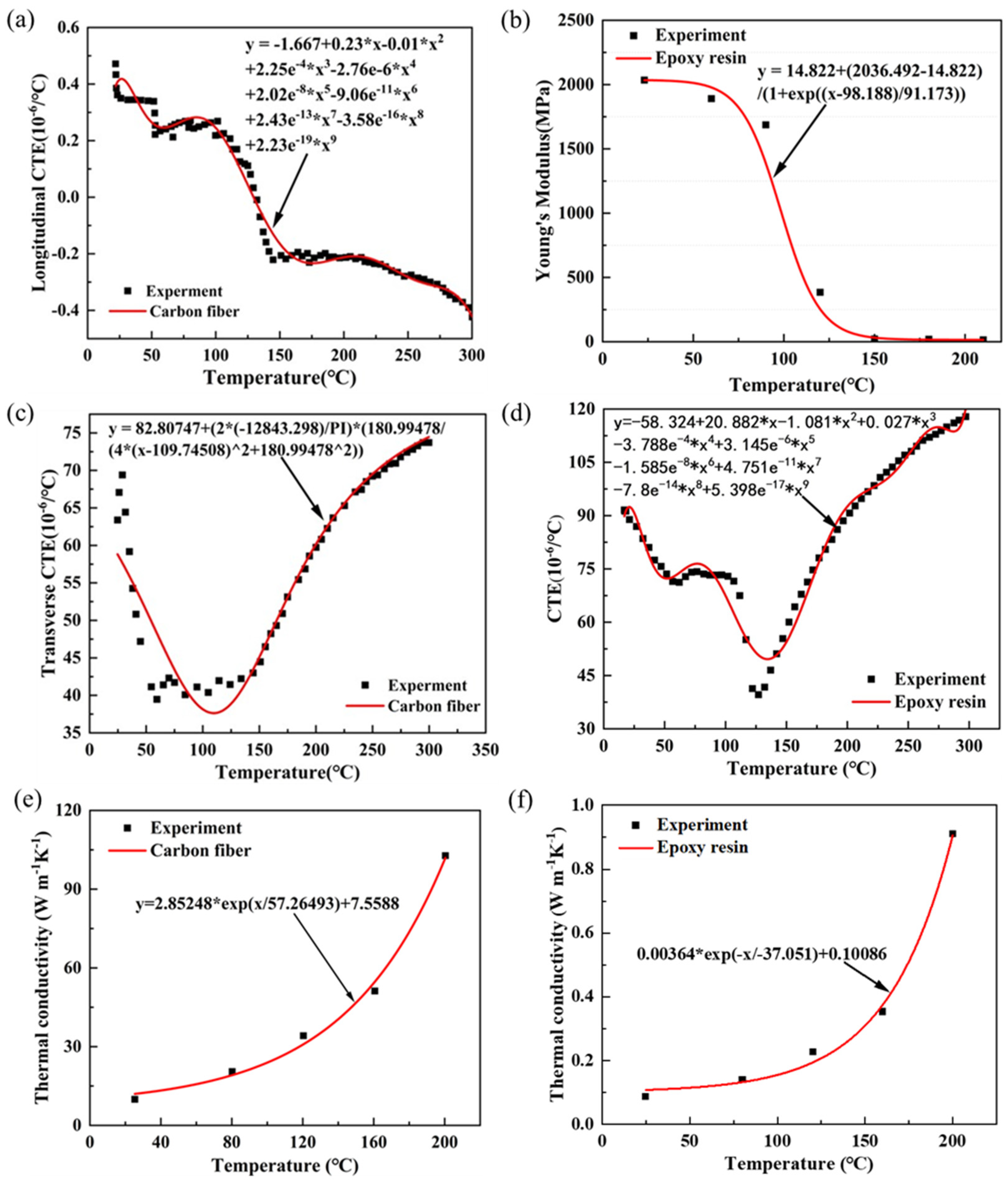
3.1.1. High-Temperature Properties of Fibers and Resins

Figure 4 presents the material properties concerning temperature. The thermal expansion coefficient data for fiber and resin were derived from the work of Dong et al. [24], while the experimental data for the temperature-dependent Young’s modulus of resin came from Pan et al. [29]. Additionally, thermal conductivity data for both fiber and resin were obtained from Dong et al. [23]. The longitudinal thermal expansion coefficient of the fiber generally decreases with rising temperature, but the transverse thermal expansion coefficient initially decreases and then increases, aligning with the trend of epoxy resin. This behavior may be due to the use of experimental data from unidirectional fiber-reinforced epoxy composites. The Young’s modulus of epoxy decreases with temperature and then stabilizes. Similarly, the thermal conductivity of both fiber and resin shows exponential growth with temperature, with fiber increasing more sharply. To unify temperature-sensitive material data and establish the high-temperature RVE model for the 3D orthogonal woven composite, this study applied the Lorentz function to fit the transverse thermal expansion data of carbon fiber, achieving over 99% accuracy. The longitudinal thermal expansion coefficient of the fiber and the thermal expansion coefficient of the epoxy resin were fitted using a polynomial function, reaching a fit of over 96%. Meanwhile, Young’s modulus of the epoxy resin was fitted using a Boltzmann function with over 99% accuracy. Finally, the thermal conductivity of both carbon fiber and epoxy resin was fitted using the expdecl function, achieving over 99% accuracy. The data curves obtained through experimental data fitting demonstrate R2 values exceeding 0.95, which reasonably reflects the variations in material parameters to some extent. These fitted equations will be further applied to subsequent RVE analysis within the design temperature range.

3.1.2. RVE of the 3D Orthogonal Woven Composites at High Temperatures

Figure 5 and Figure 6 illustrate the variation patterns of the high-temperature thermophysical properties of 3D orthogonal woven composites, based on the fitting of the material properties of fibers and resins. The mechanical properties of these composites exhibit transverse isotropy, where the modulus parallel to the fiber directions is similar, while the modulus perpendicular to the fiber directions is lower, approaching that of the epoxy resin. Figure 5a presents the tensile modulus of the 3D orthogonal woven composites obtained from simulations across the temperature range of 25 °C to 300 °C. At room temperature, the modulus E x x and E y y are both 70.87 GPa. As the temperature rises to 300 °C, E x x and E y y decrease to 60.47 GPa, marking a 14.67% reduction in modulus. Notably, 9.29% of this reduction occurs between 90 °C and 120 °C. For E z z , the modulus is 5.91 GPa at room temperature, but it drops dramatically to 0.17 GPa at 300 °C, reflecting a 97.12% loss, with 60.57% of the reduction occurring within the 90 °C to 120 °C range.
Figure 5b shows the shear modulus of the 3D orthogonal wove composites obtained from simulations over the same temperature range. The G x z and G y z modulus are both 1.85 GPa at room temperature. At 300 °C, G x z and G y z decrease to 0.02 GPa, resulting in a 98.92% modulus loss, with 61.08% of this loss occurring between 90 °C and 120 °C. The G x y modulus starts at 3.62 GPa at room temperature and decreases to 0.11 GPa at 300 °C, representing a 96.96% reduction, with 47.79% of the loss occurring between 90 °C and 120 °C. The shear modulus in the xz-and yz-planes is similar to that of the matrix, while in the xy-plane, it is closer to that of the fibers. This behavior may be attributed to the relatively small volume fraction of connecting yarns in the xz-and yz-planes, causing the resin to become the primary load-bearing component when perturbations occur in these planes.
Figure 5c shows the Poisson’s ratios of the 3D orthogonal wove composites obtained from simulations across the temperature range of 25 °C to 300 °C. The Poisson’s ratios v x z and v y z are both 38.2 at room temperature. As the temperature increases to 300 °C, v x z and v y z decrease to 13.16, representing a 65.55% change, with a significant 46.02% change occurring between 120 °C and 150 °C. The Poisson’s ratio v x y is 2.01 at room temperature and decreases to 0.05 by 300 °C, resulting in a 97.51% change, with 54.23% of this change occurring between 120 °C and 150 °C.
The mechanical properties of the fitted RVE models exhibit transverse isotropy and can be analyzed using the rule of mixtures:
σ = σ f V f + σ m V m ,
Here, σ denotes the total stress, σ f represents the stress experienced by the fiber, and σ m corresponds to the stress experienced by the resin. In composites subjected to stresses in the x and y directions, along with perturbations in the xy-plane, the W warp and F weft yarns, due to their significant volume fraction, serve as the primary load carriers. As illustrated in Figure 5b, the significant reduction in the shear modulus of the 3D orthogonal woven composite occurs between 90 °C and 150 °C. Beyond 150 °C, the shear modulus becomes relatively insensitive to temperature, gradually stabilizing. This trend is similar to that of the resin’s shear modulus in Figure 4a. Consequently, the properties of the 3D orthogonal woven composites derived through homogenization theory indicate that the mechanical properties in the x and y directions are primarily influenced by the fibers, whereas the shear modulus is predominantly governed by the resin. Table 5 presents the mechanical properties predicted from the RVE, with deviations of 1.9% for E x x , 17.54% for E y y , and 8.45% for v x y compared to experimental data—results that align well with those obtained by Li et al. [20] using a smooth fabric unit cell model.
Figure 6a illustrates the thermal conductivity of 3D orthogonal woven composites obtained through simulation across the temperature range of 25 °C to 300 °C. The thermal conductivity of these composites shows an exponential increase as the temperature rises. At room temperature, both k x x and k y y have thermal conductivities of 4.53 W/(m∙K). When the temperature reaches 300 °C, the thermal conductivity of k x x and k y y increases to 191.8 W/(m∙K), representing a 130.5% rise between 250 °C and 300 °C. Meanwhile, k z z starts at 0.42 W/(m∙K) at room temperature. As the temperature increases to 300 °C, k z z reaches 34.43 W/(m∙K), reflecting a 198.8% increase during the 250 °C to 300 °C range.
Figure 6b displays the coefficient of thermal expansion for the 3D orthogonal woven composites obtained through simulation across the temperature range of 25 °C to 300 °C. At room temperature, the 3D orthogonal woven composites have coefficients of thermal expansion of α x x = 2.69 × 10⁻⁶/°C and α y y = 3.16 × 10⁻⁶/°C. When the temperature is raised to 300 °C, α x x decreases to 0.34 × 10⁻⁶/°C, and α y y reduces to 0.74 × 10⁻⁶/°C. During this period, α x x experiences an 87.47% reduction in thermal expansion, while α y y experiences a 76.74% reduction, with the most significant reduction (58.8%) occurring between 50 °C and 100 °C. The coefficient of thermal expansion α z z is initially 70.92 × 10⁻⁶/°C at room temperature and decreases to 30.22 × 10⁻⁶/°C at 300 °C, reflecting a 57.39% reduction overall, with a 42.18% reduction observed between 100 °C and 150 °C.

3.2. Modal Analysis of the Nozzle at High Temperature

Figure 7 illustrates the first four modal frequencies with different inner wall temperatures. Overall, the frequency of each mode decreases as the temperature increases. Before the inner wall temperature reaches 100 °C, the frequency changes for each mode remain smooth. However, when the temperature hits 100 °C, a sharp decline in frequency occurs, likely due to the decrease in modulus. At 300 °C, the torsional mode and 3ND mode show the most significant reductions, decreasing by 226.49 Hz and 164.55 Hz, respectively, from their frequencies at 25 °C, with absolute reduction rates of 55.89% and 33.54%. The 2ND mode drops to 146.13 Hz, and the bending mode reduces to 108.24 Hz. The modal frequency is primarily influenced by the stiffness and mass distribution of the structure. From Figure 5, it is evident that in the temperature range of 25 °C to 150 °C, the structure’s modulus decreases overall, a trend consistent with the change in modal frequencies. The initial frequencies are 200.82 Hz for the 2ND mode, 233.89 Hz for the bending mode, and 490.55 Hz for the 3ND mode.
Figure 8 highlights the modal shifting between 150 °C and 200 °C. When the inner wall temperature rises from 150 °C to 200 °C, the first-order 2ND mode and second-order bending mode experience modal shifting. Figure 5 shows that by 150 °C, the modulus of the composite nozzle has nearly reached its lowest point and flattens out, yet the frequency continues to drop. The modal shifting in the first four modes is likely due to the compressive thermal stresses reducing the local stiffness [31].
From the stiffness matrix perspective, the loss in Young’s modulus below 100 °C is much smaller compared to that at higher temperatures, as previously presented in Figure 5a. Additionally, thermal stress at lower temperatures has little effect on structure stiffness, leading to minor intrinsic frequency reductions. However, at 150 °C, Young’s modulus substantially degrades, and thermal stresses start to affect stiffness. This results in the maximum decrease in intrinsic frequencies, coinciding with a 96.96% loss in shear modulus, which is highly sensitive to thermal stress. Bending and torsion modes are likely affected by shear modulus changes primarily, while the 2ND and 3ND modes are likely influenced by E x x and E y y primarily [32]. Beyond 150 °C, the structure’s thermal conductivity increases exponentially, causing a larger temperature difference between the inner and outer wall surfaces, enhancing thermal stresses and further reducing bending and torsional frequencies. The decrease in 2ND and 3ND modal frequencies slows due to smaller losses in E x x and E y y , leading to the bending modes swapping with the 2ND mode after 150 °C.

3.3. Modal Analysis of the Nozzle with Non-Uniform Internal Pressure

Figure 9 illustrates the first four modal frequencies of the composite nozzle obtained with non-uniform internal pressures at different temperatures. When the composite nozzle is subjected to both internal pressure and temperature loads, the 2ND and 3ND modal frequencies show an initial increase followed by a decrease. When the inner wall temperature reaches 300 °C, the torsional mode and 3ND mode experience the largest reductions, decreasing by 227.67 Hz (i.e., 56.26%) and 159.79 Hz (i.e., 31.55%), respectively, compared to that of 25 °C. The 2ND mode drops to 165.93 Hz, and the bending modal frequency decreases to 106.91 Hz. Applying non-uniform internal pressure to the composite nozzle wall changes the initial frequency of the 2ND mode to 217.32 Hz, an 8.22% increase compared to the no-pressure load case, while the initial frequency of the 3ND mode rises to 506.48 Hz, a 3.25% increase. Additionally, in the 25 °C to 150 °C range, the 2ND mode frequency increases by 7.45 Hz, a 3.43% relative increase compared to the bending mode, leading to an earlier modal shifting. Figure 10 shows the modal shift of the 2ND and bending modes in the 25 °C to 50 °C interval. When the inner wall temperature increases from 25 °C to 50 °C, the first-order 2ND mode switches places with the second-order bending mode.
A comparison between the cases with and without non-uniform wall pressure reveals that the bending and torsional modal frequencies are largely unaffected by non-uniform pressure, while the 2ND and 3ND modal frequencies increase by 17.89% and 7.96%, respectively. The frequency rise is likely due to the enhanced stiffness in the xz-plane induced by the non-uniform pressure perpendicular to the inner nozzle wall. However, as temperature increases, the decline in material modulus and the growing influence of thermal stress become dominant, leading to an overall downward trend in the first four modal frequencies. At 300 °C, the 2ND modal frequency rises by 19.8 Hz compared to that without internal pressure, as shown in Figure 9, while the 3ND modal frequency increases by 20.69 Hz.

4. Discussion

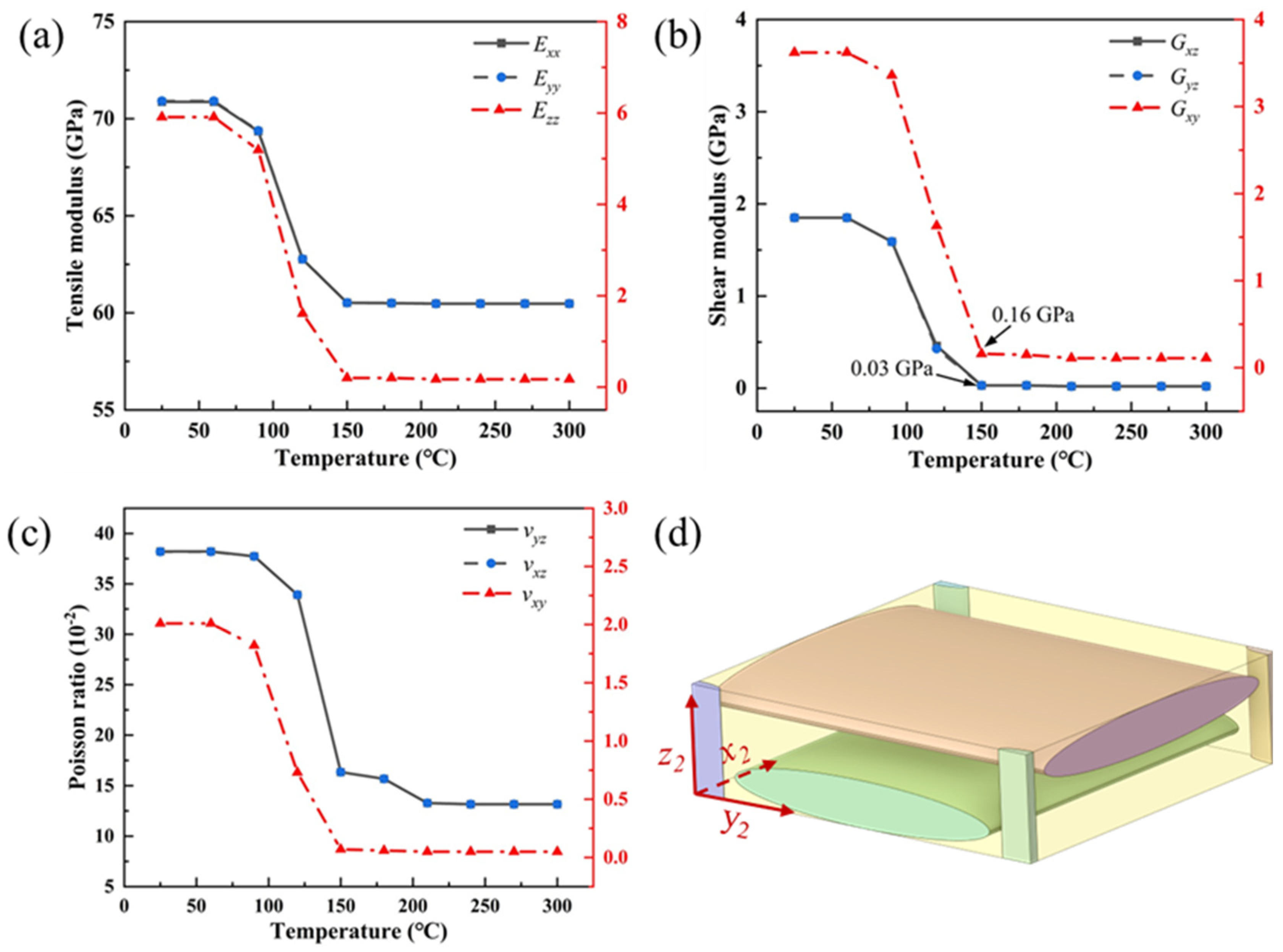
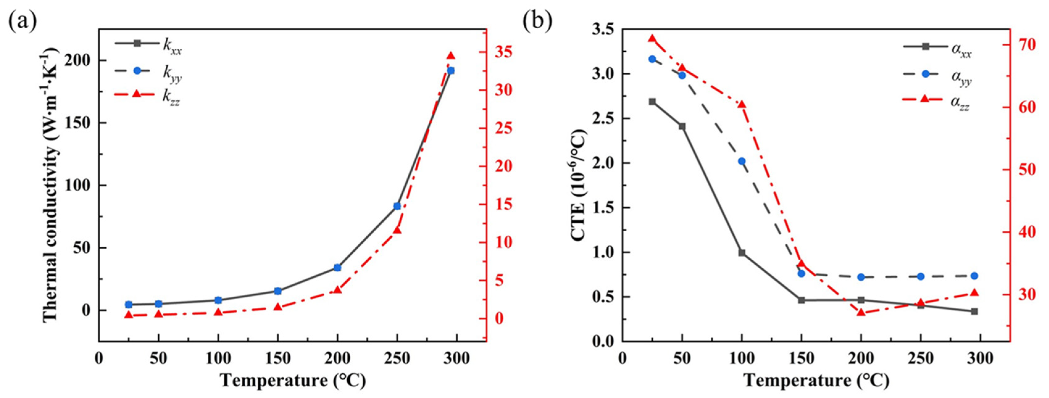
4.1. Material Properties from RVE Analysis at High Temperature

The primary variation interval of high-temperature mechanical properties, as predicted by the RVE simulations of 3D orthogonal woven composites, lies within the temperature range of 50 °C to 150 °C. Beyond 150 °C, the mechanical properties of the composites exhibit minimal change, which is similar to the behavior observed in epoxy matrix composites under thermal conditions, as reported by Pan et al. [29]. This similarity might arise from both studies, primarily considering the temperature-sensitive behavior of the matrix material. In contrast, Pan et al. [29] employed the rule of mixtures to estimate the material properties of 3D orthogonal woven composites between 23 °C and 210 °C, finding that the shear modulus decreased by 99.3% at 210 °C-a discrepancy from the current study, potentially attributable to differences in fiber bundle arrangement and resin matrix volume fraction. The high-temperature thermal conductivity derived from the RVE for 3D orthogonal woven composites shows a gradual increase with temperature, aligning closely with the thermal conductivity trends of woven composites observed by Dong et al. [23]. The thermal conductivities along the k x x and k y y directions initially exceed those along the k z z direction, yet all exhibit a nonlinear increase with rising temperature, possibly due to phonon-mediated heat transfer in the epoxy matrix composites, which is highly sensitive to temperature changes [33].
In this study, the thermal expansion coefficients of carbon fibers were evaluated over the temperature range of 25 °C to 300 °C, with α x x and α y y changing by 2.35 × 10⁻⁶/°C and 2.43 × 10⁻⁶/°C, respectively, and α z z by 40.7 × 10⁻⁶/°C, as Figure 4. This behavior is likely because the CTEs of carbon fibers in the longitudinal and transverse directions remain relatively stable from room temperature up to 300 °C, whereas the CTE in the z-direction is primarily influenced by the resin. The z-direction CTE shows a decreasing trend followed by an increase, consistent with the results from Dong et al. [24], who predicted the CTE in the fiber’s vertical direction using a mesoscale finite element model of unidirectional carbon fiber-reinforced epoxy matrix composites. The trend is similar to pure cured epoxy resin but with a considerably lower value, which can be attributed to the lower CTE of the fiber in the transverse direction.

4.2. Vibration Behavior of the Composite Nozzle

As the temperature of the composite nozzle’s inner wall gradually increases, the first four modal frequencies of the composite nozzle also decrease gradually. Initially, the changes in these modal frequencies are gentle, as observed from the material’s modulus curve; during this stage, the structure maintains a relatively high modulus and is subjected to low thermal stress. When the temperature reaches 100 °C, the modal frequencies begin to decrease significantly. This corresponds with the material’s modulus changing with temperature: from 90 °C to 150 °C, E x x and E y y decrease from 69.35 GPa and 69.38 GPa to 60.52 GPa, while E z z decreases from 5.19 GPa to 1.61 GPa, as shown in Figure 5a. When the temperature further increases beyond 150 °C, the decline in material modulus begins to stabilize. Simultaneously, the temperature difference between the inner and outer walls of the composite nozzle increases, causing uneven expansion of the nozzle components and generating thermal stress. This results in a further decrease in the first four modal frequencies of the composite nozzle. Notably, when the temperature reaches 250 °C, the decline in the first four modal frequencies of the composite nozzle significantly slows down. This is likely due to the frequency changes being primarily influenced by the coupling between modulus and thermal stress, with the major temperature range for significant variations in modulus and thermal expansion coefficients being 100 °C to 200 °C in this study. If the components are subjected to higher temperatures, their modal frequencies and mode shapes will exhibit more complex behavior due to factors such as material thermal degradation. And the behavior will be a focus of our future research.
Upon introducing nonuniform pressure loads, as the inner wall temperature of the nozzle rises, the 2ND and 3ND modal frequencies first increase and then decrease, while the bending and torsional modal frequencies remain consistent with the case without non-uniform pressure. At 50 °C, the 2ND modal frequency is 235.59 Hz, an increase of 34.36 Hz compared to the case without non-uniform pressure. The frequency rise may be due to the enhanced stiffness in the xz-plane caused by the nonuniform pressure at the inner wall. As the temperature continues to increase, the first four modal frequencies of the composite nozzle show a downward trend, although the rate of decline in the 2ND modal frequency slows, likely due to the combined effects of non-uniform pressure and thermal stress.

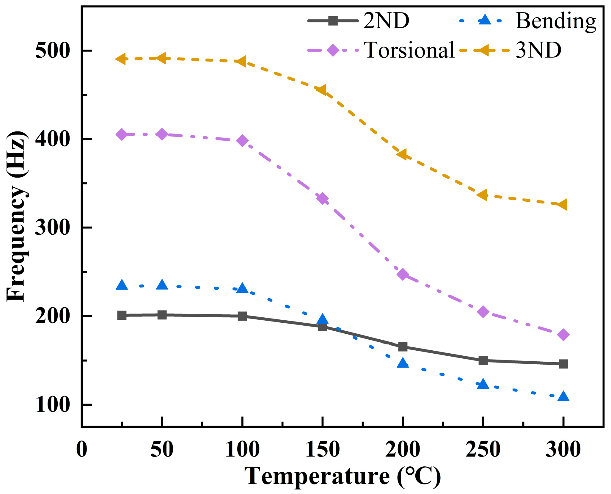
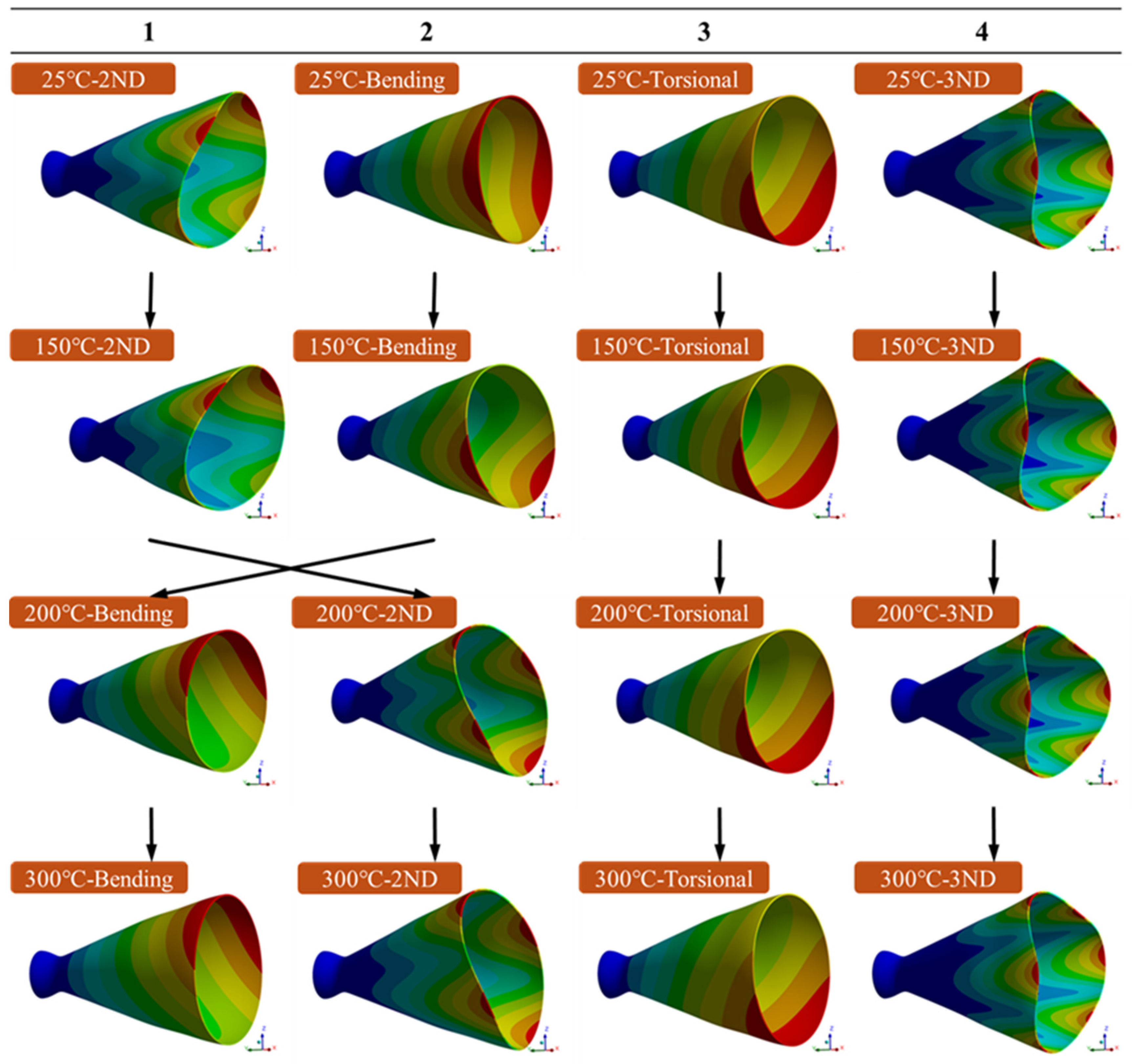
4.3. Vibration Frequency and Modal Changes at High Temperatures

This study investigates the evolution of the first four modal frequencies of the composite nozzle subjected to a non-uniform temperature distribution across the wall thickness, considering the variation of its material properties with temperature. Initially, the modal frequencies of the nozzle decrease as the inner wall temperature rises. Additionally, higher temperatures may cause the epoxy groups in the resin to break, triggering the rupture of the cross-linked structure, releasing gases that create voids and bubbles, and significantly reducing the mechanical properties of the material. The behavior is similar to the first three modal frequencies of carbon fiber-reinforced silicon carbide materials observed by Y. Gao et al. [12] under high-temperature oxidation conditions, where frequencies initially decrease with temperature increases and stabilize as they approach 400 °C. As the inner wall temperature of the nozzle continues to rise, the change in material modulus stabilizes. At this point, the temperature difference between the inner and outer wall surfaces of the composite nozzle increases. Additionally, the significant difference between αxx and αzz in the 3D orthogonal composite causes uneven material expansion, resulting in thermal stress. This leads to further reductions in the first four modal frequencies of the composite nozzle. Notably, between 150 °C and 200 °C, the 2ND and bending modes experience modal shifting.
In 2003, D.J. Mead et al. [31] examined the impact of in-plane pressure caused by non-uniform thermal strain on the modal frequencies and bending modes of an ideal free rectangular Kirchhoff plate. It demonstrated that the order of specific vibrational modes changes with increased excitation frequency, a phenomenon known as modal shifting. Similarly, in 2019, A.C. Santos Silva et al. [11] observed a modal shift in flat plate members under different heating methods, where the fifth and sixth modal vibration modes shifted order as the temperature increased. The authors attributed these changes in modal frequencies to the effects of inhomogeneous spatial temperature distribution, which alters the plate’s shape as it attempts to reach a steady state, thereby influencing the energy required to excite each mode shape.

4.4. Vibration Frequency and Modal Changes with Non-Uniform Internal Pressures

The modal parameters of the composite nozzle are influenced by the stiffness and mass distribution of the structure. In this study, the first four modes include the 2ND, bending, torsional, and 3ND modes, which are very similar to those observed in 2017 by Song Yan et al. [6] at room temperature, where the first three modes were 2ND and bending modes, with the fourth and fifth being 3ND and torsional modes, respectively. Likewise, in 2018, S. Kim et al. [34] performed a modal analysis of nozzle members using steel–copper–steel laminated anisotropic materials and reported similar mode shapes, where the first and second modes were 2ND, the third mode was 3ND, and the fourth was torsional. Additionally, the results from T.S. Wang et al. [4] in 2014, based on transient fluid–structure coupling analysis, showed a similar pattern with the first and second modes as 2ND, the third and fourth as bending modes, and the fifth and sixth as 3ND modes. The differences in the sequence of these modes may be due to variations in material properties and boundary conditions.
When the composite nozzle is subjected to pressure loads perpendicular to the inner wall, the modal shifting that originally occurred between 150 °C and 200 °C, as Figure 8, is advanced to the 25 °C to 50 °C range, as previous Figure 10, likely due to the increased stiffness of the xz-plane from the non-uniform internal pressure. After introducing non-uniform internal pressure, the modal frequencies of the 2ND and 3ND modes, which are sensitive to E x x and E y y , increased by an average of 17.89% and 7.96%, respectively, while the bending and torsional modes remained unaffected. As the inner wall temperature rises, under the combined influence of thermal stress and non-uniform internal pressure, the 2ND and bending modes undergo modal shifting. The temperature where the modal shifts were reduced to ~50 °C.

5. Conclusions

Based on the temperature-sensitive material properties, thermal conductivity, and coefficient of thermal expansion, the thermo-structural dynamic response of the composite nozzle under different loads is predicted using thermo-vibrational coupling analysis. This analysis reveals the advancement of the modal shifting temperature from 150 °C to 50 °C, along with more intricate modal shifting phenomena.
  • The rise in temperature of the composite nozzle‘s inner wall leads to material modulus loss and thermal stress intensification, causing a reduction in the frequencies of the first four mode orders. Under the dominant influence of thermal stress, the torsional mode, which is sensitive to shear modulus loss, exhibits a greater frequency drop. When the inner wall temperature reaches 300 °C, the 2ND and 3ND modes decrease by an average of 30.39%, while the bending and torsional modes drop by an average of 54.80%. The torsional modal frequency, in particular, drops from 405.26 Hz to 178.77 Hz, reflecting a 55.89% reduction compared to the frequency at 25 °C.
  • The introduction of non-uniform internal pressure enhances the stiffness of the composite nozzle in the xz-plane, causing the frequencies of the 2ND and 3ND modes to increase by an average of 17.89% and 7.96%, respectively. However, under the dominant influence of thermal stress, the overall frequency of the first four mode orders still exhibits a downward trend. As the inner wall temperature of the nozzle rises to 300 °C, and the torsional modal frequency drops from 404.68 Hz to 177.01 Hz, reflecting a 56.26% decrease relative to its frequency at 25 °C. This trend aligns with the case without internal pressure. Meanwhile, the average frequency drop of the 2ND and 3ND modes is 27.6%.
  • An inner wall temperature of 150 °C leads to a modal interchange between the bending mode and the 2ND mode due to the decreased shear modulus (i.e., decreased by 96.96% from 25 °C to 150 °C). Introducing non-uniform internal pressure loads on the inner wall of the composite nozzle reduces the modal shifting temperature to approximately 50 °C. It is likely because the combined effect of rising temperatures and decreasing modulus lowers the composite nozzle’s frequency, while non-uniform internal pressure increases the 2ND and 3ND modal frequencies.
  • The RVE of the 3D orthogonal woven composite, constructed based on homogenization theory, shows that the material properties and shear modulus in the z-direction are primarily influenced by the performance of the epoxy resin. At a nozzle inner wall temperature of 300 °C, the 3D orthogonal woven composite experiences a loss of 98.27% in shear modulus and 97.12% in E z z , consistent with the thermal response pattern of pure epoxy resin. Meanwhile, the properties in the x and y directions of the composite are predominantly governed by carbon fiber.

Author Contributions

Conceptualization, L.W., X.L. and J.Z.; methodology, L.W., X.L., Y.C., Y.J. and X.H.; formal analysis, L.W., X.L., Y.C., Y.J. and J.Z.; investigation, C.F. and W.S.; data curation, W.S. and X.H.; writing—original draft preparation, L.W. and J.Z.; writing—review and editing, L.W., X.L., Y.J. and J.Z.; supervision, C.F. and J.Z.; supervision, C.F. and J.Z. All authors have read and agreed to the published version of the manuscript.

Funding

This research received no external funding.

Data Availability Statement

All data supporting this study are available in the article.

Conflicts of Interest

The authors declare no conflicts of interest.

Nomenclature

E 11 f Young’s modulus of fiber in direction 1, GPa E 11 m Young’s modulus of resin in direction 1, GPa
E 22 f , E 33 f Young’s modulus of fiber in direction 2 and 3, GPa E 22 m , E 33 m Young’s modulus of resin in direction 2 and 3, GPa
G 12 f , G 13 f Shear modulus of fiber in 12-plane and 23-plane, GPa G 12 m , G 13 m Shear modulus of resin in 12-plane and 23-plane, GPa
G 23 f Shear modulus of fiber in 23-plane, GPa G 23 m Shear modulus of resin in 23-plane, GPa
v 12 f , v 13 f Poisson ratio of fiber in 12-plane and 13-plane v 12 m , v 13 m Poisson ratio of resin in 12-plane and 13-plane
v 23 f Poisson ratio of fiber in 23-plane v 23 m Poisson ratio of resin in 23-plane
α 1 f CTE of fiber in direction 1, 10−6/℃ α 1 m CTE of resin in direction 1, 10−6/℃
α 2 f , α 3 f CTE of fiber in direction 2 and direction 3, 10−6/℃ α 2 m , α 3 m CTE of resin in direction 2 and direction 3, 10−6/℃
ρ f Density   of   fiber ,   kg m−3 ρ m Density   of   resin ,   kg m−3
k f Thermal   conductivity   parallel   to   the   fiber   direction ,   W (m−1 k−1) k m Thermal   conductivity   of   resin ,   W (m−1 k−1)
k f Thermal   conductivity   perpendicular   to   the   fiber   direction ,   W (m−1 k−1) k m Thermal   conductivity   of   resin ,   W (m−1 k−1)
E x x Young’s modulus of 3D orthogonal woven composite in direction x, GPa k x x Thermal   conductivity   of   3 D   orthogonal   woven   composite   in   direction   x ,   W (m−1 k−1)
E y y Young’s modulus of 3D orthogonal woven composite in direction y, GPa k y y Thermal   conductivity   of   3 D   orthogonal   woven   composite   in   direction   y ,   W (m−1 k−1)
E z z Young’s modulus of 3D orthogonal woven composite in direction z, GPa k z z Thermal   conductivity   of   3 D   orthogonal   woven   composite   in   direction   z ,   W (m−1 k−1)
G x y Shear modulus of 3D orthogonal woven composite in xy-plane, GPa α x x CTE of 3D orthogonal woven composite in direction x, 10−6/℃
G x z Shear modulus of 3D orthogonal woven composite in xz-plane, GPa α y y CTE of 3D orthogonal woven composite in direction y, 10−6/℃
G y z Shear modulus of 3D orthogonal woven composite in yz-plane, GPa α z z CTE of 3D orthogonal woven composite in direction z, 10−6/℃
v x y Poisson ratio of 3D orthogonal woven composite in xy-plane
v x z Poisson ratio of 3D orthogonal woven composite in xz-plane
v y z Poisson ratio of 3D orthogonal woven composite in yz-plane

References

  1. Gu, X.; Dong, L.; Li, T.; Yang, W. A Study on Influence of Flapping Dynamic Characteristics on Vibration Control of Active Rotor with Trailing-Edge Flaps. Aerospace 2023, 10, 776. [Google Scholar] [CrossRef]
  2. Xu, F.; Li, H.; Zhang, D. A Study on Dynamic Characteristics of Thin-Walled Cylindrical Cavities with a Large Aspect Ratio. Aerospace 2022, 9, 174. [Google Scholar] [CrossRef]
  3. Garelli, L.; Paz, R.R.; Storti, M.A. Fluid–Structure Interaction Study of the Start-up of a Rocket Engine Nozzle. Comput. Fluids 2010, 39, 1208–1218. [Google Scholar] [CrossRef]
  4. Wang, T.-S.; Zhao, X.; Zhang, S.; Chen, Y.-S. Development of an Aeroelastic Modeling Capability for Transient Nozzle Flow Analysis. J. Propul. Power 2014, 30, 1692–1700. [Google Scholar] [CrossRef]
  5. Zhang, J.A.; Shotorban, B.; Zhang, S. Numerical Experiment of Aeroelastic Stability for a Rocket Nozzle. J. Aerosp. Eng. 2017, 30, 04017041. [Google Scholar] [CrossRef]
  6. Yan, S.; Li, B.; Li, F.; Li, B. Finite Element Model Updating of Liquid Rocket Engine Nozzle Based on Modal Test Results Obtained from 3-D SLDV Technique. Aerosp. Sci. Technol. 2017, 69, 412–418. [Google Scholar] [CrossRef]
  7. Eitner, M.A.; Sirohi, J.; Tinney, C.E. Modal parameter estimation of a reduced-scale rocket nozzle using blind source separation. Meas. Sci. Technol. 2019, 30, 095401. [Google Scholar] [CrossRef]
  8. Chen, Y.; Jin, L.; Tang, X.; Huang, D.; Zhang, J. Dynamic Response of a Composite Fan Blade Excited Instantaneously by Multiple MFC Actuators. Aerospace 2022, 9, 301. [Google Scholar] [CrossRef]
  9. Guo, Y.; Guo, Y.; Zhang, Y.; Li, L.; Zhang, D.; Chen, S.; Eltaher, M.A. Thermally Induced Vibration of a Flexible Plate with Enhanced Active Constrained Layer Damping. Aerospace 2024, 11, 504. [Google Scholar] [CrossRef]
  10. Sha, Y.; Zhao, W.; Tang, X.; Zhao, F. Acoustic and Vibration Response and Fatigue Life Analysis of Thin-Walled Connection Structures under Heat Flow Conditions. Aerospace 2024, 11, 287. [Google Scholar] [CrossRef]
  11. Santos Silva, A.C.; Sebastian, C.M.; Lambros, J.; Patterson, E.A. High Temperature Modal Analysis of a Non-Uniformly Heated Rectangular Plate: Experiments and Simulations. J. Sound Vib. 2019, 443, 397–410. [Google Scholar] [CrossRef]
  12. Gao, Y.; Wang, Y.; Xiao, D. Experimental Investigations of Thermal Modal Parameters for a C/SiC Structure under 1600 °C High Temperature Environment. Measurement 2020, 151, 107094. [Google Scholar] [CrossRef]
  13. Wu, D.; Wang, Y.; Shang, L.; Wang, H.; Pu, Y. Experimental and Computational Investigations of Thermal Modal Parameters for a Plate-Structure under 1200 °C High Temperature Environment. Measurement 2016, 94, 80–91. [Google Scholar] [CrossRef]
  14. Gao, Y.; Li, J. Effects of Braiding Angle on Modal Experimental Analysis of Three-Dimensional and Five-Directional Braided Composites. Compos. Part B Eng. 2012, 43, 2423–2428. [Google Scholar] [CrossRef]
  15. Pei, X.; Li, J.; Chen, K.; Ding, G. Vibration Modal Analysis of Three-Dimensional and Four Directional Braided Composites. Compos. Part B Eng. 2015, 69, 212–221. [Google Scholar] [CrossRef]
  16. Singh, D.B.; Singh, B.N. New Higher Order Shear Deformation Theories for Free Vibration and Buckling Analysis of Laminated and Braided Composite Plates. Int. J. Mech. Sci. 2017, 131–132, 265–277. [Google Scholar] [CrossRef]
  17. Huang, X.-R.; Zhu, H.; Li, D.; Jiang, L. Multi-Scale Sensitivity Analysis of Structural Vibration Behaviors of Three-Dimensional Braided Composites with Respect to Material Properties. Mech. Mater. 2020, 144, 103301. [Google Scholar] [CrossRef]
  18. Dan, L.; Yifeng, Z.; Senbiao, X.; Zheng, S. Static, Buckling, and Free-Vibration Analysis of Plain-Woven Composite Plate with Finite Thickness Using VAM-Based Equivalent Model. Thin-Walled Struct. 2021, 169, 108503. [Google Scholar]
  19. Yoo, J.-S.; Cho, I.-H.; Kim, C.-G. Thermoelastic Analysis of a Kick Motor Nozzle Incorporating Spatially Reinforced Composites. J. Spacecr. Rockets 2003, 40, 83–91. [Google Scholar] [CrossRef]
  20. Li, L.Y.; Wen, P.H.; Aliabadi, M.H. Meshfree Modeling and Homogenization of 3D Orthogonal Woven Composites. Compos. Sci. Technol. 2011, 71, 1777–1788. [Google Scholar] [CrossRef]
  21. Guo, J.; Wen, W.; Zhang, H.; Cui, H. Warp-Loaded Mechanical Performance of 3D Orthogonal Layer-to-Layer Woven Composite Perforated Structures with Different Apertures. Compos. Struct. 2021, 278, 114720. [Google Scholar] [CrossRef]
  22. Green, S.D.; Matveev, M.Y.; Long, A.C.; Ivanov, D. Mechanical Modelling of 3D Woven Composites Considering Realistic Unit Cell Geometry. Compos. Struct. 2014, 118, 284–293. [Google Scholar] [CrossRef]
  23. Dong, K.; Zhang, J.; Jin, L.; Gu, B.; Sun, B. Multi-Scale Finite Element Analyses on the Thermal Conductive Behaviors of 3D Braided Composites. Compos. Struct. 2016, 143, 9–22. [Google Scholar] [CrossRef]
  24. Dong, K.; Zhang, J.; Cao, M.; Wang, M.; Gu, B.; Sun, B. A Mesoscale Study of Thermal Expansion Behaviors of Epoxy Resin and Carbon Fiber/Epoxy Unidirectional Composites Based on Periodic Temperature and Displacement Boundary Conditions. Polym. Test. 2016, 55, 44–60. [Google Scholar] [CrossRef]
  25. Ruan, R.; Ye, L.; Feng, H.; Xu, L.-H.; Wang, Y. High Temperature Evolution of the Microstructure in the Radial Direction of PAN-Based Carbon Fibers and Its Relationship to Mechanical Properties. New Carbon Mater. 2020, 35, 295–306. [Google Scholar] [CrossRef]
  26. Ruan, C.; Lv, J.; Zu, L.; Liu, L.; Mei, H. Prediction of Thermo-Mechanical Properties of 8-Harness Satin-Woven C/C Composites by Asymptotic Homogenization. Materials 2024, 17, 1284. [Google Scholar] [CrossRef] [PubMed]
  27. Wei, X.; Chen, W.; Chen, L.; Wu, Q.; Xin, Y. Investigation of Temperature Effect on Thermo-Mechanical Property of Carbon Fiber/PEEK Composites. Rev. Adv. Mater. Sci. 2024, 63, 20240069. [Google Scholar] [CrossRef]
  28. Nema, A.; Mallineni, C.N.; Penumakala, P.K.; Adusumalli, R.; K, T.; Buragohain, M.K. Effect of Temperature on Flexural and Interlaminar Shear Strength Properties of Carbon-Epoxy Composites: Experiment and Modeling. Polym. Compos. 2024, 45, 9139–9155. [Google Scholar] [CrossRef]
  29. Pan, Z.; Gu, B.; Sun, B. Numerical Analyses of Thermo-Mechanical Behaviors of 3-D Rectangular Braided Composite under Different Temperatures. J. Text. Inst. 2015, 106, 173–186. [Google Scholar] [CrossRef]
  30. Bogdanovich, A.E. Multi-Scale Modeling, Stress and Failure Analyses of 3-D Woven Composites. J. Mater. Sci. 2006, 41, 6547–6590. [Google Scholar] [CrossRef]
  31. Mead, D.J. Vibration and Buckling of Flat Free–Free Plates under Non-Uniform in-Plane Thermal Stresses. J. Sound Vib. 2003, 260, 141–165. [Google Scholar] [CrossRef]
  32. Bai, Y.; Yu, K.; Zhao, J.; Zhao, R. Experimental and Simulation Investigation of Temperature Effects on Modal Characteristics of Composite Honeycomb Structure. Compos. Struct. 2018, 201, 816–827. [Google Scholar] [CrossRef]
  33. Burger, N.; Laachachi, A.; Ferriol, M.; Lutz, M.; Toniazzo, V.; Ruch, D. Review of Thermal Conductivity in Composites: Mechanisms, Parameters and Theory. Prog. Polym. Sci. 2016, 61, 1–28. [Google Scholar] [CrossRef]
  34. Kim, S.; Cho, H.; Joo, H.; Shin, S.; Kwak, J. Equivalent Structural Modeling Using Laminated Composite Shell Analysis for the Nozzle Component of a Launch Vehicle Engine. J. Aerosp. Eng. 2018, 31, 04018078. [Google Scholar] [CrossRef]
Figure 1. A flow chart of the FE simulation analysis framework.
Aerospace 12 00157 g001
Figure 2. Boundary conditions of the thermal–vibrational analysis FE model of the composite nozzle. (a) Geometric dimensions of the nozzle (dimensions in mm). (b) Non-uniform pressure distribution along the inner wall of the nozzle. (c) Temperature distribution across the nozzle wall.
Aerospace 12 00157 g002
Figure 3. Representative model of 3D orthogonal woven composites: (a) smooth fabric model of the RVE and (b) coordinate system of the RVE.
Aerospace 12 00157 g003
Figure 4. Comparisons between the fitted and experimental properties [23,24,29] of the fiber and resin. (a) T700-12k fiber longitudinal thermal expansion. (b) Young’s modulus of epoxy resin (c) T700-12k fiber transverse thermal expansion. (d) Epoxy resin thermal expansion. (e) T700-12k fiber axial thermal conductivity. (f) Epoxy resin thermal conductivity. (*: × ).
Aerospace 12 00157 g004
Figure 5. High-temperature Young’s modulus of the 3D orthogonal woven composite. (a) Temperature-sensitive tensile modulus. (b) Temperature-sensitive shear modulus. (c) Temperature-sensitive Poisson’s ratio. (d) Coordinate system of 3D orthogonal woven composites.
Aerospace 12 00157 g005
Figure 6. Thermal properties of 3D orthogonal woven composites. (a) Temperature-sensitive thermal conductivity. (b) Temperature-sensitive thermal expansion.
Aerospace 12 00157 g006
Figure 7. The first four modal frequencies of the composite nozzle with different inner wall temperatures.
Aerospace 12 00157 g007
Figure 8. The first four vibration modes of composite nozzle with different inner wall temperatures.
Aerospace 12 00157 g008
Figure 9. The first four modal frequencies of the composite nozzle with non-uniform internal pressure and different inner wall temperatures.
Aerospace 12 00157 g009
Figure 10. The first four vibration modes of the composite nozzle with non-uniform internal pressure and different inner wall temperatures.
Aerospace 12 00157 g010
Table 1. Temperature on the inner and outer walls of the nozzle under 7 different cases.
Inner Wall TemperatureOuter Wall Temperature
Case 125 °C25 °C
Case 250 °C25 °C
Case 3100 °C25 °C
Case 4150 °C25 °C
Case 5200 °C25 °C
Case 6250 °C25 °C
Case 7300 °C25 °C
Table 2. Basic parameters of RVE.
Unit mmW YarnF Yarnz YarnB 4D 5H 6
d 14.334.170.915.025.481.45
b 25.485.021.45
h 30.620.640.29
1 d is the width of yarn, 2 b is the length of yarn, 3 h is the thickness of yarn, 4 B is the width of RVE, 5 D is the length of RVE, and 6 H is the thickness of RVE.
Table 3. Room temperature material properties of T700-12 k [24,29].
PropertiesT700-12 k [24]PropertiesT700-12 k [23,24]
E 11 f /GPa 1230 α 1 f /10−6 °C−1−0.52
E 22 f , E 33 f /GPa14 α 2 f , α 3 f /10−6 °C−110.2
G 12 f , G 13 f /GPa9 ρ f /kg m−31800
G 23 f /GPa5 k f /(W m−1 k−1) 112.85
v 12 f , v 13 f 0.25 k f /(W m−1 k−1) 21.45
v 23 f 0.3
Where direction 1 is parallel to the fiber direction, directions 2 and 3 are perpendicular to the fiber direction, 1 k is the thermal conductivity parallel to the fiber direction, 2 k is the thermal conductivity perpendicular to the fiber direction, and f stands for fiber.
Table 4. Room temperature material properties of epoxy resin [24,29].
PropertiesEpoxy Resin [29]PropertiesEpoxy Resin [23]
E 11 m /GPa2.04 α 1 m /10−6 °C−186.9
E 22 m , E 33 m /GPa2.04 α 2 m , α 3 m /10−6 °C−186.9
G 12 m , G 13 m /GPa0.77 ρ m /kg m−31300
G 23 m /GPa0.77 k m /(W m−1 k−1)0.18
v 12 m , v 13 m 0.33 k m /(W m−1 k−1)0.18
v 23 m 0.33
i = 1, 2, 3. Where α i is the thermal expansion coefficient of the resin, k is the thermal conductivity of the resin, and m stands for resin.
Table 5. Comparison of 3D orthogonal woven composite elastic moduli with experiment results.
Approach E x x /GPa E y y /GPa G x y /GPa G x z /GPa ν x y ν x z
Experimental [30]24.6820.75
RVE24.2124.392.592.270.1010.43
Error1.9%17.54% 8.45%
Disclaimer/Publisher’s Note: The statements, opinions and data contained in all publications are solely those of the individual author(s) and contributor(s) and not of MDPI and/or the editor(s). MDPI and/or the editor(s) disclaim responsibility for any injury to people or property resulting from any ideas, methods, instructions or products referred to in the content.

