1. Introduction
With the availability and lower cost of small satellite platforms such as CubeSat, there has been a constant effort among the instrumentation community to miniaturize all the components, including the optical payload, to fit in the confined space defined by the elementary CubeSat Unit (U) 10 × 10 × 10 cm in a platform ranging from 1 U up to 16 U. However, the limited size of the platform also restricts the optical aperture of the payload, which in turn limits the achievable Ground Resolution Distance (GRD), a key parameter in Earth Observation (EO) missions. Diffraction and sensor pixels’ size, when projected on the ground, contribute to the GRD. The diffraction is only defined by the aperture diameter, orbital altitude, and the wavelength. A 1 U or 3 U CubeSat with a 10 cm aperture diameter in a Low Earth Orbit (500 Km), working in the visible region at a 500 nm wavelength, will deliver at least a GRD of 3 m, while a 12 U with a 20 cm aperture diameter typically achieves a 1.5 m GRD.
Considering the launch cost scale with the spacecraft mass and volume [
1], an optical payload with a deployable optics and telescope therefore becomes an attractive concept to benefit from lower launch platform costs, without compromising on the telescope aperture size. A space telescope equipped with a deployable primary mirror can, in principle, recreate, with actuated individual segments, a larger synthetic aperture than the launch vehicle size, enabling higher spatial resolution than what a non-deployable telescope would have delivered.
Historically, the James Webb Space Telescope remains the only deployable telescope currently in operation [
2]. Its successful launch and operation have confirmed the viability and potential of deployable optics in space. Efforts are now being made to adapt this principle to smaller, more cost-effective platforms, such as CubeSats. Various design proposals and associated alignment concepts have been detailed in recent publications. In [
3,
4], concepts of a deployable secondary mirror mechanism have been described, with an extendable barrel linking the primary and secondary mirrors. In [
5], a deployable primary mirror composed of four petals reconstruct a 1.5 m diameter aperture. A phasing concept for the four segments is also described, maximizing the image sharpness metric. In [
6], a mechanical design of a large non-imaging deployable telescope is described. In [
7], a 200 mm diameter synthetic primary mirror deployed from a 1 U CubeSat bus is described along with the holographic method to phase the three segments together using laser point sources In [
8], an advanced concept of a 300 mm synthetic primary mirror fitting in a 1.5 U CubeSat space enveloped is described with the phasing principle. The paper also gives a preliminary conceptual design for a deployable secondary mirror. In [
9], a similar concept is extended to a 6 U platform.
Topology Optimization (TO) and Additive Manufacturing (AM) have gained increasing prominence as tools for designing and directly 3D printing optics [
10,
11,
12,
13,
14]. Furthermore, the application of this technology shows great potential in enhancing ultra-precision machining. The potential advantages they bring include faster prototyping, increased design flexibility, reduced material waste, and the ability to create complex geometries that were previously unattainable. When machining the optical surfaces of deployable primary mirrors, two distinct strategies can be considered:
The first strategy involves machining each segment independently and sequentially ‘on-axis’, with the blank centered on the polishing or diamond-turning spindle axis, and the tool describing the equivalent freeform component of the off-axis segment with three synchronized axes. The second option is to machine the four segments in their operational position, forming the synthetic aperture in its deployed configuration. This configuration offers several advantages:
it is faster, as all segments are machined in one go rather than sequentially as in the first option;
it requires fewer axes, thereby minimizing potential sources of error;
it presents a primary mirror arrangement identical to the operational configuration, thus facilitating post-machining metrology when the mirrors are phased together.
However, the main drawback of this off-axis configuration is that the assembly could become large and heavy, making it challenging for a single operator to handle. Additionally, there may be specific limitations, especially with large diameters, related to possible distortion induced by rotational forces on an ultra-precise lathe.
This paper focuses on the design aspects of a machining fixture and conducts a comparative analysis of the advantages offered by AM and TO when compared to a Conventionally Machined (CM) fixture. Both types of fixtures (AM and CM) are intended for use with a single-point diamond-turning ultra-precise lathe. They have been specifically designed to accommodate four identical segments, each with dimensions of approximately 200 × 200 mm and a mass of around 1 kg. These segments, when deployed, collectively form a synthetic aperture with a diameter of 600 mm. Our findings highlight the advantages of AM and TO, offering a fresh perspective on fixture design.
The folded segments fit within a 16 U CubeSat structure, with a 12 U volume nominally allocated for the optical system and an additional 4 Units (4 U) for potential avionics and satellite bus systems.
To assess the effectiveness of the proposed improvements, both the CM and AM designs are evaluated using Finite Element Analysis (FEA) against three requirements:
In the following section, we describe the conventional design fixture case study and provide background information about the modeling of rotational and cutting forces. In
Section 3, we detail the topology optimization parameters, including the starting design and the boundary constraints applied during the optimization process. Moving on to
Section 4, we present the results of two AM designs and discuss their performance improvements compared to the CM design. Finally, in
Section 5, we engage in a discussion of the results and the opportunities they offer for future high-precision machining of large, segmented apertures.
2. Case Study—Conventional Fixture
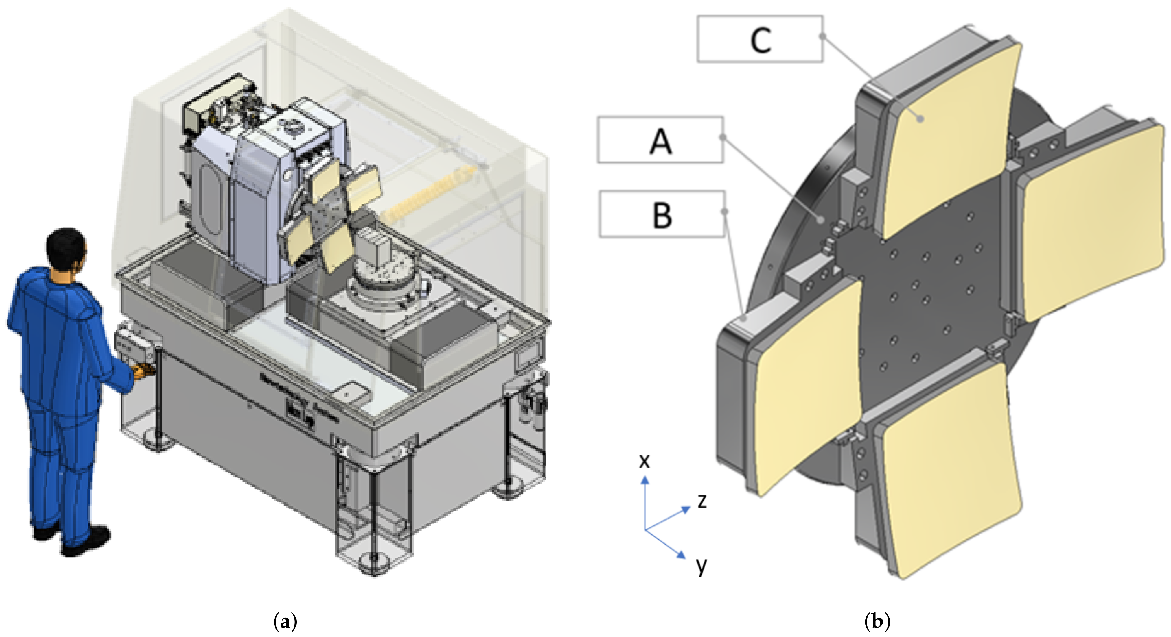
The objective of a machining fixture is to accurately position and securely hold the four segments, which collectively form a rotationally symmetrical master surface, in their designated locations. Additionally, the fixture must ensure a reliable interface transfer between the off-axis segments and the backing plate.
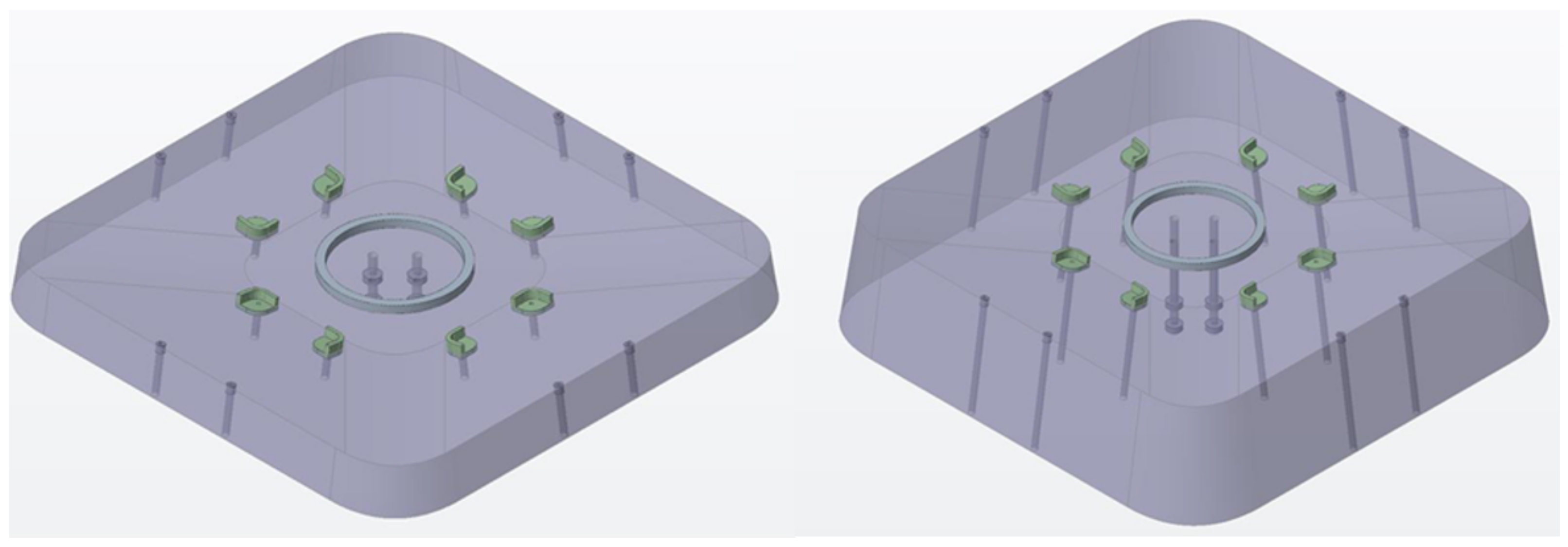
To accomplish this, the conventionally designed fixture, depicted in
Figure 1, comprises three discrete components:
Part A: The backing plate, which is affixed to the machine spindle via the central set of counterbored holes.
Part B: Removable wedges that serve to connect the mirror segments to the backing plate. These wedges also adjust the tilt of the segments according to their off-axis values and can be positioned in the X and Z directions via shims (Axis labels differ from the conventional machine ones; instead, they align with the FEA conducted in
Section 4).
Part C: The four individual segments themselves.
Figure 1.
(a) Example of a conventional fixture during machining on a Moore Nanotech 350FG at the Centre for Advanced Instrumentation at Durham University. (b) Conventional machining fixture composed of three elements. Element A is the backing plate, B are four wedges used to apply the off-axis angle on each segment and finely position each mirror on the backing plate, and C are the four segments.
As the layout of the four segments has been designed with the constraint of maintaining a thin profile to fit within the limited space of the platform, their rear faces have been aligned parallel to the tangential plane to the center of the aperture. Consequently, the use of wedges becomes necessary to compensate for this tilt. The presence of this tilt, which complicates the interface and introduces possible sources of misalignment, justifies the use of TO and its associated benefits.
2.1. Mechanical Target Requirements
The list of requirements, which defines the design objectives, is given in
Table 1.
The first requirement concerns the mass of the fixture, stipulating that it should not exceed 15 kg. This specification underscores the need for the fixture to be lightweight enough to be easily lifted onto the spindle of the machine by an operator, without relying on a crane. Since the part is machined in a vertical position as shown on
Figure 1, a heavier mass imposes additional load (bending moment) on the spindle. This increased load can potentially limit the spindle’s rotational speed, thereby extending the overall machining time. Moreover, a greater weight distributed over a larger diameter amplifies the moment and, consequently, the centrifugal force. This increase in centrifugal force induces displacements on the part during machining that give rise to form errors in the recovered mirror shape when the part is removed from the machine; hence, it is the second requirement to minimize these forces.
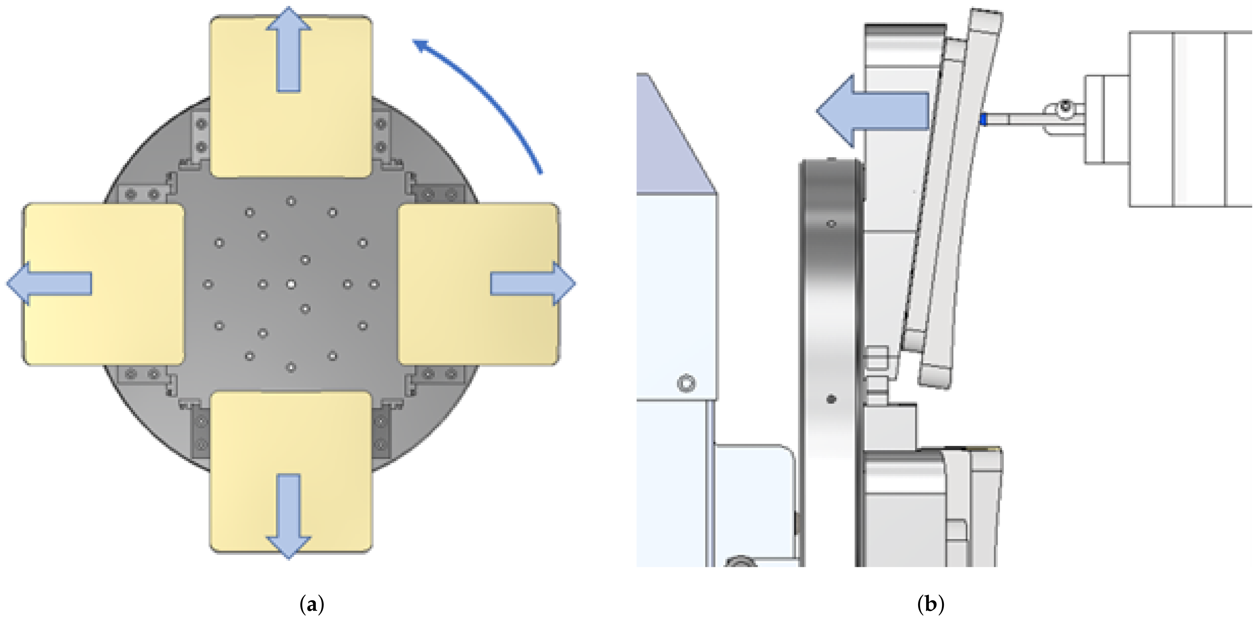
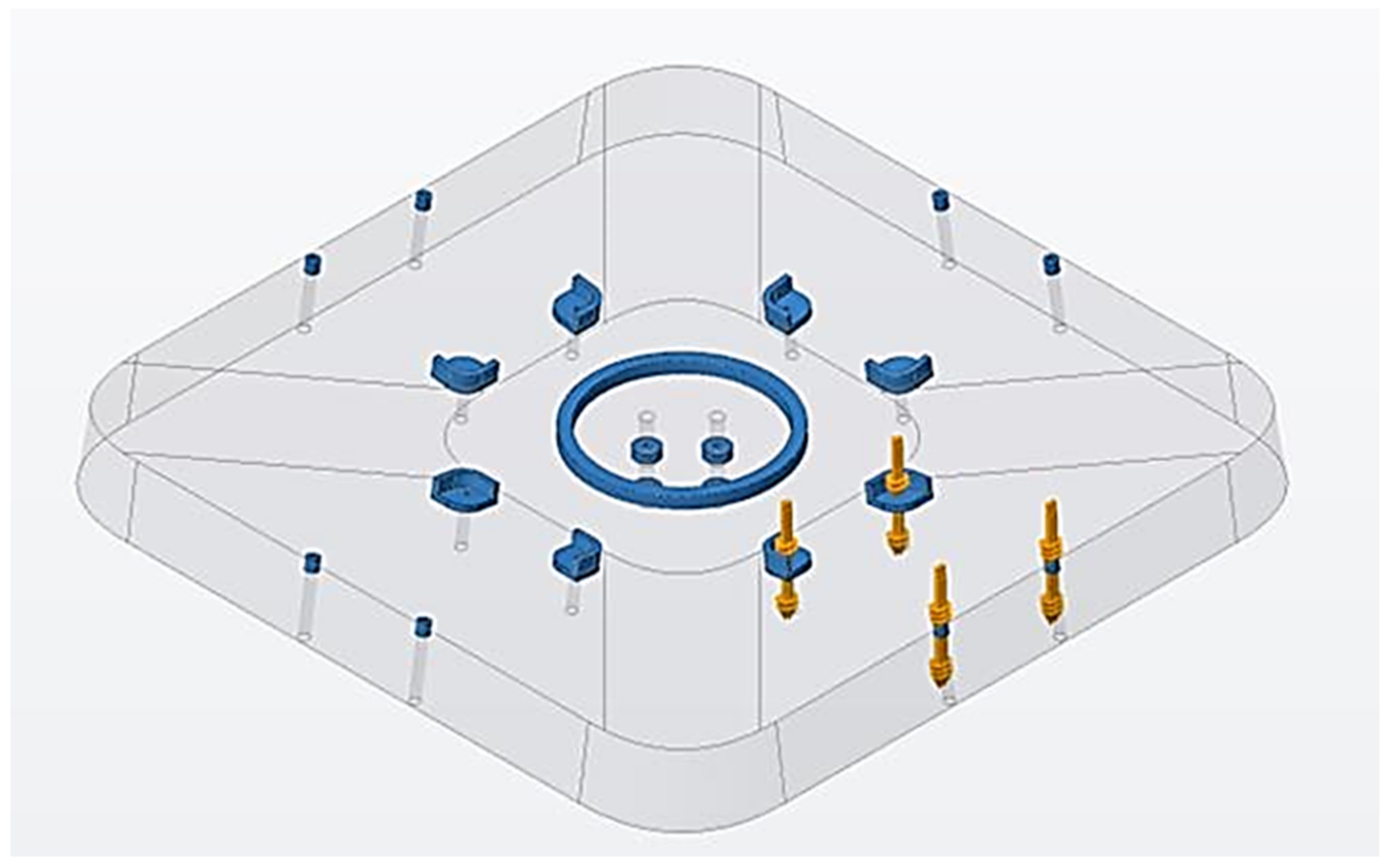
Figure 2a provides a visual representation of the force vectors applied to each segment during the machining process. The centrifugal force acting on an object can be expressed using the following equation:
Here,
represents the rotational speed in radians per second (rad/s),
r signifies the distance from the object to the axis of rotation, and
m denotes the mass of the object. While the primary force is applied radially to the segment, it is anticipated that a substantial portion of this force will translate into a component along the spindle axis due to the overhang of the wedges. This localized load will induce surface deformations on the mirror, similarly to the cutting force and shown on
Figure 2b, governed by Hooke’s law, with surface displacement varying linearly with the applied force:
In this equation,
represents the surface displacement,
L stands for the thickness of the part where the force is applied,
A denotes the surface area on which the force is exerted, and
E signifies the modulus of elasticity. Consequently, the surface displacement along the spindle axis (
) can be understood as both (i) a linear function of the tool cutting force:
and (ii) a quadratic function of the rotational speed:
Figure 2.
(a) Direction of the force induced by centrifugal force when the fixture rotates at high speed. (b) Diamond tool exerting a cutting force on the segment and machining fixture.
Figure 2.
(a) Direction of the force induced by centrifugal force when the fixture rotates at high speed. (b) Diamond tool exerting a cutting force on the segment and machining fixture.
2.2. Finite Element Analysis Parameters
FEA using Nastran [
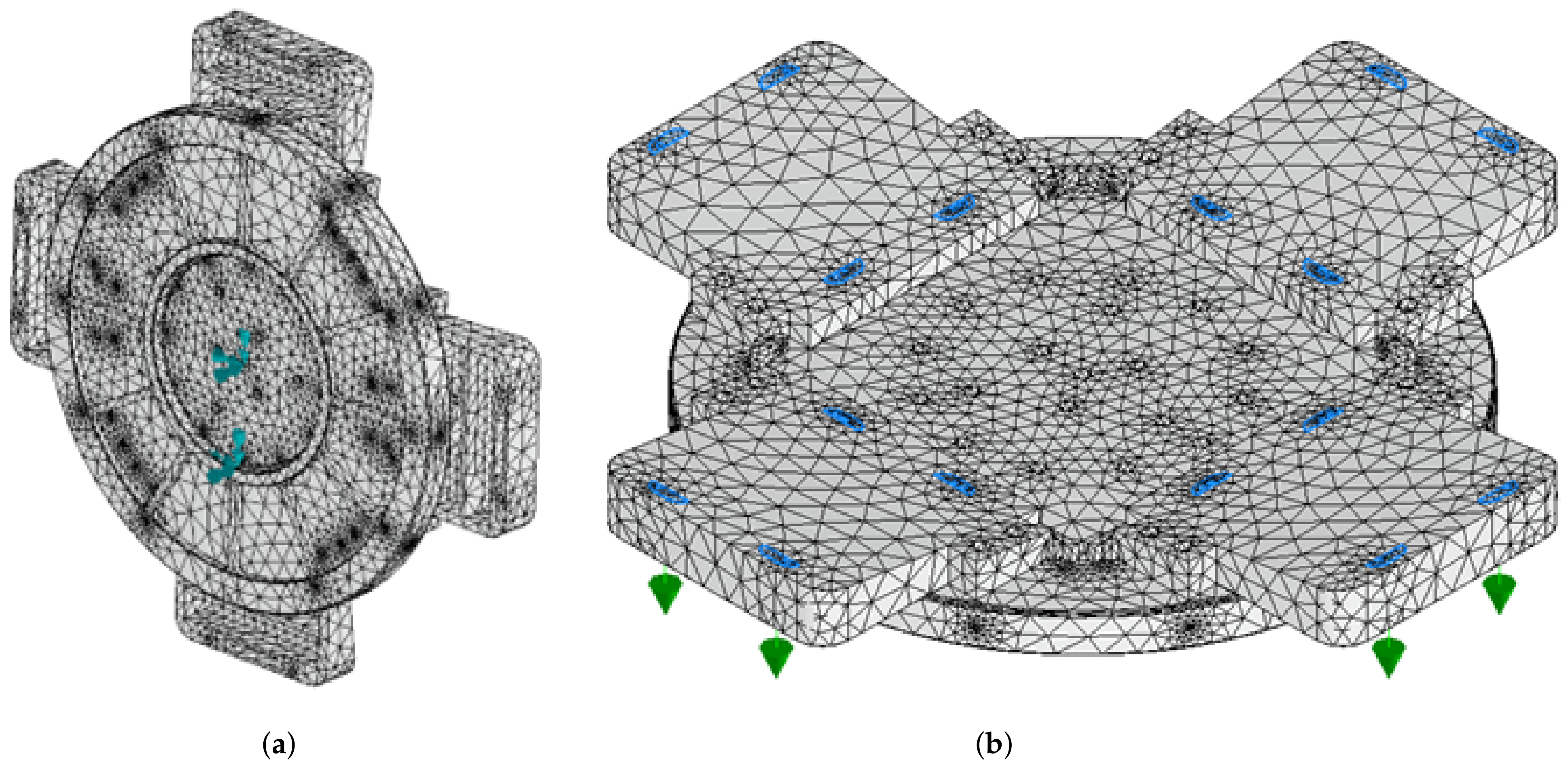
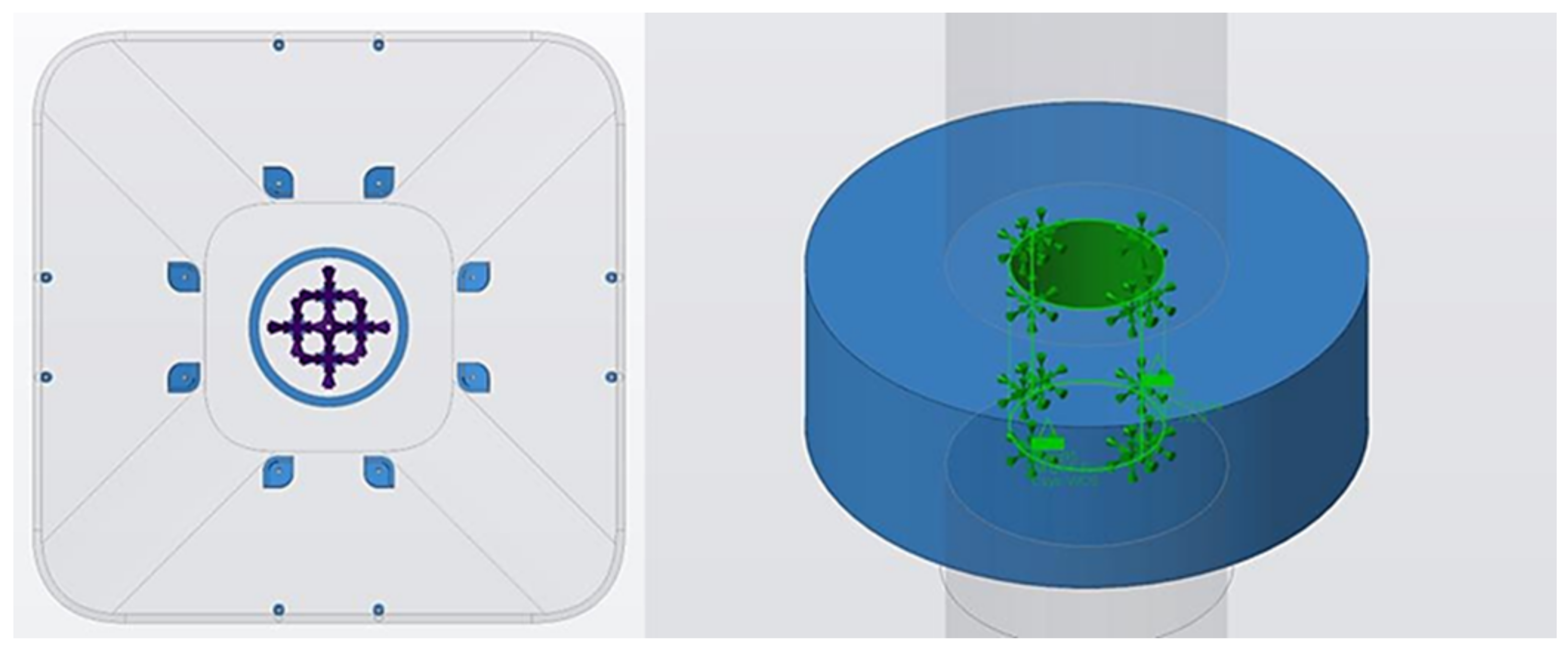
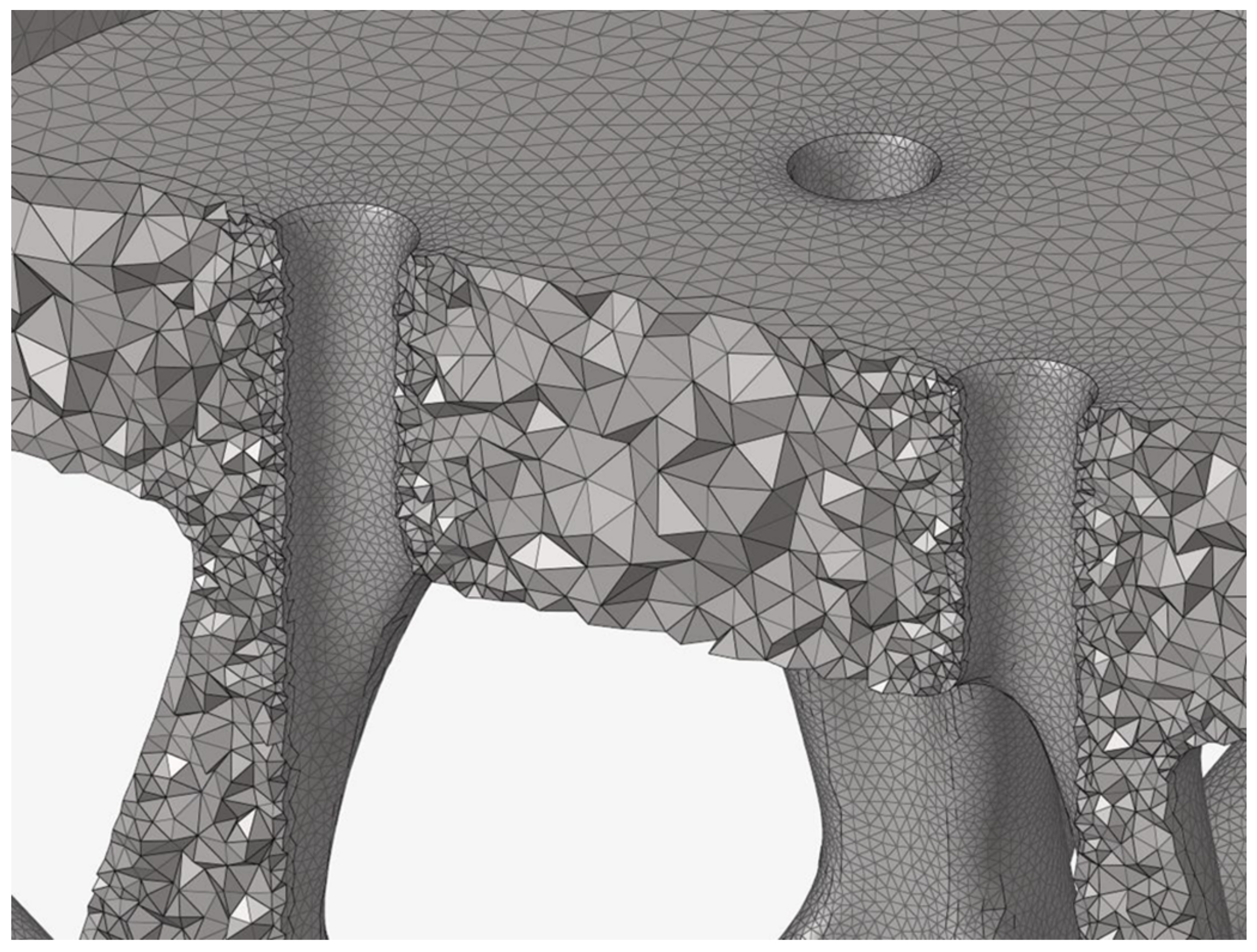
15] was used to simulate the displacement occurring on the mating faces of the fixture subjected to stress from both cutting and rotational forces. We isolated a single body part from the assembly file to simplify the transfer of deformations from the backing plate to the wedges. A mesh with element sizes of 20 mm was generated for the analysis. Fixed constraints were imposed on the bore located on the rear face of the fixture and the face in contact with the spindle, as illustrated in
Figure 3a. To represent the cutting force, a 10 N load was applied along the spindle axis to the 16 raised pads situated on top of the wedges, as depicted in
Figure 3b.
The cutting force, as described by [
16], is directly linked to the chip area and is influenced by parameters such as the depth of the cut, tool radius, and feed rate. Further investigation has revealed that tool quality and wear also play a significant role in determining the tool force [
17]. Typical cutting forces have been measured to range between 0.1 N and 1 N in the spindle’s axis of rotation. We used a value of 10 N in our simulation, applying a safety factor. Equation (
3) demonstrates that due to the linear relationship between displacement and force, the displacement results can be scaled proportionally when using a different cutting force.
In a similar manner to the approach followed by [
18], we modeled the rotational forces applied to the fixture in Nastran using a rotation force and a velocity of 7 rev/s. It is important to note that the modeling focused exclusively on the fixture, without considering the mirror segments, in order to isolate only the fixture’s contribution.
When defining the structural material parameters, a representative material with a mass density of 2.7 g/cm3. and an Elastic Modulus of 68 GPa was selected as the material for both CM and AM cases. It is worth noting that alloys commonly used in AM, such as AlSi10Mg, or traditional aluminum alloys like 6061, exhibit very similar structural properties.
It would make sense to use a similar material for the telescope’s primary mirror segment and the telescope structure to enable homogeneous thermal expansion in different temperature regimes, especially for machining, alignment, integration, and in-orbit operation.
2.3. FEA Results—Conventional Fixture
The total mass of the assembly comprising the backing plate and the wedges is 15.5 kg.
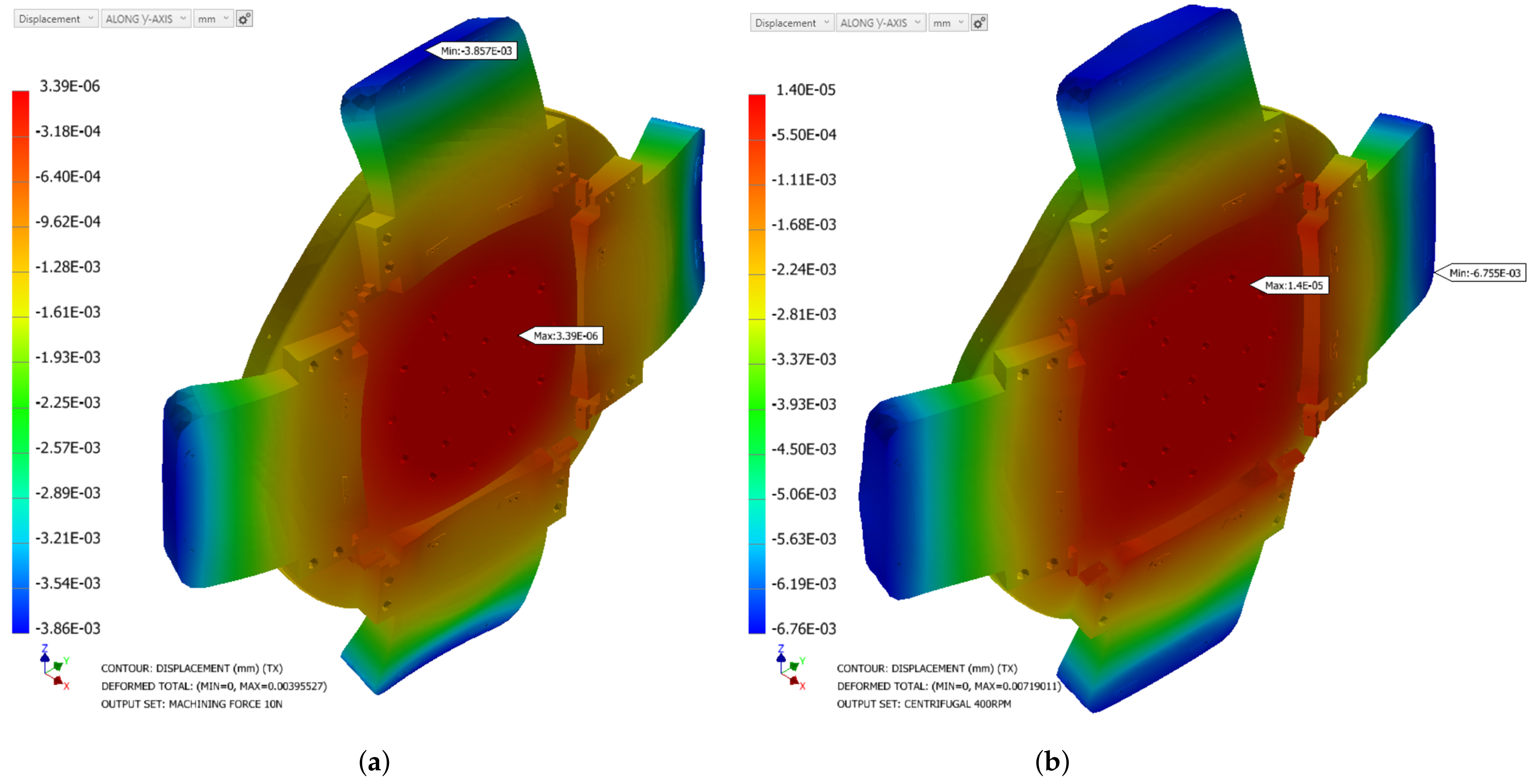
The FEA results are presented in
Figure 4 and
Table 2, showcasing the deformation along the axis corresponding to the optical axis. With a cutting force of 10 N in
Figure 4a, the deformation measures approximately 3.9
m PV. Notably, the maximum deformation is observed above the overhang, highlighting the need for a significantly stiffer and more rigid support in that area. With a more realistic cutting force of 1 N, the deformation would be around 390 nm, which would become acceptable for a IR telescope, especially considering that the distortion would also be limited to the area of the pads and not the entire fixture, which is how it has been considered here.
Figure 4b illustrates the displacement outcome caused by rotational forces of 400 RPM, again along the spindle axis. As significant displacement is observed at approximately 6.8
m, it is advisable to refrain from using the fixture at rotational speeds exceeding 90 RPM, which would induce a residual deformation around 350 nm.
Due to the lower deformation induced by gravity, our subsequent optimization will primarily focus on reducing the deformation caused by cutting and rotational forces.
4. Results
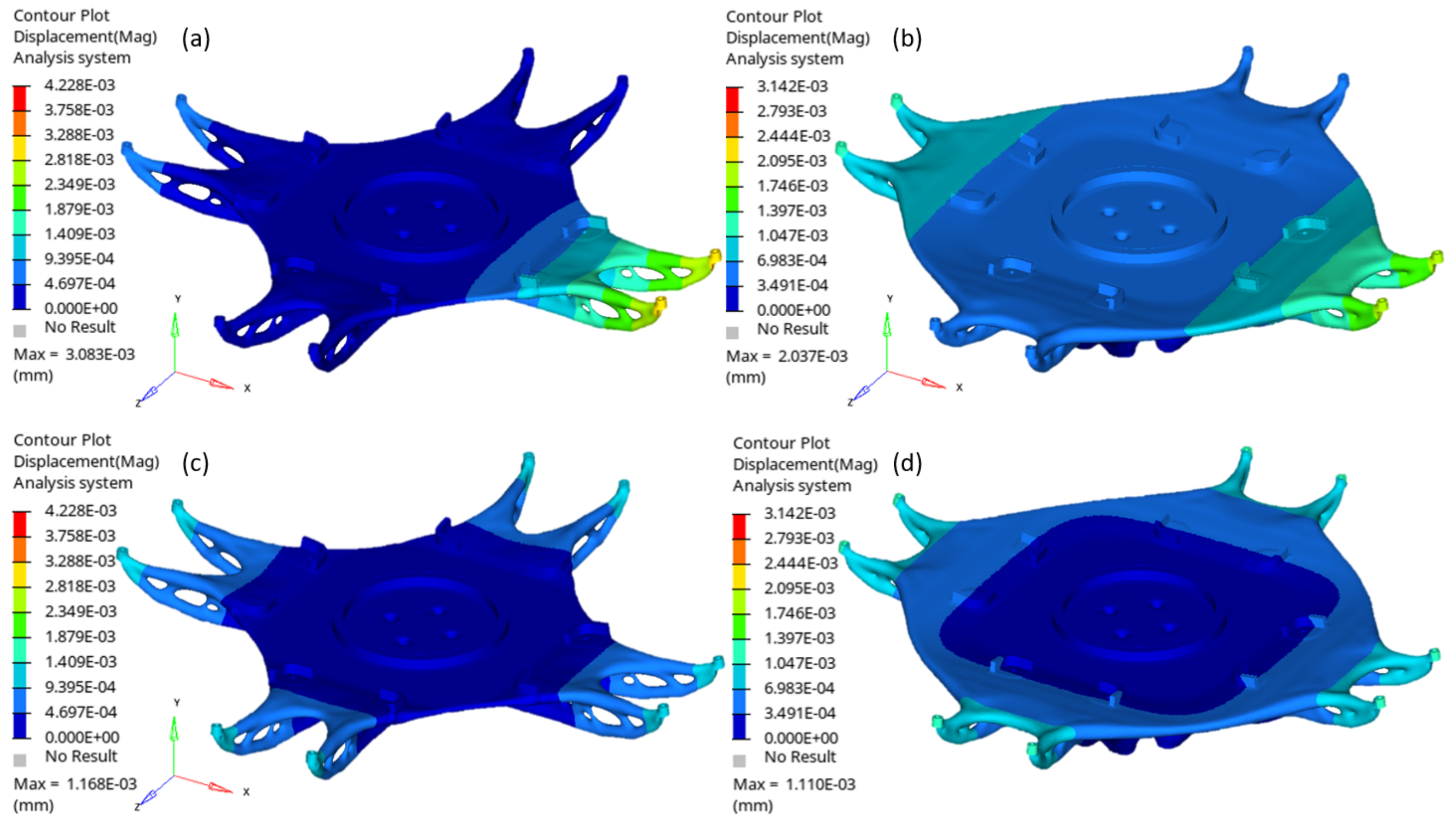
Two TO outputs were successfully produced and met the specified design criteria, as highlighted in
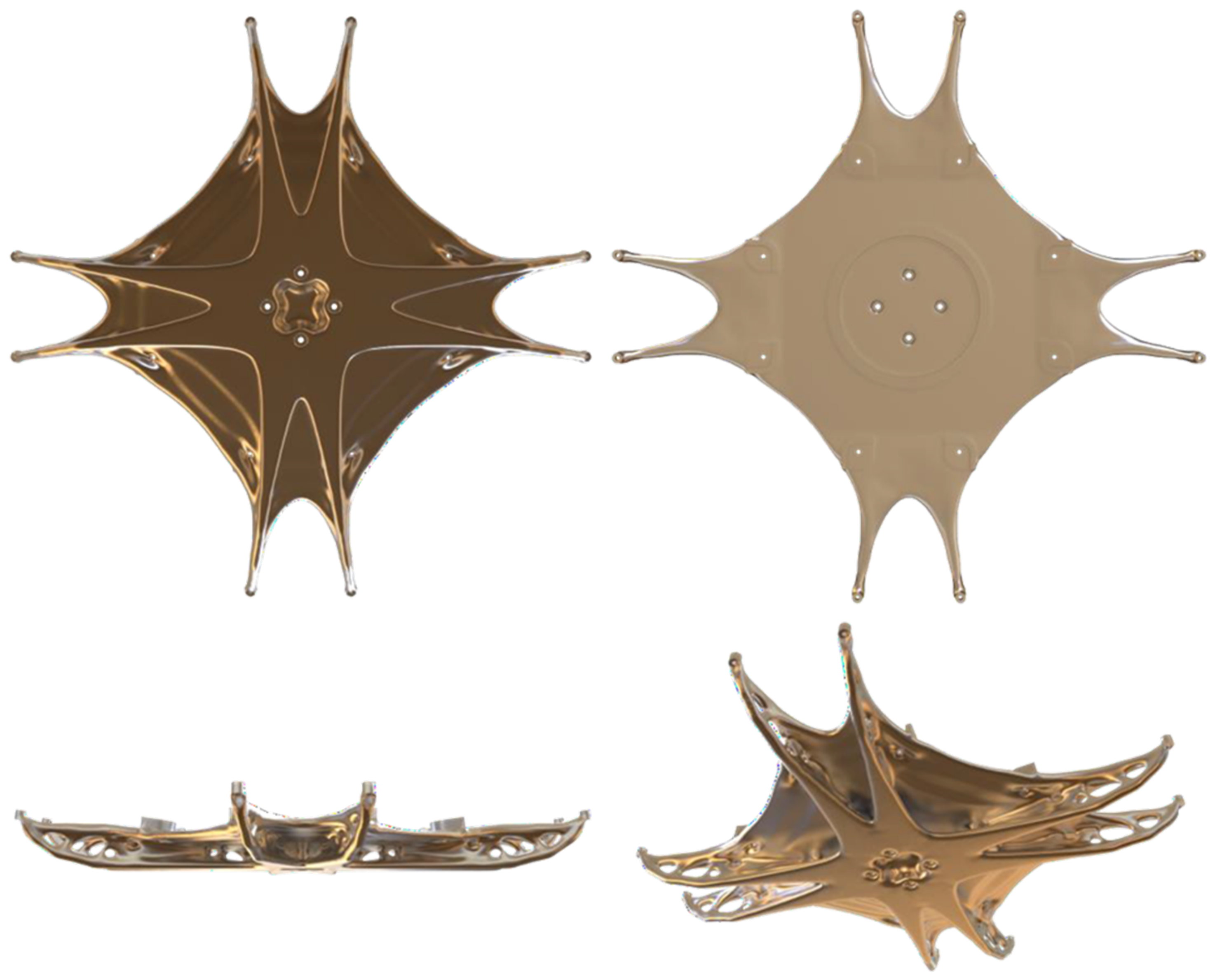
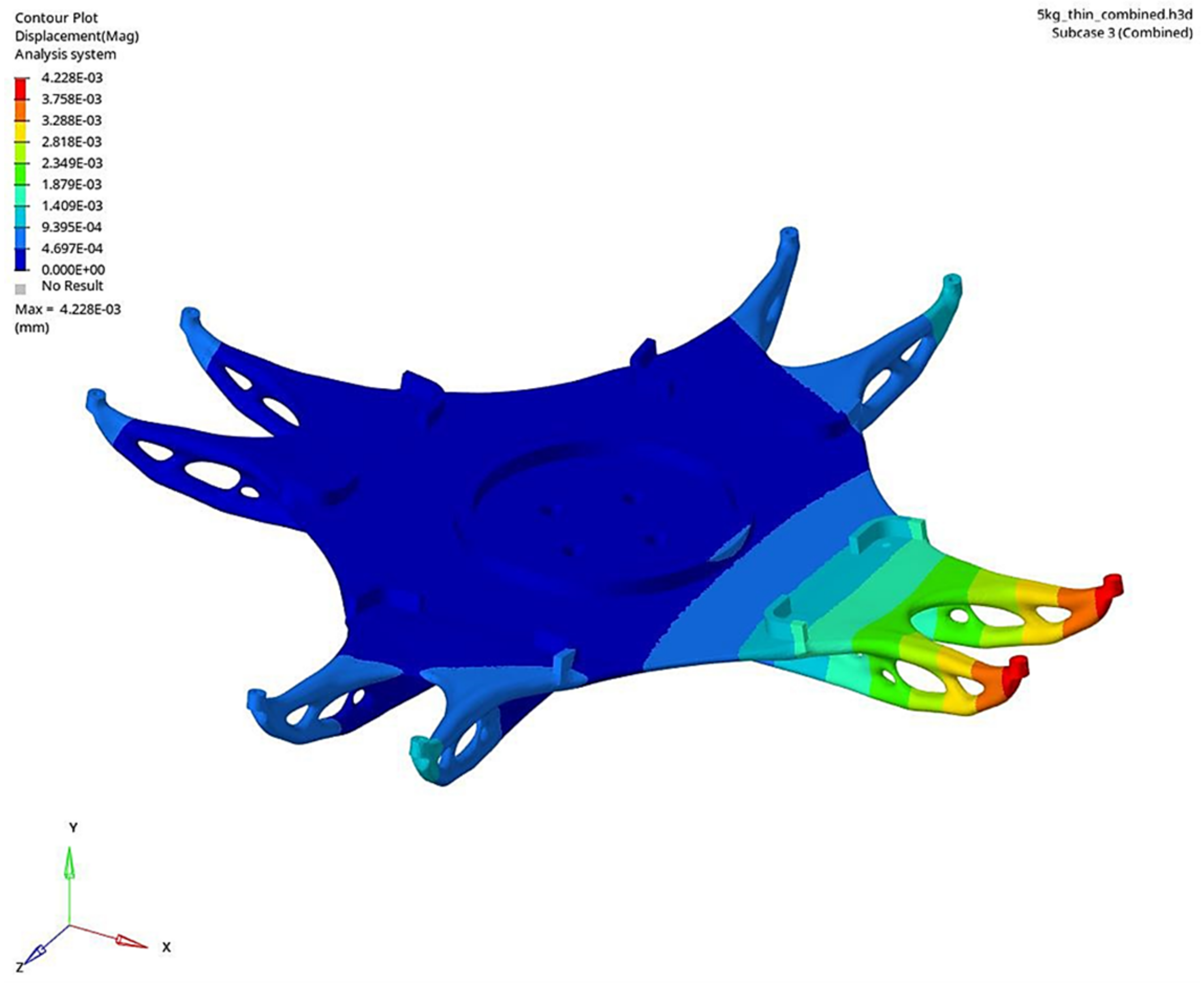
Table 5. An additional load case, combining both rotational and axial loads, was evaluated to better approximate the real machining setup. This combined load case resulted in the greatest deflection, with the findings presented in the subsequent figures. The TO outputs are shown in
Figure 9 and
Figure 10. Detailed deflection plots for each individual load case are shown in
Figure 11,
Figure 12 and
Figure 13. Although peak stress levels were recorded, it is important to note that prior studies have determined that stress is not a significant concern for the materials selected for these designs.
The output of the TO with the shorter design envelope and 5 kg mass target, as well as the peak deflection contour plot, are shown in
Figure 9 and
Figure 11.
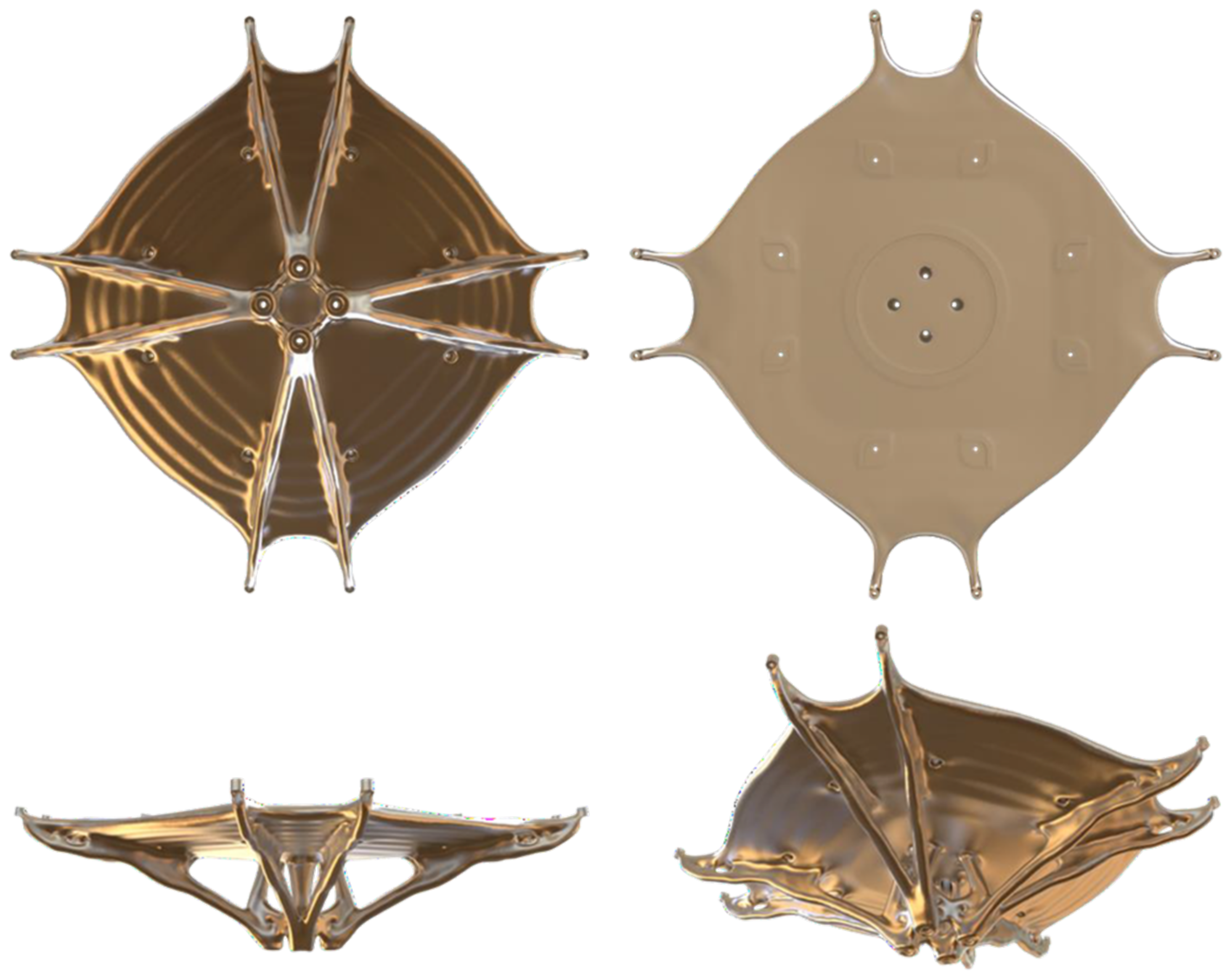
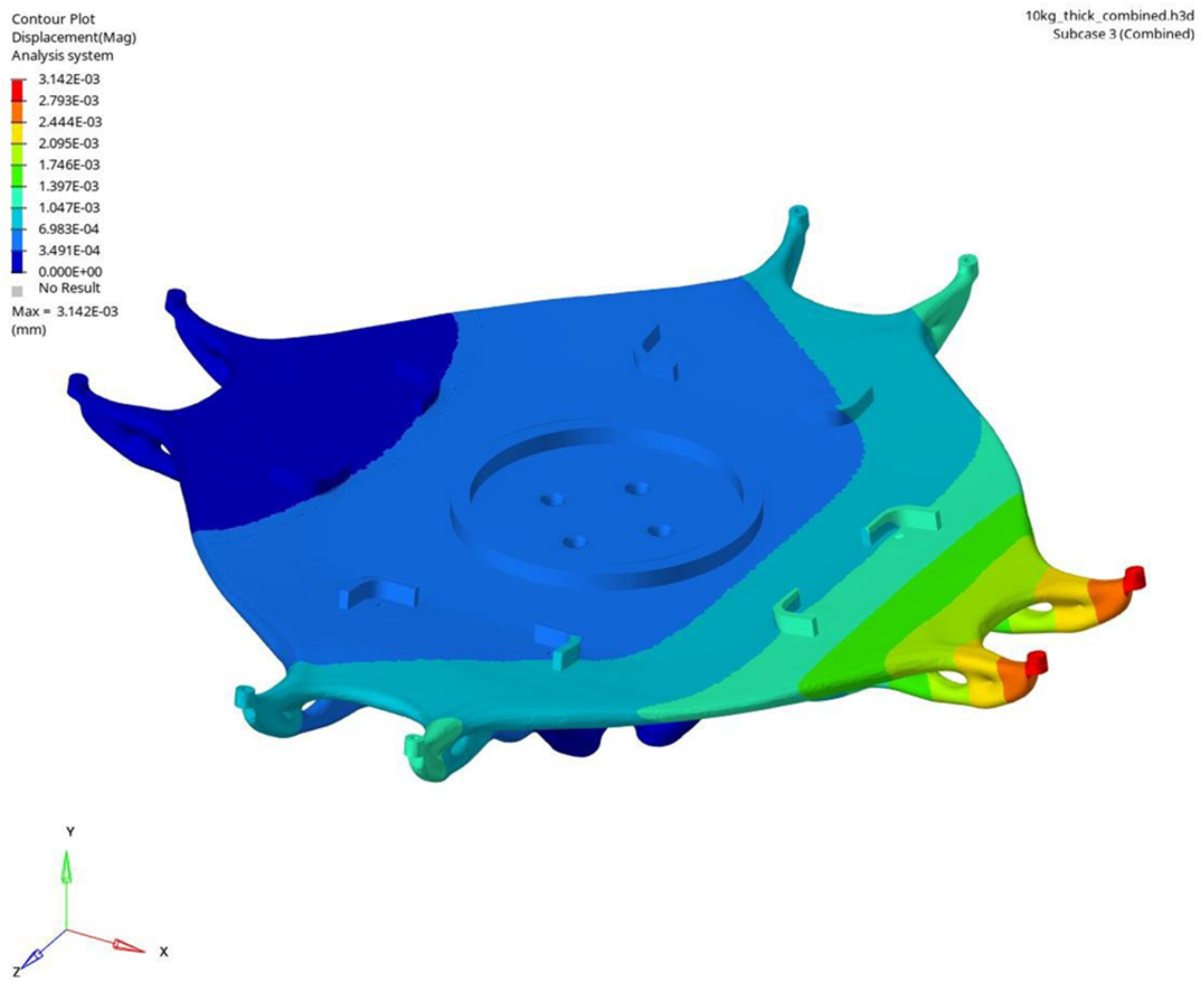
The output of the TO with the longer design envelope and 10 kg mass target, as well as the peak deflection contour plot, are shown in
Figure 10 and
Figure 12.
Comparing the results of the design envelopes, the short envelope design, with a mass of 5.2 kg, demonstrated peak deflections slightly higher than the long envelope design, which weighed 10.2 kg. Specifically, under combined load conditions, the short envelope recorded a peak deflection of 4.23 µm compared to 3.14 µm for the long envelope. This difference highlights the long envelope’s slightly superior performance in minimizing deflection under load, which could be attributed to its increased mass and altered geometry. Moreover, the peak stress in the long envelope design was marginally higher (1.59 MPa) compared to the short envelope (1.24 MPa), yet both values were significantly lower than the stress limit of 116 MPa, confirming the robustness of both designs. Unlike the CM design, the TO outputs account for the stiffness of the mirror in the optimization. The resultant geometries are truss-like and have members directly connecting the mounting pads on the mirrors to the spindle. Note how the plane of the trusses acts to reduce the displacement along the spindle axis. These designs also feature reinforced support at critical points to minimize deformation under various applied loads.
The summarized results are presented in
Table 6, where the mass and performance of the CM design are taken as a reference and compared with both TO
1 and TO
2. In addition to the actual mass and deformation values for TO
1 and TO
2, an ‘improvement’ factor is provided as a percentage, reflecting the reduction in mass or displacement achieved.
A significant 80% reduction in deflection was achieved when the assembly was subjected to rotational force, while improvements of 21% and 47% were observed in the deflection induced by cutting forces for the 5 Kg and 10 Kg TO, respectively. As mentioned, the recorded stress levels, though monitored, were not a primary concern, primarily due to the high stress tolerance of the AlSi10Mg material used in the designs. This material offers a favorable combination of strength and flexibility, making it well suited for applications requiring both lightness and durability.
5. Discussion
TO and AM have the potential to enhance the precision and efficiency of the Single-Point Diamond-Turning manufacturing process by optimizing fixture rigidity and resilience to the manufacturing stress. They also have the potential to further reduce the weight of large assembly and aperture, especially for cases such as deployable primary mirrors, helping with the handling of parts and the iteration between machining and “off-machine” metrology.
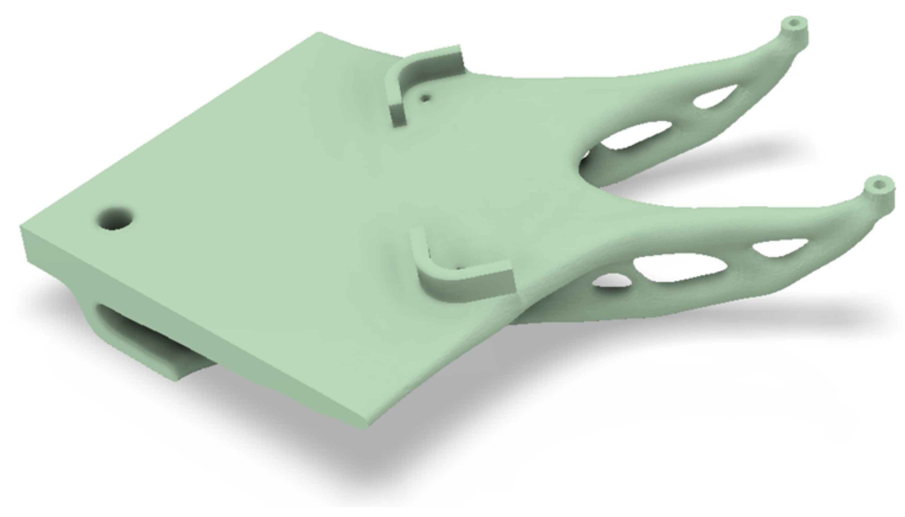
Although there are some clear benefits to using AM, 3D printing of large parts, such as the ones presented in this paper with a diameter of 600 mm and a thickness of 200 mm, can be challenging and the process may be long and costly. The volume capacity of current LPBF machines can also be limited to smaller dimensions. One solution could be to split the whole assembly into four rotationally symmetrical sections (one section is shown in
Figure 14), which could therefore be printed on conventional LPBF machines. This segmentation not only facilitates printing but could also significantly reduce the stress and potential thermal distortions typically encountered in large-scale LPBF printing. Each section could be designed to be self-supporting at a 45-degree critical angle, optimizing the printing process by minimizing the need for additional support structures and streamlining post-processing, despite a possible increase in Z height and print time. The four subassemblies can then be reassembled on a backing plate and positioned on the machine spindle as one single unit. The flat interface with the segment can be prepared and rectified with a high-speed ball end mill [
21] so that all planes are post-processed in the same setup, minimizing potential errors induced by removing and reattaching the fixture to the machine’s spindle.
An alternative method of manufacture could be explored using investment wax casting [
22], a process renowned for its accuracy. It involves creating a wax model of the entire TO fixture (or a sand mold). This model is then encased in a refractory material to form a mold. Once the mold is heated, the wax melts away, leaving a cavity in the shape of the fixture. Molten metal is then poured into this cavity, creating a single, unified piece that mirrors the intricate design of the TO fixture. This method could be beneficial for producing complex geometries and large-scale components, which are often challenging or impractical with LPBF due to size limitations and the need for support structures. Additionally, casting the fixture as one piece significantly reduces the risks associated with segmenting and reassembling multiple parts. It eliminates potential misalignments or inconsistencies that might arise from assembling several printed sections. This ensures a higher degree of structural integrity and uniformity in the final product.
6. Conclusions
The topology optimization process at AMRC yielded two distinct outputs, primarily focused on reducing mass while maximizing stiffness. These designs feature reinforced supports at crucial points, balancing lightweight construction with enhanced structural integrity. FEA revealed that both designs significantly outperformed the reference CM model. Specifically, TO1 demonstrated a 66.45% mass reduction and substantial decreases in deformation (82.79% under centrifugal forces at 400 RPM and 21.03% under 10 N cutting forces). Similarly, TO2 achieved a 34.19% mass reduction, an 83.68% reduction in deformation from centrifugal forces, and a 47.69% reduction in deformation from cutting forces. In-depth examination of the topology optimization for the metal optics fixture presented an innovative design that not only minimized mass but also met or surpassed deflection standards. Both design variants shared key structural features, such as truss-like arms extending from the spindle interface to the metal optics interfaces, enhancing bending stiffness. A distinctive plate-like feature on the design envelope’s upper surface, formed in response to rotational loads, was also observed. Both designs exceeded mechanical requirements, suggesting that a more aggressive optimization approach could further reduce weight. However, our conservative strategy incorporated additional factors like rotational symmetry and dynamic acceleration criteria, ensuring compatibility with PTC Creo Version 9.0.2.0. This approach, combined with additive manufacturing considerations, underscores the transformative potential of TO and AM in refining Ultra-Precision manufacturing processes.


