Article

Parametric Analysis of the Toothed Electromagnetic Spring Based on the Finite Element Model

1
College of Mechanical Engineering and Automation, Fuzhou University, Fuzhou 350116, China
2
Metal Rubber Engineering Research Center, Fuzhou University, Fuzhou 350116, China
*
Authors to whom correspondence should be addressed.
Aerospace 2023, 10(9), 750; https://doi.org/10.3390/aerospace10090750
Submission received: 3 July 2023 / Revised: 19 August 2023 / Accepted: 20 August 2023 / Published: 25 August 2023

Abstract

:
Active vibration control shows excellent performance in vibration isolation. In this work, the finite element model of a toothed electromagnetic spring (TES) is established using ANSYS Maxwell software. Subsequently, a static characteristic experiment of the TES is carried out, and the validity of the model is verified. Based on the established finite element model, the influence of key structural parameters on the static characteristics of the electromagnetic spring is analyzed. The results show that the parameters of the magnetic teeth have a significant impact on the performance of the electromagnetic spring. As the number of teeth increases, the electromagnetic force first increases and then decreases. With the increase in the tooth height or width, the maximum electromagnetic force gradually increases to the maximum value and then stabilizes. It should be noted that the tooth width simultaneously affects the maximum electromagnetic force, stiffness characteristics, and effective working range of the TES. This work provides a basis for further exploring the application of electromagnetic springs within the field of active vibration control.

1. Introduction

Mechanical vibration is ubiquitous in engineering practice. Vibration may lead to fatigue damage, vibration noise, and machine failure [1,2,3,4]. Passive vibration isolation, also known as passive vibration reduction, has been widely used in vibration isolation systems due to its simple structure and low cost. Passive vibration isolation does not require an energy source or an external power or control system during operation. Common passive vibration isolation systems are usually composed of elastic elements, damping elements, or inertial elements, such as steel springs, rubber pads, and polymer materials [5,6,7,8]. Due to the high precision requirements of precision manufacturing and measurements and the need for environmental noise reduction [9], conventional passive control methods can hardly meet the increasingly stringent vibration control requirements. For example, the control of low-frequency vibrations is not satisfactory and cannot be adjusted in real time by changing the external excitation frequency. In order to overcome the limitations of traditional vibration control methods and achieve more accurate, efficient, and flexible vibration control, researchers have started to study new control methods. Active vibration control has, therefore, become a popular research topic [10,11,12]. Electromagnetic springs are characterized by a fast response [13,14,15,16], large displacement and output [17,18,19], and easily integrating with vibration energy harvesting [20,21]; they also have wide application prospects [22,23]. Kallenbach et al. [24] used high-energy permanent magnets in electromagnetic springs to increase the output of the electromagnetic force and applied them to the medical field. Kim et al. [25] proposed two types of nonlinear quasi-zero stiffness isolators capable of achieving high damping while reducing the peak frequencies. Mofidian et al. [26] proposed a vibration isolation system that combined a spring and a damping material. The system consisted of a ring-shaped permanent magnet fixed at the top and bottom of the cavity and a solid magnet suspended between them. The copper wire coil was fixed around the suspended magnet. When the suspension magnet vibrates, it moves vertically to produce a magnetic field in the coil. As the magnetic field produced is opposite to the external magnetic field, a damping force is generated. Olaru et al. [27] designed a novel variable-stiffness actuator based on an electromagnetic spring. The device consisted of two mutually exclusive magnets, and the electromagnetic force acting between them could be changed by controlling the magnitude and direction of the current flowing through the coil, thereby causing a change in stiffness. Liu et al. [28] designed a semi-active vibration absorber with adjustable stiffness, which exhibited excellent vibration absorption at each test point and at various frequencies.
In this work, the static characteristics of a toothed electromagnetic spring (TES) are studied. Firstly, the finite element model of the TES is established using ANSYS Maxwell software. Then, a static characteristic experiment of the TES is carried out, and the validity of the model is verified. Furthermore, the influence of the structural parameters of the teeth on the static electromagnetic force of the TES is analyzed based on the finite element model. This work provides a basis for the optimal design of magnetic teeth for electromagnetic springs. This work is organized as follows. Section 2 briefly introduces the structure and working principle of the TES. In Section 3, the finite element simulation model is established. In Section 4, the experimental platform that was built to verify the accuracy of the finite element simulation is presented, then the influence of different parameters of the magnetic teeth on the electromagnetic force is analyzed. Finally, our conclusions are summarized in Section 5.

2. Finite Element Simulation

2.1. Structure of the TES

The TES has an axisymmetric structure and is mainly composed of a motor, a stator, and a coil. A schematic of its structure is shown in Figure 1. The actuator and stator of the TES are both equipped with a circular toothed structure of the same size, and there is an air gap between each pair of toothed structures. The coil is usually wound around the rotor. When current flows through the coil, the rotor generates an electromagnetic field; the lines of this field go along the rotor magnetic teeth, through the air gap, into the stator toothed structure, and then back into the rotor through the air gap, forming a closed circuit.

2.2. Finite Element Simulation

2.2.1. Finite Element Model

The electromagnetic field theory consists of Faraday’s law of electromagnetic induction, Ampere’s circuital law, Gauss’s law, and Gauss’s law for magnetism, namely
× E = B t × H = J + D t D = ρ B = 0 ,
where ∇ is the vector operator, E is the electric field strength, B is the magnetic flux density strength, H is the magnetic field strength, J is the conduction current density, D is the electric flux density, and ρ is the charge volume density.
The vector magnetic potential A is introduced to separate the electric field and magnetic field, which satisfies B = ∇ × A. In addition, A satisfies Faraday’s law of electromagnetic induction and Gauss’s law of magnetic flux. The partial differential equation of the magnetic field is obtained by substituting A into Ampere’s circuital law and Gauss’s law, that is
2 A μ ε 2 B t 2 = μ J .
For planar problems, ∇ = (/∂x, /∂y); therefore, Equation (2) can be written as
x 1 μ A x + y 1 μ A y = J ,
where ε, and μ represent the dielectric constant, magnetic permeability of the material, respectively.
The Newton–Raphson method is used, and the solution model is as follows:
r = x 1 μ A ˜ x + y 1 μ A ˜ y + J 0 R i = ω i r d Ω = 0 ,
where Ω is the solution domain, Ã is the approximate solution to be solved, r is the minimum value of the residual on Ω, Ri is the weighted integral, and ωi is a weighted function.

2.2.2. Grid Demarcation

The TES has an axisymmetric structure, so a two-dimensional plane model is established for the simulation analysis instead of a three-dimensional model. The end cover of the TES consists of a non-magnetic conductive material, which does not affect the magnetic circuit structure. Therefore, the end cover is simplified in the geometry of the finite element simulation model. The established magnetic circuit simulation model is presented in Figure 2, and the magnetic circuit parameters are listed in Table 1. It is worth noting that due to the limited structural deformation generated by the electromagnetic spring, the influence of the structural deformation is ignored in the simulation in this work.
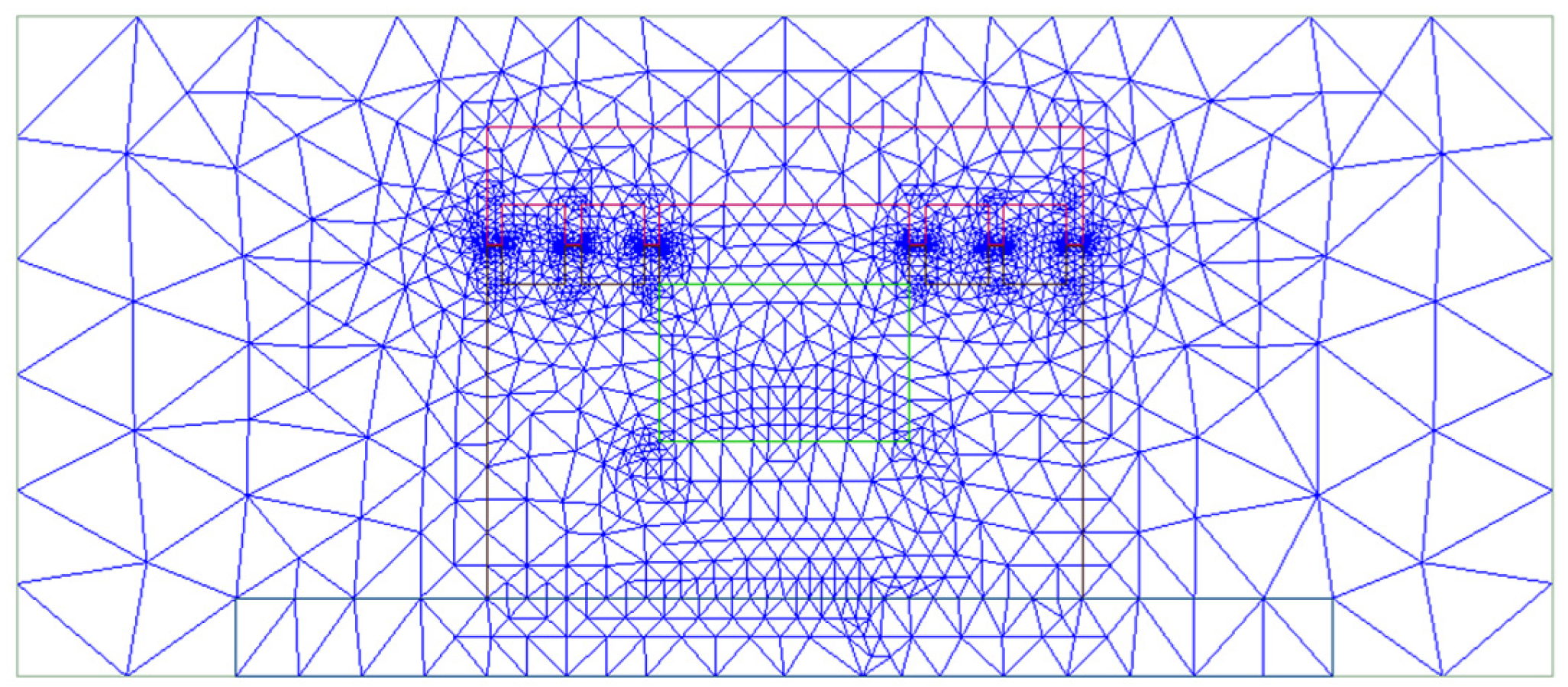
The finite element meshing determines the accuracy and reliability of the model. Generally, the higher the number of mesh elements used, the smaller the discretization error generated by the finite element model. However, an excessive number of mesh elements will increase the calculation time. Therefore, choosing an appropriate mesh is of utmost importance in finite element simulations. In this work, we select a triangular mesh for partitioning and a magnetostatic for solving. The maximum length of the grid in each region of the model is limited, and the parameter settings for the grid in each region are listed in Table 2. The grid division result is shown in Figure 3, and the coils are meshed more densely to improve accuracy.

2.2.3. Application of Constraints

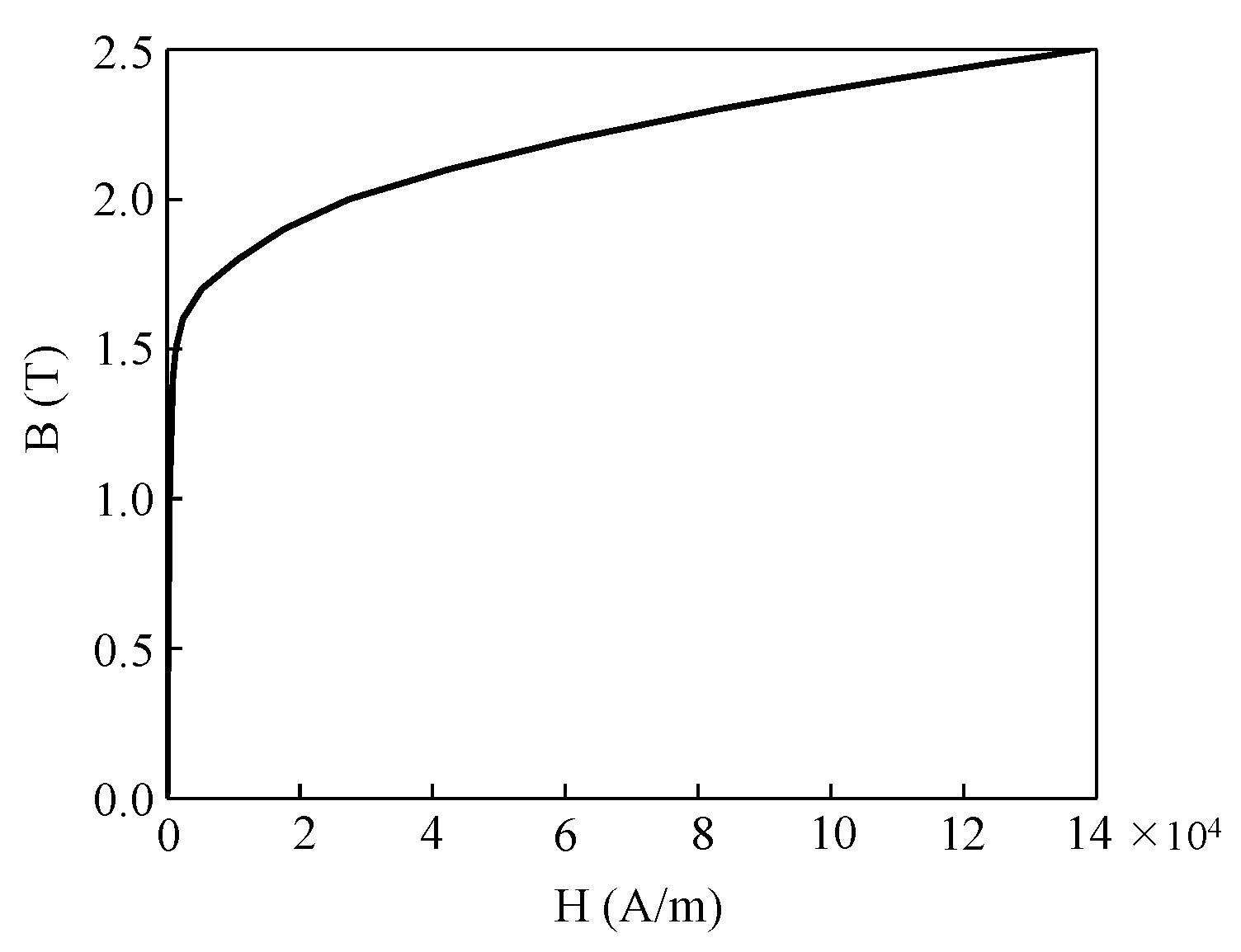
The rotor and stator of the TES are made from low-carbon steel with stable magnetic properties (DT4), which is not included in the Maxwell material library. Therefore, the material properties need to be defined based on the magnetic properties of DT4. The magnetic field intensity B and magnetic induction intensity H (BH) curve of DT4 are shown in Figure 4. The rotor and coil are made of steel and copper, which have a relative permeability of approximately 1. The remaining materials in the solution domain of the model are defined as being air, which also has a relative permeability of 1.

2.2.4. Results

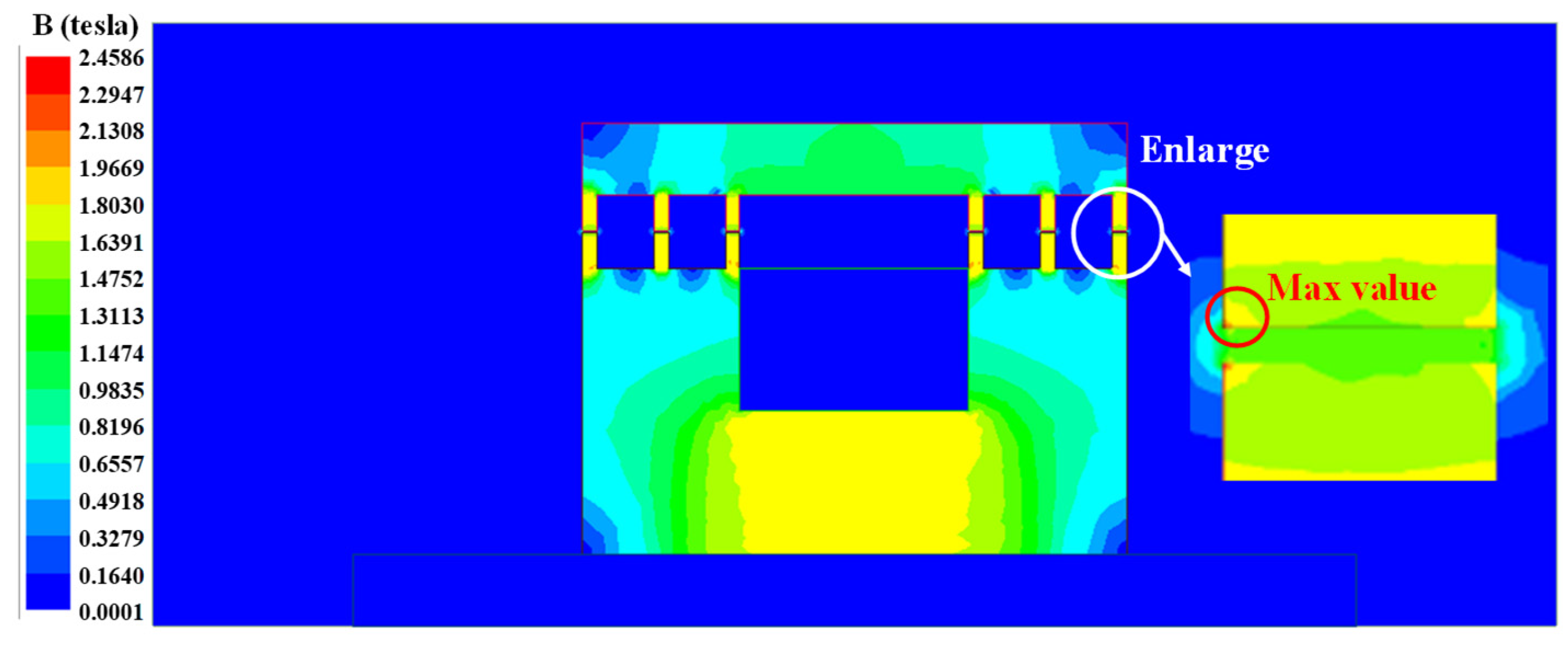
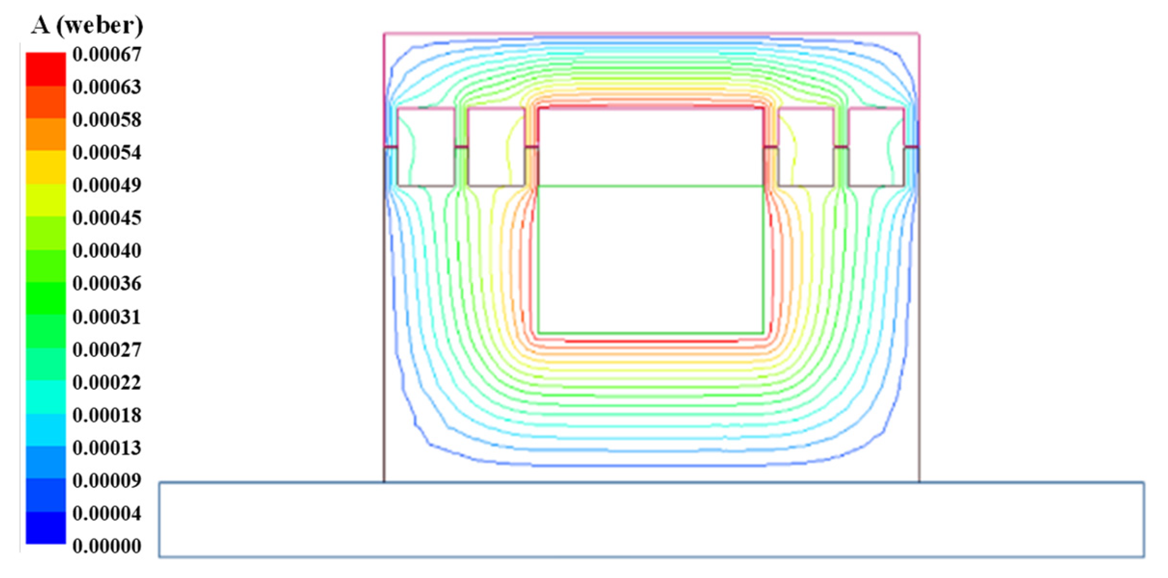
After the geometric modeling of the electromagnetic spring, boundary conditions need to be defined for the model to facilitate the subsequent magnetic field analysis. The balloon boundary conditions, also known as infinite boundary conditions, are used in this work. The scope of the balloon boundary is to surround the entire model, as shown in the outermost border of Figure 2. When solving the balloon boundary conditions, the boundary at infinity is regarded as a spherical balloon so that the magnetic field at the boundary can be treated reasonably. The magnetic flux density distribution and magnetic force line distribution of the model, when the TES is in the equilibrium state, are shown in Figure 5 and Figure 6, respectively. It can be seen from Figure 5 that the magnetic flux density at the magnetic teeth of the electromagnetic spring is significantly higher than that at other locations, which indicates that the design of the electromagnetic spring is reasonable. From Figure 6, the magnetic field distribution of the model spring is basically consistent with the magnetic circuit distribution, and almost no leakage occurs.

3. Model Verification

The experimental setup used to measure the static electromagnetic force of the TES is shown in Figure 7. Firstly, the electromagnetic spring actuator was set to be in equilibrium, and this position was set as the displacement origin. Then, direct current was applied to the electromagnetic coil, and the electric cylinder was controlled to move the actuator within a certain range. It is worth noting that the movement was carried out in steps of 0.1 mm, and the electromagnetic force and displacement data were recorded. After completing one experimental cycle, the input direct current was adjusted in steps of 0.5 A until the electromagnetic force and displacement measurements were completed at 0.5–2.5 A current. The main technical specifications for the experimental system are illustrated in Table 3.
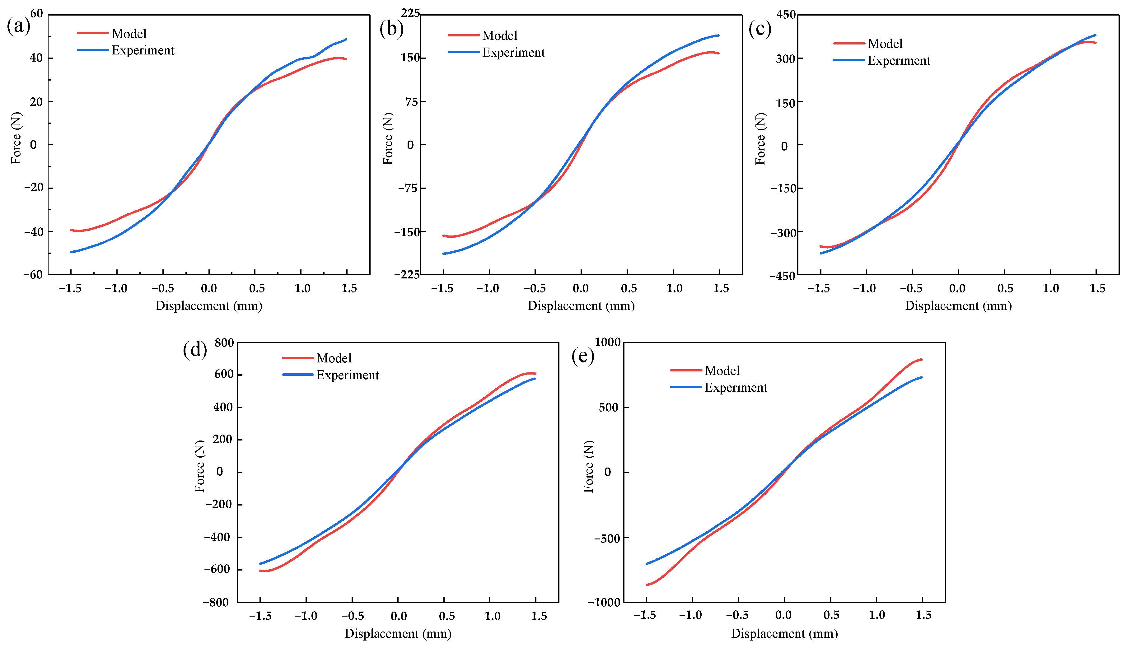
The comparison between the experimental and simulated electromagnetic force (F) generated by the TES and the axial displacement of the rotor (x) curves undercurrents of 0.5–2.5 A, as shown in Figure 8. It can be seen from Figure 8 that the finite element simulation results are in good agreement with the experimental data. The calculation results overlap to a great extent with the experimental data when the displacement is small, but when the displacement is large, the discrepancy between the curves increases accordingly. It is worth noting that when the displacement is large, the discrepancy first decreases and then increases with the current. The main reason for this phenomenon is that there are machining and assembly errors in the actual processing of the electromagnetic spring [20,21]. Furthermore, the structural deformation of the electromagnetic spring also causes a deviation between the measured displacement and the actual displacement. Thus, the normalized residual analysis ε ¯ is adopted to evaluate the prediction accuracy. The results of the normalized residual analysis are shown in Figure 9, and the normalized residual analysis can be expressed as
ε ¯ = y i y ^ i y i max y i min ,
where yi is the observed value, ŷi is the predicted value, and yimax and yimin are the maximum and minimum observed value, respectively.
Figure 9 illustrates that the normalized residual points predicted by the model established in this work and the actual experimental results fall basically in the horizontal band region of −0.2–0.2, and there is no extreme point. This phenomenon indicates that the established model can effectively reflect the force–displacement curves of the TES.
Furthermore, the residual sum of squares (RSS) and the total sum of squares (TSS) parameters were employed to obtain a more quantitative explanation, and the accuracy of the model was verified by a correlation index R2. The quantitative analysis of model accuracy was performed according to Equations (6)–(8), and the results are illustrated in Table 4. Obviously, R2 was quite close to 1, indicating that the prediction accuracy of the model was substantially high.
R S S = i = 1 n y i y ^ i 2 ,
T S S = i = 1 n y i y ¯ i 2 ,
R 2 = 1 R S S T S S
where n is the number of data, and ȳi is the mean of the observed value.

4. Parametric Analysis

The finite element simulation model established above can accurately describe the force–displacement curves of the TES. The tooth height, tooth width, and tooth number of the electromagnetic spring affect the static electromagnetic force of the TES, but experiments cannot be easily conducted to study this influence. Therefore, the finite element model is used to study the influence of the parameters of the magnetic teeth on the characteristics of the generated electromagnetic force.
The static characteristics of the magnetic-toothed electromagnetic spring mainly refer to the electromagnetic force of the electromagnetic spring under different displacements. Based on the finite element model established in the previous section, this section studies the influence of the change in the parameters of the magnetic teeth on the electromagnetic force characteristics of the electromagnetic spring. When analyzing the impact of these changes on the electromagnetic force, control variables are used to change only one of the parameters at a time to observe the impact of this parameter on the electromagnetic spring. Therefore, five different currents (0.5, 1.0, 1.5, 2.0, and 2.5 A) are selected for the comparative study in this section.

4.1. Influence of the Number of Teeth

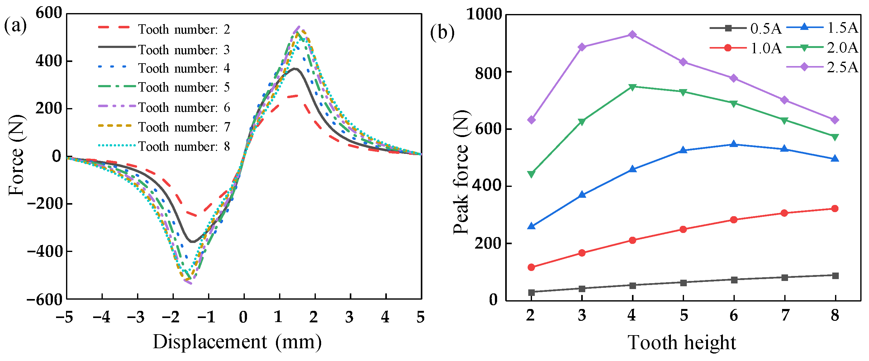
The underlying mechanism of the electromagnetic force of the magnetic-toothed electromagnetic spring is the superposition of the interaction forces between tooth pairs. Therefore, the number of magnetic teeth plays an important role in determining the electromagnetic force characteristics. The number of magnetic teeth was set to be within the range of 2–8 while ensuring that the structural parameters of the teeth remained unchanged (the tooth height = 5 mm and tooth width = 2 mm). Based on the simulation results under a 1.5 A current, the electromagnetic force–displacement curves for different numbers of teeth were recorded, as shown in Figure 10a. At the same time, for a given number of teeth, different currents were used to simulate the electromagnetic force, and the influence of the number of teeth on the maximum electromagnetic force under the different currents is shown in Figure 10b.
It can be seen from Figure 10a that the change in the number of teeth does not significantly affect the position of the maximum electromagnetic force of the magnetic-toothed electromagnetic spring. Additionally, the change in the number of teeth does not affect the effective working range of the electromagnetic spring; once the number of teeth reaches a critical value (in this work, this value is 3), the difference in the electromagnetic force–displacement curve gradually decreases. From Figure 10b, the influence of the number of teeth of TES on the maximum electromagnetic force is affected by the magnitude of the current. When the current is low, increasing the number of teeth can gradually increase the electromagnetic force. However, as the current increases, the effect of increasing the number of teeth on the electromagnetic force first increases and then decreases, with the turning point shifting with the increase in current. The main reason for this phenomenon is the occurrence of magnetic leakage between the magnetic teeth. When the current is low, the total magnetic flux generated by the coil is small; when the number of teeth is small, the total magnetic flux passing through the magnetic teeth at both ends of the electromagnetic spring is high, and its magnetic leakage is rather pronounced. Therefore, the electromagnetic force is relatively small, and the impact of magnetic leakage on the electromagnetic force is the predominant contribution. As the number of teeth increases, the magnetic flux of the electromagnetic spring decreases and the magnetic flux leakage decreases accordingly, so the electromagnetic force increases. However, the magnetoresistance decreases with the increase in the number of teeth, and the influence of the magnetoresistance on the magnetic flux increases gradually, which leads to a decrease in the electromagnetic force. In addition, with the increase in current, the magnetic flux produced by the electromagnetic spring increases for a given number of teeth, and the influence of the magnetic flux leakage on the electromagnetic force decreases gradually, leading to the turning point in the electromagnetic force occurring earlier. Therefore, too many or too few teeth lead to a decline in the performance of the electromagnetic spring.

4.2. Influence of Tooth Height

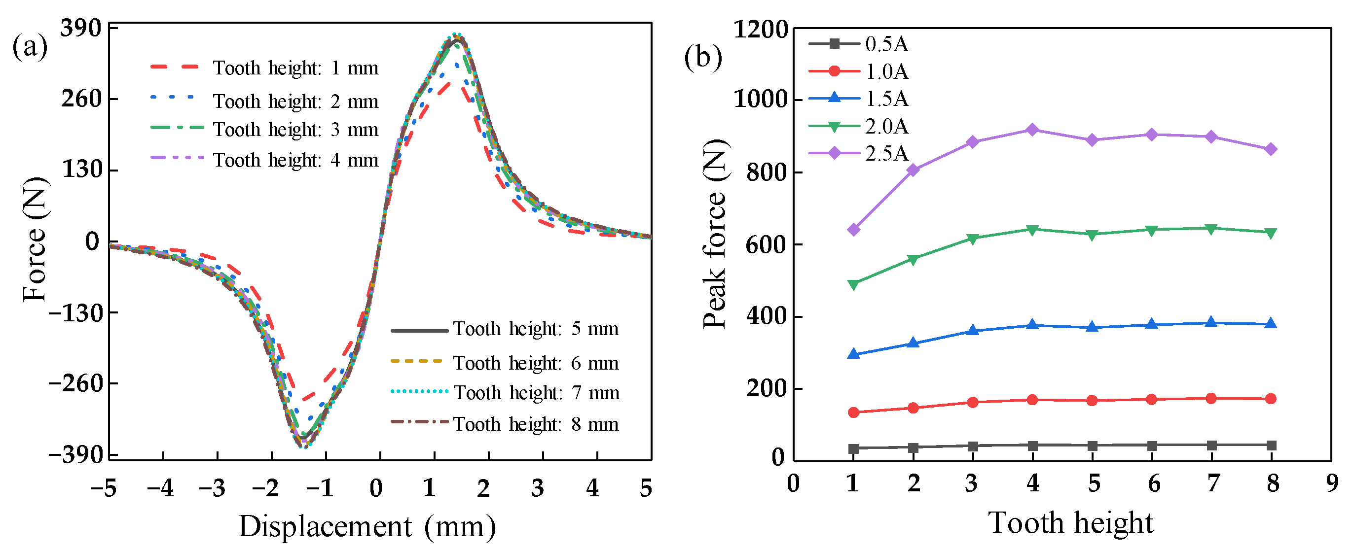
As the magnetic teeth are a key structure for generating electromagnetic force in magnetic-toothed electromagnetic springs, the tooth height also needs to be investigated. Under the condition that the other parameters remain unchanged (the number of teeth = 3, and tooth width = 2 mm), the electromagnetic force characteristics of the electromagnetic spring under different currents are simulated adjusting the tooth height in the range of 1–8 mm. It is worth noting that the air gap should remain unchanged when the tooth height is increased. The electromagnetic force–displacement curve for different tooth heights under a current of 1.5 A was recorded, as shown in Figure 11a. Furthermore, Figure 11b shows the effect of different tooth heights on the maximum electromagnetic force generated by the electromagnetic spring under different currents.
The change in tooth height does not affect the working range of the magnetic-toothed electromagnetic spring, as can be clearly seen in Figure 11a. Additionally, the increase in tooth height does not significantly improve the stiffness of the electromagnetic force–displacement curve. From Figure 11b, as the tooth height increases, the maximum electromagnetic force gradually increases to a critical value and then tends to stabilize. This is because when the tooth height is small, there is more magnetic leakage between the magnetic teeth, resulting in a lower actual magnetic flux passing through the magnetic teeth. Thus, the electromagnetic force generated by the electromagnetic spring is smaller. As the tooth height increases, the magnetic flux becomes more concentrated in the magnetic teeth, which reduces magnetic leakage and increases the magnetic flux through the air gap. Thus, the electromagnetic force generated by the electromagnetic spring increases. However, increasing the tooth height also increases the magnetic resistance of the whole magnetic circuit, resulting in a decrease in the magnetic flux and electromagnetic force. When the tooth height reaches a certain value, the influence of magnetic leakage on the electromagnetic force can be ignored, and the magnetic resistance caused by the increase in tooth height is relatively small, causing the maximum electromagnetic force to stabilize. Therefore, a continuing increase in tooth height has a limited impact on the maximum electromagnetic force.

4.3. Influence of Tooth Width

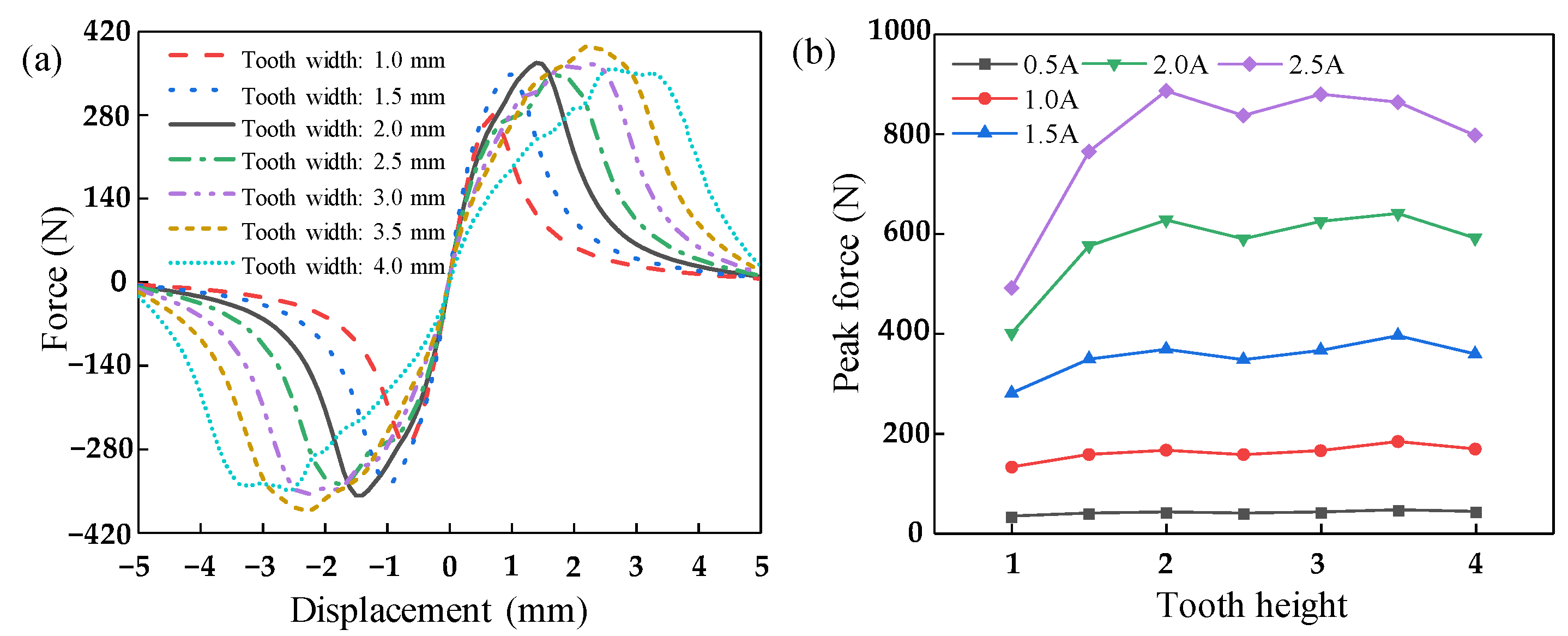
The tooth width is related to the motion displacement of the electromagnetic force, and the electromagnetic force mainly originates from the area where the tooth is directly opposite to each other. Therefore, keeping other structural parameters unchanged (the number of teeth = 3, and tooth height = 2 mm), the influence of the tooth width on the electromagnetic force characteristics is studied in this section by changing the magnetic tooth width from 1 to 4 mm in steps of 0.5 mm, as shown in Figure 12. Figure 12a shows the electromagnetic force–displacement curves for different tooth widths at a current of 1.5 A. Figure 12b presents the maximum electromagnetic force generated by different tooth widths under different currents.
As can be seen from Figure 12a, with the increase in tooth width, the working range of the magnetic-toothed electromagnetic spring also increases. Moreover, when the tooth width increases to a certain value, the linearity of the electromagnetic force–displacement curve decreases. From Figure 12b, as the tooth width increases, the maximum electromagnetic force of the electromagnetic spring increases before fluctuating and finally decreases gradually. The main reason for this phenomenon is that when the tooth width is small, the magnetic resistance and magnetic induction intensity of the magnetic teeth are high. When the current is large, magnetic saturation occurs. As the tooth width increases, the effective magnetic flux through the tooth end increases, resulting in a rapid increase in the electromagnetic force. When the tooth width reaches a critical value, the influence of the magnetic resistance and magnetic circuit saturation generated by the magnetic teeth on the electromagnetic force can be ignored. As the tooth width increases further, some of the magnetic induction is lost to the adjacent magnetic teeth, which is opposite to the direction of the originally generated electromagnetic force, resulting in a decrease in the electromagnetic force. Therefore, the tooth width simultaneously affects the maximum electromagnetic force, linearity characteristics of the electromagnetic force–displacement curve, and effective working range of the magnetic TES.

5. Conclusions

In this work, the finite element model of the TES was established, and the influence of the structural parameters of the magnetic teeth on the performance of the TES was studied based on the established model. The main conclusions are as follows:
(1) A finite element model that can calculate changes in the magnetic field and electromagnetic force was established, and the accuracy of the established model was verified through experiments;
(2) The parameters of the magnetic teeth have a significant impact on the performance of the electromagnetic springs. As the number of teeth increases, the electromagnetic force of the electromagnetic spring first increases and then decreases, and changes in the number of teeth do not affect the effective working range of the electromagnetic spring. As the tooth height or width increases, the maximum electromagnetic force first gradually increases and then tends to stabilize. As the tooth width increases, the working range of the magnetic-toothed electromagnetic spring increases and the maximum electromagnetic force first increases and then tends to stabilize.

Author Contributions

X.Z.: methodology, formal analysis, data curation, investigation, writing—original draft. C.Z.: conceptualization, methodology, supervision, writing—review and editing. Y.L.: conceptualization, methodology, supervision, writing—review and editing. G.X.: conceptualization, methodology, supervision, writing—review and editing. H.B.: supervision, writing—review and editing. All authors have read and agreed to the published version of the manuscript.

Funding

This research was funded by the key technology project of Inner Mongolia (No. 82321160) and the Young and Middle-aged Teachers’ Education and Research Project (Science and Technology) of Fujian Province (No. JAT220016).

Data Availability Statement

The data presented in this study are available upon request from the corresponding author.

Conflicts of Interest

The authors declare no conflict of interest.

References

  1. Liu, Y.; Fu, Y.; He, W.; Hui, Q. Modeling and observer-based vibration control of a flexible spacecraft with external disturbances. IEEE Trans. Ind. Electron. 2019, 66, 8648–8658. [Google Scholar] [CrossRef]
  2. Li, J.Y.; Jing, X.J.; Li, Z.C.; Huang, X.L. Fuzzy adaptive control for nonlinear suspension systems based on a bioinspired reference model with deliberately designed nonlinear damping. IEEE Trans. Ind. Electron. 2019, 66, 8713–8723. [Google Scholar] [CrossRef]
  3. McNeil, S.; Meylan, M.H. Time-dependent modelling of the wave-induced vibration of ice shelves. Mar. Sci. Eng. 2023, 11, 11061191. [Google Scholar] [CrossRef]
  4. Wei, J.; Liu, W.; Gao, P.X.; Ding, Y.J. An analytical dynamic model for vibration suppression of a multi-span continuous bridge by tuned mass dampers. Mar. Sci. Eng. 2023, 11, 11051017. [Google Scholar] [CrossRef]
  5. Carrella, A.; Brennan, M.J.; Kovacic, I.; Waters, T.P. On the force transmissibility of a vibration isolator with quasi-zero-stiffness. J. Sound Vib. 2009, 322, 707–717. [Google Scholar] [CrossRef]
  6. Carrella, A.; Brennan, M.J.; Waters, T.P.; Lopes, V. Force and displacement transmissibility of a nonlinear isolator with high-static-low-dynamic-stiffness. Int. J. Mech. Sci. 2012, 55, 22–29. [Google Scholar] [CrossRef]
  7. Zheng, X.Y.; Wu, Y.W.; Zheng, C.; Bai, H.B.; Liu, R. Quasistatic and low-velocity impact properties of entangled metallic wire material–silicone rubber composite. J. Mater. Res. Technol. 2023, 23, 143–152. [Google Scholar] [CrossRef]
  8. Zheng, X.Y.; Ren, Z.Y.; Bai, H.B.; Wu, Z.B.; Guo, Y.S. Mechanical behavior of entangled metallic wire materials-polyurethane interpenetrating composites. Def. Technol. 2023, 20, 120–136. [Google Scholar] [CrossRef]
  9. Wu, J.L.; Zeng, L.Z.; Han, B.; Zhou, Y.F.; Luo, X.; Li, X.Q.; Chen, X.D.; Jiang, W. Analysis and design of a novel arrayed magnetic spring with high negative stiffness for low-frequency vibration isolation. Int. J. Mech. Sci. 2021, 15, 106980. [Google Scholar] [CrossRef]
  10. Wang, Y.; Li, S.M.; Cheng, C.; Su, Y.Q. Adaptive control of a vehicle-seat-human coupled model using quasi-zero-stiffness vibration isolator as seat suspension. J. Mech. Sci. Technol. 2018, 32, 2973–2985. [Google Scholar] [CrossRef]
  11. Wang, K.; Zhou, J.X.; Chang, Y.P.; Ouyang, H.J.; Xu, D.L.; Yang, Y. A nonlinear ultra-low-frequency vibration isolator with dual quasi-zero-stiffness mechanism. Nonlinear Dyn. 2020, 101, 755–773. [Google Scholar] [CrossRef]
  12. Wu, M.K.; Wu, J.L.; Che, J.X.; Gao, R.Q.; Chen, X.D.; Li, X.Q.; Zeng, L.Z.; Jiang, W. Analysis and experiment of a novel compact magnetic spring with high linear negative stiffness. Mech. Syst. Signal. Process. 2023, 198, 110398. [Google Scholar] [CrossRef]
  13. Zheng, Y.; Li, Q.; Yan, B.; Luo, Y.; Zhang, X. A Stewart isolator with high-static-low-dynamic stiffness struts based on negative stiffness magnetic springs. J. Sound. Vib. 2018, 422, 390–408. [Google Scholar] [CrossRef]
  14. Liu, Y.Q.; Matsuhisa, H.; Utsuno, H. Semi-active vibration isolation system with variable stiffness and damping control. J. Sound Vib. 2008, 313, 16–28. [Google Scholar] [CrossRef]
  15. Pu, H.Y.; Yuan, S.J.; Peng, Y.; Meng, K.; Zhao, J.L.; Xie, R.Q.; Huang, Y.N.; Sun, Y. Multi-layer electromagnetic spring with tunable negative stiffness for semi-active vibration isolation. Mech. Syst. Signal Process. 2019, 121, 942–960. [Google Scholar] [CrossRef]
  16. Carrella, A.; Brennan, M.J.; Waters, T.P.; Shin, K. On the design of a high-static–low-dynamic stiffness isolator using linear mechanical springs and magnets. J. Sound Vib. 2008, 315, 712–720. [Google Scholar] [CrossRef]
  17. Dong, G.; Zhang, X.; Xie, S.; Yan, B.; Luo, Y. Simulated and experimental studies on a high-static-low-dynamic stiffness isolator using magnetic negative stiffness spring. Mech. Syst. Signal Process. 2017, 86, 188–203. [Google Scholar] [CrossRef]
  18. Wu, W.; Chen, X.; Shan, Y. Analysis and experiment of a vibration isolator using a novel magnetic spring with negative stiffness. J. Sound Vib. 2014, 333, 2958–2970. [Google Scholar] [CrossRef]
  19. Zheng, Y.; Zhang, X.; Luo, Y.; Zhang, Y.; Xie, S. Analytical study of a quasi-zero stiffness coupling using a torsion magnetic spring with negative stiffness. Mech. Syst. Signal Process. 2018, 100, 135–151. [Google Scholar] [CrossRef]
  20. Yu, J.; Li, D.; Li, S.; Xiang, Z.; He, Z.; Shang, J.; Wu, Y.; Liu, Y.; Li, R.-W. Electromagnetic vibration energy harvester using magnetic fluid as lubricant and liquid spring. Energy Convers. Manag. 2023, 286, 117030. [Google Scholar] [CrossRef]
  21. Liu, Z.; Wang, X.; Ding, S.; Zhang, R.; McNabb, L. A new concept of speed amplified nonlinear electromagnetic vibration energy harvester through fixed pulley wheel mechanisms and magnetic springs. Mech. Syst. Signal Process. 2019, 126, 305–325. [Google Scholar] [CrossRef]
  22. Zhou, R.; Gao, W.; Liu, W.; Xu, J. Effects of Open-Hole and Reinforcement on the Bearing Performance of the Plain-Woven Fabric Composite I-Section Beams under Shear Load. Aerospace 2022, 9, 537. [Google Scholar] [CrossRef]
  23. Yuan, S.; Sun, Y.; Zhao, J.; Meng, K.; Wang, M.; Pu, H.; Peng, Y.; Luo, J.; Xie, S. A tunable quasi-zero stiffness isolator based on a linear electromagnetic spring. J. Sound Vib. 2020, 482, 115449. [Google Scholar] [CrossRef]
  24. Kallenbach, E.; Kube, H.; Zöppig, V.; Feindt, K.; Hermann, R.; Beyer, F. New polarized electromagnetic actuators as integrated mechatronic components-design and application. Mechatronics 1999, 9, 769–784. [Google Scholar] [CrossRef]
  25. Kim, J. A study on the optimal design and the performance evaluation of electromagnetic energy harvesting device for the rolling stock application. J. Intell. Mater. Syst. Struct. 2020, 31, 2362–2377. [Google Scholar] [CrossRef]
  26. Mahdi, S.M.; Bardaweel, H. Theoretical study and experimental identification of elastic-magnetic vibration isolation system. J. Intell. Mater. Syst. Struct. 2018, 29, 1045389. [Google Scholar]
  27. Olaru, R.; Petrescu, C.; Arcire, A. Design of a magnetic spring for variable stiffness actuators. Proc. Rom. Acad. Sci. Ser. A Math. Phys. Tech. Sci. Inf. Sci. 2021, 2, 235–243. [Google Scholar]
  28. Liu, X.G.; Feng, X.X.; Shi, Y.; Wang, Y.; Shuai, Z.J. Development of a Semi-Active Electromagnetic Vibration Absorber and Its Experimental Study. J. Vib. Acoust. 2013, 135, 151–159. [Google Scholar] [CrossRef]
Figure 1. Structure of the TES.
Aerospace 10 00750 g001
Figure 2. Magnetic circuit simulation model.
Aerospace 10 00750 g002
Figure 3. Grid division result.
Aerospace 10 00750 g003
Figure 4. BH curve of DT4.
Aerospace 10 00750 g004
Figure 5. Distribution of the magnetic flux density of the model spring.
Aerospace 10 00750 g005
Figure 6. Magnetic force line distribution of the model spring.
Aerospace 10 00750 g006
Figure 7. Experimental setup used to measure the static electromagnetic force of the TES.
Aerospace 10 00750 g007
Figure 8. Comparisons of the force–displacement curves of the TES under different currents: (a) 0.5 A, (b) 1.0 A, (c) 1.5 A, (d) 2.0 A, and (e) 2.5 A.
Aerospace 10 00750 g008
Figure 9. Residual curves of the TES under different currents.
Aerospace 10 00750 g009
Figure 10. Electromagnetic force characteristics for different numbers of teeth: (a) electromagnetic force–displacement curve and (b) maximum electromagnetic force under different currents.
Aerospace 10 00750 g010
Figure 11. Electromagnetic force characteristics for different tooth heights: (a) electromagnetic force–displacement curve and (b) maximum electromagnetic force under different currents.
Aerospace 10 00750 g011
Figure 12. Electromagnetic force characteristics for different tooth widths: (a) electromagnetic force–displacement curve and (b) maximum electromagnetic force under different currents.
Aerospace 10 00750 g012
Table 1. Magnetic circuit parameters of the TES.
ParametersCoil Height (mm)Coil Width (mm)Air Gap (mm)Tooth NumberTooth Pitch (mm)
Value32200.25310
Parameters (mm)Tooth HeightTooth WidthStator Shell ThicknessArmature Diameter Shaft Diameter
Value521010020
Table 2. Parameter settings for the grid in each region.
RegionShaftStatorArmatureCoilSolution Domain
Maximum length (mm)1055215
Table 3. The main technical specifications for the experimental system.
EquipmentModelParametersManufacture
Force sensorAR-DN23Range: 0–5 kN
Accuracy: 0.015% F.S
Ailixun, Chian
Displacement sensorML33-12.5-ARange: 0–12.5 mm
Accuracy: 0.1% F.S
Miran, China
Servo electricECMA-C200807SSOutput: 3000 rpmDelta, China
Power supplyDC-3010DRange: 0–10 A, 0–30 VYihua, China
Table 4. Results of the error analysis.
Current (A)RSSTSSR2
0.53.9947 × 1041.8890 × 1060.9788
1.04.8120 × 1052.9294 × 1070.9835
1.54.6403 × 1051.0754 × 1080.9956
2.03.5733 × 1063.2686 × 1080.9890
2.51.0330 × 1074.5877 × 1080.9774
Disclaimer/Publisher’s Note: The statements, opinions and data contained in all publications are solely those of the individual author(s) and contributor(s) and not of MDPI and/or the editor(s). MDPI and/or the editor(s) disclaim responsibility for any injury to people or property resulting from any ideas, methods, instructions or products referred to in the content.