1. Introduction
During high maneuvers of flight vehicles, the attitude angles change drastically with large rotational angular rates. At the same time, there are serious nonlinear coupling problems between rapid changes in aerodynamic and flight dynamic characteristics [
1,
2,
3,
4,
5], which could induce strongly nonlinear, unsteady aerodynamic characteristics and un-commanded multi-degrees-of-freedom coupled motions, endanger flight safety, and even result in the loss of control [
6,
7,
8,
9,
10]. The aerodynamic database for flight control law design is mainly derived from wind tunnel tests. However, the traditional wind tunnel tests based on the linear superposition principle, such as the static test, small-amplitude forced oscillation test, rotary balance test, and so on, separate the interaction between aerodynamic and motion parameters [
11,
12,
13,
14,
15]. These test techniques are difficult to effectively apply in research regarding nonlinear coupling problems of high maneuvers. Therefore, a large number of flight tests have to be performed to reveal nonlinear coupling problems and verify the flight control law of high maneuvers, which are very dangerous, time-consuming, and expensive [
16,
17,
18,
19,
20].
To mitigate the risk and reduce the cost of flight tests, an innovative methodology for wind tunnel tests needs to be developed, which should be able to simulate high maneuvers, investigate nonlinear coupling problems, evaluate flight performances, and verify flight control laws. It can be used as a cost-effective and safe way to perform hardware-in-the-loop tests in the real physical environment of a wind tunnel and bridge the gap between traditional wind tunnel tests and flight tests.
For this purpose, based on maneuver rigs, several innovative methods have been developed to simulate multi-degrees-of-freedom motions during real maneuvers. A three-degrees-of-freedom gimbal with pitch, roll, and yaw motion is used to research aircraft dynamics at conventional and critical flight regimes and validate the control law to prevent stalling and spinning, and it was developed at the Central Aerohydrodynamic Institute (TsAGI) [
21], China Aerodynamics Research and Development Center (CARDC) [
22] and Nanjing University of Aeronautics and Astronautics [
23]. Another three-degrees-of-freedom gimbaled structure with pitch, roll, and yaw motion [
24] for a fin-stabilized, canard-guided projectile was developed at the French-German Research Institute of Saint-Louis (ISL) to verify different flight control approaches for pitch autopilot designs. A four-degrees-of-freedom test rig with pitch, roll, yaw, and heave motion [
25] was developed at Cranfield University to determine the stability and control characteristics of small-scale aircraft. A five-degrees-of-freedom dynamic maneuver rig with pitch, roll, yaw, heave, and sway motion [
26], and a six-degrees-of-freedom maneuver rig with pitch, roll, yaw, heave, sway motion and extended roll motion [
27] was designed at the University of Bristol to perform more extreme aircraft maneuvers and investigate aircraft upset behavior and loss of control in a low-speed wind tunnel. The main disadvantage of the wind tunnel test based on the above typical maneuver rigs is the absence of the direct measurement of aerodynamic forces and moments during motions. Thus, the relationship between aerodynamic and motion parameters cannot be established directly, which is very important for researching and predicting nonlinear coupling problems. Another shortcoming is that all of them are carried out at low speeds and lack the ability to test at high speeds.
To obtain both aerodynamic and motion parameters, a new concept called virtual flight testing (VFT) was first proposed and developed in the Arnold Engineering Development Complex (AEDC) [
28,
29,
30]. It uses an eight-wire system to support an air-to-air missile model in the high-velocity air stream facility, which permits free motion in three rotational degrees of freedom with flight control and also allows the measurement of aerodynamic forces and moments using a balance.
VFT was first developed in the closed test section of a large-scale, high-speed wind tunnel at CARDC. It is more complex and valuable than a similar test in a low-speed wind tunnel [
21,
22,
23,
24,
25,
26,
27], because a wider range of flight speeds can be simulated, and not only motion parameters, but also aerodynamic parameters are measured simultaneously. It is also more difficult to carry out and more accurate than a similar test in an open test section of a wind tunnel, such as AEDC [
28,
29,
30], because the test environment of a closed test section is very different from an open test section in a wind tunnel. A wind tunnel with a closed test section has many space constraints, but the quality of the flow field is much better than that of a wind tunnel with an open test section. In the present work, a new kind of virtual flight testing platform, together with a balance and other sensors, is introduced to realize the free rotational motion and measure the aerodynamic and motion parameters. The main contribution of this paper is the development of a new test platform and the provision of test methods in a high-speed wind tunnel, which can be used to research complex nonlinear coupling problems and evaluate the flight control performance of high maneuvers.
The organization of the paper is as follows:
Section 2 provides an introduction to the VFT platform developed in a high-speed wind tunnel. In
Section 3, the control method of VFT is presented, and the typical test results are shown and analyzed, including a one-degree-of-freedom pitch motion, two-degrees-of-freedom pitch and roll coupled motion, and verification of the pitch and roll decoupled control. The test results of VFT are also compared with flight data of a real pitch maneuver to verify the reliability of VFT. Finally,
Section 4 contains concluding remarks.
2. Virtual Flight Testing Platform
A virtual flight testing platform with three-degrees-of-freedom rotational motions for a missile model was designed and established in the closed test section of a large-scale transonic wind tunnel at CARDC, including pitch motion, roll motion, and yaw motion. The wind tunnel is a semi-circuit, intermittent transonic facility driven by an ejector. The test section of the wind tunnel is 2.4 m × 2.4 m. The Mach number of the wind tunnel is from 0.3 to 1.15. A configuration of the VFT platform with the test model in the closed test section of the wind tunnel is shown in
Figure 1. The main subsystems of the platform are the three-degrees-of-freedom model support, measurement devices of aerodynamic and motion parameters, and a virtual flight control system. A brief introduction of each subsystem and the test model are introduced as follows.
2.1. Three-Degrees-of-Freedom Model Support
The first and most important key issue of VFT is how to support the test model in the test section of the wind tunnel to simulate real maneuvers. Due to the limitation of the space in the closed test section of the current wind tunnel, it is not easy to simulate transitional motion. So a special three-degrees-of-freedom model support was designed to allow for pitch, roll, and yaw motion.
To enable free pitch motion, a crossbeam mounted on two arms together with bearings is used. Then, the test model across the crossbeam is fixed to it to experience free pitch motion. The model support for free pitch motion is illustrated in
Figure 2.
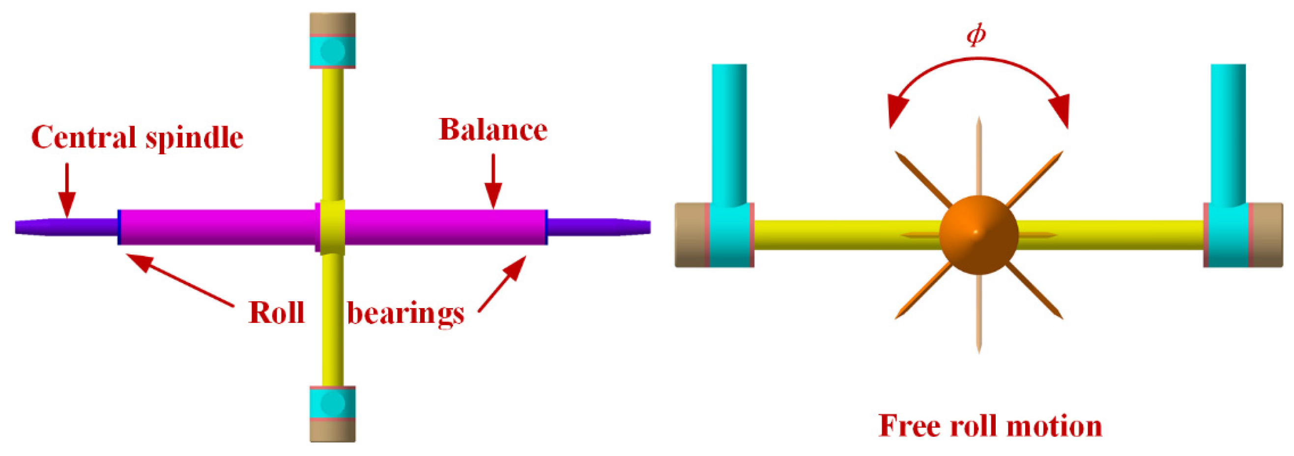
To realize free roll motion, a central spindle across the center of the crossbeam is used. It is installed in the inner space of a five-component strain gauge balance together with bearings. The balance fixed on the crossbeam is designed to measure the normal force, side force, roll moment, pitch moment, and yawing moment of the test model during the test. The test model is connected with the two ends of the central spindle to experience unlimited free roll motion, which is shown in
Figure 3. Two magnetic clutches are used to lock and release pitch and roll motion, which are installed on the crossbeam and the central spindle, respectively.
Due to the limitation of the test section of a wind tunnel, it is unable to simultaneously realize free pitch, roll, and yaw motions. To allow yaw motion, a powerful hydrocylinder equipped on the top and outside of the test section together with a rotation shaft and bearings is used to drive the whole support and test model to realize yaw motion, which is shown in
Figure 4. A closed-loop control law was designed to simulate free yaw motion during real maneuvers, which is based on the yaw moment measured by the balance, and the yaw angle and yaw rate are used as feedback signals.
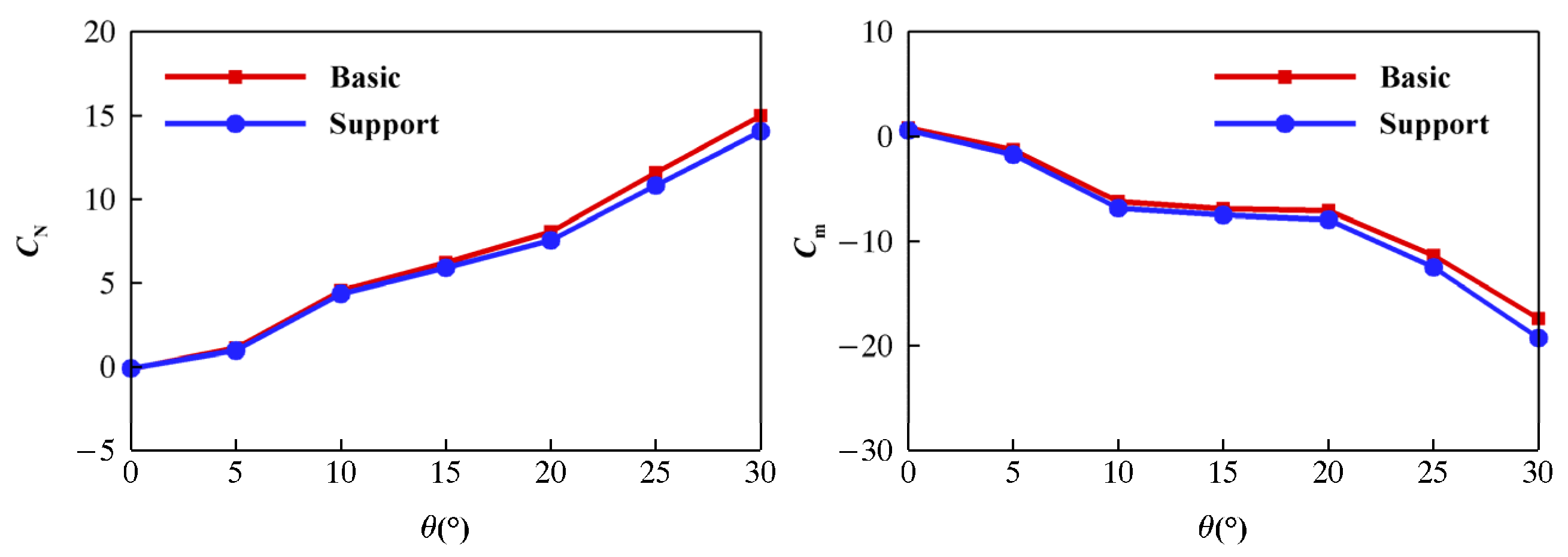
The support interference is always present for the wind tunnel test with a support system. Its effect on aerodynamic forces and moments depends on its structural form and flow field conditions. For the VFT platform, the design of the model support is considered to meet the requirements of structural strength and reduce aerodynamic interference, and is verified by a wind tunnel test and numerical calculations. The current model support has little impact on aerodynamic performance and meets the test requirements. The typical results of support interference for normal force coefficient
CN and pitch moment coefficient
Cm are shown in
Figure 5. The red lines are the results without model support, and the blue lines are the results with model support.
2.2. Measuring Devices of Aerodynamic and Motion Parameters
Traditionally, motion parameters are easy to measure directly during flight. But aerodynamic parameters cannot be measured and are normally identified based on an aerodynamic model from flight data after a flight test. During high maneuvers, aerodynamic and motion characteristics are nonlinearly coupled and affect each other. It is very necessary to real-time synchronously measure aerodynamic and motion parameters, which can reveal complex relationships between them directly. To measure these parameters, three high-resolution photoelectric encoders are installed along the body-axis of the test model to measure the pitch angle, roll angle, and yaw angle. A fiber optic gyroscope is fixed on the inner surface of the model to measure the pitch rate, roll rate, and yaw rate. A slip ring is installed on the central spindle and used to transmit signals of the gyroscope and actuator system. The five-component strain gauge balance is used to measure aerodynamic forces and moments except axis force.
2.3. Virtual Flight Control System
The virtual flight control system outside the wind tunnel was designed to perform flight simulations of the test condition, operate flight control law to deflect control surfaces and simulate real maneuvers, drive the hydrocylinder to realize yaw motion, transmit and receive different signals from encoders, the gyroscope, balance, actuator system, and hydrocylinder, and process and display test data during the test. The function of the virtual flight control system is illustrated in
Figure 6. Unlike the wireless links used in some open test sections of low-speed wind tunnels, the signal transmission is based on a wire link to provide a connection between the measuring devices in the closed test section and the virtual flight control system outside of the wind tunnel. Although it is a more complex and difficult method than a wireless link, the wire link is more stable and reliable. After all, the safety of the VFT platform and the wind tunnel need to be considered first in large-scale, high-speed wind tunnels. The real-time synchronous measurement of the aerodynamic and motion parameters can be achieved based on all these devices and virtual flight control systems during the motions of the test model in the wind tunnel.
2.4. Test Model
The similarity criteria of VFT include geometric similarity, flow similarity, motion similarity, and control similarity. A typical missile model was designed according to these similarity criteria. The test section size of the current high-speed wind tunnel is large enough to allow the geometry size of the test model to be the same as its original real missile. Furthermore, the tail section and actuator system of a real missile can be directly used as part of the test model. Therefore, the performance of the real actuator system can be tested based on a very convenient method provided by VFT. To avoid structural interference, the test model was divided into a front section and rear section to allow the crossbeam to cross its center of gravity and realize free roll motion. The gravity center did not change during the wind tunnel test to simulate the unpowered-flight phase of the missile.
3. Results and Discussion
In order to research the characteristics of open-loop control of a missile model and verify the performance of the different flight control methods, VFT for a one-degree-of-freedom pitch motion for the test model was first conducted. Furthermore, to predict the characteristics of coupled pitch and roll motion and evaluate the performance of decoupled control law, a VFT for two-degrees-of-freedom pitch and roll motion was conducted. The typical results of the VFT are analyzed and discussed as follows.
3.1. One-Degree-of-Freedom Pitch Motion
The open-loop control method and closed-loop control method of VFT and the typical test results of the one-degree-of-freedom pitch motion are first presented in this section.
3.1.1. Open-Loop Control
During one-degree-of-freedom pitch motion with open-loop control, the roll motion is locked by a magnetic clutch, and only pitch motion is released. The commands for control surface deflection are given by the virtual flight control system directly. The typical results of the time histories of the pitch control surface deflection
δz (green line), pitch angle
θ (red line), pitch rate
q (pink line), and normal force coefficient
CN (blue line) are shown in
Figure 7. The control surfaces were successively increased in a stepwise manner from 0° to −10°, and decreased to 0° again. The test model experienced several free pitch oscillations from a trimmed equilibrium to another driven by pitch moment. Thus, the trim characteristics of the test model can be easily obtained for an arbitrary deflection of control surfaces.
The variation in the aerodynamic forces and moments during pitch oscillations can be real-time synchronously measured. It is very important and valuable to investigate nonlinear coupling problems and develop an unsteady aerodynamic model based on the relationship between the aerodynamic and motion parameters established directly by VFT.
3.1.2. Closed-Loop Control
The closed-loop control can be realized based on flight control law with feedback signals. There are two methods to perform closed-loop control of VFT based on the current platform for one-degree-of-freedom pitch motion.
- 1.
Closed-loop control of pitch angle
The first method is the closed-loop control of pitch angle using the attitude measured by the encoder and angular velocity measured by the gyroscope as the feedback signals of the flight control law.
A PID controller is designed based on aerodynamic data of the test model obtained from previous wind tunnel static and dynamic tests, as shown in Equation (1):
where
δz is the pitch control surface deflection angle, in deg.
Kθ1,
Kθ2, and
Kθ3 are the control parameters for the closed-loop control of the pitch angle.
θc is the command of the pitch angle, and
θ is the response of the pitch angle, in deg.
q is the pitch rate, in deg/s.
The flight control law is illustrated in
Figure 8.
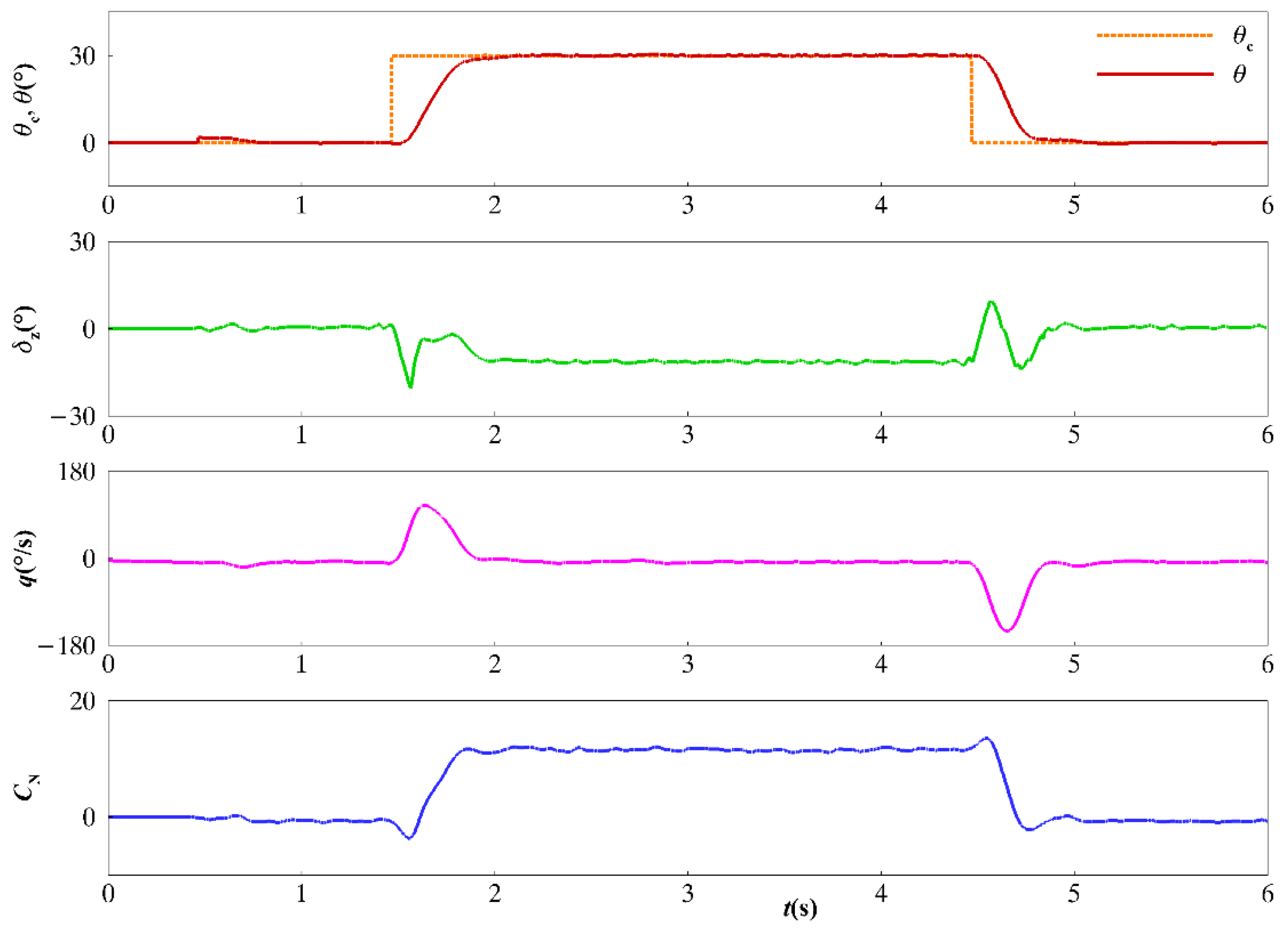
The typical results of one-degree-of-freedom pitch motion with closed-loop control of the pitch angle are shown in
Figure 9. During closed-loop control, the command of the pitch angle
θc (orange line) is given by the virtual flight control system, and the control surfaces
δz (green line) deflect following the flight control law to drive the pitch motion of the test model as expected and achieve the desired pitch angle
θ (red line). The aerodynamic forces and moments, such as
CN (blue line), can also be measured and used to evaluate and optimize the flight control law in the wind tunnel.
- 2.
Closed-Loop Control of Acceleration
Benefitting from the balance, the second method of closed-loop control can be realized, which uses the aerodynamic force measured by the balance and angular velocity from the gyroscope as the feedback signals of the flight control law. The PID controller used for closed-loop control of normal acceleration is shown in Equation (2).
where
Kn1,
Kn2, and
Kn3 are the control parameters for the closed-loop control of normal acceleration.
nzc is the command of normal acceleration, and
nz is the response of normal acceleration, in m/s
2.
Y is the normal force, in N.
m is the mass of the test model, in kg.
The flight control law is illustrated in
Figure 10.
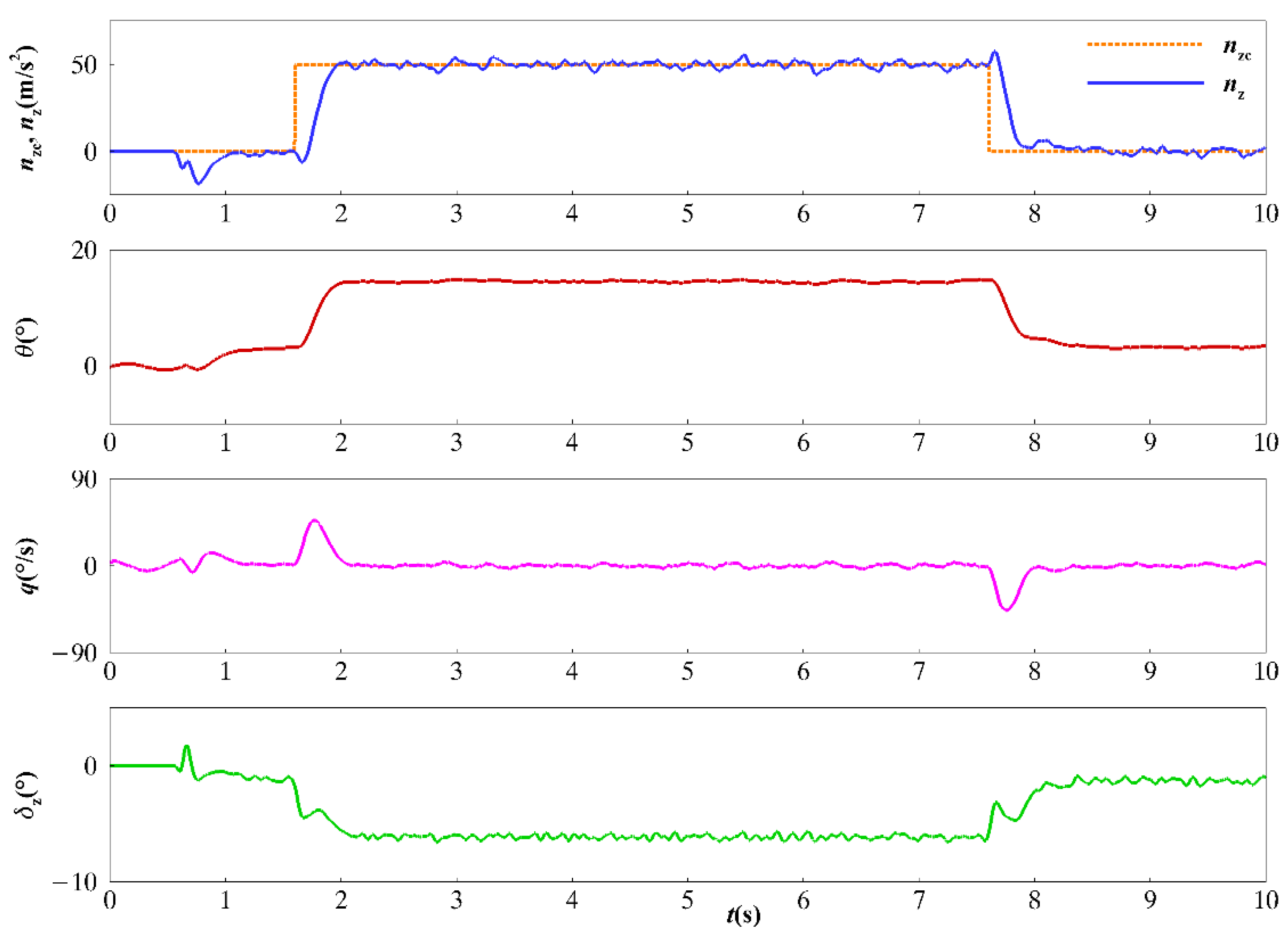
The typical results of one-degree-of-freedom pitch motion with closed-loop control of acceleration are shown in
Figure 11. During closed-loop control of acceleration, the command for normal acceleration
nzc (orange line) is given. The flight control law receives the data of the normal force measured by the balance and gives the command for control surface deflection
δz (green line). The test model is driven by the control surface to an expected normal acceleration
nz (blue line) and pitch angle
θ (red line). This is similar to a real maneuver, which uses acceleration as a command.
3.2. Two-Degrees-of-Freedom Pitch and Roll Motion
3.2.1. Characteristics of Pitch and Roll Coupled Motion
During real maneuvers, there may exist serious coupled motions that can seriously affect flight performance. Based on VFT, the coupled motions and their effects on flight performance can be revealed.
The previous results of wind tunnel static tests provide the change of the roll moment coefficient
Cl as the function of the pitch angle
θ and roll angle
ϕ, which indicates the existence of coupled motion of the test model during a pitch maneuver, as shown in
Figure 12.
The definition of the roll angle
ϕ and its stability
Clϕ are illustrated in
Figure 13. From the result of the roll moment coefficient
Cl as the function of the roll angle
ϕ, the test model was stable at
ϕ = 0°, −90° and 90° due to
Clϕ < 0, but unstable at
ϕ = −45° and 45° due to
Clϕ > 0.
The pressure cloud maps and streamline plots of the typical cross-sections under different pitch angles are shown in
Figure 14. The test model has a slender body and four tail control surfaces. The roll moment coefficient
Cl increases abruptly as the pitch angle
θ beyond 15°. This indicates that there is a significant asymmetrical flow field normally induced by vortices, which affects the control surfaces and induces a significant roll moment. With an increase in the pitch angle, the shed vortices generated from the left and right sides of the slender body gradually moved away from the body and evolved from left-right symmetry to asymmetry. The asymmetrical shed vortices of the slender body affected its downstream control surfaces and formed an asymmetric flow at a different control surface. The asymmetric flow generated a rolling moment and induced a self-excited rolling motion. As the pitch angle continued to increase above 20°, the asymmetric shed vortices moved farther away from the body and control surfaces, causing the rolling moment to decrease.
Based on the prediction from static tests, tests of pitch and roll coupled motions were performed. The typical results are shown in
Figure 15. During the test, the pitch motion and roll motion were released at the same time. Then the test model experienced pitch motion with closed-loop control and roll motion with open-loop control. The test model pitched up very quickly following the flight control law and reached the desired position (red line). The variation in the roll angle
ϕ and its effect on the pitch motion were very small during the pitch-up motion, but became serious when the test model tried to maintain the pitch position at a high angle of attack (blue line). The maximum roll rate was near 400°/s. The pitch angle
θ also varied due to the effect of the roll motion. And the deflection of the control surfaces
δz (red line) was in chaos. The roll oscillation proves the prediction based on the static test shown in
Figure 12. The significant increase in the side force coefficient in
Figure 15 appears as the pitch angle increases, which also indicates the existence of an asymmetric vortex flow. When the test model pitched down, the roll angle changed to oscillate around
ϕ = −90°, which is a stable point, as shown in
Figure 13.
The phase diagrams of pitch motion in the (
θ,
q) plane and roll motion in the (
ϕ,
p) plane are shown in
Figure 16. These indicate that the pitch motion and roll motion at high angles of attack are similar to limited cycle oscillation (LCO). And two stable points of roll motion are clearly displayed.
3.2.2. Decoupled Control of Pitch and Roll Motion
To realize a pitch maneuver, a flight control law that suppresses roll motion to first reduce the coupled effect on pitch motion was attempted. The PID controller of pitch motion is the same as Equation (1). The PID controller of roll motion is shown in Equation (3), and the command of the roll angle is 0° to suppress the roll motion.
where
δx is the roll control surface deflection angle, in deg.
Kϕ1,
Kϕ2, and
Kϕ3 are the control parameters for closed-loop control of the roll angle.
ϕc is the command for the roll angle, and
ϕ is the response of the roll angle, in deg.
p is the roll rate, in deg/s.
The closed-loop control of the roll angle uses the roll angle from the encoder and roll rate from the gyroscope as the feedback signals of the flight control law, which is illustrated in
Figure 17.
The typical results of the decoupled control of pitch and roll motion are shown in
Figure 18. Compared to the results of the pitch and roll coupled motion shown in
Figure 15, it is evident that the roll motion (blue line) was suppressed successfully during the test, and the pitch maneuver (red line) was achieved following the flight control law. The variation in the side force coefficient was also very small during the test. The deflection of the control surfaces is regular and similar to the deflection in
Figure 8. So, based on VFT, the potential coupled motion can be revealed, and the more efficient and suitable flight control law for decupled control can be evaluated.
3.3. Comparison with Flight Data
The typical test results shown above indicate that VFT is very useful for investigating complex coupling problems and verifying flight control performance. However, there are some differences between VFT and real maneuvers due to some limitations in the wind tunnel. Consider a three-degrees-of-freedom pitch motion in the vertical plane
Ogxgzg, which includes translational motion and rotational motion, as illustrated in
Figure 19.
The equations of pitch motion for a real maneuver are as follows:
where
V is the airspeed, in m/s;
Q is the dynamic pressure, in Pa;
L is the reference length, in m;
S is the reference area, in m
2;
Iy is the moment of inertia in pitch, in kg/m
2; and
g is the gravity acceleration, in m/s
2.
A is the angle of attack, in rad,
θ is the pitch angle, in rad and
q is the pitch rate, in rad/s.
CA is the axis force coefficient,
CN is the normal force coefficient, and
Cm is the pitch moment coefficient.
CT is the thrust force coefficient. When the engine of the missile is not started or turned off,
CT is equal to zero.
xg is the longitudinal coordinate in the earth-fixed system, in m, and
zg is the normal coordinate in the earth-fixed system, in m.
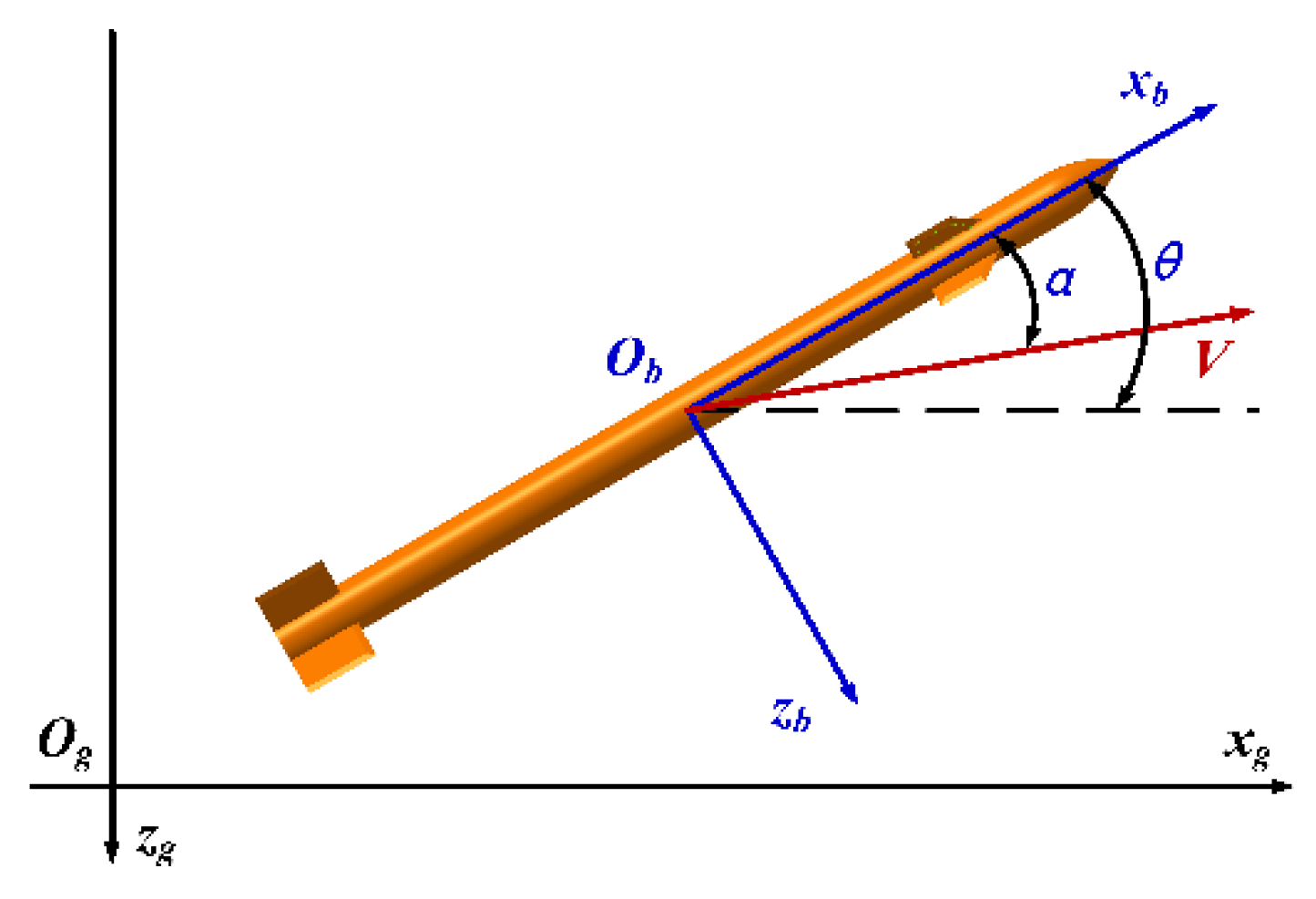
For VFT, the pitch motion reduces to one-degree-of-freedom due to the constraint of translational motion, and the airflow speed generally does not change during a test, as illustrated in
Figure 20.
The equations for the pitch motion of VFT are as follows:
There are two main differences between VFT and real maneuvers, which are constrained translational motion and changes in speed. For the current VFT, it is unable to simulate translational motion. The velocity cannot be continuously changed very quickly, like a real maneuver, and the airflow speed in a wind tunnel can only vary step by step to simulate the whole variation change in the velocity of a real maneuver.
The typical test results of closed-loop control of acceleration for different airflow speeds are presented in
Figure 21, together with the flight data of a real maneuver. During the real maneuver, the command for normal acceleration was given, and the missile experienced pitch maneuvers with closed-loop control. The Mach number changed from 0.90 to 0.75, and the flight altitude changed very little. In order to simulate a real maneuver, the typical Mach numbers 0.90, 0.80, and 0.75 were applied in VFT. For each Mach number of the VFT, the dynamic pressure was consistent with the real maneuver at the state of the same Mach number.
Compared to the real maneuver, the time history and equilibrium position of normal acceleration, angle of attack, and control surface were very close to the flight data. And furthermore, changes in the aerodynamic force and moments during VFT are obtained directly, and they cannot be easily obtained during a real maneuver. This is one of the significant advantages of VFT. Of course, there are some differences between VFT and real maneuvers. The reason is that for real maneuvers, the velocity continuously decreases during the pitch-up motion, so the angle of attack must increase continuously to meet the requirement of the commanded normal acceleration. Therefore, the control surfaces must deflect continuously to increase the angle of attack. Since the airflow speed in wind tunnels is nearly constant during a test, the angle of attack and deflection of control surfaces do not change when the normal acceleration reaches the constant commanded value. The difference in the pitch rate is due to the flight path angle of a real maneuver, which is always zero for VFT due to the constraint translation motion. Nonetheless, changing the airspeed step by step in VFT can provide a much more realistic and useful environment to simulate and investigate real maneuvers than traditional wind tunnel tests.
4. Conclusions
A virtual flight testing platform has been developed for a large-scale, high-speed wind tunnel, which is composed of three-degrees-of-freedom model support, measuring devices for the aerodynamic and motion parameters, a virtual flight control system, and a test model. The current VFT provides a physical environment and innovative methodology, and can realistically simulate real maneuvers and real-time synchronously measure aerodynamic and motion parameters. It provides the ability to investigate the coupling characteristics of unsteady aerodynamics and nonlinear flight dynamics, evaluate flight performance, and verify the flight control law, which could significantly mitigate risk and reduce the cost of subsequent flight tests.
Different kinds of tests have been carried out to illustrate the capabilities of VFT, including one-degree-of-freedom pitch motion and two-degrees-of-freedom pitch and roll motion with open-loop control and closed-loop control. The two methods of closed-loop control with feedback signals from the encoder or balance were demonstrated. The serious pitch and roll coupled motion at a high angle of attack was revealed. The flight control law that suppresses roll motion firstly to reduce the coupled effect on pitch motion was successfully verified. Although there are differences between VFT and real maneuvers, the comparison of the test results and flight data proves the reliability and capability of VFT. Furthermore, the relationship between the aerodynamic and motion parameters directly established by VFT can be used to develop a more accurate unsteady aerodynamic model and flight simulation model in the future.


