1. Introduction
The quadrotor suspension system is a versatile technology with diverse applications [
1,
2], including freight transport [
3,
4,
5,
6], agriculture, forestry, crop protection, and environmental sensing [
7]. This system is highly regarded for its exceptional flight flexibility, cost effectiveness, and ease of loading and unloading [
8,
9,
10,
11]. Nevertheless, single quadrotor suspension systems have their inherent limitations, characterized by a constrained load capacity and diminished efficiency when dealing with expansive areas or multiple loads [
12,
13]. To surmount these limitations, the adoption of multi-quadrotor suspension systems is gaining momentum. Cooperative formation control has emerged as an enticing solution across various sectors, such as transportation and detection, capturing substantial interest among researchers [
14,
15,
16,
17,
18]. This approach harnesses the combined capabilities of multiple quadrotors, elevating their performance and efficiency across an extensive spectrum of applications.
While there has been substantial research into the control of single quadrotor suspension systems [
11,
19,
20,
21,
22,
23,
24,
25,
26], many of these methods exhibit limitations. Much of the existing research predominantly concentrates either on the load [
19,
20,
21] or solely on the quadrotor [
11,
22,
23]. Although this specialized approach ensures effective control of the individual component being studied, it often sacrifices the overall system’s dynamics. This can lead to undesirable outcomes such as horizontal position oscillations of the quadrotor or significant swings in the suspended load [
24,
25,
26]. To address these issues comprehensively, there is a pressing need for integrated control strategies that simultaneously consider both the quadrotor and the suspended load. This approach aims to optimize the performance and stability of the entire system.
Multi-quadrotor suspension systems operating in coordinated formations offer several advantages, including enhanced mission efficiency, extended operational reach, and the capacity to establish networks for task execution [
27]. Various formation control methods govern these systems, each with its unique strengths and approaches. Prominent among these methods are the Leader–Follower Method [
28], which designates a leader quadrotor to guide the formation, albeit with potential limitations on flexibility. The Virtual Structure Method [
29] introduces a virtual framework within the formation, allowing for the maintenance of desired relative positions while affording greater formation geometry flexibility. The Behavior-Based Method [
30] empowers each quadrotor to exhibit specific behaviors within the formation, enhancing adaptability to dynamic environments. The Graph Theory-Based Method [
31] leverages graph theory to model communication relationships among quadrotors, transforming formation control challenges into consistency and system stability problems. In recent years, there has been a notable upsurge in research centered on graph theory-based methods. These techniques, by representing communication relationships as edges in a graph, provide a potent framework for modeling multi-quadrotor systems. Through matrix transformations, they facilitate the conversion of formation control challenges into consistency and system stability problems, thereby enhancing the precision and adaptability of multi-quadrotor formation control strategies.
Consistency theory, firmly rooted in graph theory-based methodologies, stands as a fundamental concept within the domain of multi-quadrotor formation control. Its primary objective revolves around the assurance that quadrotors, operating within a formation, maintain a steadfast and unchanging relative spatial configuration as they navigate in perfect harmony and synchrony [
32]. This theory assumes a central role in safeguarding the intended formation shape and preserving the relative positions of quadrotors. Consequently, it fortifies the overarching unity and stability of the formation. The bedrock of consistency theory lies in the cultivation of synchronized motion and seamless coordination among quadrotors. As a result, it profoundly enhances the efficiency and effectiveness of multi-quadrotor systems across a diverse spectrum of applications [
33].
Reference [
34] introduces a novel consistent formation control algorithm based on the super-twisting algorithm, notable for its robustness and effectiveness in addressing parameter uncertainties. Reference [
35] combines sliding mode control and consistency theory to suppress time-varying disturbances in the position loop, ensuring that quadrotors adhere closely to desired trajectories while maintaining a fixed formation. Reference [
36] tackles consistent formation control in discrete time, employing system identification techniques to obtain dynamic models for altitude, horizontal, and yaw motions of quadrotors. A consistent formation controller is designed using the Riccati equation and parameter uncertainty theorem to ensure the stable flight of multi-quadrotor formations. In contrast to the extensive research on consistent formation control of quadrotors, the field of formation flight involving quadrotor suspension systems remains relatively unexplored. Recognizing the quadrotor as the central element of the system, we propose the application of established consistent formation control techniques to quadrotor suspension systems. This extension opens new possibilities for achieving precise and coordinated control within multi-quadrotor suspension setups.
Compared to traditional quadrotor formation flight control, achieving formation with a quadrotor suspension system introduces heightened complexity and challenges [
37,
38,
39]. This complexity arises from various factors, including the mutual influence between the horizontal position of the quadrotor and the oscillations of the suspended load. The introduction of two additional degrees of freedom associated with the load’s swing angles necessitates innovative underdrive system control schemes. Furthermore, effective control must manage load oscillations to prevent collisions between adjacent loads. In cooperative formation control, the unique characteristics of cable-suspended loads mandate separate handling of the horizontal direction and longitudinal height. In summary, achieving cooperative formation control in quadrotor suspension systems poses a formidable challenge due to its highly coupled, under-driven, and complex nonlinear nature. Innovative control strategies and approaches are imperative to address these challenges effectively.
Recognizing the intricate nature of quadrotor suspension systems and building upon the foundational insights from previous research that have underpinned the control of individual quadrotor suspension systems [
40,
41,
42], and drawing inspiration from the field of quadrotor formation control, this paper introduces an innovative cooperative control methodology firmly rooted in the principles of consistency theory. The primary contributions and unique aspects of this study are outlined as follows:
Formation Control with a Virtual Leader: In response to the intricacies inherent to the operation of quadrotor suspension systems, this research introduces a novel formation controller, strategically incorporating a virtual leader. Deliberately designed to address both the horizontal and vertical aspects of the system, this controller places a primary emphasis on preserving the coherency of quadrotor relative positions. Notably, the design enhances the anticipated relative distances among quadrotors, effectively reducing the potential for collisions and, consequently, promoting a heightened degree of safety and synchronization within the formation.
Integrated Control for Position, Attitude, and Swing Angles: A sophisticated control strategy is meticulously devised to govern the position, attitude, and swing angles within the quadrotor suspension system. This intricate control paradigm harnesses the seamless integration of three pivotal components: the position controller, the swing angle controller, and the attitude controller. Notably, the control of swing angles in the suspension system is achieved by translating output signals from the position and swing angle controllers into inputs for the attitude controller. This holistic methodology ensures the precise tracking of quadrotor trajectories while mitigating the oscillations induced by load dynamics.
Integral Type Backstepping Sliding Mode Controller: To address the challenge posed by oscillations in the position of quadrotors induced by suspended loads, an integral-type backstepping sliding mode controller is introduced. This controller offers a resilient solution to mitigate oscillations through the skillful integration of integral control techniques within the backstepping sliding mode framework. An innovative adaptation involves substituting the conventional sign function with the hyperbolic tangent function. This alteration not only minimizes jitter in controller outputs, but also fortifies the overall robustness of the system, resulting in enhanced performance and reliability.
In summary, this paper introduces a comprehensive cooperative control framework for quadrotor suspension systems, grounded in consistency theory. The novel contributions include formation control with a virtual leader to maintain relative position coherence, an integrated control strategy covering position, attitude, and swing angles, and the implementation of an integral-type backstepping sliding mode controller with a hyperbolic tangent function for improved stability and robustness. Collectively, these innovations expand the frontiers of cooperative control for quadrotor suspension systems, tackling their inherent complexities, and laying the groundwork for more effective and reliable operations.
The specific chapters are organized as follows.
Section 2 presents the dynamic modeling of the quadrotor suspension system.
Section 3 shows the cooperative formation controller design and stability proof.
Section 4 presents the experimental simulation results to verify the designed control scheme.
Section 5 concludes the paper.
2. Quadrotor Suspension System Dynamic
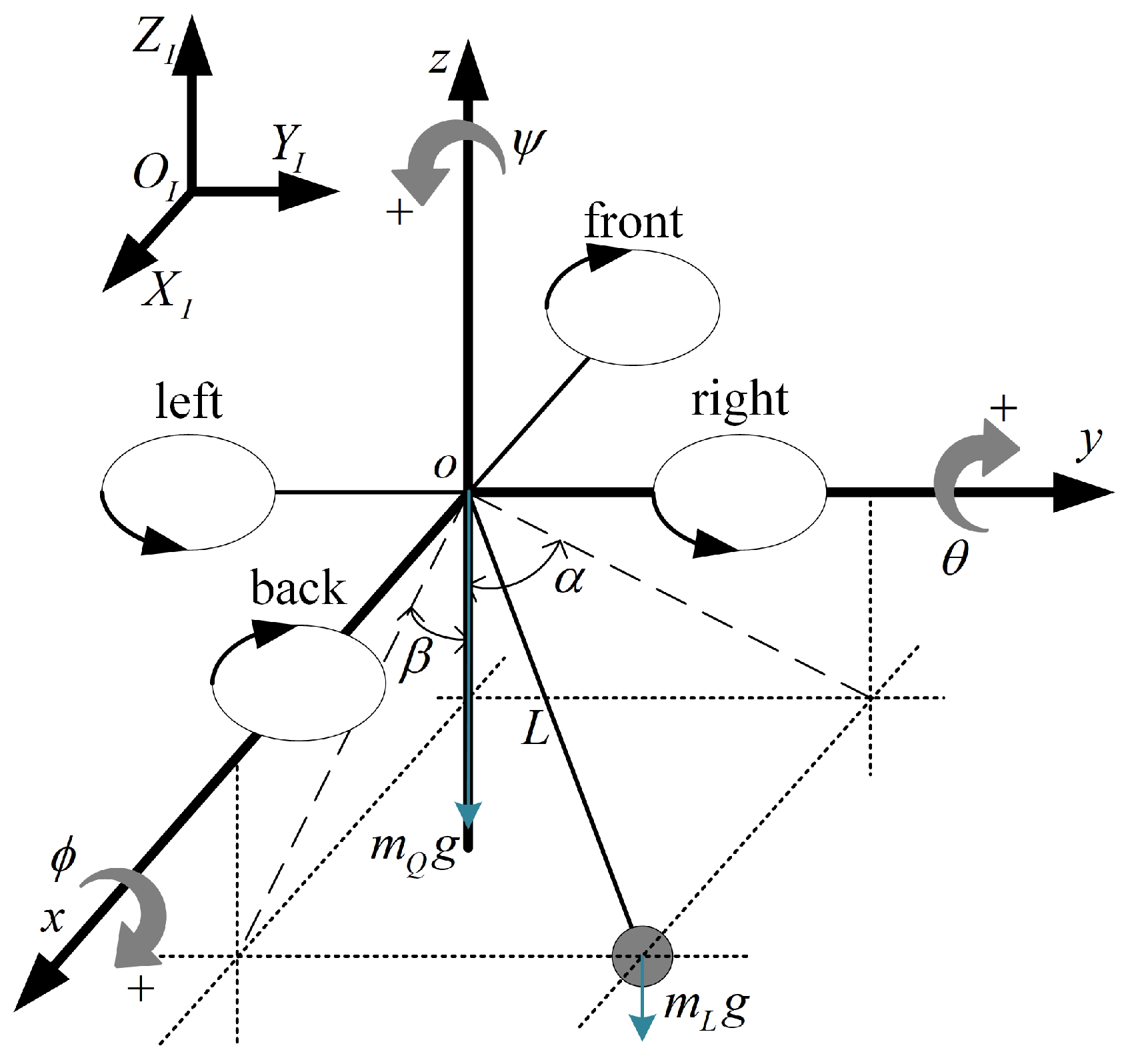
The quadrotor suspension system includes a quadrotor body with six degrees of freedom and a suspended load with two degrees of freedom, which cannot simply be treated as the drive of the load or the load as a disturbance to the quadrotor, so a new quadrotor suspension system model must be established. The model is shown in
Figure 1.
In
Figure 1, a common cross-type quadrotor is shown, defining the inertial coordinate system
. The center of mass of the quadrotor is considered as the origin of the quadrotor body coordinate system [
5],
x points in the direction of the tail of the aircraft,
y points to the right of the aircraft, the
z vertical
plane points above the aircraft body,
is the angle between the cable and the
plane,
is the angle between the cable and the
plane, and the cable length is
L. The conversion of inertial and airframe coordinate systems is described by Euler angles, the rotation around the
x-axis is the roll angle
, the rotation around the
y-axis is the pitch angle
, the rotation around the
z-axis is the yaw angle
. The rotation matrix is
where s means sin and c means cos.
We define the position of the quadrotor as , the attitude of the quadrotor as , the swing angle of the load as . The cable attachment point is considered to be the center of mass of the quadrotor, and the cable is considered to be tight at all times. Considering that the load is always under the quadrotor, that is, .
The system is driven by a quadrotor motor, the rotor generates lift
and reaction-torque
,
, and the control signal
is
Since the load cable is assumed to be tied to the quadrotor’s center of mass, the load is assumed to have no effect on the quadrotor’s attitude angle, so we model the attitude dynamics using the Newton–Euler equation.
where
is the rotational inertia and
is the attitude angular velocity. Using the principle of small-angle approximation, we let
,
is external moments,
l is the quadrotor arm length.
The positions of the quadrotor and the swing angle are coupled, so we use the Euler–Lagrange function to model the dynamics.
The position of the load
can be obtained from the quadrotor position and the swing angle, with cable length
where
.
The Euler–Lagrange function is as follows, and
,
where
is system kinetics composed of quadrotor kinetic energy
and load kinetic energy
,
is the potential energy of the system.
The kinetic energy of the system is
where
,
are quadrotor and load mass.
System potential energy is
We obtain the Euler–Lagrange equations for system
where
is the internal and external forces and moments on the system, and
,
. Substituting
, we can obtain the quadrotor suspension system position and the swing angle model.
In summary, we can obtain the dynamics model of the quadrotor suspension system.
where
,
,
.
3. Cooperative Formation Controller Design
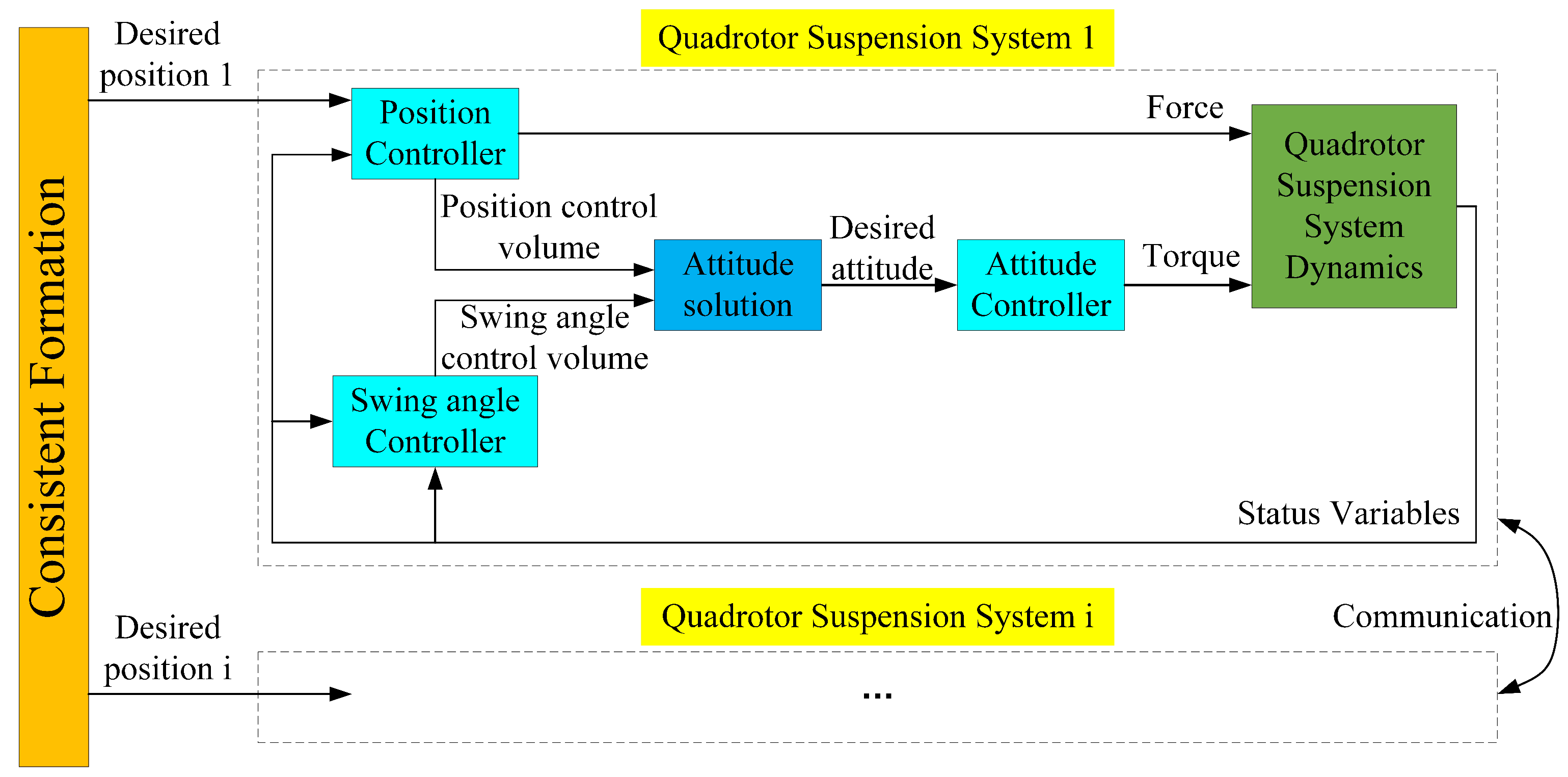
The cooperative formation controller in this paper is divided into a trajectory generation part based on consistency theory and a nonlinear controller part based on integral type backstepping sliding mode, and the control block diagram is shown in
Figure 2.
In
Figure 2, the desired trajectory for each quadrotor is computed using the first-order consistent formation system, employing virtual piloting. The control parameters
,
,
, and
are derived from both the position controller and the swing angle controller. Notably, for the attitude solution, the influence of roll and pitch on position is disregarded, that is,
. The desired attitude is obtained, and the force and moment of the system are obtained by the attitude angle controller and position controller to realize the trajectory tracking control of the quadrotor suspension system.
The control structure designed in this paper has the advantage of converting the control quantity of the swing angle controller to the attitude control input, thus avoiding the problem of start failure caused by the conversion to the position control input, and at the same time realizing the accurate control of the quadrotor position and the swing reduction control of the suspended load.
3.1. Collaborative Trajectory Generation
In the context of ensuring the consistent formation control of multi-quadrotor suspension systems, a fundamental understanding of algebraic graph theory is indispensable. Let us define an oriented graph , where the vertex set is denoted as , representing a collection of n nodes, and the edge set is , signifying the adjacency relationships between these nodes. The index set for the nodes is denoted as . To describe the communication relationships among the nodes, we introduce the adjacency matrix . Here, the element takes on the value to indicate that node j can receive information from node i, while signifies the absence of such information flow. Furthermore, the Laplacian matrix of G is defined as , with diagonal elements and off-diagonal elements .
Theorem 1 ([
43]).
For a communication structure directed graph G consisting of n intelligent agents, a sufficient necessary condition for this system to converge to average consistency, which means that the states or behaviors of these agents collectively tend to reach a specific consistent state or value, is that graph G is a strongly connected equilibrium graph or a connected undirected graph. The first-order consistent formation control algorithm with navigator designed in this paper, i.e., the consistency of the quadrotor positions, thus considers the agents as single-integral systems with the equation of state
where
is the position state of agent
i, and
is the control input.
Theorem 2 ([
43]).
In any initial state, the control algorithm enables the multi-agent system (10) to satisfyThen, the multi-intelligent body system (10) is said to be able to achieve asymptotic consistency. The design consistency formation algorithm is
where
h denotes the communication relationship between the virtual navigator and the follower,
is the ability of the follower to receive information from the navigator,
is the deviation matrix related to system formation, and
is the position state of the navigator. From Theorem 2, it can be seen that the designed algorithm can make the intelligent body agree while maintaining the relative distance from the navigator.
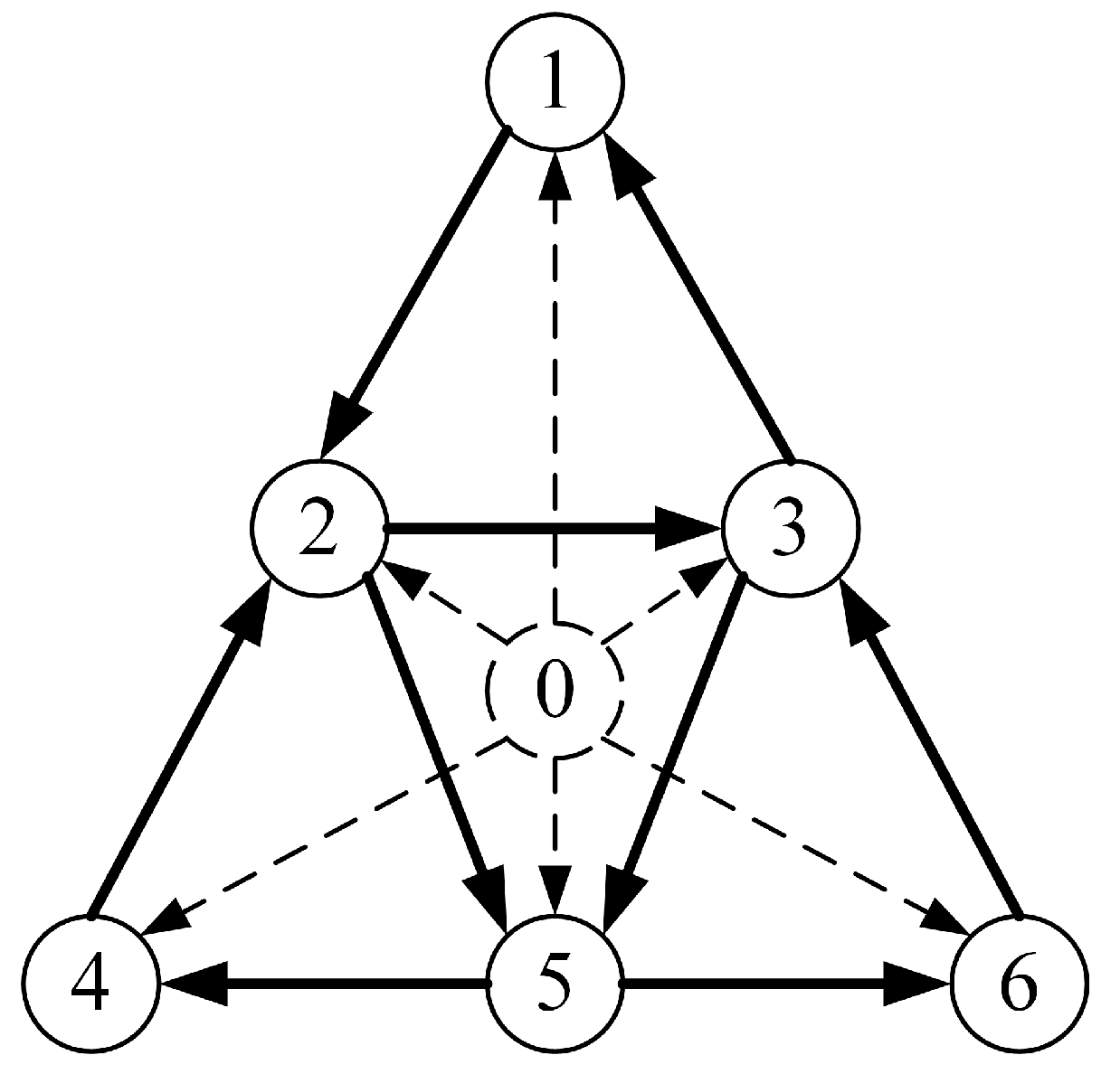
We propose a virtual pilot and six quadrotor followers. Each follower can obtain the information of the pilot, and the directed communication topology is shown in
Figure 3.
The communication graph in
Figure 3 is a strongly connected graph containing a directed spanning tree. The adjacency matrix is
, the Laplacian matrix is
From Theorem 1, the system is consistent.
3.2. Controller Design
The controller design of the quadrotor suspension system is divided into three modules: quadrotor attitude, quadrotor position, and suspension swing angle, where attitude is the inner loop and position and suspension swing angle are the outer loop. In the following, , , , and are all constants greater than zero. First, the integral type backstepping controller is designed. We take the roll angle as an example.
Step 1: Define the error
where
is the desired roll angle, deriving Equation (
13) and obtaining the error of the roll angle velocity
where
is the virtual input volume.
Step 2: Design the Lyapunov function of
:
The derivative is obtained as
Take as the virtual control input, i.e., the actual roll speed, and define its expected value as to make ; let .
Step 3: Add an integration term to the desired virtual input to increase robustness and reduce error:
where
.
Step 4: Define the virtual input error
Substituting in
, we obtain
The derivative of (
18) can be obtained as
where
is a roll angle acceleration model. It can be obtained from (
19),
To make , it is also needed to make , tend to zero.
Step 5: Design Lyapunov functions for
,
,
:
Substitute (
20) and (
21) into (
23):
To make
, design the control variable
as
The proof of the stability of the integral type backstepping controller is as follows:
Proof. Taking
into (
24), we can obtain
It can be concluded that the designed control law is asymptotically stable. □
Similarly, the control laws for pitch angle and yaw angle can be obtained, along with stability proof.
where
,
represent the desired pitch angle and yaw angle, respectively, and
Similarly, the swing angle controller is designed in the same manner.
where
and
are the desired values, and the definitions of each variable that appear are as follows:
,
.
The position of the quadrotor is susceptible to disturbances and load. Therefore, an integral backstepping sliding mode controller is designed by combining sliding mode control with backstepping control to address this issue. Taking the altitude z of the quadrotor as an example, the first four steps are the same as mentioned above.
Step 1: Define the error term and the virtual input .
Step 2: Design a Lyapunov function for the error term such that the desired virtual input is .
Step 3: Add an integral term to the function , .
Step 4: Define the error term for the virtual input .
Step 5: Based on the integral backstepping method, add sliding mode control and define the sliding surface.
Taking the derivative of
,
Step 6: Design Lyapunov functions for
,
,
:
Taking the derivative of (
32),
To make the controller stable and reduce chattering in sliding mode control, use the hyperbolic tangent function instead of the sign function and design the control law.
is the sliding mode switching gain.
The proof of the stability of the integral backstepping sliding mode controller is as follows:
Proof. Substituting (
34) into (
33),
We let
Q be a positive definite matrix.
The determinant of
Q is positive, which means the control parameters need to satisfy
. We can obtain
We substitute into (
35)
Therefore, it can be proved that the control system is stable. □
Similarly, horizontal position controllers and swing angle controllers can be designed. It should be noted that the horizontal position controller does not directly obtain the desired roll and pitch angles, but obtains the desired rotation matrix, that is,
, to avoid the calculation of inverse sine and greatly reduce the computational complexity. The design process and stability analysis are not repeated here, and the results are obtained.
where
and
are the desired values, and the definitions of each variable that appear are as follows:
,
.
4. Simulation Results
This paper employs Simulink simulation experiments to validate the proposed control scheme. The model parameters for the quadrotor suspension system are shown in
Table 1.
The initial positions of the six quadrotors are
, with position deviation matrix
. The trajectory of the virtual leader is
,
, with the first 10 s being the rising stage. The control system parameters are shown in
Table 2.
The following are the results of the simulation experiments.
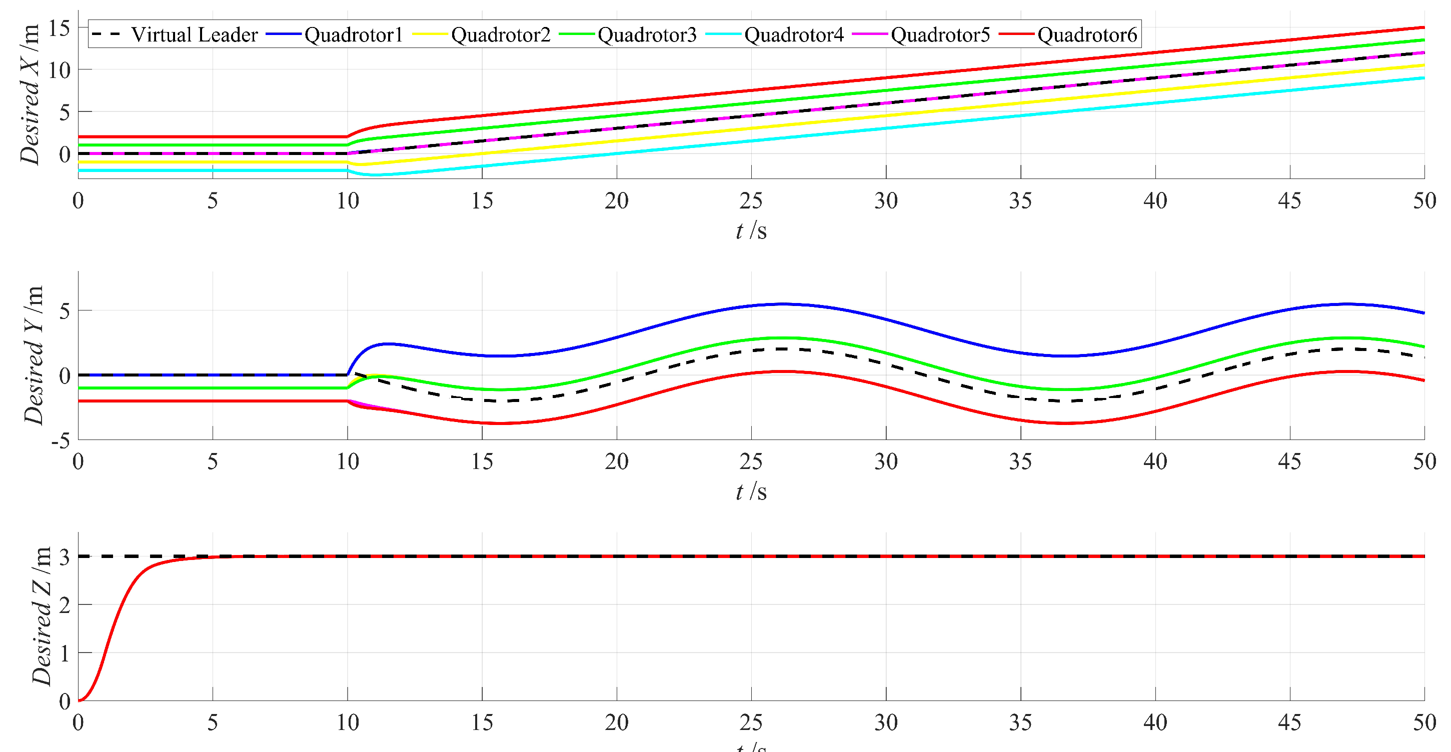
The expected trajectory of the quadrotor generated by the consensus formation algorithm shown in
Figure 4. It can be observed from the figure that the designed formation algorithm can effectively complete the formation task under the guidance of the virtual leader, generating a formation trajectory that brings the quadrotors’ horizontal and vertical positions from the initial position to the expected formation trajectory. Additionally, the algorithm forms the corresponding formation according to the designed deviation matrix and maintains consistency among the quadrotors.
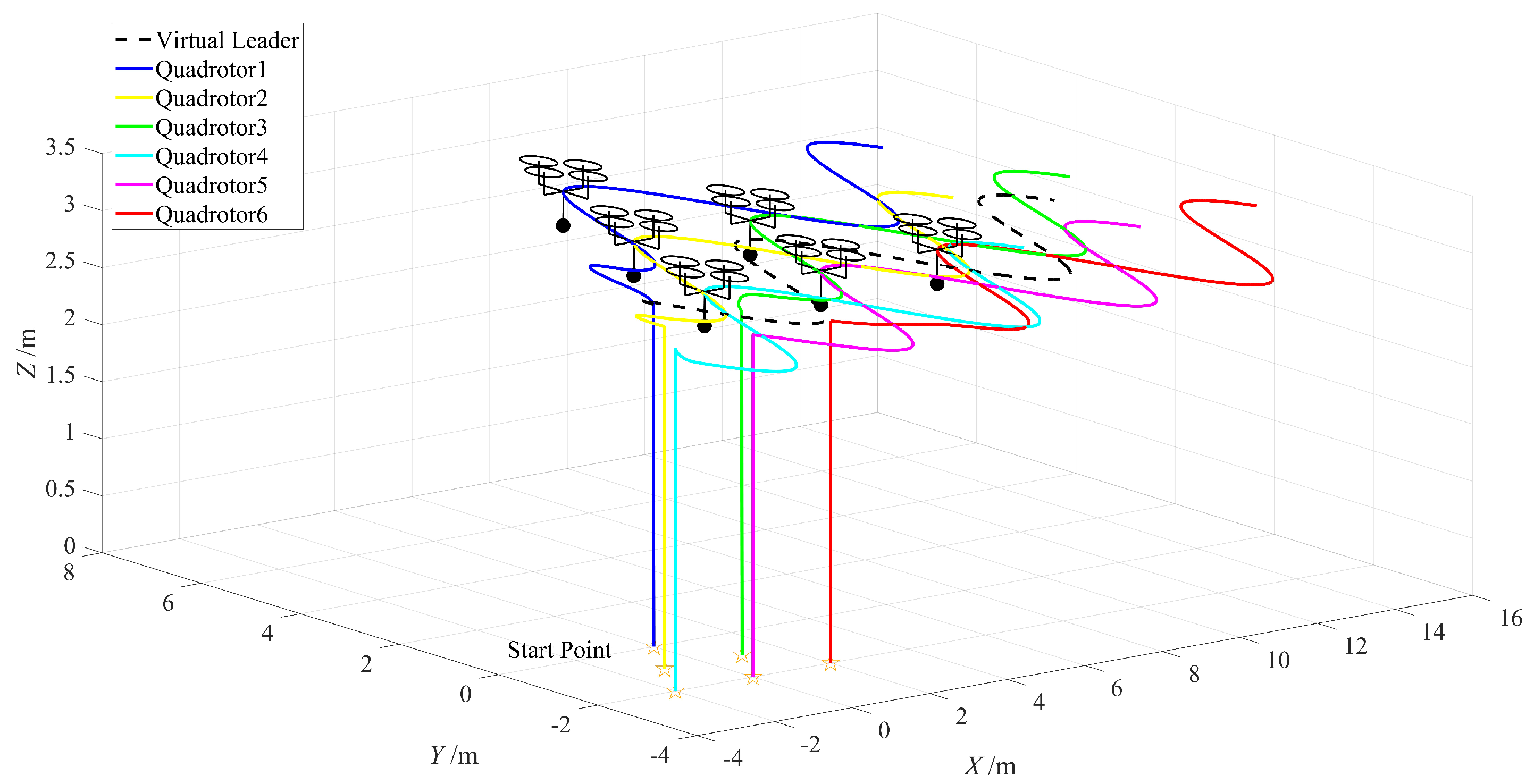
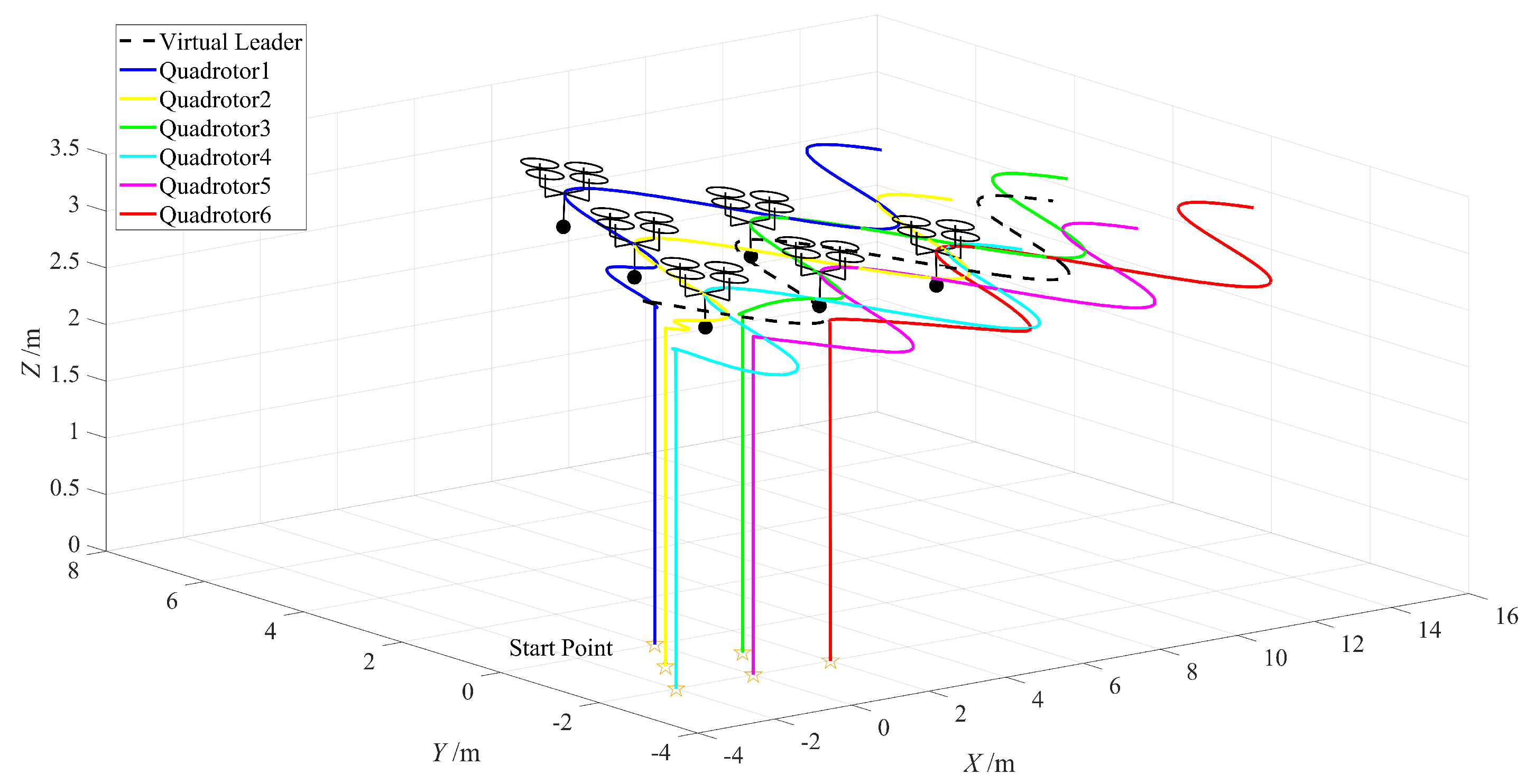
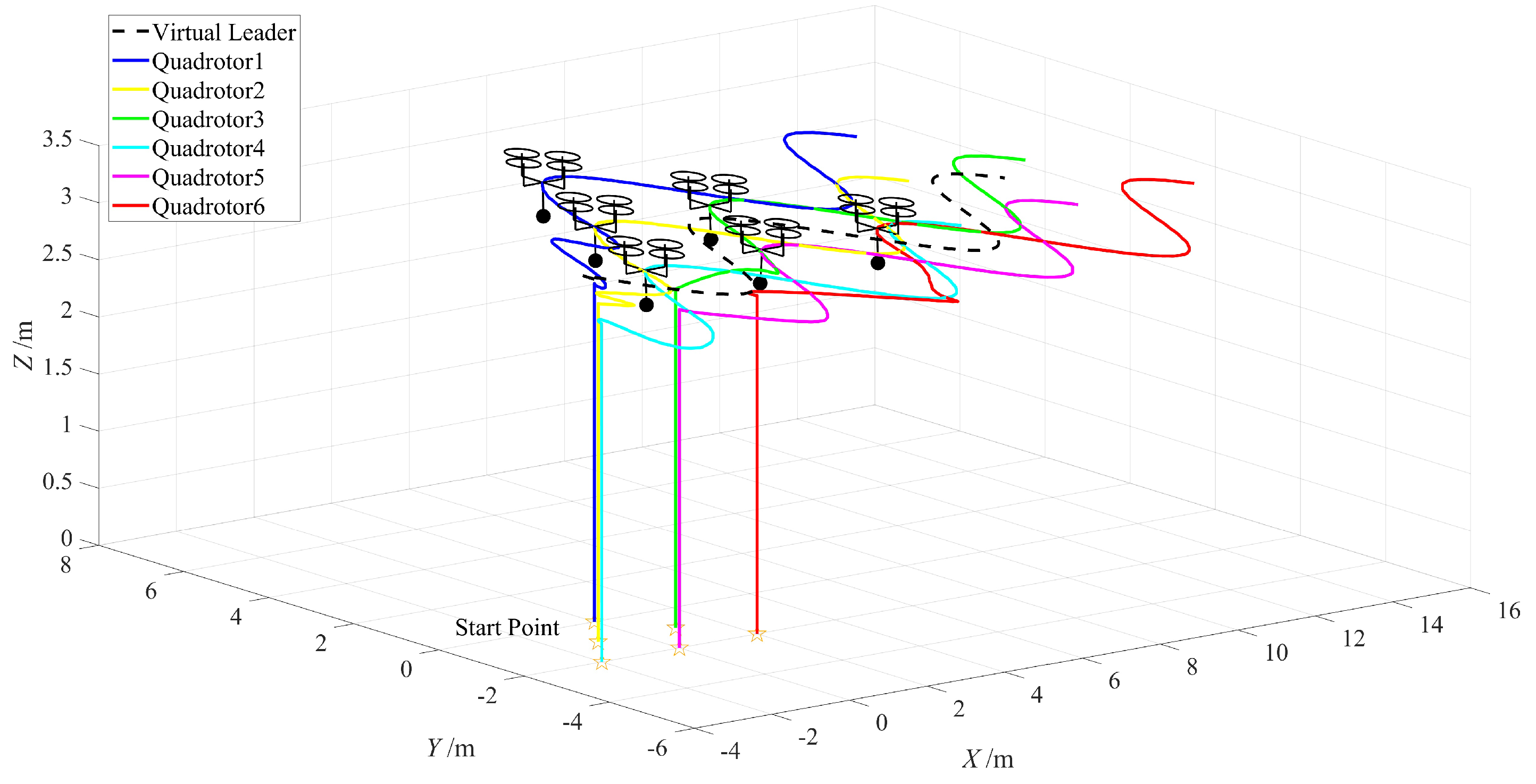
Figure 5,
Figure 6 and
Figure 7 illustrate the flight trajectories of six quadrotor suspension systems controlled by the designed method, backstepping control, and PID control, respectively. It is evident that all three methods enable the quadrotors to reach the desired altitude and successfully track their respective planned formation paths. Consequently, they achieve coordinated control of the multi-quadrotor suspension system. Nevertheless, variations in position control accuracy exist among these methods.
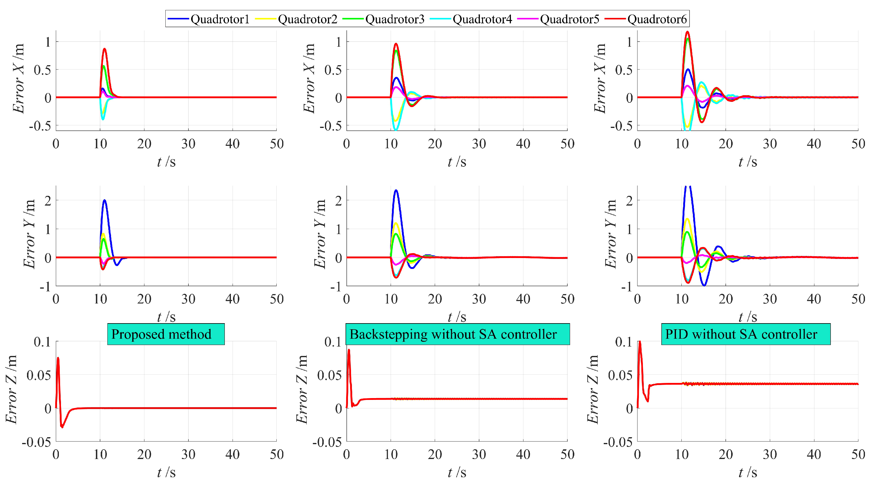
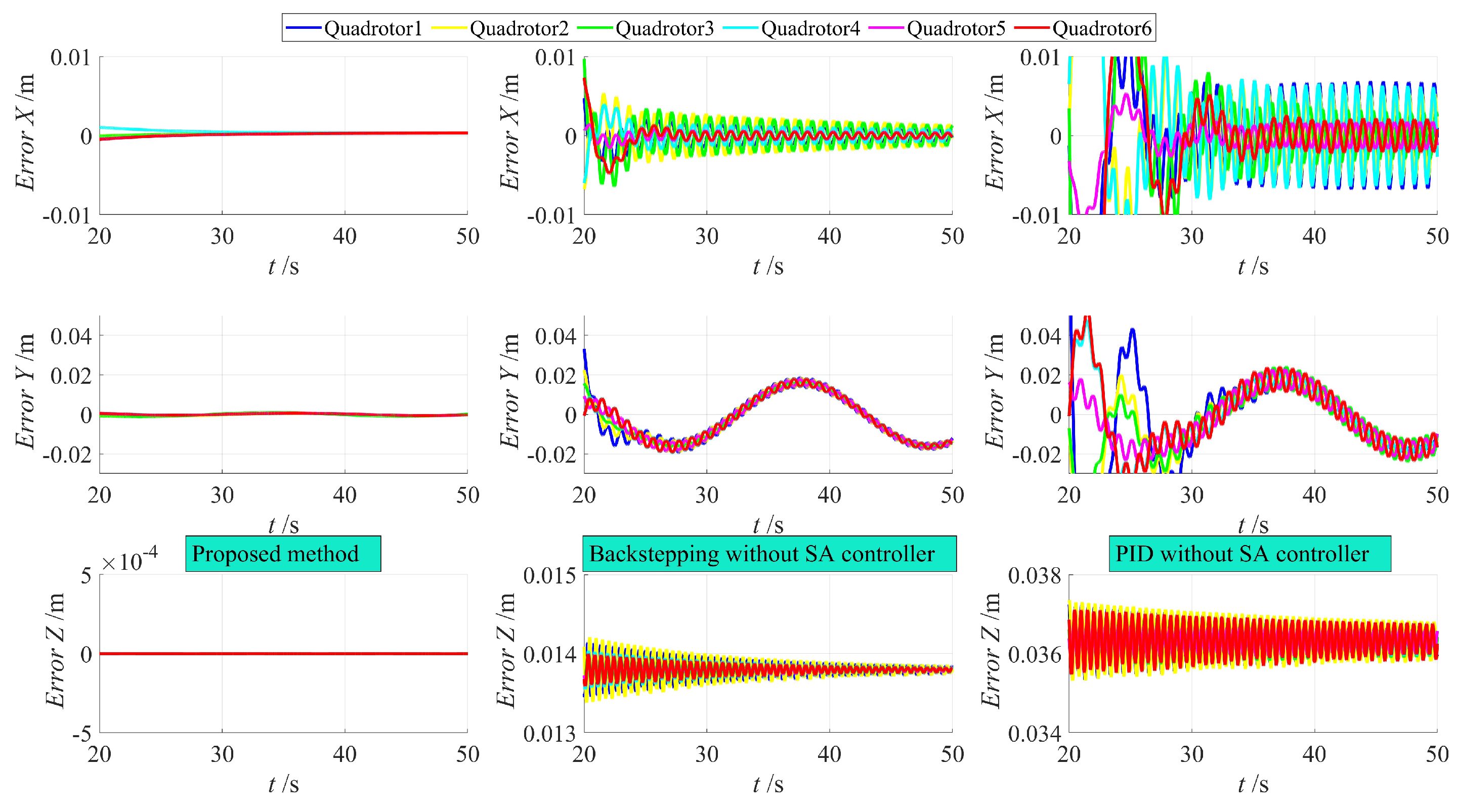
Figure 8 and
Figure 9 illustrate the position errors of the quadrotors using the three control methods. It is clear that, when compared to the control without the swing angle controller, the method proposed in this paper achieves stability within 5 s, while the backstepping method takes 10 s, and PID control requires 15 s. Furthermore, the approach outlined in this paper exhibits a smaller overshoot. Once stability is reached, the positions of the quadrotors are influenced by load swinging due to the absence of a swing angle controller. As a result, periodic errors persist even after stability is achieved, and this issue remains unresolved with the backstepping method, while PID control induces more significant oscillations. However, the design presented in this paper significantly mitigates the impact of load swinging, preventing the repetitive oscillation of quadrotor positions.
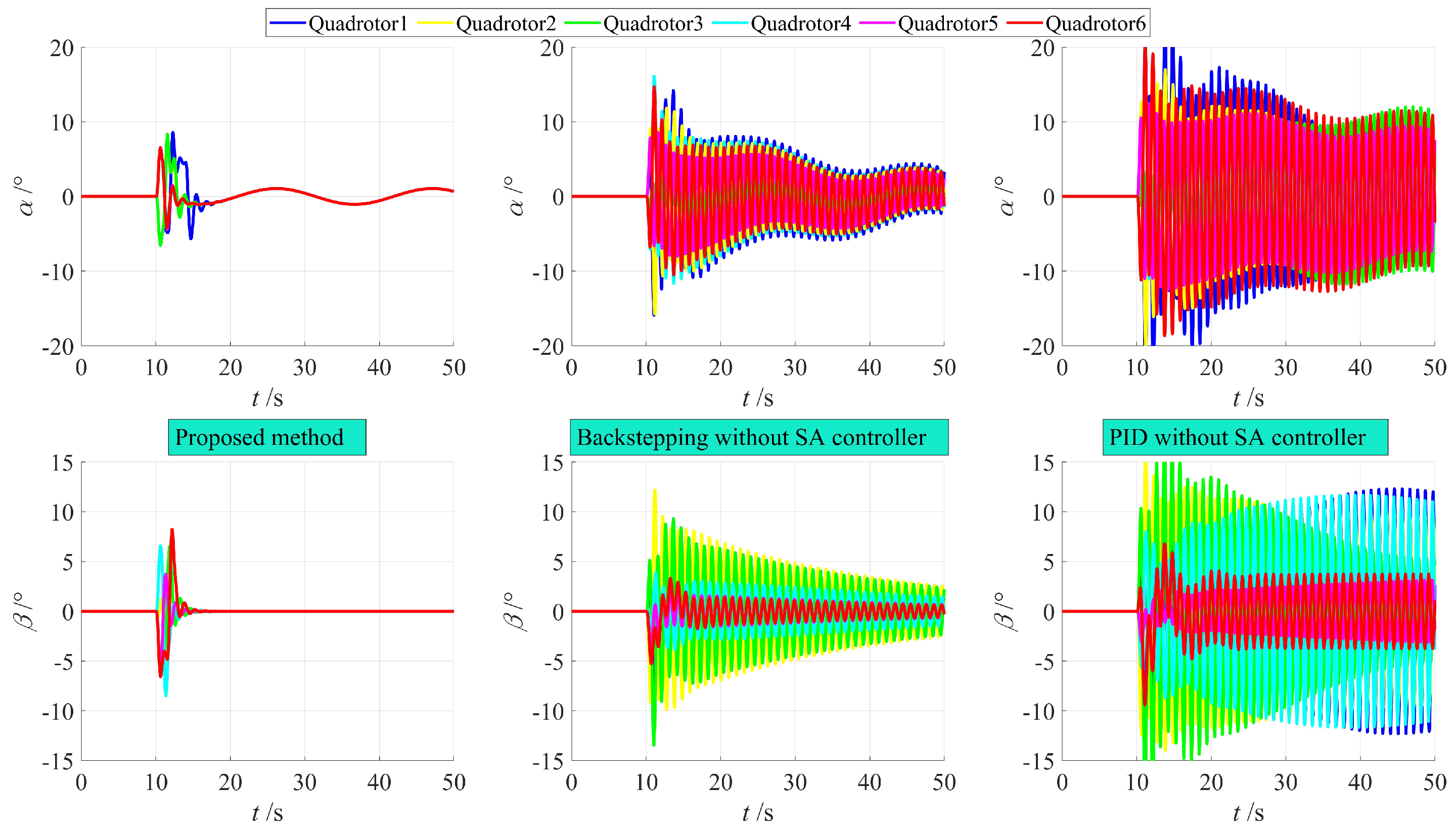
Figure 10 illustrates the swinging of the suspended load under the three control methods. It is evident that, with the swing angle controller in place, the suspended load experiences smaller swings when the quadrotor initiates horizontal movement and quickly achieves stability. Minimal swings occur as the quadrotor’s position undergoes periodic motion, with the absence of high-frequency oscillations. This design effectively mitigates the risks associated with excessive and frequent load swings.
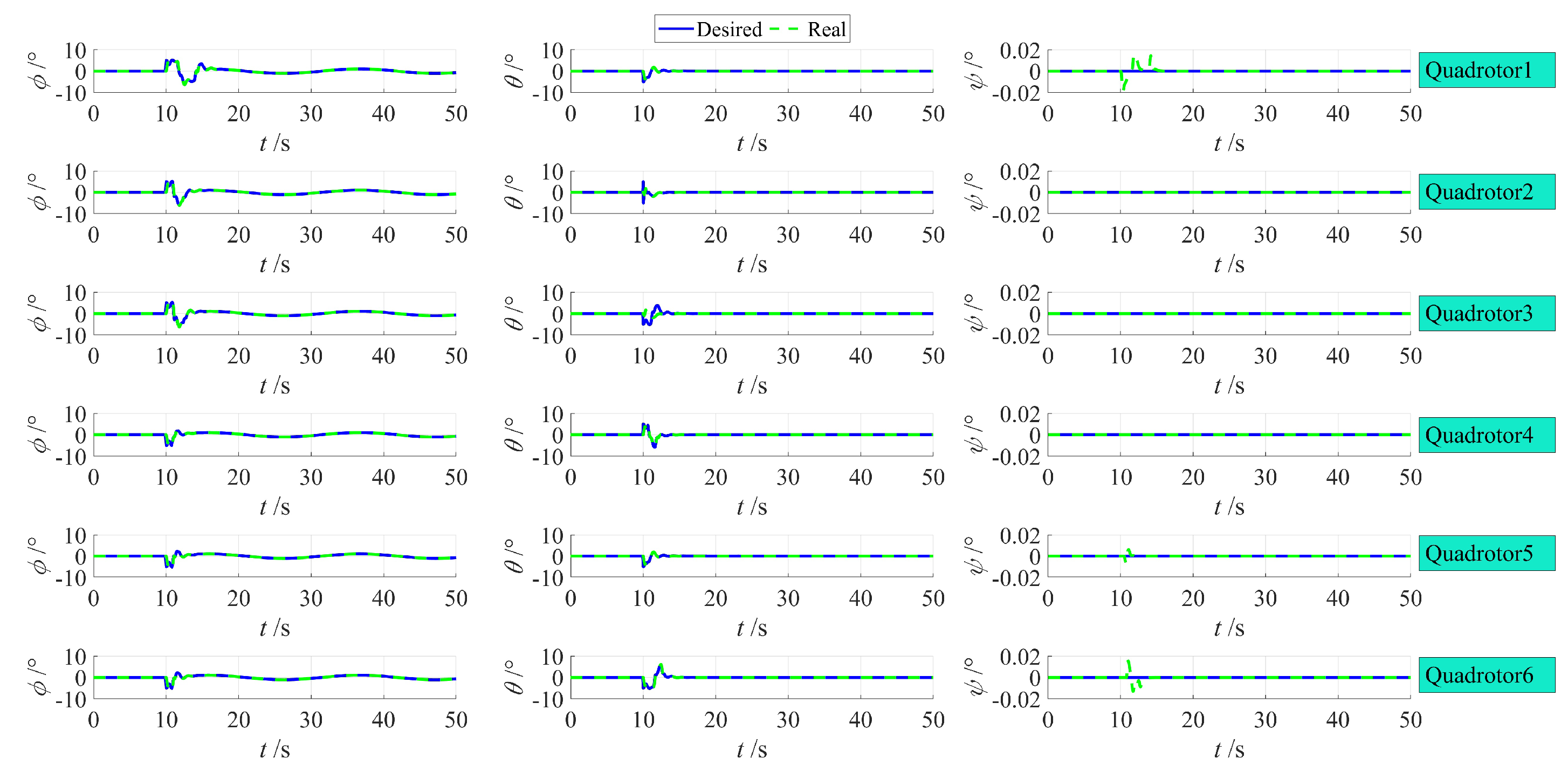
Figure 11 shows the control of the quadrotor’s attitude angles. It can be observed that the control method designed in this paper can accurately and quickly track the desired attitude angles.


