1. Introduction
Drag reduction by means of laminar flow technology has an unparalleled potential for improving the energy-efficiency of transport aircraft. Beck et al. [
1] state that for a state-of-the-art mid-range aircraft with fully laminar wings, tail and fuselage the total cruise drag can be reduced by up to 50%. Therefore, maximising the areas with laminar boundary layer is an important step towards significantly reducing emissions and achieving the goals of Flightpath 2050 [
2]. Natural laminar flow (NLF) by passive means and laminar flow control (LFC) by active suction are the two major approaches for delaying the laminar-turbulent transition and hybrid laminar flow control (HLFC) is a promising compromise, combining advantages of both. In most HLFC concepts, boundary layer suction is applied at the leading edge, resulting in laminar flow of up to 36% of the chord length in flight tests on commercial aircraft [
3]. So far, fully laminar wings have only been achieved on test aircraft using complex LFC systems without economic benefit [
4].
The Cluster of Excellence for Sustainable and Energy-Efficient Aviation (SE
2A) (
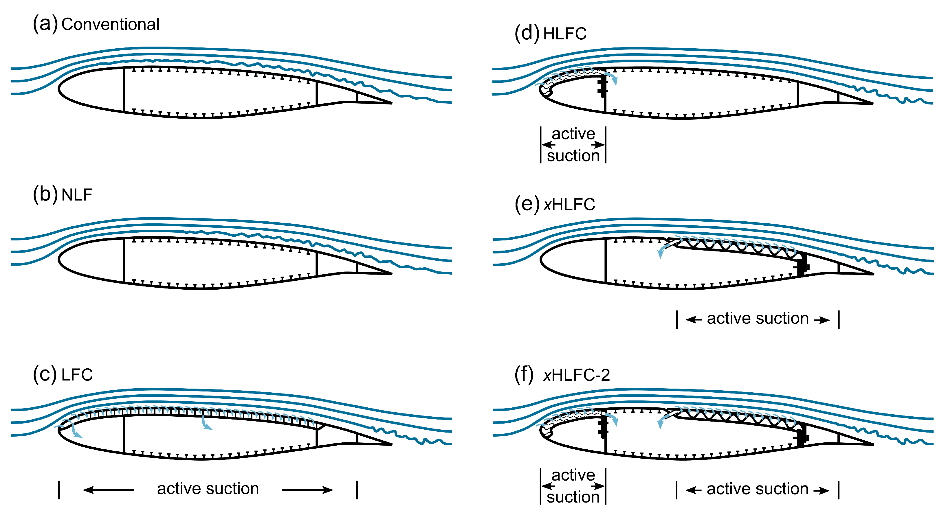
https://www.tu-braunschweig.de/se2a, accessed on 18 September 2023) is developing an extended HLFC suction panel (xHLFC), where in contrast to common HLFC concepts, the arrangement of LFC at the leading edge and NLF at the rear part of the wing is inversed [
5]. Applying suction on the rear part of the wing, the concept aims at maintaining laminar flow up to 80% of the chord length on the wing upper cover. A conceptual illustration of the xHLFC concept in comparison to NLF, LFC and HLFC is shown in
Figure 1 [
5].
Similar to existing HLFC concepts such as ALTTA [
6], ECHO [
7,
8] and TSSD [
9], the xHLFC-suction panel consists of three functional components as shown in
Figure 2 [
5]. The outer component is a thin, micro-perforated suction skin. It is supported by a core structure that stiffens the skins and does not obstruct mass flow for suction. The third component is the load-carrying wing structure made from carbon fibre reinforced polymer (CFRP), to which the suction panel is attached. The requirements of the suction panel components and suitable design solutions have been elaborated in detail in [
5]. The most important aspects are summarised below.
An essential requirement for the suction skin in order to maintain laminar flow is a high surface quality. In particular, this includes a low surface roughness and waviness as well as no steps and gaps. Critical roughness heights of 0.140 mm for a multi-bead band of distributed roughness were obtained from flight tests on a F-94A airplane at 22% chord for Mach 0.68 at an altitude of 26,000 ft [
4]. Earlier flight tests also showed that waviness amplitudes below 0.025 mm allow significant NLF regions on a Hurricane II and King Cobra aircraft at Reynolds numbers in the range of
. These requirements are usually fulfilled for modern state-of-the-art metal and CFRP wings. However, with resolutions and layer heights below 0.025 mm, state of the art additive manufacturing technology is a realistic option for manufacturing smooth surfaces for laminar flow applications.
For boundary layer suction, a suitable design and high quality of the perforation with respect to hole pattern, hole geometry and hole quality is important. Perforations are usually arranged in a hexagonal pattern to avoid eddies [
10], have a manufacturing induced cylindrical shape [
5] with diameters between 50
m and 250
m and cover porosities around 1% [
4]. Suction skins fulfilling these porosity and hole size requirements are laser-drilled or etched stainless steel or titanium sheets. However, preliminary investigations show such holes with an equivalent diameter below 250
m can be printed on stereolithography (SLA) machines, which allows the manufacturing of smooth, porous suction skins as an integrated part.
To ensure a smooth suction surface without waviness or wrinkling under wing load, the suction skin requires a dense support. Furthermore, hole blockage due to interfaces between suction skin and core needs to be minimised. A precise control of the pressure drop within the core structure, which influences the boundary layer suction rate, is essential to avoid under-suction as well as over-suction and hence guarantee a laminar boundary layer. Therefore, Traub et al. [
5] developed a suction panel concept for integral, additive manufacturing relying on a printed suction skin densely supported by triply periodic minimum surface (TPMS) core structures. In the proposed xHLFC concept, integral manufacturing of suction skin and core structures has been chosen in a morphological box approach to avoid joining of the two components and consequently hole blockage at the interface. The concept exploits the design freedom enabled by additive manufacturing in the form of 3D-printed suction skins of predefined porosity and TPMS as core elements, which allow for a passive suction rate control by modifying their friction surface to fluid volume ratio along the wing’s chord-wise position.
The mechanical characteristics of Gyroid and Schwarz Primitive TPMS structures have been extensively investigated by Traub et al. [
11]. Based on simulation and experimental results, they provide simplified models to estimate relative modulus and relative strength of the TPMS structures as a function of their relative density
, which is the ratio between the density of a TPMS unit cell and the density of the solid material with the same dimensions. The simulation models for Gyroid structures given in Equations (
1) and (
2) can be used in this paper to simulate the mechanical properties of the core for a given relative density. Thereby
is the compressive modulus of the cellular structure,
is the compressive modulus of the solid material. With the known material properties of the solid material, the equations allow to predict the characteristics of the cellular structure depending on the relative density. The analytical formulation also allows an optimisation of the core structure’s relative density, which is outside the scope of this paper.
Titanium, epoxy resins and polyamide (nylon) are considered suitable materials for suction skin and core structure as they can be manufactured using additive manufacturing (AM) and are standard in aerospace and automotive industry. While titanium has a high strength and resistance against abrasion, epoxy resins and nylon are lightweight and flexible materials, which minimise the attraction of strain-induced stresses. Titanium panels can be manufactured using selective laser melting (SLM), panels from epoxy resin can be manufactured using SLA and nylon panels can be manufactured using selective laser sintering (SLS). In contrast to the epoxy skins from SLA, which achieve a smooth surface, titanium and nylon skins are expected to require additional post processing. Due to the different mechanical properties of titanium, epoxy resins and nylon, the choice of material strongly influences the load path in the wing.
In a semi-monocoque wing structure, the wing skin is considered an inherently load-carrying component [
12]. As such, the upper wing skin, located below the suction panel, is also the main load-carrying component in the xHLFC-concept. Its task is to unload the suction panel and provide the stiffness needed to prevent the suction panel from experiencing excessive bending loads. Benefits from thin-ply laminates have been investigated in the scope of this research as an option to compensate for the additional mass associated with the suction panel integration [
13]. However, this is not taken into account in this paper.
The structural requirements of the suction panels vary strongly depending on their location on the wing. All components oriented in the direction of the flight path are exposed to the risk of bird strike [
14]. According to CS 25.631 from the European Union Aviation Safety Agency (EASA) the aircraft must be able to safely continue the flight and land after an impact with a 4 lb bird at cruise speed at sea level or at 0.85 cruise speed at 8000 ft, depending on which case is more critical. Therefore, the requirement to withstand high-velocity impact loads emerges for HLFC systems integrated at the leading edge. On the trailing edge, high impact loads, e.g., by bird strike, are not expected during flight.
Novel aircraft are increasingly manufactured from composite materials. The Airbus A350 e.g., uses a hybrid airframe consisting of composites and metal alloys. Considering bird strike resistance, the leading edge is commonly made from metal alloys such as aluminum [
15], whereas the lower and upper wing covers of the adapted A350 XWB are made entirely from lightweight CFRP [
16]. One benefit of using CFRP is the higher fatigue resistance, resulting in 60% fewer fatigue-related maintenance tasks [
15]. The risk of critical foreign object damage (FOD) during the manufacturing process e.g., due to dropped tools is increased when using composites, because small energies can cause delaminations within the composite material that can only be detected by non-destructive evaluation (NDE) [
17]. Therefore, also components on top of the wing must be able to withstand lower impact loads, which can as well result from hail-on-ground. In this study, the authors use a CFRP wing in combination with an on-top suction panel as a realistic scenario for a future energy-efficient aircraft. However, the choice of the wing material strongly influences the loading of the suction panel, with the panel experiencing higher loading at a lower wing stiffness.
Another aspect during flight operation are adhesive and erosive effects from atmospheric pollutants, such as aerosols, organic matter and rain. Adhesion of dust particles and insects can cause a significant increase in aircraft drag. Since smooth surfaces are crucial for HLFC systems, frequent washing routines may become even more important than for conventional aircraft and the additional efforts may counteract fuel savings from an economic point of view [
18]. The investigated xHLFC arrangement with the suction panel located at the rear part of the wing might be beneficial against contamination and clogging of the suction holes, since the major part of debris is typically found from the leading edge up to 15% of the chord length [
19]. The same applies to erosion, which mainly affects front-facing areas of the aircraft [
20]. Experiments of laser-drilled panels attached to the leading edge of the wing during real flight operation revealed immense differences in the extent of wear for titanium, aluminium and carbon fibre, with titanium showing best durability [
21].
In order to analyse the effects of the suction panel integration on structural wing design, a parametric finite-element (FE) wing generator has been developed based on the common parametric aircraft configuration schema (CPACS) [
22] (
https://www.cpacs.de/, accessed on 18 September 2023) and the associated geometry library TiGL [
23] (
https://dlr-sc.github.io/tigl/, accessed on 18 September 2023). Based on the FE model generator, the authors of this paper conduct a parameter study varying the suction panel thickness, material and relative density within physically meaningful boundaries. The results of the FE simulations show the total weight of the wing depending on the suction panel setup and the main load paths in the wing. The results allow an estimation of how the suction panel affects the wing structure and where weight can be saved.
To the author’s knowledge, similar investigations regarding the structural design of suction systems have not been conducted, yet. This is especially true for suction panels integrated at the rear part of the wing.
2. Model Generation and Sizing Methodology
The process of model generation and sizing methodology is shown schematically in
Figure 3. After parametrically defining the wing’s outer shape and inner structure in a CPACS XML file, the geometry is generated with TiGL and exported in the standardised STEP format. The geometry is imported into Abaqus 2019 where an FE model is built up automatically, based on a configuration file for the FE analysis. The automated FE model generation includes the assignment of properties, meshing and the application of loads and boundary conditions. While shell elements are used for surfaces, beam elements are added to model stiffeners such as stringer, spar caps, rib caps and vertical stiffeners. This is a commonly made idealisation for global wing models in order to balance the accuracy of the results and the modelling effort.
In addition to the basic wing structure, the model generator includes functionality for the integration of xHLFC suction panels, as depicted in
Figure 4. This involves modification of the wing structure where the suction panel is located. In the case of xHLFC suction panels, a sink is created in the upper wing skin based on the dimensions of the suction panel. The core structure is placed in the emptied space using solids and the suction skin is added on top of the core using shells. While isotropic material properties are assigned to the TPMS core structure based on the Equations (
1) and (
2), the effects due to the perforation of the suction skin are assumed to be negligible allowing to model it as unmodified isotropic material. This assumption is made, because the porosity of suction skins typically is in the range of 1% and only minor stress concentrations are expected due to the small size of the holes and their evenly distribution.
The wing generator contains methods for sizing wing structures according to an iterative fully stressed design (FSD) approach, used similarly e.g., in Sommerwerk et al. [
24]. In this approach, a failure index is calculated for each sizing criterion, shell, and stiffener. The failure index is equal to 0 when the component is unloaded and equal to 1 when the loading is equivalent to the allowed maximum loading. At the end of each iteration, the wall thickness of each shell and stiffener is adjusted based on their critical failure index. The primary structure of the wings investigated in this study, is made from CFRP and Puck’s failure criterion is used to assess fibre and inter-fibre failure [
25]. Buckling is checked by linear stability analysis, where local buckling of skin panels has to be prevented up to limit load and global buckling has to be prevented up to ultimate load. A similar procedure has been used by Hürlimann et al. [
26]. Von-Mises stresses are used to evaluate strength failure of the suction panel components. Due to its low thickness, a semi-empiric wrinkling criterion according to Plantema [
27] is calculated additionally for the suction skin. As a simplification, a continuous support of the suction skin by the core structure is assumed:
with
Table 1 and
Table 2 give the material properties used for the unidirectional layers in the laminates of the primary wing structure and the isotropic properties used to model suction panel components and beam stiffener. A quasi-isotropic layup is chosen and a knockdown factor of 0.5 is used for all laminates to account for additional mass needed in a more detailed design.
The relative density of the TPMS cores and the thickness of the suction skin remain constant within each sizing, even if a sizing criterion of the suction panel is violated. Instead, the supporting primary structure underneath the overloaded suction panel is reinforced to unload the panel. Several parameters such as damping and smoothing parameters and maximum step sizes for the wall thickness modification within a single iteration, influence the convergence behaviour of the FSD. For the simulations conducted in the scope of this research, the following settings turned out to yield good convergence:
In FSD, convergence is reached if the difference in total mass between consecutive iterations is below a defined limit. In this study a sizing is considered to have converged, if this difference is less than 1.0% in two consecutive iterations. Two additional iterations are performed in which no material is removed, but material can be added, if there are still failure indices above 1.0. The FSD does not necessarily converge in the global optimum solution. It is, however, efficient in finding local optima and the solution is well comprehensible.
3. Simulations
The influence of the suction panel integration on the wing mass is studied in this paper using the example of a fully electric short-range aircraft developed by Karpuk [
28] within the frame of SE
2A. The aircraft’s top level requirements have been derived from an ATR-72: the aircraft is supposed to carry 70 passengers over 900 km. The battery-powered propellers are mounted at the rear fuselage, avoiding disturbances over the wing and alleviating difficulties in maintaining laminar flow. Active suction is applied between 50–80% of the chord over the whole span, as illustrated in
Figure 4. The conceptual design makes technology assumptions for the year 2050. Due to the expected development of improved load alleviation technologies, a critical load factor of 2.0 g is taken compared to 2.5 g in today’s certification specifications.
The reference suction panel is defined with a core thickness
of 24 mm, a relative density of the core
of 10%, a suction skin thickness
of 0.5 mm and each of the selected materials, namely Ti6Al4V, PU1000 and Nylon11CF. Based on these references,
(16 mm, 20 mm),
(5%, 15%) and
(0.25 mm, 1.0 mm) are varied independently, leading to the test matrix given in
Table 3.
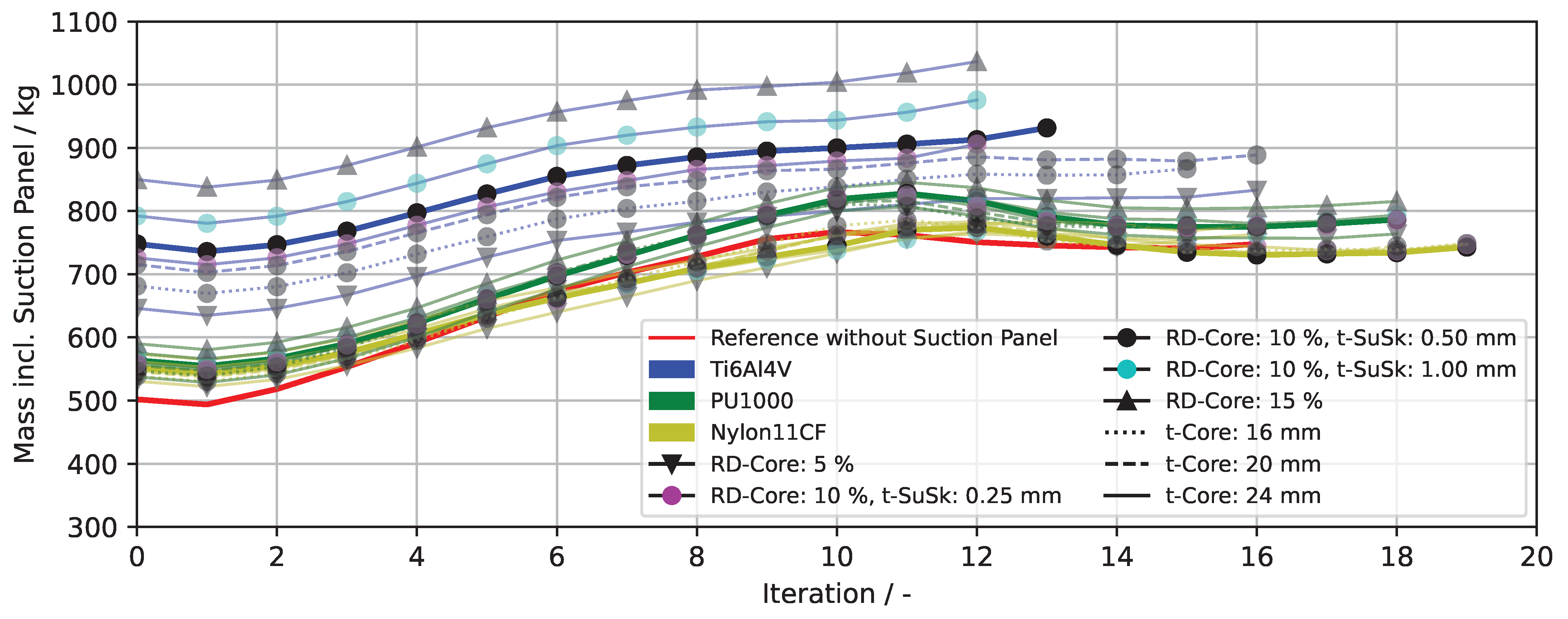
Figure 5 shows the convergence behaviour within the FSD. With the chosen parameters, all sizings converge in 11–18 iterations. Difficulties in obtaining a converged solution in a few iterations can be caused by the stability criterion, as it does not return a failure index for skin panels that do not buckle within the calculated number of eigenvalues and eigenmodes, respectively. Theoretically, the thickness of a single panel sized by buckling can alternate between a state where it buckles and another state where it is not captured from the buckling criterion, preventing convergence. Increasing the number of eigenvalues to be computed can mitigate this effect at the cost of increased computational effort. The subsequent subsections examine the effects of the conducted parameter variations, addressing resulting masses, load transfer within the wing structure and implications for specific sizing criteria.
3.1. Suction Panel Material
As the suction panel configuration within a single sizing is fixed, the suction panel mass remains constant in each sizing. For the reference suction panels this adds a fixed mass of 248.3 kg (Ti6Al4V), 64.0 kg (PU1000) and 52.4 kg (Nylon11CF), respectively per wing. In the case of the Ti6Al4V suction panel, this is equivalent to approximately 26.7% of the xHLFC-wingbox. In the most unfavorable design in terms of additional mass (Sizing ID 5), the fraction even increases to 33.8%.
Nevertheless, the suction panels not only add mass, but also stiffness to the wing. Depending on the material properties, the load transfer over the wing differs strongly.
Figure 6 shows the section forces, and therefore the load transfer, over four cross-sections for the Ti6Al4V and Nylon11CF reference suction panels in a 2 g load case. The load transfer in the PU1000 reference suction panel is not depicted, as it is similar to the Nylon11CF configuration. The section forces represent the transferred load per unit width. Therefore differences in the wall thickness of adjacent skin panels in the composite structure lead to steps in the load transfer. Apart from these steps, the section forces resulting from wing bending are roughly proportional to the distance from the neutral plane.
However, there is a shift in section forces towards the area in front of the suction panel. On the one hand this results from the fact that the area equipped with suction panels is lowered, reducing the distance to the neutral plane of the upper wing cover here and that the aerodynamic loads resulting from the pressure distribution are largest at the front. On the other hand this effect is amplified by the nature of the FSD: In the Ti6Al4V-sizing (Sizing ID 1,
Table 3) buckling does not occur in the areas equipped with suction panels as they can be seen as classical sandwich structures and therefore their buckling stiffness is relatively high. However, the semi-monocoque structures in front of the suction panels are still prone to buckling. Increasing the wall thickness to prevent buckling in the front part of the wing unloads the wing structure in the rear part, which in the next iteration can lead to a reduction in wall thickness there and ultimately to increased loads in the front again. The comparison of the configurations illustrates the fact that buckling of the suction panel regions does occur in the Nylon11CF sizing (Sizing ID 15,
Table 3). This is also true for the PU1000 sizing (Sizing ID 8,
Table 3).
Figure 6b also shows that buckling mainly occurs in the inner wing, as the step in the section forces in the upper skin in the transition area between semi-monocoque and suction panel is not as clear for relative spanwise coordinates of 15 and 30% as it is for 60%. It has to be mentioned that the step in the Ti6Al4V-sizing appears larger than it is, because the suction panel components contribute significantly to the load transfer, here. This difference is discussed in the following paragraph.
The stiffness of PU1000 and Nylon11CF is very low compared to the stiffness of the composite material applied to the backbone structure. Therefore, the load transfer via the suction panel is negligible with these materials. In contrast, the stiffness of Ti6Al4V is even higher than the stiffness of the quasi-isotropic composite layup. The loads are distributed to the single components similarly to classical laminate theory (CLT). Therefore, the Ti6Al4V suction panel transfers significant loads. In Sizing 1 the loads transferred by both suction skin and core structure have the same order of magnitude as the loads carried by the underlying laminate. It is worth noting that the suction skin transfers approximately two thirds of the loads that the core structure carries, although it has only about 20% of the mass. This results from the relatively low specific mechanical properties of TPMS structures with low relative density. This ratio becomes even more extreme for suction cores with lower relative density (e.g., Sizing ID 4,
Table 3). The effect is more detrimental for Ti6Al4V than for PU1000 and Nylon11CF as their densities are significantly lower. For the short-range aircraft with maximum load factors of 2.0 g investigated in this study, the advantage of the high mechanical properties of Ti6Al4V do not fully come into play, as the laminates in large areas equipped with Ti6Al4V suction panels are already sized by minimum wall thickness limitations. Adding a suction panel with high mechanical properties will therefore rather lead to a decreased material exploitation than to weight savings due to a reduction in laminate thickness.
3.2. Relative Density of TPMS Core Structures
Increasing the relative density of the core structure proportionally increases its mass, which due to the ratio between
dominates the actual mass of the suction panel. Therefore, minimising the relative density is crucial for obtaining a lightweight solution. On the other hand, especially for low relative densities, the specific stiffness of TPMS structures is significantly lower than that of homogeneous materials of the same density (see Equation (
1)). A reasonable compromise between these competing objectives needs to be found.
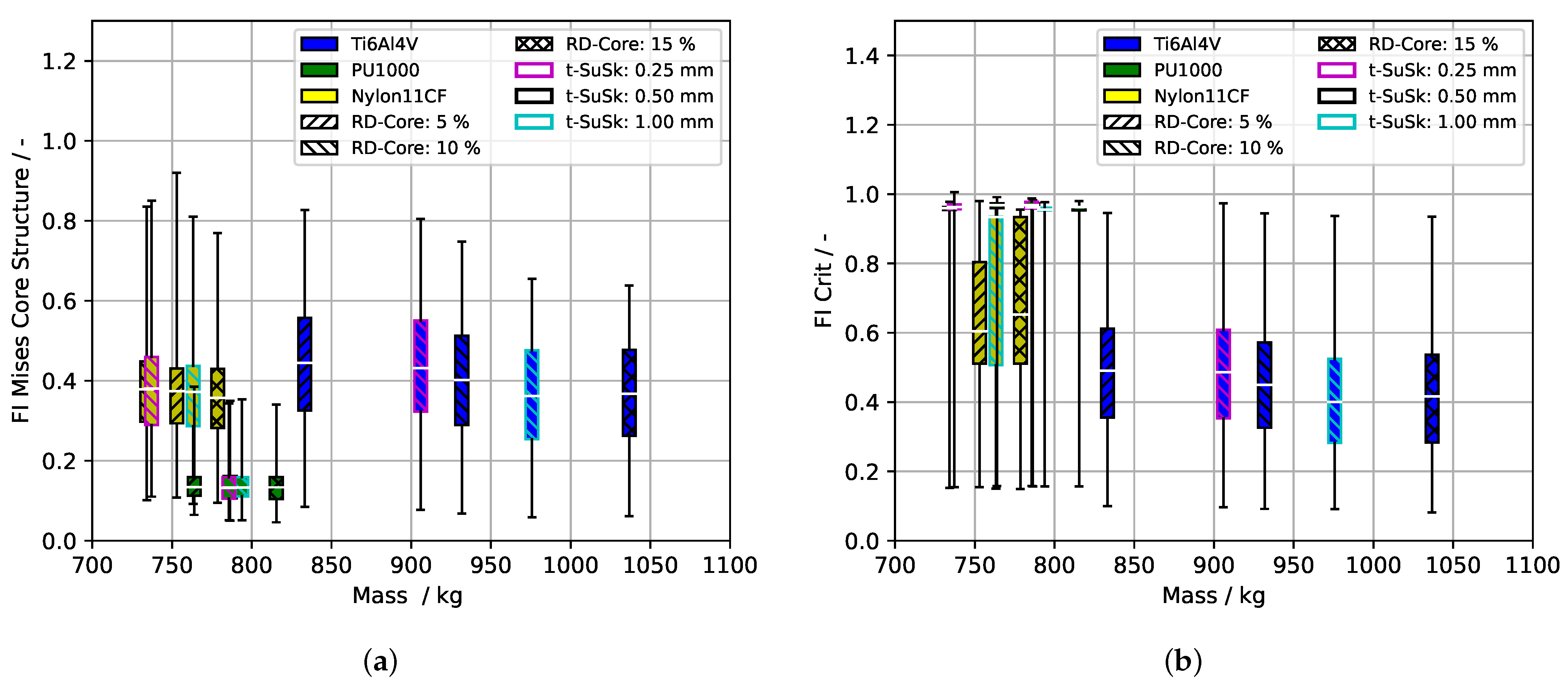
Figure 7a shows the failure indices of the Von-Mises-criterion for the TPMS cores. In this and all following boxplots the whiskers indicate 5% percentiles. The clear distinction between the different materials confirms the assumption that the failure indices strongly depend on the ratio between strength and stiffness of the TPMS structures, as similar assumptions compared to CLT can be drawn for the xHLFC design. More precisely, the stiffness specific strength is inversely proportional to the failure index. The Equations (
1) and (
2) give qualitatively similar dependencies between relative strength and relative stiffness with respect to relative density. Therefore, the basic material properties dominate the failure indices.
Table 2 shows the ratios between
for the three investigated materials. The correlation is particularly evident for Nylon11CF and PU1000. The ratio between the failure indices of both materials (Nylon11CF: ∼0.4, PU1000: ∼0.14) is close to the reciprocal of the ratio between their stiffness specific strength (Nylon11CF: 13.02, PU1000: 38.04). For Ti6Al4V this connection is less obvious. However, this is related to the fact that larger parts of the area equipped with suction panels are sized by minimum wall thickness, resulting in significantly lower critical failure indices for the Ti6Al4V suction panels as explained in
Section 3.1 (see
Figure 7b).
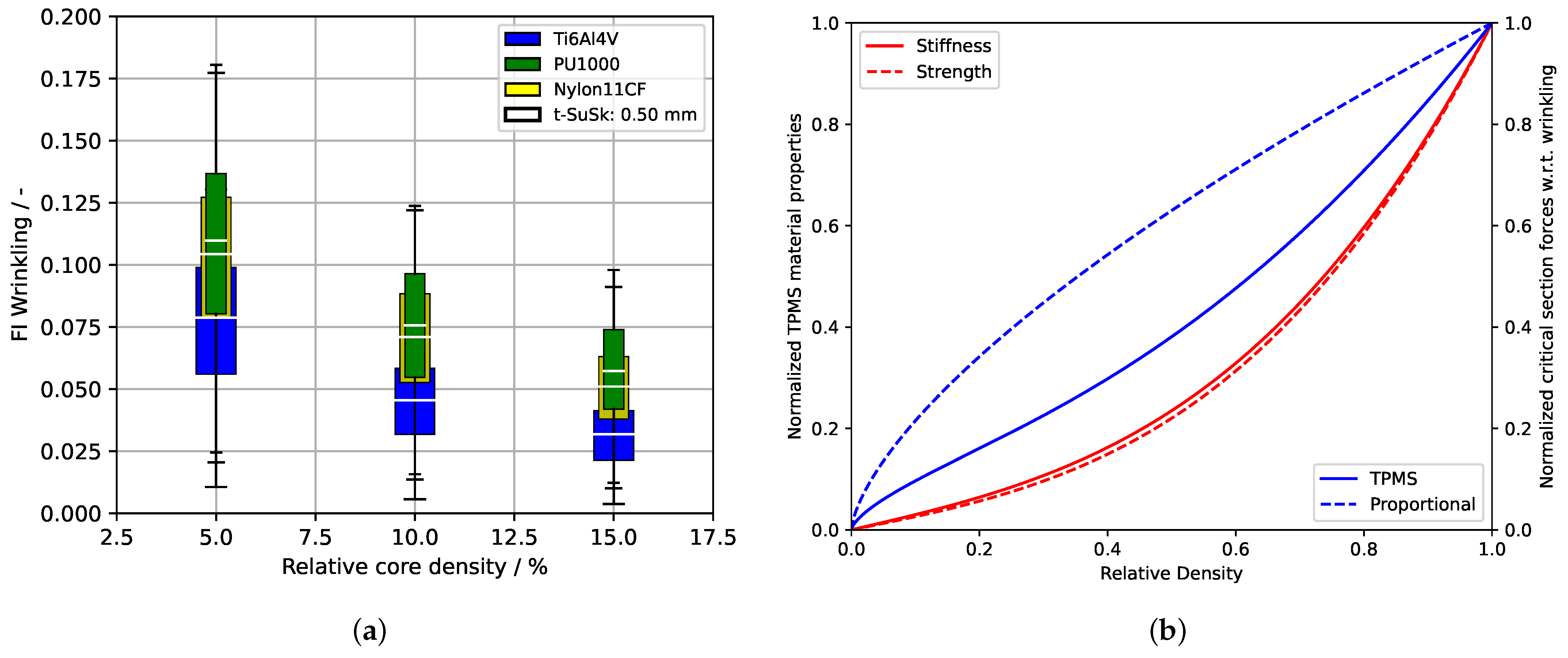
Figure 8a shows the strong impact of the relative density of the support structure on the critical section force with respect to wrinkling. For all materials a progressive increase in the wrinkling failure index towards lower relative densities can be assumed. This trend can be explained by the non-linear change in stiffness of TPMS core structures as a function of their relative density (see Equation (
1)), which decreases asymptotically, when decreasing the relative density and which is included twice in the calculation of the critical section forces (see
and
in Equation (
4)).
Figure 8b illustrates this relationship and also shows the influence on the wrinkling criterion compared to a solid material of proportionally scaled stiffness.
As mentioned above, the support of the suction skin is assumed to be continuous in the calculation of critical section forces regarding wrinkling, while in fact it is not. For a wall thickness in the range of 0.25 mm and 1.0 mm, wrinkling and intra-cellular buckling do not appear to be critical, as the failure indices of the wrinkling criterion are well below 0.2. However, the criteria will become critical when expanding the parameter range towards lower relative core densities. Intra-cellular buckling should therefore be considered in the future, too.
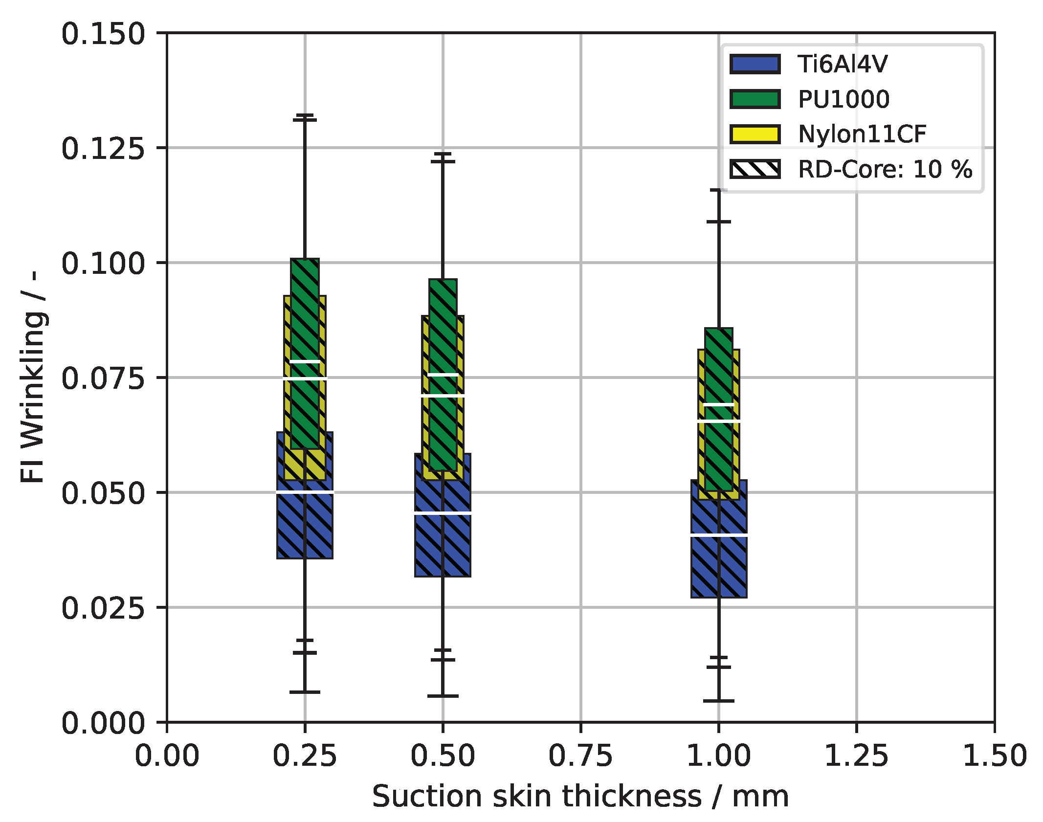
3.3. Suction Skin Thickness
The thickness of the suction skin only has a small effect on the additional mass, as it is relatively thin and, when made from Ti6Al4V is able to significantly contribute to the load transfer. In contrast to the buckling stiffness of stiffened panels, which follows a cubic relationship with the shell thickness, the wrinkling stiffness only increases proportionally with the shell thickness (see Equation (
4)). The reason for this behaviour is the continuous support provided by the core structure. However, not even the proportional relationship can be found in the resulting failure indices for wrinkling shown in
Figure 9, because with decreasing suction skin thickness also the loads transferred by the suction skin decline. Instead, the failure indices only increase linearly with a small slope towards a lower suction skin thickness.
3.4. TPMS Core Thickness
Modifying the TPMS core thickness proportionally affects the mass of the suction panel. The influence on the load transfer within the wing is almost negligible in the parameter range investigated in this study, due to the reduced stiffness of TPMS structures with low relative densities. Changing the core thickness does not affect the wrinkling criterion as long as the core thickness is large in comparison with the suction skin thickness. For the Ti6Al4V suction panels buckling did not occur with all conducted core thickness variations. It is therefore rather advantageous to use a lower core thickness with a higher relative density than vice versa and avoid extreme reductions in TPMS stiffness, if the aerodynamic requirements allow.
5. Conclusions
In this study, parameter variations of possible xHLFC suction panel configurations were performed and their effect on wing mass and load transfer was investigated. Of the three materials considered in this study, suction panels made from Ti6Al4V offer the most robust design. On the downside, they are associated with significant increases in wing mass. Suction panels made from Nylon11CF or PU1000 in contrast do not significantly affect the wing mass. On the other hand, questions regarding their feasibility under operational conditions remain open. This concerns both erosive effects and minor impacts. The results obtained in this study highlight the impact of the material choice on the load path within the wing structure. Ti6Al4V suction panels offer high mechanical properties that significantly contribute to load transfer and buckling stiffness. In contrast, compliant materials such as Nylon11CF or PU1000 are inherently decoupled from load transfer. Unlike the thickness of the suction skin, the relative density of the core structure strongly affects the wrinkling stiffness. However, wrinkling failure did not appear to be critical for the suction panel configurations analysed in this study. Compliant suction panels made from Nylon11CF seem to be the most promising option for achieving a lightweight solution, if they are able to meet operational requirements.
In order to enhance the technological readiness of the xHLFC concept, it is necessary to refine the selection of failure criteria in the wing sizing process. As mentioned above, intra-cellular buckling of the suction skin becomes a relevant sizing criterion when extending the parameter range of the core structure’s relative density towards lower limits, thus increasing the cell size and the buckling length. It is also important to thoroughly investigate the fatigue behaviour of TPMS core structures and micro-perforated suction skins, as this is a prerequisite for a robust suction panel design.
Considering aircraft operations requires considering operational aspects for the suction panel. One such aspect is a minimum impact resistance, e.g., using the hail-on-ground load case. Flying through hail is generally avoided due to the potential risks involved. On ground, various protective measures can be implemented to safeguard susceptible components, such as equipping the xHLFC aircraft with hail-resistant covers in the rare event of a hailstorm. However, the example of hail-on-ground provides a starting point for a discussion on minimum requirements regarding impact. With respect to operations and maintenance, advantages from placing the suction panel at the rear wing instead of the leading edge, need to be quantified. This concerns erosive effects as well as possible clogging of the micro-perforation. Significant concentrations of atmospheric pollutants are typically located in the lower atmosphere and are relevant during take-off and initial climb [
29]. However, the composition and magnitude varies strongly both geographically and with local and temporal effects. As HLFC increases the complexity of the overall system and might be affected by atmospheric aspects, aircraft operation is conceivable to have a noteworthy impact on performance, wear and eventually maintenance, repair & overhaul (MRO). Tracking of flight activities and coupling with atmospheric data might gain relevance in decision-making for condition-based maintenance, as it is already exerted for aircraft engines. Flight data and models for HLFC liability to operation are so far missing, but could become relevant in near future.
In the present study, the suction panel configuration was fixed within each sizing. Integrating suction panel parameters into the sizing problem promises further mass reductions. This holds true especially for the relative density of the core, which, from a manufacturing point of view, can easily be modified using 3D-printing. Lowering the load-carrying structure in order to create a sink for the suction panel reduces the planar moment of inertia in the rear part of the wing. In the simulations, this resulted in a forward shift of section forces and wall thickness within the primary structure. The effect of this redistribution on mode shapes and aeroelastic behaviour of the wing needs to be studied in the future. However, it is assumed that the shift has a positive effect on resistance against torsional divergence, as it is associated with a forward shift of the shear centre.


 ,
, 


