Abstract
Recently, an Unmanned Aerial Vehicle (UAV)-based Wireless Sensor Network (WSN) for data collection was proposed. Multiple UAVs are more effective than a single UAV in wide WSNs. However, in this scenario, many factors must be considered, such as collision avoidance, the appropriate flight path, and the task time. Therefore, it is important to effectively divide the mission areas of the UAVs. In this paper, we propose an improved k-means clustering algorithm that effectively distributes sensors with various densities and fairly assigns mission areas to UAVs with comparable performance. The proposed algorithm distributes mission areas more effectively than conventional methods using cluster head selection and improved k-means clustering. In addition, a postprocessing procedure for reducing the path length during UAV path planning for each mission area is important. Thus, a waypoint refinement algorithm that considers the sensing ranges of the sensor node and the UAV is proposed to effectively improve the flight path of the UAV. The task completion time is determined by evaluating how the UAV collects data through communication with the cluster head node. The simulation results show that the mission area distribution by the improved k-means clustering algorithm and postprocessing by the waypoint refinement algorithm improve the performance and the UAV flight path during data collection.
1. Introduction
Recent technological advancements and the widespread use of Unmanned Aerial Vehicles (UAVs) have led to the emergence of UAV-enabled wireless communication for data collection and distribution. The use of UAVs in sensor networks has resulted in the establishment of UAV-based Wireless Sensor Networks (WSNs) [1]. The goal of the WSN is to maximize the longevity of the network while delivering raw data to the sink (base station). Therefore, energy efficiency is one of the most important performance evaluation factors for WSNs. Energy efficiency is a measure of how a sensor consumes energy over time and continues to operate until the end of its life. Because sensor nodes are battery-powered, energy consumption is the most important factor in determining the lifetime of a wireless sensor network. Most sensor nodes are small in size and have limited battery capacity, and battery replacement or charging is often impossible or difficult due to the nature of the environment. Therefore, it is critical to operate the sensor nodes while considering the energy efficiency. WSNs can be applied in a variety of fields, including medical applications, military surveillance, industrial automation, environmental applications, agriculture, emergency situations, and homeland security [2]. A WSN includes hundreds of sensing, computing, and communication nodes distributed over a specified network area, with sensor nodes randomly placed in the defined network area. The sensor node detects the physical environment and transmits the detected data to a Base Station (BS); however, in general, the sensor node has limited energy resources. The sensor nodes transfer data through single-hop or multi-hop communication modes, and it is impossible to directly transmit data obtained in wide-area network scenarios to base stations due to the limited energy resources of the sensor node. Therefore, in WSNs spread across a large network area, the limitations of individual sensor nodes may interfere with the overall performance of the system. In addition, the use of wireless sensor nodes increases the power consumption due to the continuous data exchange, resulting in limitations in transmitting data to the base station. To address these limitations, UAVs have been utilized for data collection in WSNs to manage the energy consumption of the network, expand the monitored areas, and improve the overall performance. UAVs are used because they can be placed quickly and moved in flexible trajectories in three-dimensional space, increasing signal transmission reliability by enabling short-range communication with ground nodes through strong air-to-ground Line-of-Sight (LoS) links. In addition, UAVs are effective for collecting data from sensor nodes in dense environments as well as in areas that are difficult to reach with ground vehicles [3].
In a UAV–WSN environment, UAVs serve as data agents, collecting and transmitting data from sensor nodes to a base station. The fundamental mission of a UAV is to depart from the base station, visit all sensor nodes to collect data, and return to the BS [4]. In smaller network areas, a single UAV can efficiently cover all sensor nodes. However, in larger networks, where the area is extensive, a single UAV with limited battery capacity cannot effectively cover numerous sensor nodes. In such cases, options include frequent return trips to the base station for recharging or the collaboration of multiple UAVs for mission execution. Multiple UAVs operating as a network have been utilized in various domains, including public safety, commercial ventures, and military operations such as search and rescue, disaster relief, precision agriculture, environmental sensing, and surveillance.
While previous studies have addressed the coverage path planning with multiple UAVs for wide regions [5,6,7], the focus primarily remained on whether the entire area could be covered by the UAVs’ flight paths. Detailed tasks, such as area navigation and information collection, were often overlooked. Moreover, when multiple UAVs collaborate, complex considerations like collision avoidance, flight path, and mission time for each UAV must be factored in. Among these considerations, the optimal flight path in UAV path planning has been studied [8]. Minimizing the path length, reducing the mission time, decreasing fuel consumption, designing a path planning algorithm according to each objective function, and maximizing the safety and viability of the UAVs based on obstacle collision avoidance and terrain collision avoidance have all been considered. However, most studies have focused on path planning algorithms rather than how to allocate the mission area of multiple UAVs. Additionally, detailed waypoint planning for UAVs has also received limited attention. In [9], improvements in the UAV’s flight path were made by establishing waypoints within its communication range. However, the overlapping communication range and mission time were not adequately addressed.
This study proposes an improved k-means clustering method designed for effectively partitioning the mission areas of multiple rotary-wing UAVs within sensor distribution environments exhibiting varying densities. Then, the Cluster Head (CH) node is selected, and the task area is distributed. The Waypoint Refinement Iteration (WRI) algorithm, accounting for the UAV’s sensing range, is presented to enhance flight paths and mission completion times. It resets the waypoint based on the sensing range of the sensor node after path planning in multi-UAV environments. Numerical simulations are presented to verify the performance of the proposed framework.
2. Related Work
Data aggregation techniques for WSNs have been studied to maximize the lifespan of the network with the energy of the sensor nodes [10]. The number of sensors that transmit data to the base station can be minimized by utilizing the data correlations between different sensor nodes. Compression sensing techniques have also been studied to reduce the amount of data to be transmitted [11]. However, in [11], the path planning of the UAV was not considered. Chawra and Gupta [12] used salp-swarm optimization to select CH nodes for data collection in cluster-based WSNs and used Differential Evolution (DE)-based metaheuristics to plan the flight path of UAVs. In this work, the cluster-based sensor nodes were simply divided into quarters around the base station, and the mission area of each UAV was distributed; that is, only an environment with a uniform density across all sensor nodes was evaluated, with the BS at the center. However, this method is not applicable in environments with various sensor distributions with different densities. In such environments, it results in unfair distribution of mission areas to UAVs. Moreover, this method cannot be applied if the number of UAVs increases. In [13], a task was assigned to each UAV by determining the peak density with a novel density-based clustering algorithm that considered the density of the sensor nodes. However, with this method, there may be an unequal distribution among the mission areas because the density is the only factor considered.
For path planning in UAV-WSN environments, the UAV must visit sensor nodes to collect data. Furthermore, the UAV must remain within the sensor’s communication range while collecting the data. The entire path must be configured to ensure that the UAV returns to the base station after collecting data from each sensor. For efficient data collection in WSNs with randomly placed sensors, it is preferable to utilize a rotary-wing UAV that can move adaptively according to the sensor distribution rather than a fixed-wing UAV. In addition, by focusing on the hovering maneuver of the rotary-wing UAV, which affects both the energy consumption of the sensor for data transmission and the UAV travel distance, it is possible to control the UAV path and improve the network performance, extending the lifespan of the WSN [14]. However, the algorithm presented in [14] did not configure the flight path of the UAV first; instead, the algorithm found and connected a set of hovering positions before sequentially constructing the path of the UAV. Therefore, there were various issues, including the fact that the operation time was too long, and it was impossible to extend the lifespan of the network because there were too many hovering positions to cover in multi-UAV environments with wide mission areas.
The contributions of this study can be summarized as follows. First, it enables equitable mission area distribution in sensor environments with varying densities, regardless of the number of UAVs employed. Second, waypoints of the UAV for data transmission are refined to consider the sensing range. The proposed algorithm can be applied quickly and effectively in multi-UAV environments, reducing the mission completion time for collecting data. Finally, an integrated framework that divides the mission area of each UAV in the WSN, determines the most efficient UAV flight path through path planning, and travels along the sensor nodes to collect information is proposed. Since most related research developed algorithms for determining the shortest flight path of the UAV for data collection in WSNs or UAV path planning, this study considers an integrated process to establish a flight path for the UAV that is closer to the actual situation.
3. System Model
In the UAV-based WSN environment considered in this study, static sensor nodes are randomly arranged across a wide network area. It is assumed that the initial location of each sensor node is known. The sensor nodes detect the physical environment and transmit the sensed data to the BS. The UAV visits the sensor node to collect the data and delivers the data to the BS. It is impossible for a single UAV to visit all sensor nodes due to limited energy resources; thus, multiple UAVs are used for data collection in this study. The WSN is divided into different areas to distribute missions to each UAV. The set of sensor nodes in each area forms a group, and each group is referred to as a cluster. Each cluster includes a master sensor node denoted as the CH that collects data from the corresponding cluster members and communicates with the UAV. Each UAV collects aggregated data from the CH node while maneuvering through its designated mission area. Rotary-wing UAVs that can hover while collecting data from the CH node are used in this study. The mission area of the UAVs is divided by the improved k-means clustering algorithm, and the UAV path planning considers the sensing range of the UAV and CH nodes, as shown in Figure 1.
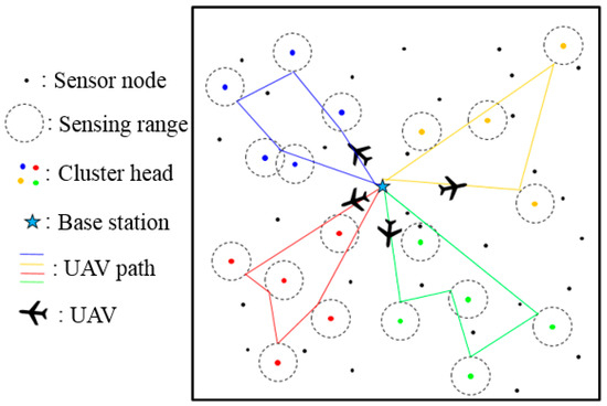
Figure 1.
System model.
Figure 2 shows the structure of the system considered in this study. There are four levels in the structure. Sensor nodes in level 1 transmit their data to the CH node in level 2, and the UAVs in level 3 collect data by visiting the CH nodes and return to the BS, which is level 4. It is assumed that each sensor node has equivalent amount of data and that data of the CH node are proportional to the number of assigned sensor nodes.
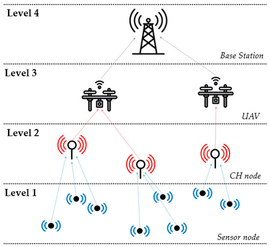
Figure 2.
Structure of the system.
4. Improved K-Means Clustering Algorithm
To divide the mission area of each UAV, the clustering steps are performed three times, as shown in Figure 3.
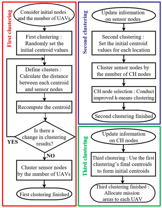
Figure 3.
Improved k-means clustering algorithm flow chart.
4.1. First Clustering
The first step in the clustering algorithm is to distribute the sensor nodes by area, as shown in Algorithm 1. Since the number of regions is defined by the number of UAVs, the sensor nodes are clustered by the k-means clustering algorithm. If there are n UAVs, the location of each sensor node is updated to one of {1, 2, …, n − 1, n}. This step provides the information to apply an improved k-means clustering algorithm in the second and third clustering steps.
| Algorithm 1. First clustering. |
| Input: (the number of clusters) Output: Location of nodes Method: nodes initial centroids for iteration Determine the location of each node for for end end Recompute the centroids end when there is no change in the centroids |
4.2. Second Clustering: CH Node Selection
The second step in the clustering algorithm involves selecting a CH node among the sensor nodes, as shown in Algorithm 2. The CH node communicates with the UAV by integrating data from other nearby sensor nodes. Thus, the UAV does not need to visit all of the sensor nodes to collect the data; instead, the UAV needs to visit only the CH node. Based on the result of the first clustering step, the initial centroid is appropriately distributed for each sensor node. The sensor node that is closest to the final centroid value determined through this improved k-means clustering is selected as the CH node. Since the selected CH nodes are evenly distributed across the entire area for each location, it is possible to prevent overloading missions on any UAV, which would be inefficient in terms of task allocation. In addition, since the final centroid value exists even when a determined CH node cannot be used, it is possible to flexibly replace the sensor node closest to the final centroid by selecting it as a CH node.
| Algorithm 2. Second clustering. |
| Input: (the number of clusters) Location of each sensor node Output: Data of the CH nodes Method: CH nodes initial centroids each location Run Algorithm 1 } Select the nodes closest to final centroids as the CH nodes Update the data of the CH nodes if the lifetime of the selected CH node is exceeded Replace the CH node with the second closest node |
4.3. Third Clustering
The third step in the clustering algorithm is the final process of dividing the mission areas of the UAVs, as shown in Algorithm 3. The selected CH nodes are clustered by the number of UAVs. The k-means clustering algorithm is improved by setting the final cluster center of the first clustering result as the initial cluster center of the third clustering step. Compared with an algorithm with a randomly generated initial cluster center, this can reduce algorithm repetition and improve performance.
Existing k-means clustering algorithms randomly generate the initial cluster centroids. Thus, many iterations are required to obtain reliable results, and the algorithm has a relatively long execution time. In addition, the CH node has large location variability because the clustering results vary greatly depending on the location of the initial centroid. Therefore, an improved k-means clustering algorithm is used in this study, which improves the initial centroid value in the second and third clustering steps.
| Algorithm 3. Third clustering. |
| Input: Output: The mission area for each UAV Method: UAVs Set k initial centroids as the final centroids of the first } for iteration Determine the location of each node for for end end Recompute the centroids end when there is no change in the centroids |
5. Path Planning and Waypoint Refinement Iteration Algorithm
5.1. UAV Path Planning
When the mission area of each UAV is determined, the basic task of the UAV is to depart from the BS, visit the CH nodes to collect data, and then return to the BS. The waypoints that the UAVs must visit are determined by the CH nodes in the mission area. Since the starting and ending points are both at the BS, this can be considered as a Multiple Traveling Salesman Problem (MTSP). Thus, all possible routes can be calculated to determine the shortest path.
5.2. Sensing Range
Each CH node has its own sensing range, and the UAV can communicate with any CH node within that range. The UAV does not necessarily have to hover above the CH node; the UAV can collect data by entering the sensing range of the CH node. The sensing range is an important environmental variable that indicates the performance of the UAV. The greater the sensing range of the CH node, the wider its communication range with the UAV. This is directly related to the performance of the UAV, as the sensors mounted on the UAV are more advanced. If the sensing ranges of two CH nodes overlap, the UAV can explore the overlapping area and collect data from both CH nodes at the same time. Thus, an effective UAV path can be designed by considering the sensing range of the CH nodes. After the order of the CH nodes to visit is determined via UAV path planning, the waypoint refinement iteration algorithm is applied as a postprocessing operation to reduce the overall flight path by ensuring that the waypoint considers the sensing range.
The task processing time is evaluated by considering not only the flight path of the UAV but also the task of collecting data by communicating with the CH nodes. The task processing speed is also affected by the communication distance between the CH node and the UAV within the sensing range. As the distance between the UAV and the CH node, , decreases, the data transmission speed, , and the task processing speed both increase, as shown in Figure 4a. However, the length of the overall UAV path is reduced when the waypoint is set as far as possible from the CH node, as shown in Figure 4b. Thus, there is a trade-off between adjusting the communication distance between the CH node and the UAV and designing the overall UAV flight path.
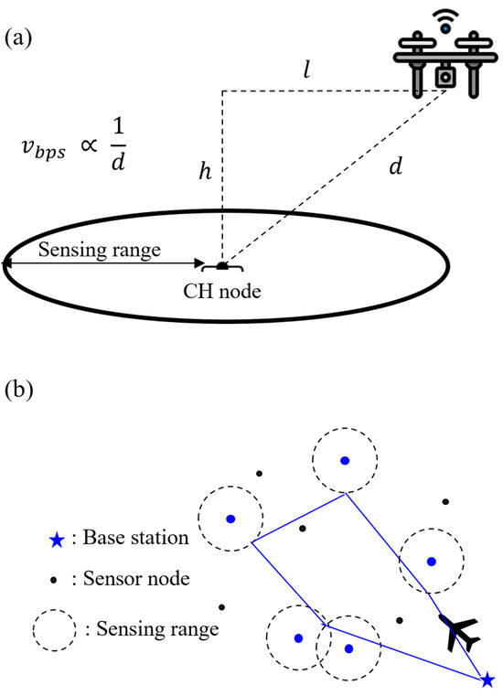
Figure 4.
Trade-off relationship between (a) the communication distance and (b) the overall UAV flight path.
In this study, the time it takes for the UAV to reach the waypoint and the time the UAV spends hovering and collecting data are considered independently. Thus, the task-processing time of the UAV, denoted as , can be evaluated as follows:
where is the total amount of data that the CH node needs to transmit to the UAV, which is proportional to the number of sensor nodes in the same cluster; is the distance-transmission rate inverse constant; is the total flight distance of the UAV; and is the speed of the UAV. The distance between the UAV and the CH node, in Figure 4a, can be obtained by computing the Euclidean distance in the three-dimensional space as follows:
where and are defined in Figure 4a. While the UAV hovers to collect the data, the height of the UAV, , is set to be constant.
5.3. Waypoint Refinement Iteration (WRI) Algorithm
The path of the UAV in the MTSP can be further reduced by considering the sensing range. The path of the UAVs above the CH nodes can be redesigned by setting a point in the sensing range as the waypoint. A triangle that connects each CH node can be created, and a new waypoint can be obtained by calculating the shortest distance with Equations (3)–(6). The algorithm iteratively proceeds until there are no changes in the location of the waypoint.
As shown in Figure 5, there are two cases. In Figure 5, is the distance between points and , which can be calculated as follows:
where and are the x- and y-coordinates of point , respectively. The same definition applies to and . Let us draw a circle centered at point with a radius of :
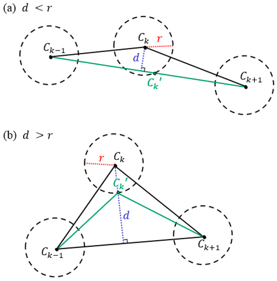
Figure 5.
Two examples of the waypoint refinement iteration algorithm.
Additionally, a line connecting and can be calculated as
Figure 5a depicts d > r. In this case, intersects the circle described in Equation (4) at two points. The points and can be obtained by solving Equations (4) and (5). Of the two points, the point closer to is set as a new waypoint, , as shown in Figure 4a. On the other hand, Figure 5b shows a case where is larger than . In this case, does not intersect the circle described in Equation (4). Instead, a line that is perpendicular to and crosses is considered, as shown in Figure 5b. In this case, the point where the line intersects the circle described in Equation (4) is set as a new waypoint, , with the following equation:
The task-processing time of the UAV regarding the new waypoint can be computed using Equation (1). The detailed procedure is summarized in Algorithm 4.
| Algorithm 4. Waypoint refinement iteration. |
| Input: Order of visiting each CH node The flight path of each UAV passing the CH nodes Output: Updated waypoint The final flight path of each UAV Method: Draw the sensing range (circle) of each CH node Decide the order of the n CH nodes that the UAV must visit = BS for for k = 2 to n − 1 = sensing range if d < r Among the points where the sensing ranges of intersect, the point closest to is set as the new waypoint otherwise Draw a line that is perpendicular to The point where the line and the sensing range intersect is set as the new waypoint end end if there is no further change |
6. Performance Analysis
Numerical simulations are performed to verify the proposed algorithm, and the environment variable settings are shown in Table 1. A total of 500 sensor nodes are randomly placed in a 1000 m × 1000 m field environment. Among them, 100 CH nodes are selected, and the sensing range of each node is 20 m. The number of sensor nodes and CH nodes in Table 1 are set to the same values as in [12] to compare the results.

Table 1.
Parameter list.
6.1. Improved K-Means Clustering Results
To analyze the contribution of the improved k-means clustering algorithm, simulations are conducted to compare the algorithm with previous work [12] in sensor placement scenarios 1 and 2.
6.1.1. Scenario 1
Figure 6 shows a comparison of the clustering results of sensor placement scenario 1, in which the sensor nodes are equally distributed around the area. As shown in Figure 6a, the previous algorithm [12] simply divides the mission area of the UAV into four squares. However, the improved k-means clustering method determines the mission area more efficiently by considering the distribution of the sensors, as shown in Figure 6b. This occurs because the mission area is distributed according to the densities of the sensor nodes.
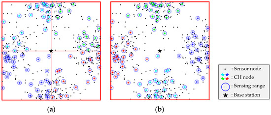
Figure 6.
Comparison of clustering results in Scenario 1: (a) previous work [12], (b) improved k-means clustering.
A performance index, denoted as , is introduced to facilitate a comparative evaluation of the proposed algorithm in relation to the prior algorithm [12]. The computation involves determining the center of the CH nodes for each UAV mission area by averaging their positions. Subsequently, the distance between the computed center and each CH node is calculated, and the average of these distances is represented as . This performance index serves as a measure of the proximity of CH nodes to each other within the same mission area. In Table 2, the values of for Scenario 1 are presented. The reduced average value of , which is achieved through the utilization of the improved k-means clustering method, indicates that the UAV’s path can be effectively shortened.

Table 2.
Performance analysis of Scenario 1 using .
6.1.2. Scenario 2
Sensor placement scenario 2 considers an environment with an unbalanced sensor distribution, as shown in Figure 7. This unbalanced distribution may occur if a unique purpose, such as a cluster sensor placement environment, is considered. The previous algorithm [12] includes too many sensors in specific zones, resulting in unfair task allocation among the UAVs, as shown in Figure 7a. However, the proposed algorithm distributes the mission areas equally among the UAVs, as shown in Figure 7b. The proposed method is effective and robust to uneven sensor distribution. Consistent with Scenario 1, in this scenario, computed using the improved k-means clustering method is found to be smaller than that derived from the prior algorithm [12], as indicated in Table 3.
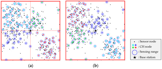
Figure 7.
Comparison of clustering results in Scenario 2: (a) previous work [12], (b) improved k-means clustering.

Table 3.
Performance analysis of Scenario 2 using .
6.1.3. Number of UAVs
If there is an odd number of UAVs or the number of UAVs increases, it becomes difficult to distribute the areas geographically with the previous algorithm [12]. However, as shown in Figure 8, the proposed algorithm can be applied in a variety of situations regardless of the number of UAVs.
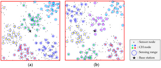
Figure 8.
Clustering result of the proposed algorithm in terms of the number of UAVs: (a) 5 UAVs, (b) 6 UAVs.
6.1.4. Contribution of the Improved K-Means Clustering Algorithm
Figure 9 shows the CH node selected by the third clustering step and the previous clustering step in the improved k-means clustering in Scenario 1. The mission areas of the four UAVs are distributed near the CH nodes, as indicated by the different colors.
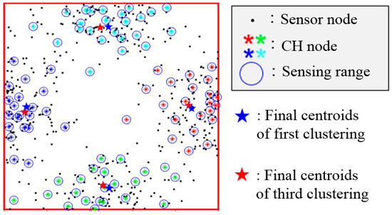
Figure 9.
Comparison of the centroids in the improved k-means clustering algorithm.
The centroids are indicated by the red and blue star shapes in each mission area. The blue star represents the initial centroid of the third clustering step, which is generated by applying the improved k-means clustering algorithm. This is also the final centroid of the first clustering step. The red star represents the final centroid of the third clustering step. Note that the blue and red stars are near each other in each cluster. This effectively reduces the number of iterations of the k-means algorithm. Additionally, the number of CH nodes is evenly divided; thus, UAVs with similar capabilities have fairly allocated mission areas.
6.2. Results of the Waypoint Refinement Iteration Algorithm
6.2.1. Efficiency of the UAV Flight Path
To verify the performance of the waypoint refinement iteration algorithm, a simulation in a simple environment is conducted. The design parameters used in this simulation are listed in Table 4.

Table 4.
Parameter list for WRI algorithm.
Figure 10 shows the results of the UAV flight path before and after applying the waypoint refinement iteration algorithm in this environment. The blue path (227.45 m) is the path taken by the UAV as it passes through the CH node, while the green path (187.66 m) is the path where the algorithm is applied once. The length of the flight path can be effectively reduced by considering the sensing range of the CH nodes instead of hovering above the CH nodes. The red path (186.26 m) is the final path, where the algorithm is applied repeatedly until the path converges. The red path also considers the overlapping area of the sensing ranges to reduce the number of waypoints. Data can be collected from two CH nodes simultaneously at waypoint No. 5 of the red path in Figure 10, whereas the blue and green paths collect the data at waypoint No. 5 and No. 6, respectively. This reduces not only the path length but also the task completion time.
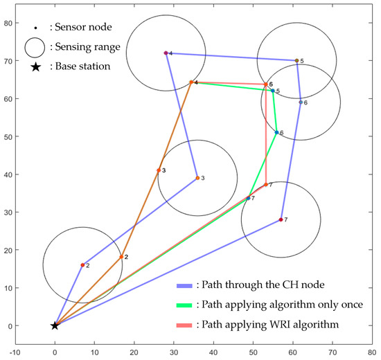
Figure 10.
Comparison of UAV flight paths before and after applying the WRI algorithm.
6.2.2. Consideration of the UAV Data Collection Task
The proposed waypoint refinement iteration algorithm is then applied in an environment that considers the task of the UAV collecting data by communicating with each CH node; the parameters of the environment are listed in Table 5.

Table 5.
Parameters for UAV data collection task.
The number of CH nodes is set to 32, and the rest of the parameters are equivalent to those in Table 1. Based on the scale of the environment and the type of UAV, the flight speed of the rotary-wing UAV is set to 10 m/s. In addition, the capacity of each sensor node is set to 1 MB in accordance with the flash memory of the wireless network-based sensor [2]. Depending on the distance between the CH node and the UAV, the transmission speed varies linearly from 2 Mbps to 40 Mbps.
Figure 11a shows the task completion time, which considers the UAV’s task of collecting data by communicating with each CH node in the waypoint refinement iteration algorithm. In Figure 11b, the red flight path is the result of the previous algorithm [9], while the blue flight path is the result of the waypoint refinement iteration algorithm. The path lengths of the UAVs are shown in Table 6, and the values are not considerably different. When the UAV uses the proposed algorithm to communicate with the CH node, the path length increases slightly due to the trade-off between the communication speed and the overall path. However, the task completion time is substantially faster, as shown in Figure 11a.
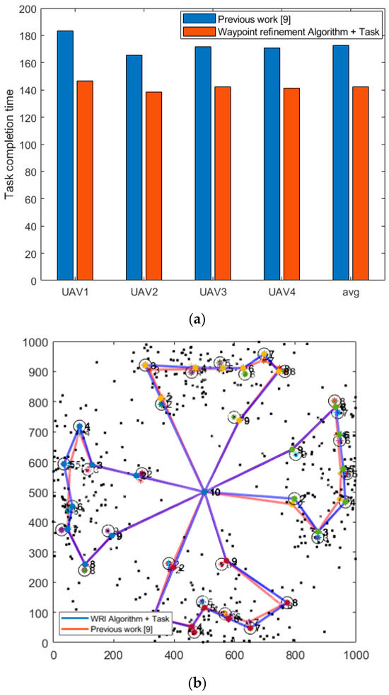
Figure 11.
Comparison between the WRI algorithm and previous work [9]: (a) task completion time, (b) UAV flight path.

Table 6.
Comparison of the UAV path length between the WRI algorithm and previous work [9].
6.3. Performance Analysis in Terms of the Flight Distance of All UAVs
Figure 12a–c show the UAV flight path generated using the previous algorithm [12], the improved k-means clustering algorithm, and the improved k-means clustering algorithm with the waypoint refinement iteration algorithm, respectively. The black dots indicate the sensor nodes, while the asterisks represent the selected CH nodes. The sensing range of each node is indicated by a blue circle. In Figure 12a, the mission area of the UAV is simply divided into four squares around the BS. The algorithm is applied only up to the second clustering to determine the flight path based on the UAV’s mission area distribution. Figure 12b shows the UAV flight path with the mission area determined by the improved k-means clustering algorithm. To compare the results with those of previous work [12], the environmental variables shown in Table 5 are used in both cases. The mission area is distributed more effectively in terms of the placement of the sensor nodes in Figure 12b than in Figure 12a. Additionally, the tasks are fairly allocated, as the number of CH nodes passing through each UAV is equivalent. In Figure 12c, the green path shows the final UAV flight path integrating both the improved k-means clustering algorithm and the waypoint refinement iteration algorithm, which considers the sensing range. The flight path is improved by resetting the waypoint of the UAV to a point within the sensing range. The path length determined with the WRI algorithm is the shortest, as shown in Figure 12d. The path efficiency can be calculated using the following equation.
where the reference path is the total path length of all the UAVs using the previous work [12]. When compared with [12], the improved k-means clustering algorithm improves the path efficiency by approximately 23%. Furthermore, when compared with [12], the improved k-means clustering algorithm with waypoint refinement, which considers the sensing range, improves the path efficiency by approximately 31%. The proposed algorithm reduces the length of the UAV flight path and efficiently distributes the mission areas of multiple UAVs.
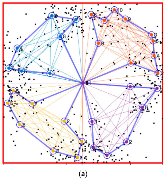
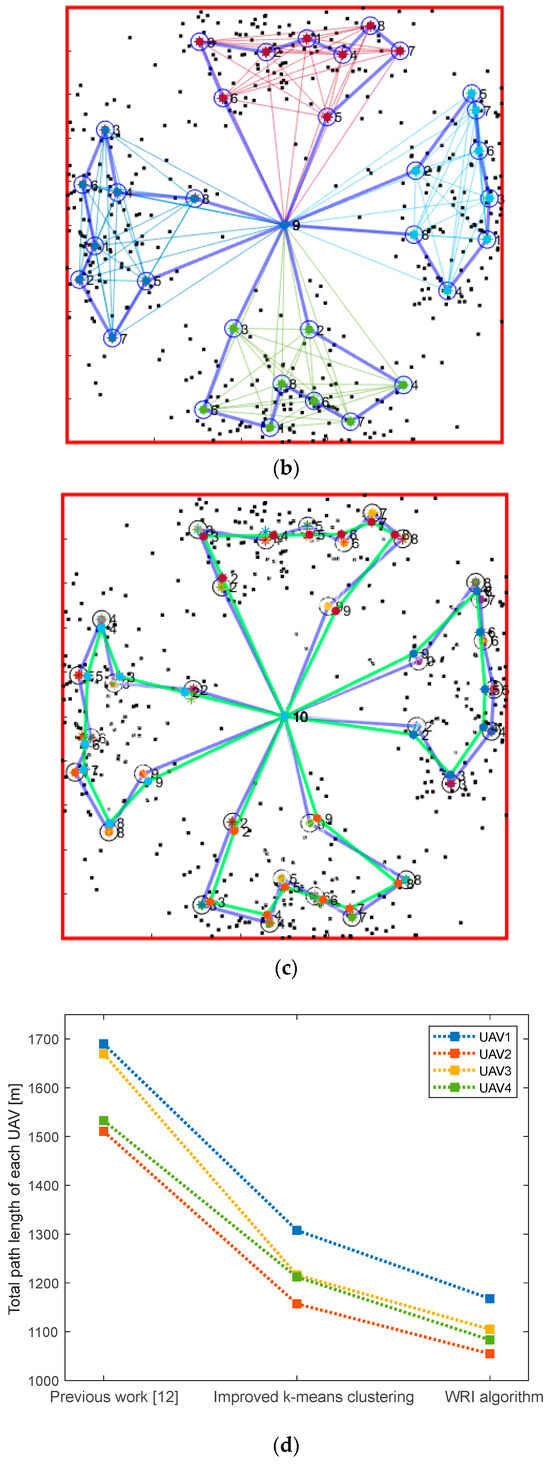
Figure 12.
Performance comparison with Scenario 1: (a) previous work [12], (b) improved k-means clustering, (c) improved k-means clustering with the WRI algorithm, (d) total path length of each UAV.
6.4. Performance Analysis in Terms of the Sensing Range
It is necessary to analyze the performance of the proposed algorithm in terms of the sensing range. The design parameters listed in Table 5 are used, except for the sensing range. Figure 13 shows the path efficiency of Equation (7) with the sensing range varying from 5 m to 30 m. As the sensing range increases, the lengths of all four UAV paths decrease, and the waypoint refinement iteration algorithm performs better.
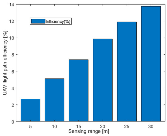
Figure 13.
Path efficiency with respect to the sensing range.
7. Conclusions
In this paper, an improved k-means clustering algorithm that effectively distributes the mission area of UAVs based on the distribution of sensors with various densities is proposed. The mission area can be distributed according to the arrangement of the sensor nodes regardless of the number of UAVs used. In addition, compared with previous work, the proposed k-means clustering algorithm reduces the amount of iterative computation and distributes the tasks evenly among the UAVs. After path planning, a waypoint refinement algorithm is proposed to redesign the waypoint of the UAVs by considering the sensing range. The path length of the UAV can be effectively reduced by adjusting the visiting range of the UAV based on the sensing range. The task of collecting data by communicating directly with the CH node is also considered. By considering the trade-off between the communication time and the overall UAV path, the UAV task completion time can also be reduced. Finally, an integrated framework that divides the mission area of UAVs, determines the most efficient UAV flight path through path planning, and maneuvers along the sensor nodes to collect information is proposed.
Although the number of sensor nodes and CH nodes is fixed in this study to facilitate comparison with previous work [12], the improved k-means clustering algorithm can be further developed by considering the appropriate number of CH nodes to ensure data collection according to the placement of the sensor nodes. In addition, by considering the movement of the UAV in three-dimensional space, it is possible to design a flight path that is similar to the actual movement of the UAV. Accordingly, the WRI algorithm can also be extended to consider the sensing range in a three-dimensional hemisphere. A failure of data transmission due to its instability can also be considered in the integrated framework. In this case, it becomes imperative for the UAVs to demonstrate the capability of dynamic real-time mission area distribution and path replanning. Such an adaptive approach will involve the exclusion of malfunctioning CH nodes, thus ensuring the robustness of data transmission in the UAV’s mission process.
Author Contributions
Conceptualization, S.K. and J.P.; methodology, S.K. and J.P.; software, S.K.; validation, S.K. and J.P.; formal analysis, J.P.; investigation, S.K.; resources, S.K. and J.P.; data curation, S.K. and J.P.; writing—original draft preparation, S.K.; writing—review and editing, J.P.; visualization, S.K.; supervision, J.P.; project administration, J.P.; funding acquisition, J.P. All authors have read and agreed to the published version of the manuscript.
Funding
This work was supported by the National Research Foundation of Korea (NRF) grant funded by the Korea government (MSIT) (No. 2021R1G1A1003429).
Conflicts of Interest
The authors declare no conflict of interest.
Abbreviations
| Parameter | Description |
| -th node | |
| C | Set of the sensor nodes |
| Final centroids of C | |
| Distance between the UAV and the CH node | |
| Data transmission speed | |
| Task processing time of the UAV | |
| Total amount of data | |
| Distance-transmission rate inverse constant | |
| Total flight distance of the UAV | |
| Speed of the UAV |
References
- Popescu, D.; Stoican, F.; Stamatescu, G.; Ichim, L.; Dragana, C. Advanced UAV–WSN System for Intelligent Monitoring in Precision Agriculture. Sensors 2020, 20, 817. [Google Scholar] [CrossRef] [PubMed]
- Karray, F.; Jmal, M.W.; Garcia-Ortiz, A.; Abid, M.; Obeid, A.M. A Comprehensive Survey on Wireless Sensor Node Hardware Platforms. Comput. Netw. 2018, 144, 89–110. [Google Scholar] [CrossRef]
- Ebrahimi, D.; Sharafeddine, S.; Ho, P.; Assi, C. UAV-Aided Projection-Based Compressive Data Gathering in Wireless Sensor Networks. IEEE Internet Things J. 2019, 6, 1893–1905. [Google Scholar] [CrossRef]
- Monwar, M.; Semiari, O.; Saad, W. Optimized Path Planning for Inspection by Unmanned Aerial Vehicles Swarm with Energy Constraints. In Proceedings of the 2018 IEEE Global Communications Conference (GLOBECOM), Abu Dhabi, United Arab Emirates, 9–13 December 2018; pp. 1–6. [Google Scholar]
- Suman, S.; Kumar, S.; De, S. UAV-Assisted RFET: A Novel Framework for Sustainable WSN. IEEE Trans. Green Commun. Netw. 2019, 3, 1117–1131. [Google Scholar] [CrossRef]
- Popescu, D.; Dragana, C.; Stoican, F.; Ichim, L.; Stamatescu, G. A Collaborative UAV-WSN Network for Monitoring Large Areas. Sensors 2018, 18, 4202. [Google Scholar] [CrossRef] [PubMed]
- Modares, J.; Ghanei, F.; Mastronarde, N.; Dantu, K. UB-ANC Planner: Energy Efficient Coverage Path Planning with Multiple Drones. In Proceedings of the 2017 IEEE International Conference on Robotics and Automation (ICRA), Singapore, 29 May–3 June 2017; pp. 6182–6189. [Google Scholar]
- Cabreira, T.; Brisolara, L.; Ferreira, P.R., Jr. Survey on Coverage Path Planning with Unmanned Aerial Vehicles. Drones 2019, 3, 4. [Google Scholar] [CrossRef]
- Chang, W.L.; Zeng, D.; Chen, R.C.; Guo, S. An Artificial Bee Colony Algorithm for Data Collection Path Planning in Sparse Wireless Sensor Networks. Int. J. Mach. Learn. Cybern. 2015, 6, 375–383. [Google Scholar] [CrossRef]
- Akyildiz, I.F.; Su, W.; Sankarasubramaniam, Y.; Cayirci, E. Wireless Sensor Networks: A Survey. Comput. Netw. 2002, 38, 393–422. [Google Scholar] [CrossRef]
- Thammawichai, M.; Baliyarasimhuni, S.P.; Kerrigan, E.C.; Sousa, J.B. Optimizing Communication and Computation for Multi-UAV Information Gathering Applications. IEEE Trans. Aerosp. Electron. Syst. 2018, 54, 601–615. [Google Scholar] [CrossRef]
- Chawra, V.K.; Gupta, G.P. Multiple UAV Path-Planning for Data Collection in Cluster-based Wireless Sensor Network. In Proceedings of the 2020 First International Conference on Power, Control and Computing Technologies (ICPC2T), Raipur, India, 3–5 January 2020; pp. 194–198. [Google Scholar]
- Sun, Y.; Chen, J.; Du, C.; Gu, Q. Path Planning of UAVs Based on Improved Clustering Algorithm and Ant Colony System Algorithm. In Proceedings of the 2020 IEEE 5th Information Technology and Mechatronics Engineering Conference (ITOEC), Chongqing, China, 12–14 June 2020; pp. 1097–1101. [Google Scholar]
- Baek, J.; Han, S.I.; Han, Y. Energy-Efficient UAV Routing for Wireless Sensor Networks. IEEE Trans. Veh. Technol. 2020, 69, 1741–1750. [Google Scholar] [CrossRef]
Disclaimer/Publisher’s Note: The statements, opinions and data contained in all publications are solely those of the individual author(s) and contributor(s) and not of MDPI and/or the editor(s). MDPI and/or the editor(s) disclaim responsibility for any injury to people or property resulting from any ideas, methods, instructions or products referred to in the content. |
© 2023 by the authors. Licensee MDPI, Basel, Switzerland. This article is an open access article distributed under the terms and conditions of the Creative Commons Attribution (CC BY) license (https://creativecommons.org/licenses/by/4.0/).