Article

Jet Engine Turbine Mechanical Properties Prediction by Using Progressive Numerical Methods

Faculty of Aeronautics, Technical University of Košice, Rampová 7, 04 121 Košice, Slovakia
*
Author to whom correspondence should be addressed.
Aerospace 2023, 10(11), 937; https://doi.org/10.3390/aerospace10110937
Submission received: 13 August 2023 / Revised: 25 October 2023 / Accepted: 30 October 2023 / Published: 1 November 2023

Abstract

:
The propulsion system for an aircraft is one of its most crucial systems; therefore, its reliable work must be ensured during all operational conditions and regimes. Modern materials, techniques and methods are used to ensure this goal; however, there is still room for improvement of this complex system. The proposed manuscript describes a progressive approach for the mechanical properties prediction of the turbine section during jet engine operation using an artificial neural network, and it illustrates its application on a small experimental jet engine. The mechanical properties are predicted based on the measured temperature, pressure and rpm during the jet engine operation, and targets for the artificial neural network are finite element analyses results. The artificial neural network (ANN) is trained using training data from the experimental measurements (temperatures, pressure and rpm) and the results from finite element analyses of the small experimental engine turbine section proposed in the paper. The predicted mechanical stress by ANN achieved high accuracy in comparison to the finite element analyses results, with an error of 1.38% for predicted mechanical stress and correlation coefficients higher than 0.99. Mechanical stress and deformation prediction of the turbine section is a time-consuming process when the finite element method is employed; however, the method with artificial neural network application presented in this paper decreased the solving time significantly. Mechanical structural analyses performed in ANSYS software using finite element modeling take around 30–40 min for one load step. In contrast, the artificial neural network presented in this paper predicts the stress and deformation for one load step in less than 0.00000044 s.

1. Introduction

The failure of jet engines has been an issue since the early days of aviation. Extensive research on material science has ensured improvement in the field of mechanical strength and extended the life of jet engine parts [1,2,3]. Mainly, parts in the hot section of a jet engine are subjected to high loads due to the high temperatures, centrifugal forces, etc. [4]. The critical part is the high turbine section where all the above-mentioned loads are applied [5,6]. The extreme heat emitted by the combustion exhaust gases has a major impact on the turbine disc and blades stress and turbine life properties. To ensure high strength of the turbine parts, the proper materials with high-performance material properties such as Young’s modulus and thermal expansion coefficient have to be used [7]. There are many scientific papers investigating the material properties impact on the operational mechanical characteristics of gas turbines [8,9]. The progress in material science is focused on progressive materials, for example, materials such as superalloys and thermal barrier coatings that are used in gas turbines; these are described in many scientific articles [10,11,12].
The progress in material science is one of the ways in which aviation safety can be increased; another is an appropriate novel design of the aircraft or jet engine parts. The history of aviation shows that the accurate and proper design of the aircraft and jet engine parts is one of the crucial parameters in terms of safe aircraft operation. Jet engine malfunction and failure can cause disaster. In the study of an aircraft engine high-pressure turbine (HPT) first stage blade, the authors claimed that almost 50% of failures are located in the damage of turbine blades and discs [13]. There are also other studies that have pointed out the design of the aircraft parts, showing that an impropriate design can cause aircraft parts failure [1,14,15,16]. There are many numerical and experimental ways for improving aircraft engine reliability during development; however, it is essential to also monitor the strength of the aircraft parts and their reliability during the operation [17,18].
During the operation of particular parts of the aircraft, they have to be properly monitored. Nowadays, jet engines use modern software for health monitoring, which are parts of the FADEC (full authority digital engine control) that are mainly used for engine control [19,20]. The FADEC systems perform many functions in modern jet engines, for instance, functions of gas generators such as the control of fuel flow, acceleration and deceleration; control of turbine clearance; idle settings; etc. FADEC also ensures protection against the engine exceeding the limits in terms of overspeed, power management, automatic engine starting sequence, manual engine starting sequence, thrust reverser control, etc. For these functions, FADEC uses many inputs gained from the sensors built into the jet engine that monitor the temperatures, pressures, rpm, altitude, Mach number, physical fan speed, physical core speed, ratio of fuel flow, corrected fan speed, corrected core speed, burner fuel–air ratio, etc. In [21], the authors use 24 monitored inputs for their FADEC study; the result of their research was the remaining life of the turbofan engine. These measured parameters could be used to predict the mechanical properties. There have been several studies on mechanical properties prediction, for example, one of them described the stress prediction of the compressor disc-drum and the process of selecting and optimizing the artificial neural network [21]. In [22], the remaining useful life was predicted by the neural network. In [23], the authors used an artificial neural network (ANN) for fatigue life prediction of a steam turbine rotor. The trend in the jet engine industry is to use new algorithms for controls and methods application and new materials such as composites for the fan section; special alloys for the compressor, combustion chambers and turbines, etc. The presented paper combines modern mathematical approaches to create methods suitable for modern engine health and mechanical strength monitoring.
The mechanical properties, namely deformation and stress, can serve as the inputs for the remaining fatigue life prediction of a jet engine and can be used as a supplementary parameter for health monitoring [23,24]. The main novelty of this paper is devoted to the methodology, which represents the application of ANNs to predict the mechanical properties of the turbine section. The surrogation of the finite element method (FEM) for the mechanical properties prediction of the turbine section based on ANNs is used. The FEM replacement by ANNs and its application on jet engines represent a modern approach. The surrogate model is well known for its design optimization but not in the monitoring of the jet engine [25]. The surrogate model used for monitoring health is the main novelty of the proposed paper. There have already been many studies that have shown the fact that an ANN consumes less time than FEM analysis [26,27,28]; therefore, it is a suitable approach for jet engine health monitoring rather than FEM.
The hypothesis is to create a surrogate model of the jet engine turbine section using the FEM results for mechanical deformation and stress prediction for jet engine health monitoring in a short time and to use the results almost in real time. The main goal is to create/use the methodology for a turbine surrogation model that can be used in further research. The main goal of the methodology is to create a novel mathematical model for the turbine section that will predict mechanical properties immediately during jet engine operation based on the measured temperatures, rpm and pressures. The following sections present the results of the study, the application of the methodology and its application on a particular small jet engine, iSTC-21v [29].

2. Materials and Methods

The study presented in this paper focuses on the prediction of mechanical stress and deformation in a small jet engine. The novelty of the study is mainly in the prediction of mechanical deformation and stress using an ANN during the jet engine operation. The mechanical properties are predicted almost in real time, so the engine health can be monitored using the actual data immediately.

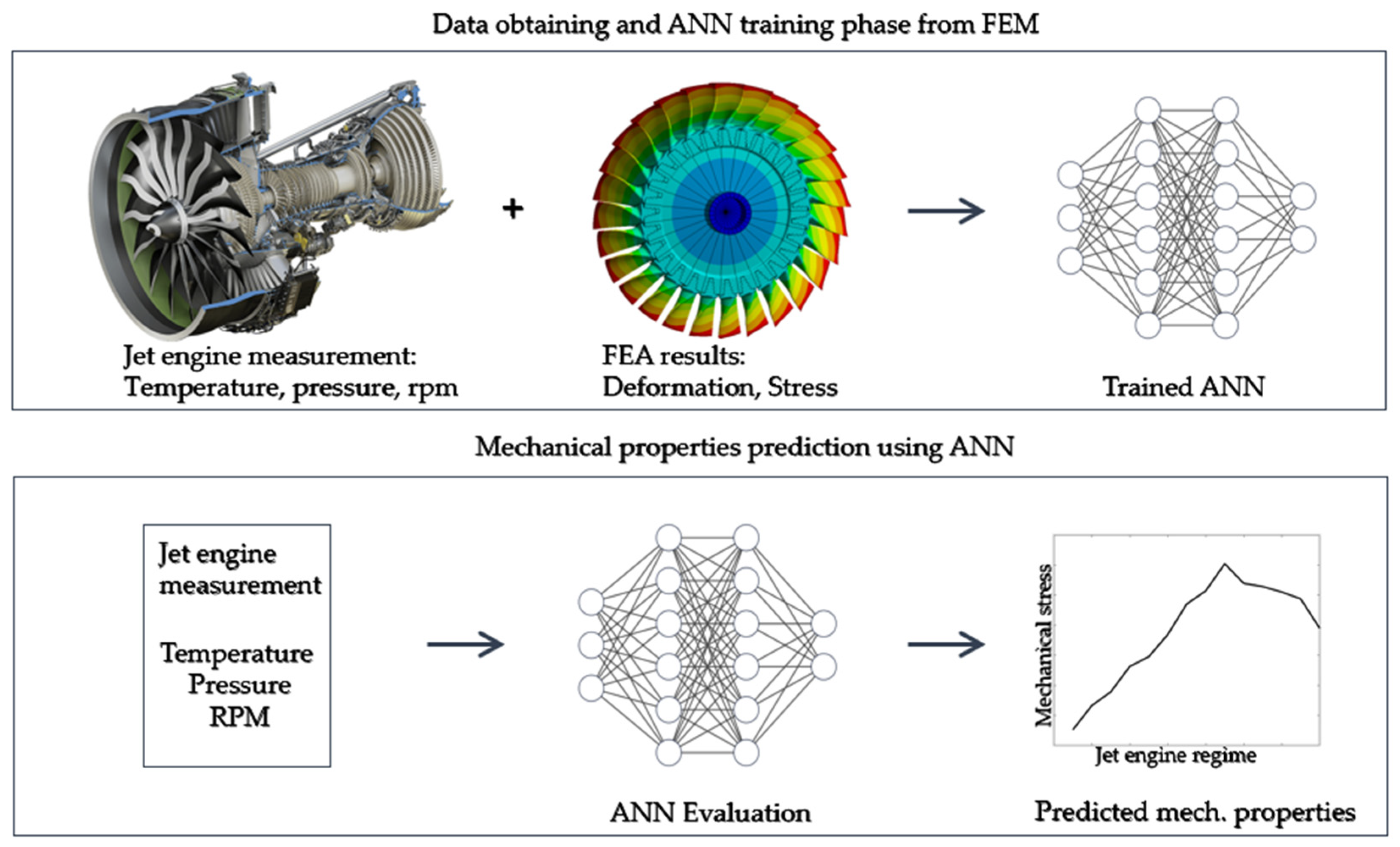
2.1. The Methodology for Deformation and Stress Prediction

The FEM model predicts mechanical deformation and stress as a function of temperature, pressure and rpm, as prescribed in the FEM model. The FEM boundary conditions are based on the coupled aero-structural CFD analyses. This means that, for each regime according to the measured temperatures and pressures, CFD analyses are carried out to calculate the temperature and pressures in the turbine section. CFD analysis results are mapped into the FEM analyses using ANSYS software. The FEM model is evaluated for 70 different operating regimes of the experimental engine. The FEM model results are used for training and validation of the ANN. In the running jet engine, the temperatures, pressure and rpm are measured, and with these measured values, the trained ANN is used to predict stress quickly, almost in real time. In other words, the ANN surrogate model is a result of the FEM model data. The methodology is presented in Figure 1.
The methodology is applied to a small experimental jet engine, iSTC-21v (Figure 2) [29]. The jet engine is a single-shaft engine with one stage of centrifugal compressor, combustion chamber and one stage of axial turbine.

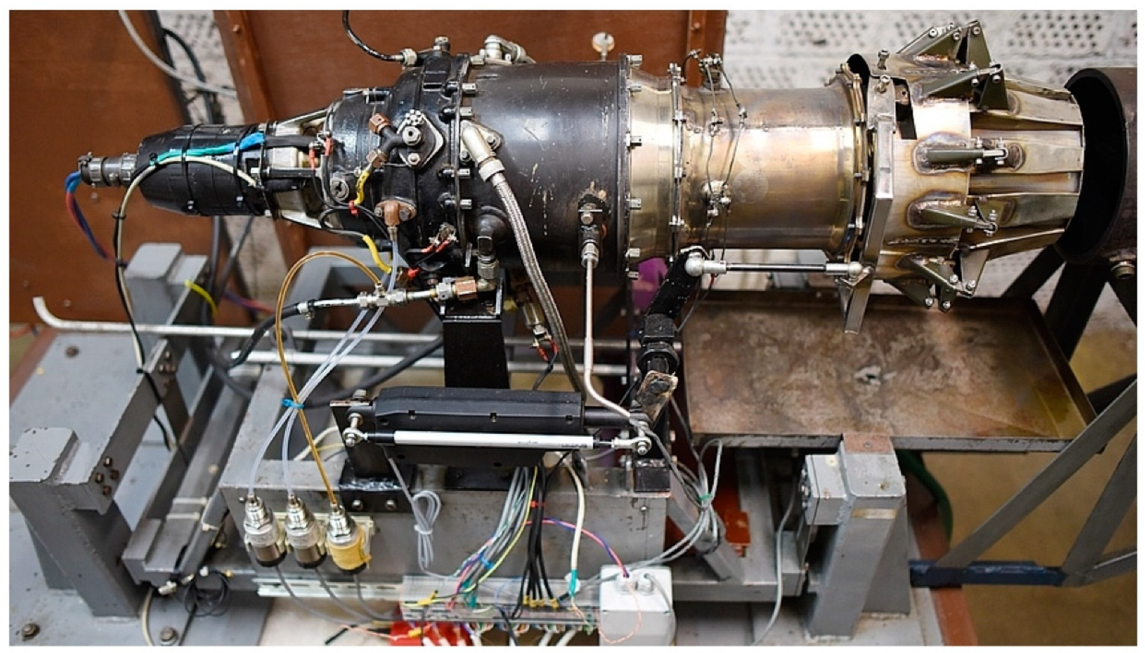
2.2. The Object of Interest: Small Jet Engine iSTC-21v

In this subsection, the object of interest is presented; it is a small experimental single-shaft jet engine, with one stage of centrifugal compressor, combustion chamber and one stage of turbine. The jet engine has a variable exhaust nozzle. The engine on a test bench is used under laboratory conditions, as shown in Figure 2.
Figure 3 shows the measurement points of the iSTC-21v jet engine during the engine testing run, and the following basic engine parameters were measured:
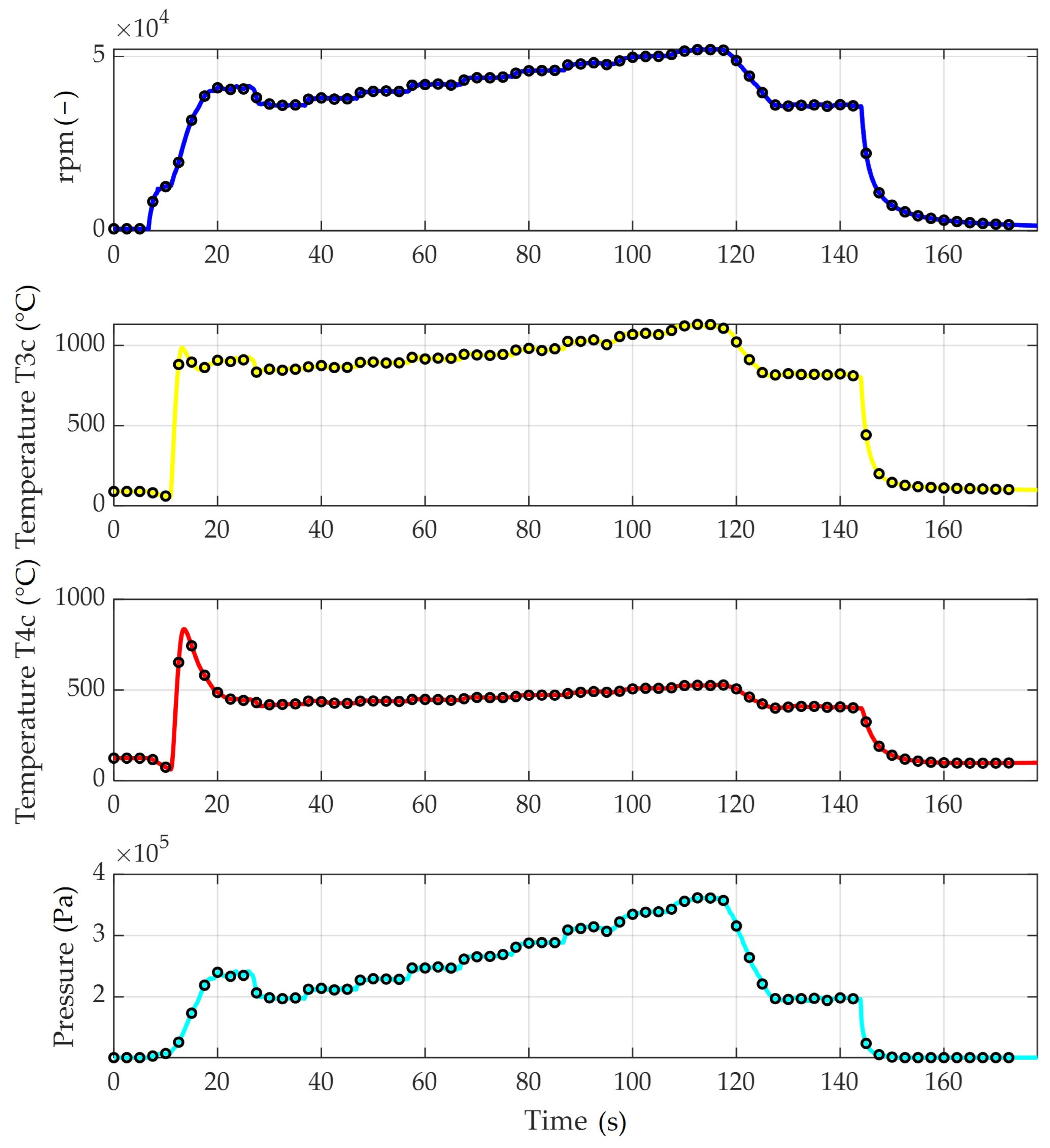
  • Outside air temperature T0 (°C) and atmospheric pressure P0 (Atm).
  • Total air temperature at the inlet of the radial compressor T1C (°C).
  • Total air temperature at the outlet from the diffuser of the radial compressor T2C (°C).
  • Total gas temperature at the inlet of the gas turbine T3C (°C).
  • Total gas temperature at the outlet of the gas turbine T4C (°C).
  • Total pressure of air at the outlet of the compressor P2c (Atm).
  • Total pressure of gases at the inlet of the gas turbine P3c (Atm).
  • Fuel flow supply FF (1/min).
  • Thrust Th (kg).
  • Shaft speed of the turbine/compressor, n1 (rpm).
  • Exhaust nozzle diameter A5 (mm) [29,30].
In the presented surrogate model, the temperature T3c, pressure P3c, temperature T4c and rpm are used.
One single run that takes almost 3 min (178 s) is shown in Figure 4, where the rpm, temperatures T3c and T4c and pressure P3c are plotted. In Figure 4, 70 regimes are shown from the run according to each regime, and these values are used as boundary conditions for the analyses. The CFD analysis is performed to calculate the impact of temperatures and pressure on the turbine [5]. The results from the CFD are mapped in transient thermal analyses to calculate the temperature fields. These transient thermal analyses define the relationship between temperatures, pressures and mechanical stress. Transient thermal analysis results are used in mechanical stress analyses for 70 regimes (black dots on lines in Figure 4), and 35 regimes are used for training the surrogate ANN model and 35 for its validation.

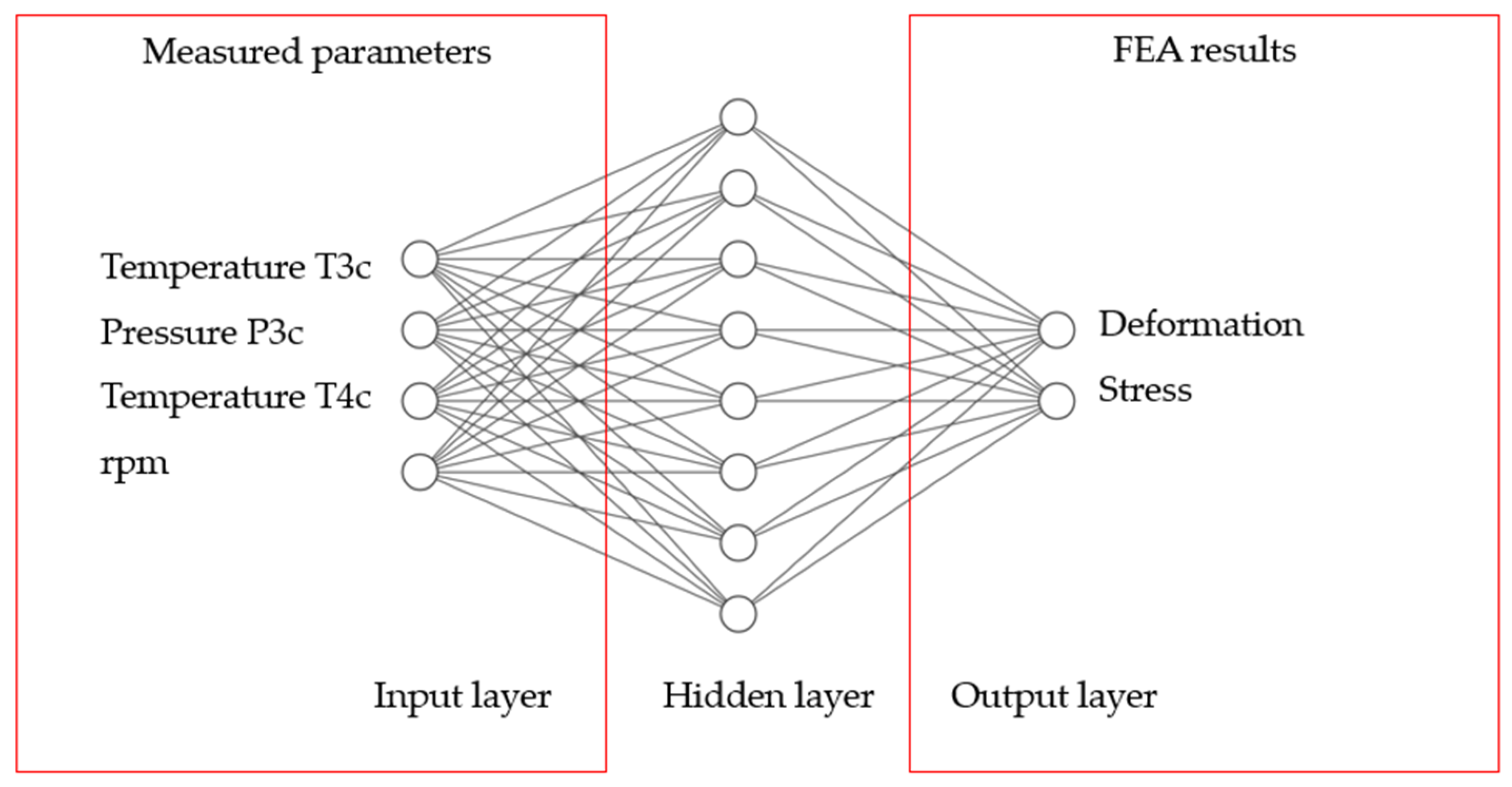
2.3. The Finite Element Models and ANN Surrogate Model Description

The FEM model of the turbine section is created using ANSYS Workbench 2022 [31] software, and it is shown in Figure 5. The turbine section consists of the turbine disc, turbine blades and fir tree root; for the FEA (finite element analysis) purposes, the cyclic region is extracted (Figure 5) in order to make the solution process faster and more efficient. Thus, the FEM consists of a single-blade cyclic region of a turbine blade, disc and lock. The boundary conditions (BCs) are applied according to the specific operational regimes of the iSTC-21v jet engine. The cyclic symmetry is defined by the pre-meshed cyclic region (shown in red in Figure 5) [25]. The turbine section is divided into 27 regions. The rotational velocity is defined in a cylindrical coordinate system according to the measured rpm during the experimental measurement, and it is shown by a red arrow in Figure 5. The axial movement is eliminated by 0 displacement in the axis, simulating the attachment of the turbine disc into the jet engine rotor shaft.
The FEA are performed using ANSYS Workbench software for the 70 operational regimes of the jet engine. For the FEA results illustration, one regime is postprocessed: ANSYS APDL [31], which is presented in the result section of this paper.
The ANN is developed and trained using the FEA results and experimentally measured rpm, temperatures and pressures (input layer) using MATLAB software [32] (Figure 6). The calculated FEA results, mechanical deformation and stress, are used in the output layer. The architecture consists of one input layer with four neurons, one hidden layer with ten neurons and one output layer with two neurons, and the ANN is shown in Figure 6. In the input layer, the four neurons represent the measured rpm, temperature and pressure of the iSTC-21v jet engine. The output layer has two neurons that represent the mechanical properties (mechanical stress and deformation of turbine) that are obtained from the FEA simulations in ANSYS Workbench.
In the study, the scaled conjugate gradient backpropagation training algorithm is used in order to train the surrogate model. As the training algorithm is scaled, a conjugate gradient (SCG) for the supervised learning is used. This algorithm updates the weight and bias values according to the scaled conjugate gradient method [33,34,35]. The algorithm is able to train any ANN as long as its weight, net input and transfer functions have derivative functions. In order to calculate derivatives of the performance with respect to the weight and bias variables x, backpropagation was used [36].
The inputs (Figure 6, input layer) for the ANN measured from the experimental run of a small experimental engine are shown in Table 1. The output layer consists of the FEA results, namely mechanical deformation and mechanical stress (Figure 6). The first column in Table 1 is the operational regime or load step, the second column represents the measured rpm, the third column stands for the measured turbine section temperatures—T3c and the fourth column is last of the three measured parameters. The fourth column is the measured pressure in the turbine section. The second part of the inputs in Table 1 are the results from the FEAs, so the total maximal deformation in mm and the maximal von Mises stress is calculated in MPa. These 35 regimes are used for the ANN training process and are shown in Table 1, and the other 35 regimes in the second half of Figure 4 are used to compare predicted results by a surrogate ANN model and FEM deformations and stresses.

3. Results

The results are partially represented by FEA results and partially by the results from the ANN training and mechanical stress predicting processes.

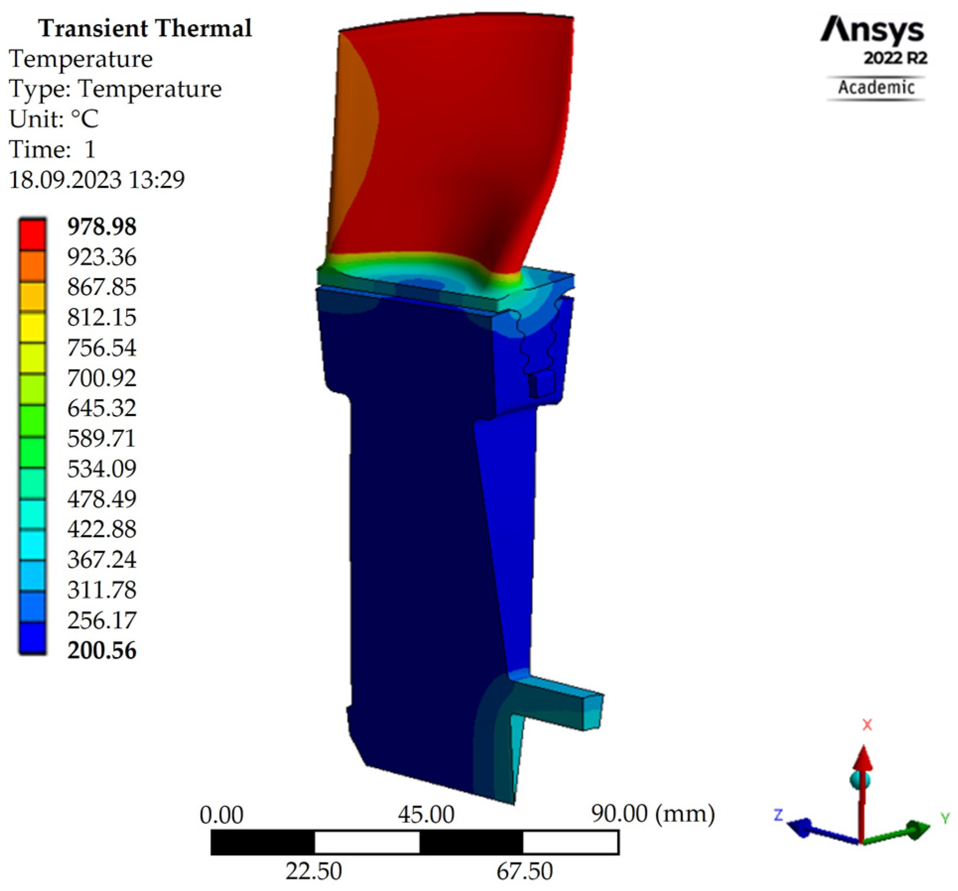
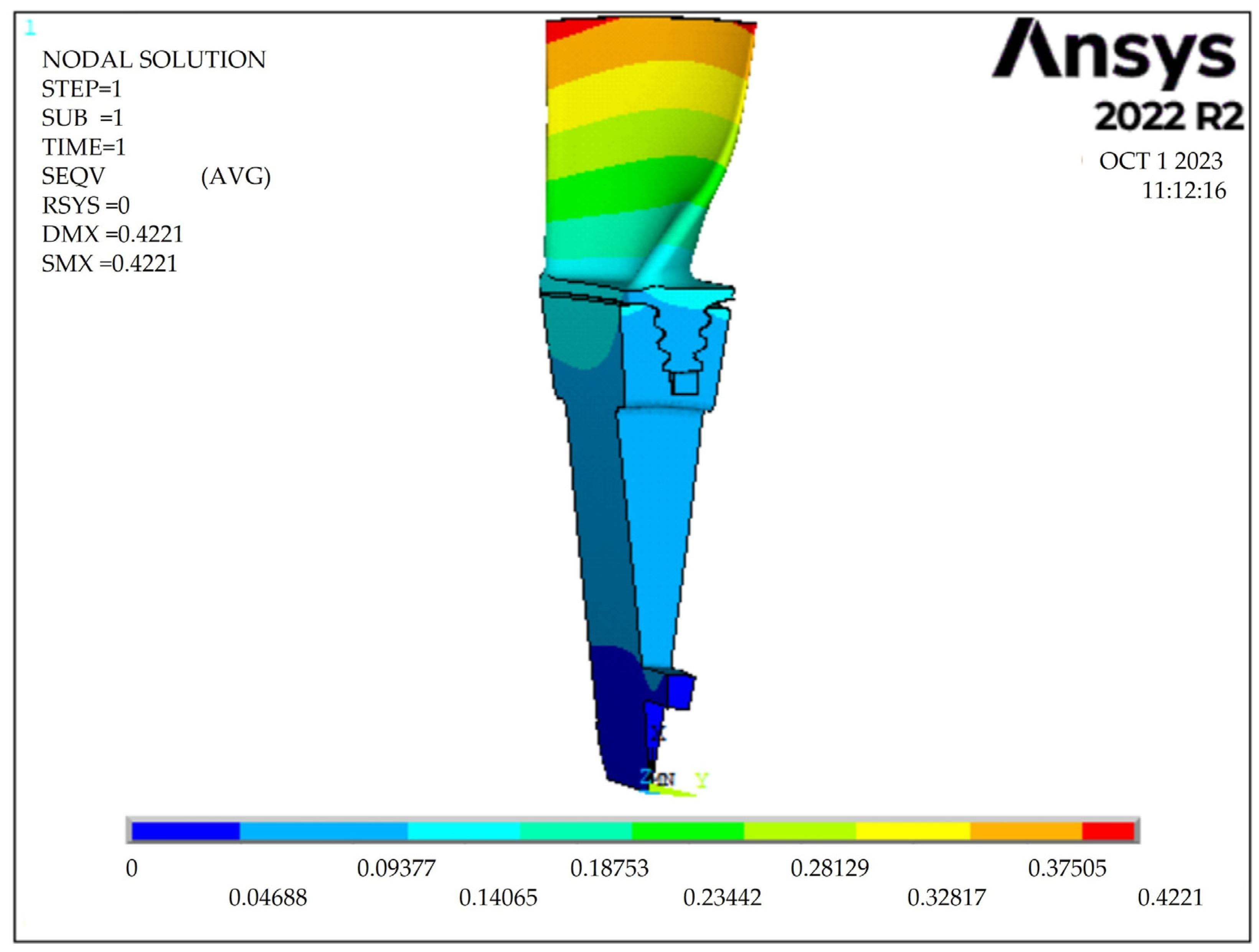
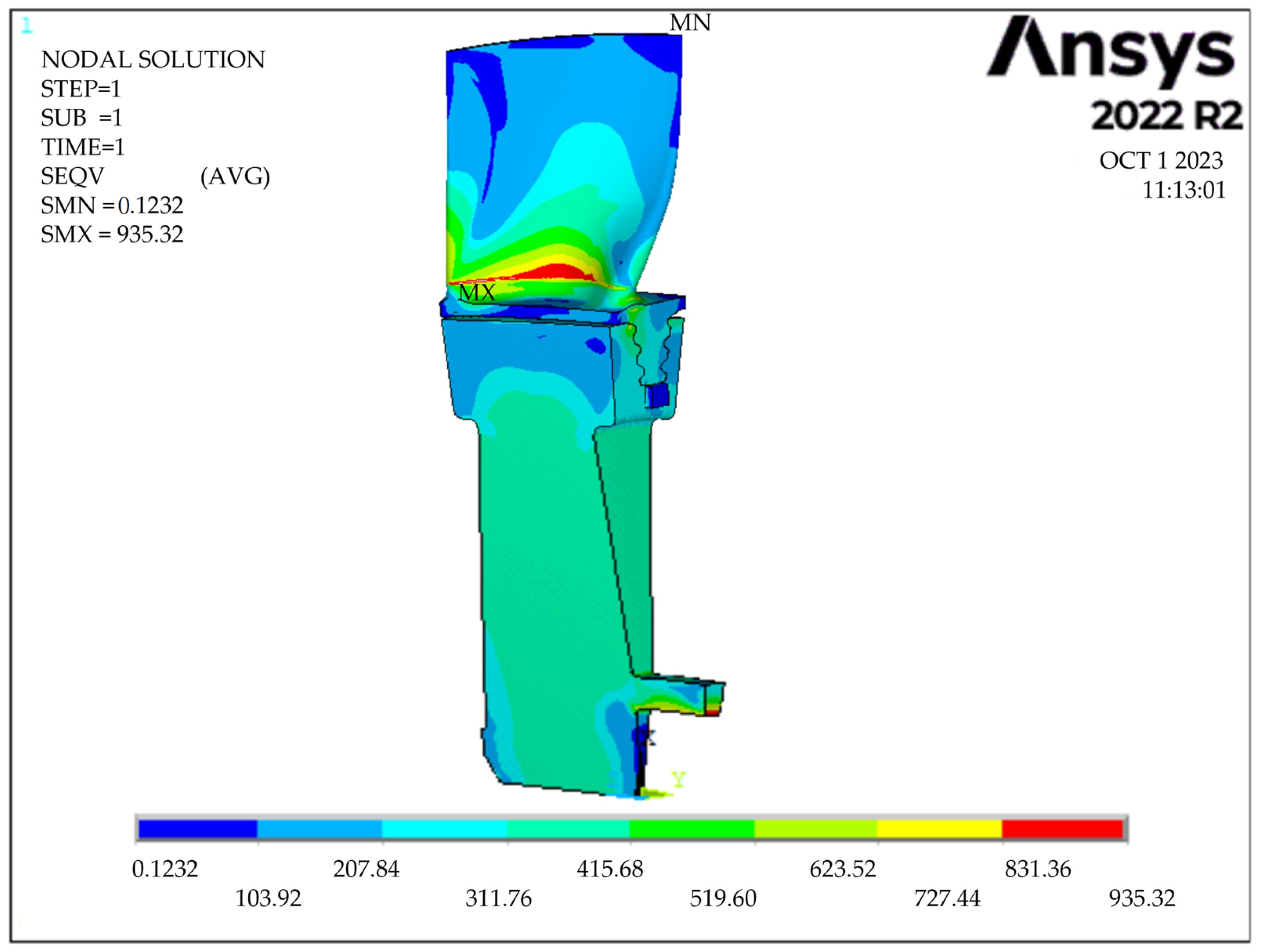
3.1. The Finite Element Analyses of the iSTC-21v Turbine Section

As already mentioned, the mechanical stress and total deformation from the static structural analysis are calculated for seventy regimes, and three of these regimes are described below. The CFD analyses are performed to define the relationship between the temperatures, pressures and mechanical properties (deformations and stresses). The results are mapped using ANSYS software, and transient thermal analyses are performed (Figure 7); the results from these thermal analyses are used for the mechanical stress analyses. Regime 35 is used to illustrate the results of the transient thermal analyses for one cyclic region [33]. In Figure 7, the temperature fields can be seen for regime 35. The solution time for the transient thermal analysis for one load step is 18.9 min.
The FEA method is used to calculate mechanical deformation and stress for each regime, and the results are used as an input for the ANN surrogate model. The total deformation for the first regime is 0.4221 mm (Figure 8). The maximum von Mises stress calculated by the ANSYS is 935.32 MPa (Figure 9). The solution time for the mechanical stress analysis for one load step is 26.11 min. The solution time for one load step together with the transient thermal analysis is 45.01 min and, for 70 regimes, is 52.51 h.

3.2. ANN with Scaled Conjugate Gradient Backpropagation for Mechanical Properties Prediction

For the mechanical properties, the ANN with scaled conjugate gradient backpropagation algorithms is trained using MATLAB software, as described in the Materials and Methods section; in the following subsection, the results of the study are presented.
The scaled conjugate gradient backpropagation training algorithm is selected for the mechanical properties prediction. The ANN is described in Figure 6, and the results of the training process are represented in Figure 10; the plot is also called a regression plot. Figure 10 shows the relationship between the outputs of the training process and the targets. In order to summarize the ANN inputs presented in Figure 6, the inputs in the input layer are measured parameters during the engine experimental run: T3c, P3c, T4c and rpm, while in the output layer are the results of the FEA, the calculated maximal deformations and maximal mechanical stresses; in other words, the targets are the maximal stress and displacement values. The training data are shown in Table 1 and are divided into three groups: 70% of the data is for the training process, 15% is for the validation and 15% belongs to the test process. The dividerand function is used in MATLAB software to divide the input data for training, validation and the test process [37]. Normalization of the inputs and targets is performed in MATLAB software using the mapminmax function [38,39]. The R value or coefficient of correlation is an important factor when the training process is investigated, as it is an indication of the linear dependance between the outputs and targets. The exact linear relationship between the outputs and targets is indicated when the R value is equal to 1. If the R value is equal to the 0, then there is no relationship between the outputs and the targets.
The R values are shown in Figure 10. The training data have an R value of 0.99988. The R value for the validation process is 0.99986, the test process has an R value of 0.99989 and all the data are represented by an R value of 0.99987.
The trained ANN is used for mechanical stress and total deformation prediction, as is shown in Figure 6. The results are compared between the calculations from the FEM results calculated in ANSYS and the ANN trained using MATLAB software. In the following figures, the mechanical deformation and mechanical stress are compared between the FEA results and ANN results. The maximal deformation predicted by NN for 70 operational regimes is shown in Figure 11 with a black line, and the brick-colored line is the plotted FEM results. The red vertical line divides the dataset into two parts: first, from 1 to 35, the FEM results were also used for the ANN training process, and second, from 35 to 70, the regimes were used for comparison between the FEM and ANN.
A more detailed view of the predicted mechanical deformations for 35 regimes is shown in Figure 12. The comparison was made between the FEA results and the ANN surrogate model.
Figure 13 represents the errors calculated between the FEA results and predicted results using the surrogate ANN model; the maximal error for deformation occurs in regime 63, and its value is 3.74%. As can be seen in Figure 13, the majority of the results are below 2%, apart from five regimes.
Errors in mm for the deformations are calculated between the FEA and ANN results, and these values are shown in Figure 14. The maximal difference is in regime 63, which is 0.009 mm.
The ANN surrogate model, apart from deformations, also predicts the maximal mechanical stresses of the turbine section. As already mentioned, the model is trained based on the FEA results and measured parameters (Table 1). A comparison of the study is shown in Figure 15, where the maximal stresses from the analyses and maximal stresses from the ANN surrogate model can be seen. There are 70 regimes calculated in Figure 12: 35 regimes are used to train the ANN and 35 regimes to validate the results (comparing the FEM and ANN results). The ANN predicted the mechanical properties for the whole engine run for the 70 regimes in 0.00003 s. The red vertical line divides the dataset into two parts: first, from 1 to 35, the FEM results were also used for the ANN training process, and second, from 35 to 70, the regimes are used for comparison between the FEM and ANN.
Figure 16 shows detail only on regimes 35–70, where the dependance between the FEA results and ANN can be seen.
Errors of the maximal stresses between the FEA and ANN results are in Figure 17. The maximal percentage error reaches 2.57%.
The maximal difference between the maximal FEA mechanical stress and maximal stress calculated by the ANN surrogate model occurs in regime 12 and has a value of 19.21 MPa, as can be seen in Figure 18.

4. Conclusions

The presented study in the paper shows the results of the progressive method for mechanical properties prediction of the turbine section. During jet engine operation, it is essential to ensure reliable work of the turbine section; in order to fulfil this requirement, the jet engine’s health in terms of the maximal temperatures, pressures, rpms and mechanical stresses have to be monitored. The results presented in this manuscript show a new approach in terms of mechanical stress and deformation monitoring of the turbine section. As already discussed in this manuscript, several methods have been applied for the creation of a novel method for turbine stress mechanical properties prediction using an ANN. The following statements can be expressed based on the results.
  • Seventy FEM models were created, and 35 results were used for the training process of the ANN.
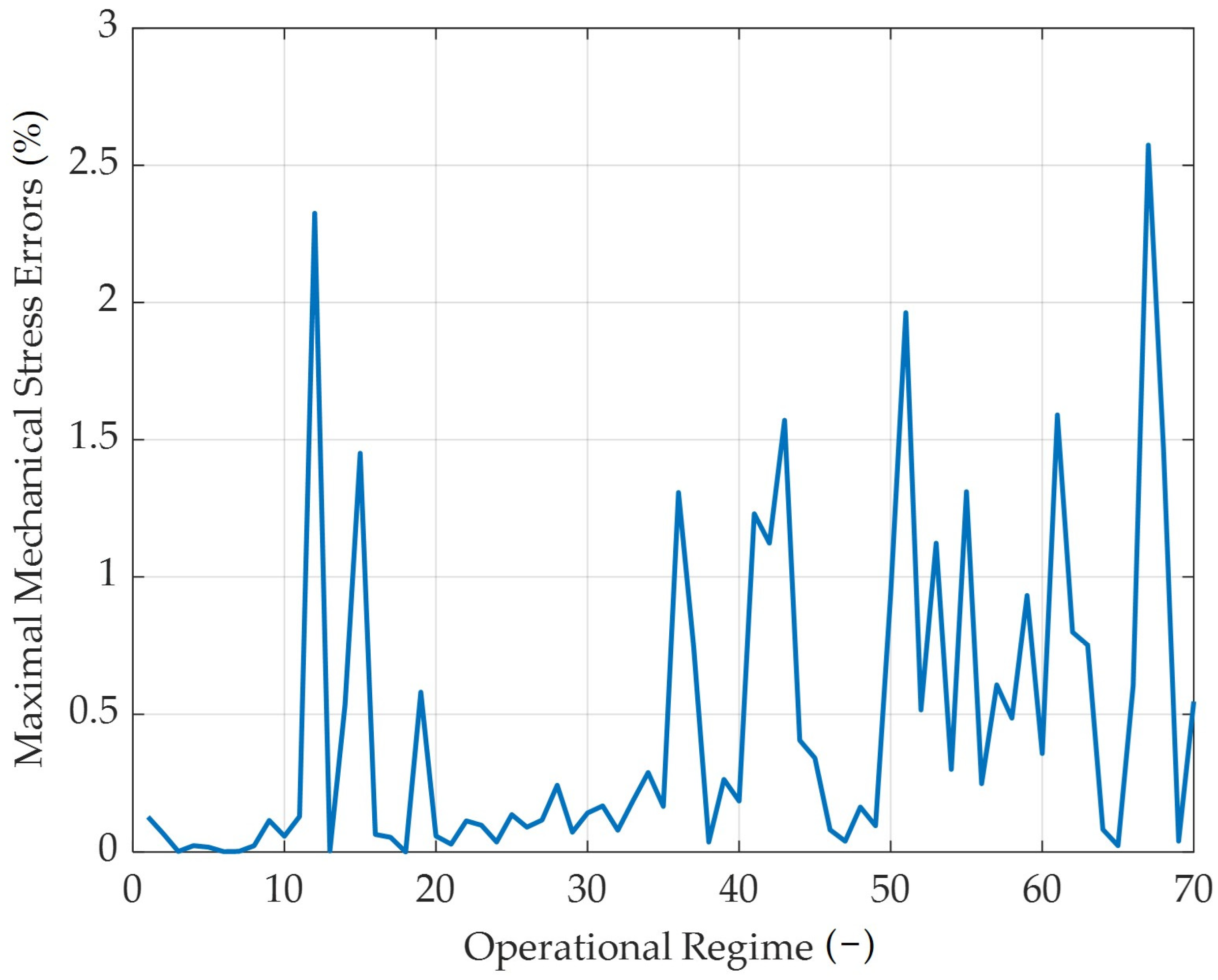
  • The best training algorithm for the ANN and mechanical stress prediction is the scaled conjugate backpropagation (SCG) algorithm. As shown in Figure 9, the maximal error is 2.57% for the predicted mechanical stress. The ANN with SCG algorithm predicts the maximal deformation with a maximal error of 3.74%.
  • The hypothesis stated in the Introduction section that it is possible to predict mechanical properties using a surrogate model trained based on the FEA results has been confirmed. Based on the results, it is possible to proclaim a quite accurate match between the surrogate model and FEA results in deformation and stress prediction. The accuracy of the prediction is also supported by the high R values (every R value is higher than 0.99), as shown in Figure 11.
  • In future research, the results should be validated using experimental stress and strain measurements; however, main goal of this paper was to apply numerical methods in a 3D turbine section cyclic region to create preliminary surrogate models. According to the measured temperatures, pressures and rpm, CFD models were created, and the results were mapped into the mechanical analyses in order to define the relationship between these parameters and the calculated stress.
  • It is possible to apply the trained ANN into the FADEC system and monitor mechanical stress and deformation during jet engine operation, which ensures a higher level of safety. This method also surrogates on some level the FEM analysis, which is not able to predict mechanical stress as fast as the ANN. The ANN predicted the mechanical properties for the whole engine run for 70 regimes in 0.00003 s; thus, one regime is predicted by the ANN in a fraction of a second. In comparison, FEA takes several hours for the prediction of one regime.

Author Contributions

Conceptualization, M.S. and M.H.; methodology, M.S.; software, M.S.; validation, M.S., P.K. and M.H.; formal analysis, M.S.; investigation, M.S.; resources, M.S.; data curation, ization, M.S.; supervision, M.H.; project administration, M.H.; funding acquisition, P.K. All authors have read and agreed to the published version of the manuscript.

Funding

This work was funded by the Slovak Research and Development Agency under number APVV-20-0546—Innovative measurement of airspeed of unconventional flying vehicles and under contract number OPII-VA/DP/2021/9.3-01 within the “Research of an intelligent management logistics system with a focus on monitoring the hygienic safety of the logistics chain” project implemented under contract number 313011BWP9.

Data Availability Statement

The data presented in this study are available upon request from the corresponding author. The data are not publicly available due to privacy restrictions.

Conflicts of Interest

The authors declare no conflict of interest.

References

  1. Mansoor, M.; Ejaz, N. Thermal fatigue failure of fuel spray bars of a jet engine afterburner. Eng. Fail. Anal. 2011, 18, 492–498. [Google Scholar] [CrossRef]
  2. Li, D.; Liu, J.; Sun, Y.; Huang, W.; Li, N.; Yang, L. Microstructure and mechanical degradation of K403 Ni-based superalloy from ultra-long-term serviced turbine blade. J. Alloys Compd. 2023, 957, 170378. [Google Scholar] [CrossRef]
  3. Li, L.; Zeng, Y.; Li, J.; Zhao, Y.; Yuan, T.; Yue, Z. Effect of Crystal Orientation on Elastic Stresses and Vibration Characteristics of Nickel-based Single Crystal Turbine Blade. Mater. Today Commun. 2023, 35, 106135. [Google Scholar] [CrossRef]
  4. Kułaszka, A.; Błachnio, J.; Borowczyk, H. The Impact of Temperature on the Surface Colour of Gas Turbine Blades Heated in the Presence of Kerosene. Aerospace 2023, 10, 375. [Google Scholar] [CrossRef]
  5. Spodniak, M.; Semrád, K.; Draganová, K. Turbine Blade Temperature Field Prediction Using the Numerical Methods. Appl. Sci. 2021, 11, 2870. [Google Scholar] [CrossRef]
  6. Zych, P.; Żywica, G. Fatigue Analysis of the Microturbine Rotor Disc Made of 7075 Aluminium Alloy Using a New Hybrid Calculation Method. Materials 2022, 15, 834. [Google Scholar] [CrossRef]
  7. Sun, Z.; Jiang, X.; Qiu, C.; Cheng, S.; Liu, X.; Li, H.; Liu, X.; Wang, Y.; Dong, J.; Lou, L. The investigations of rejuvenation heat treatment on the microstructure and mechanical properties of a serviced gas turbine blade. J. Alloys Compd. 2023, 948, 169759. [Google Scholar] [CrossRef]
  8. Olufayo, O.A.; Che, H.; Songmene, V.; Katsari, C.; Yue, S. Machinability of Rene 65 Superalloy. Materials 2019, 12, 2034. [Google Scholar] [CrossRef]
  9. Balitskii, A.I.; Kvasnytska, Y.H.; Ivaskevych, L.M.; Kvasnytska, K.H.; Balitskii, O.A.; Shalevska, I.A.; Shynskii, O.Y.; Jaworski, J.M.; Dowejko, J.M. Hydrogen and Corrosion Resistance of Nickel Superalloys for Gas Turbines, Engines Cooled Blades. Energies 2023, 16, 1154. [Google Scholar] [CrossRef]
  10. Yadav, M.; Misra, A.; Malhotra, A.; Kumar, N. Design and analysis of a high-pressure turbine blade in a jet engine using advanced materials. Mater. Today Proc. 2020, 25, 4. [Google Scholar] [CrossRef]
  11. Agüero, A.; Baráibar, I.; Gutiérrez, M.; Tuurna, S.; Toivonen, A.; Penttilä, S.; Auerkari, P. Steam Oxidation of Aluminide-Coated and Uncoated TP347HFG Stainless Steel under Atmospheric and Ultra-Supercritical Steam Conditions at 700 °C. Coatings 2020, 10, 839. [Google Scholar] [CrossRef]
  12. Wee, S.; Do, J.; Kim, K.; Lee, C.; Seok, C.; Choi, B.-G.; Choi, Y.; Kim, W. Review on Mechanical Thermal Properties of Superalloys and Thermal Barrier Coating Used in Gas Turbines. Appl. Sci. 2020, 10, 5476. [Google Scholar] [CrossRef]
  13. García-Martínez, M.; Gordillo, J.; González, M.; Muro, A.; Caballero, B. Failure study of an aircraft engine high pressure turbine (HPT) first stage blade. Eng. Fail. Anal. 2023, 149, 107251. [Google Scholar] [CrossRef]
  14. Mishra, R.K.; Thomas, J.; Srinivasan, K.; Nandi, V.; Bhatt, R.R. Failure analysis of an un-cooled turbine blade in an aero gas turbine engine. Eng. Fail. Anal. 2017, 79, 836–844. [Google Scholar] [CrossRef]
  15. Poursaeidi, E.; Tafrishi, H.; Amani, H. Experimental-numerical investigation for predicting erosion in the first stage of an axial compressor. Powder Technol. 2017, 306, 80–87. [Google Scholar] [CrossRef]
  16. Vo, D.; Mai, T.; Kim, B.; Jung, J.; Ryu, J. Numerical investigation of crack initiation in high-pressure gas turbine blade subjected to thermal-fluid-mechanical low-cycle fatigue. Int. J. Heat Mass Transf. 2023, 202, 123748. [Google Scholar] [CrossRef]
  17. Sakamoto, J.; Tada, N.; Uemori, T.; Kuniyasu, H. Finite Element Study of the Effect of Internal Cracks on Surface Profile Change due to Low Loading of Turbine Blade. Appl. Sci. 2020, 10, 4883. [Google Scholar] [CrossRef]
  18. Badshah, S.; Naeem, A.; Farhan Rafique, A.; Ul Haq, I.; Abdullah Malik, S. Numerical Study on the Critical Frequency Response of Jet Engine Rotors for Blade-Off Conditions against Bird Strike. Appl. Sci. 2019, 9, 5568. [Google Scholar] [CrossRef]
  19. De Giorgi, M.G.; Menga, N.; Ficarella, A. Exploring Prognostic and Diagnostic Techniques for Jet Engine Health Monitoring: A Review of Degradation Mechanisms and Advanced Prediction Strategies. Energies 2023, 16, 2711. [Google Scholar] [CrossRef]
  20. Aghasharifian Esfahani, M.; Namazi, M.; Nikolaidis, T.; Jafari, S. Advanced Control Algorithm for FADEC Systems in the Next Generation of Turbofan Engines to Minimize Emission Levels. Mathematics 2022, 10, 1780. [Google Scholar] [CrossRef]
  21. Kozakiewicz, A.; Kieszek, R. Artificial Neural Network Structure Optimisation in the Pareto Approach on the Example of Stress Prediction in the Disk-Drum Structure of an Axial Compressor. Materials 2022, 15, 4451. [Google Scholar] [CrossRef] [PubMed]
  22. Wang, H.; Li, D.; Li, D.; Liu, C.; Yang, X.; Zhu, G. Remaining Useful Life Prediction of Aircraft Turbofan Engine Based on Random Forest Feature Selection and Multi-Layer Perceptron. Appl. Sci. 2023, 13, 7186. [Google Scholar] [CrossRef]
  23. Zhao, X.; Ru, D.; Wang, P.; Gan, L.; Wu, H.; Zhong, Z. Fatigue life prediction of a supercritical steam turbine rotor based on neural networks. Eng. Fail. Anal. 2021, 127, 105435. [Google Scholar] [CrossRef]
  24. Liu, S.; Chu, J.; Wang, Y. Research on Prediction Method of Bolt Tightening for Aviation Components Based on Neural Network. Appl. Sci. 2023, 13, 6771. [Google Scholar] [CrossRef]
  25. Yan, C.; Yin, Z.; Shen, X.; Mi, D.; Guo, F.; Long, D. Surrogate-based optimization with improved support vector regression for non-circular vent hole on aero-engine turbine disk. Aerosp. Sci. Technol. 2020, 96, 105332. [Google Scholar] [CrossRef]
  26. Quevedo-Reina, R.; Álamo, M.G.; Padrón, A.L.; Aznárez, J.J. Surrogate model based on ANN for the evaluation of the fundamental frequency of offshore wind turbines supported on jackets. Comput. Struct. 2023, 274, 106917. [Google Scholar] [CrossRef]
  27. Hashemi, A.; Jang, J.; Beheshti, J. A Machine Learning-Based Surrogate Finite Element Model for Estimating Dynamic Response of Mechanical Systems. IEEE Access 2023, 11, 54509–54525. [Google Scholar] [CrossRef]
  28. Zhang, C.; Janeway, M. Optimization of Turbine Blade Aerodynamic Designs Using CFD and Neural Network Models. Int. J. Turbomach. Propuls. Power 2022, 7, 20. [Google Scholar] [CrossRef]
  29. Andoga, R.; Főző, L.; Kovács, R.; Beneda, K.; Moravec, T.; Schreiner, M. Robust Control of Small Turbojet Engines. Machines 2019, 7, 3. [Google Scholar] [CrossRef]
  30. Andoga, R.; Főző, L.; Judičák, J.; Bréda, R.; Szabo, S.; Rozenberg, R.; Džunda, M. Intelligent Situational Control of Small Turbojet Engines. Int. J. Aerosp. Eng. 2018, 2018, 8328792. [Google Scholar] [CrossRef]
  31. ANSYS, Inc. ANSYS; ANSYS, Inc.: Canonsburg, PA, USA, 2023; Available online: https://www.ansys.com (accessed on 10 October 2023).
  32. MathWorks. MATLAB, Version 9.12.0 (R2022b); The MathWorks Inc.: Portola Valley, CA, USA, 2023. [Google Scholar]
  33. Pinelli, L.; Lori, F.; Marconcini, M.; Pacciani, R.; Arnone, A. Validation of a Modal Work Approach for Forced Response Analysis of Bladed Disks. Appl. Sci. 2021, 11, 5437. [Google Scholar] [CrossRef]
  34. Annala, L.; Äyrämö, S.; Pölönen, I. Comparison of Machine Learning Methods in Stochastic Skin Optical Model Inversion. Appl. Sci. 2020, 10, 7097. [Google Scholar] [CrossRef]
  35. Draganová, K.; Laššák, M.; Praslička, D.; Kán, V. Attitude-Independent 3-axis accelerometer calibration based on adaptive neural network. Procedia Eng. 2014, 87, 1255–1258. [Google Scholar] [CrossRef]
  36. Khan, F.; Eker, O.F.; Khan, A.; Orfali, W. Adaptive Degradation Prognostic Reasoning by Particle Filter with a Neural Network Degradation Model for Turbofan Jet Engine. Data 2018, 3, 49. [Google Scholar] [CrossRef]
  37. Corte-Valiente, A.D.; Castillo-Sequera, J.L.; Castillo-Martinez, A.; Gómez-Pulido, J.M.; Gutierrez-Martinez, J.-M. An Artificial Neural Network for Analyzing Overall Uniformity in Outdoor Lighting Systems. Energies 2017, 10, 175. [Google Scholar] [CrossRef]
  38. Duan, W.; Song, C.; Peng, S.; Xiao, F.; Shao, Y.; Song, S. An Improved Gated Recurrent Unit Network Model for State-of-Charge Estimation of Lithium-Ion Battery. Energies 2020, 13, 6366. [Google Scholar] [CrossRef]
  39. Ren, X.; Dong, K.; Feng, C.; Zhu, R.; Wei, G.; Wang, C. Application of MLR, BP and PCA-BP Neural Network for Predicting FeO in Bottom-Blowing O2-CaO Converter. Metals 2023, 13, 782. [Google Scholar] [CrossRef]
Figure 1. The methodology for the mechanical properties prediction using numerical methods.
Aerospace 10 00937 g001
Figure 2. Experimental small jet engine iSTC-21v in the laboratory on a test bench [29].
Aerospace 10 00937 g002
Figure 3. Measurement points on the iSTC-21c jet engine [30].
Aerospace 10 00937 g003
Figure 4. Measured parameters during the experimental run of the iSTC21v jet engine.
Aerospace 10 00937 g004
Figure 5. The FEA model with BCs of the iSTC-21v experimental jet engine turbine section.
Aerospace 10 00937 g005
Figure 6. The ANN architecture for mechanical deformation and stress prediction.
Aerospace 10 00937 g006
Figure 7. The transient thermal analysis results.
Aerospace 10 00937 g007
Figure 8. The calculated total deformation of the turbine section iSTC-21v jet engine.
Aerospace 10 00937 g008
Figure 9. The calculated von Mises stress of the turbine section in the iSTC-21v jet engine.
Aerospace 10 00937 g009
Figure 10. The regression plots of the trained ANN with R values.
Aerospace 10 00937 g010
Figure 11. Calculated maximal mechanical deformations using FEA and predicted deformations by the ANN.
Aerospace 10 00937 g011
Figure 12. Predicted maximal deformations by ANN—details view.
Aerospace 10 00937 g012
Figure 13. Calculated percentage errors between the FEA and ANN results.
Aerospace 10 00937 g013
Figure 14. Calculated errors in mm between the FEA and ANN results.
Aerospace 10 00937 g014
Figure 15. Calculated maximal mechanical stresses using FEA and predicted stresses by the ANN.
Aerospace 10 00937 g015
Figure 16. Predicted maximal stresses by ANN—details view.
Aerospace 10 00937 g016
Figure 17. Calculated percentage errors between the FEA and ANN results for stress prediction.
Aerospace 10 00937 g017
Figure 18. Calculated errors in MPa between the FEA and ANN results for stress prediction.
Aerospace 10 00937 g018
Table 1. The measured and calculated inputs for the ANN training process.
RegimeRPMT3cP3cT4cFEA DeformationFEA Stress
155889.30101,289.8124.930.12469.36
255889.25101,290.9124.780.12469.36
355889.25101,285.5124.530.12469.36
4836881.09103,915.3117.080.13783.23
512,66260.55107,964.674.960.14164.87
619,641881.30126,341.9652.550.333667.78
731,746896.22173,515.5744.100.337699.56
838,650862.16218,992.6581.550.375827.38
941,037907.30240,131.1486.710.387849.50
1040,574899.81233,450.1450.140.383842.70
1140,704910.25234,975.5443.150.385844.09
1238,205833.65206,537.3430.950.372826.25
1336,381852.21198,581.7419.180.362783.73
1436,008845.65197,067.2421.010.358775.17
1536,117851.71198,305.2423.880.363794.54
1637,755866.72212,386439.230.371811.97
1738,131874.80213,906.5436.110.373816.07
1837,783862.07211,341.3428.030.371801.87
1937,858863.04212,391427.010.371814.85
2039,624894.53227,341.2439.050.380833.73
2140,029896.94229,540439.900.381837.52
2240,126890.70229,021438.840.380838.44
2339,996891.62228,563.6437.430.380837.35
2441,792925.94247,162.6448.400.394860.81
2541,957915.6124,7095448.610.391859.36
2642,124920.7924,8787.8447.520.393862.45
2741,820919.5224,6957.3443.740.392859.55
2843,256944.9626,1480452.510.407886.22
2943,921940.7426,5423.6459.520.407891.10
3043,916938.0326,6028.8458.270.407890.47
3144,112944.0226,9109.6458.280.411896.31
3245,206971.2428,1054.2464.250.420920.45
3345,926981.8528,7743.2471.740.422934.27
3445,977968.5128,8586.4472.260.421930.91
3546,035979.0728,8518.8472.000.422935.32
Disclaimer/Publisher’s Note: The statements, opinions and data contained in all publications are solely those of the individual author(s) and contributor(s) and not of MDPI and/or the editor(s). MDPI and/or the editor(s) disclaim responsibility for any injury to people or property resulting from any ideas, methods, instructions or products referred to in the content.

