Abstract
A key challenge in flapping-wing micro air vehicle (FWMAV) design is to generate high aerodynamic force/torque for improving the vehicle’s maneuverability. This paper presents a bio-inspired hover-capable flapping-wing micro air vehicle, named RoboFly.S, using a cross-tail wing to adjust attitude. We propose a novel flapping mechanism composed of a two-stage linkage mechanism, which has a large flapping angle and high reliability. Combined with the experimentally optimized wings, this flapping mechanism can generate more than 34 g of lift with a total wingspan of 16.5 cm, which is obviously superior to other FWMAVs of the same size. Aerodynamic force/torque measurement systems are used to observe and measure the flapping wing and aerodynamic data of the vehicle. RoboFly.S realizes attitude control utilizing the deflection of the cross-tail wing. Through the design and experiments with tail wing parameters, it is proved that this control method can generate a pitch torque of 2.2 N·mm and a roll torque of 3.55 N·mm with no loss of lift. Flight tests show that the endurance of RoboFly.S can reach more than 2.5 min without interferences. Moreover, the vehicle can carry a load of 3.4 g for flight, which demonstrates its ability to carry sensors for carrying out tasks.
1. Introduction
Insects and hummingbirds have attracted extensive attention from researchers because of their excellent flight ability. Researchers try to draw inspiration from insects and hummingbirds, study their biological forms and flight mechanisms, and devise micro air vehicles with the same flight ability [,,]. Compared with traditional aircraft, the bionic shape and flight mode of FWMAVs allow them to have extremely high concealment and flight efficiency. They are more suitable for carrying out reconnaissance and detection missions in narrow and complex spaces. Therefore, FWMAVs have broad application prospects in both military and civil fields, and they are also expected to carry out reconnaissance missions in the outer space environment in the future [].
To date, with the development of micro-electro-mechanical systems (MEMSs) and new material processing technology, a variety of FWMAV prototypes imitating insects or hummingbirds have appeared. One of the most representative research projects is the research project of DARPA []. According to the scale and driving mode of the vehicle, FWMAVs can be divided into those driven by motors and those driven by smart material actuators. In terms of FWMAVs driven by smart material actuators, representative vehicles are the MFI devised by the University of California, Berkeley [], the RoboBee series devised by Harvard University [,,], the insect-inspired flapping-wing robot devised by Shanghai Jiaotong University [], the FWMAV of Nanyang Technological University [] and the FWMAV researched by Beihang University []. These FWMAVs based on smart material actuators usually utilize piezoelectric, electromagnetic, and dielectric elastomer actuators as power sources. Their flapping frequencies are generally above 100 Hz, and they have a very small scale and weight. However, controllable flight and independent flight are difficult to achieve at present. Therefore, their control systems and energy systems still require further research.
Researchers have made great progress on FWMAVs driven by motors in the past decade, mainly focusing on their mechanical structure, flight control and aerodynamic optimization. The “Nano Hummingbird” vehicle devised by the AeroVironment company has the aerodynamic shape of a hummingbird and similar flight ability []. Researchers utilize a string-based flapping mechanism and conduct the matching design of wings and power consumption from three aspects: theoretical calculation, experimental optimization and noise tests. “DelFly Nimble” can accurately mimic the rapid escape maneuvers of fruit flies and it utilizes four wings to fly [,,]. The use of the clap-and-fling mechanism greatly improves the aerodynamic force of the vehicle. Moreover, “Colibri” series vehicles have extremely strong hovering ability due to their attitude control model [,,,,]. “KUBeetle-S” series vehicles can hover for 8.8 min with high aerodynamic efficiency [,,]. “NUS-Roboticbirds” have strong mobility and load capacity []. The “Hummingbird” of Purdue University realizes its hovering by utilizing the motion coordination of the motors and the gears [,,]. The National University of Singapore and Beihang University have conducted research on four-winged micro air vehicles with tail wings [,]. These vehicles can realize hovering flight and maneuvering flight and have an excellent bionic shape. In addition, researchers from Carnegie Mellon University also creatively designed a new flying system by using the combination of geared pager motors and elastic elements []. The Nano Hummingbird and the NUS-Roboticbird can even carry a micro camera to perform reconnaissance missions.
In this work, we present a two-winged FWMAV based on a novel flapping mechanism with high lift, and its control mode of a tail wing has greatly improved the hovering stability and attitude torque of the vehicle. RoboFly.S’s flapping mechanism is composed of a two-stage linkage mechanism, which can output a flapping angle of 162°. It can produce the highest lift of more than 34 g, which is obviously superior to other FWMAVs of the same size. Moreover, when the attitudes of tailless FWMAVs are adjusted, the aerodynamic forces of its wings on both sides will change significantly, this mode requires the vehicle to generate more aerodynamic force to maintain its attitude. However, RoboFly.S utilizes the cross-tail wing to adjust its attitude, while the max angle of attack (AoA) of the wing and the waveform for the AoA variations are fixed in flight. That means its lift remains unchanged and it does not need to generate extra aerodynamic force to maintain its attitude. This control method decouples the aerodynamic force and attitude torque of the vehicle, reduces the interaction between force and torque, and reduces the difficulty of control. Most importantly, this control mode can produce pitch torque of 2.2 N·mm and roll torque of 3.55 N·mm, which helps to improve the mobility of vehicle.
The rest of this paper is organized as follows: Section 2 summarizes the overall system design, lift generation, and control method. Section 3 details the onboard circuit design and flight control. Section 4 presents the experimental validation and flight tests. Finally, Section 5 summarizes this work.
2. System Design and Optimization
2.1. System Overview
In this section, we introduce the design and optimization of the vehicle, including the flapping mechanism, the bionic-wing optimization experiments, and the control mode. The FWMAV designed in Figure 1 has a total weight of 24.8 g, a wingspan of 16.5 cm, and a height of 18 cm. It has a maximum lift of up to 34 g and endurance of 2.5 min. The vehicle adopts the control mode of cross-tail wing to maintain its stability of attitude and flight maneuverability, and utilizes the linkage mechanism as the flapping mechanism to drive two wings, generating high lift. The mechanical structure is made of nylon and carbon fiber to improve strength and reduce the weight of the fuselage. The vehicle mainly includes a flapping mechanism, a frame, motors, servos, an autopilot, a battery, bionic wings, and a tail wing, as shown in Figure 1. The parameters of the vehicle are shown in Table 1.
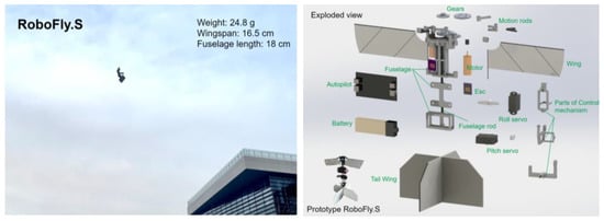
Figure 1.
Prototype RoboFly.S.

Table 1.
The parameters of RoboFly.S.
2.2. Flapping Mechanism
The flapping mechanism designed in this paper takes the delayed-stall mechanism as the main lift mechanism and utilizes the clap-and-fling mechanism of some insects as the aerodynamic source of the vehicle.
The design of the flapping mechanism mainly meets the following objectives: (1) To improve the transmission efficiency of the mechanism and reduce the power consumption of the mechanism, with the minimum transmission angle ≥ 40° []; (2) To reduce the size of the flapping mechanism and improve the compactness, with the fuselage width limited to 30 mm; (3) To increase the lift-weight ratio of the aircraft and use the clap-and-fling mechanism to improve lift, so that the flapping amplitude should be close to 180°; (4) To ensure the symmetry of the period and phase of forward and backward flapping, eliminate the quick-return characteristics, and to achieve a uniform distribution of lift.
In this scheme, the crank-rocker and swing-guide mechanisms, symmetrical on both sides, are utilized as the flapping mechanism. The mechanism’s kinematic diagram is shown in Figure 2. Its basic principle is the combination of two-stage, four-bar mechanisms. The first-stage mechanism is a crank-rocker mechanism, which transforms the rotation of the crank into the swing of the rocker. The second mechanism is the swing-guide mechanism, which amplifies the amplitude of the swing bar to meet the design requirements.
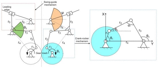
Figure 2.
Kinematic diagram of the flapping mechanism. The blue-dotted box is the crank-rocker mechanism and the red-dotted box is the swing-guide mechanism.
The degrees of freedom (DOF) of the mechanism were calculated. The mechanism is a planar, two-stage, four-bar mechanism, and the calculation formula of the DOF was adopted. There are five components on each side of the mechanism, including six rotating pairs and one moving pair. Therefore, its DOF is
—number of components; —revolute pair; —sliding pair.
Because of the symmetrical design of the mechanism on both sides, the mathematical model on one side was established. A coordinate system with the rotation center of the crank as the origin was established. First, the first-stage crank-rocker mechanism was analyzed, where is the crank length, is the connecting bar length, is the rocker length, and is the frame length. is the crank rotation angle, is the instantaneous position of the rocker, and is the transmission angle.
The vector equation of the four-bar mechanism was established:
This equation was decomposed into:
This equation was simplified, where was eliminated:
The following are further simplifications of :
After establishing the mathematical model of the first-stage crank-rocker mechanism, it was necessary to determine the conditions of each link length of the crank-rocker mechanism. The constraint conditions are size constraints, crank existence, minimum transmission angle conditions, and absence of quick-return characteristics, etc.
The equivalent crank length = 3.86 mm was taken as the initial condition for optimization. Moreover, the size of the mechanism should meet the condition that the crank is the shortest link, i.e.,
The minimum transmission angle condition was calculated. The transmission angles are complementary to ensure the transmission efficiency of the mechanism. The maximum pressure angle α1 should be 40–50°. The minimum transmission angle γ should not be less than 40°.
The lengths of , and were determined so that the mechanism had no quick-return characteristics. The two limit positions of the first-stage swing-rocker correspond to the limit positions of the second-stage swing-guide bar, so the flapping mechanical system has no quick-return characteristics. Moreover, it is required to meet the following requirements:
In the process of optimization, considering the relationship between the flapping angle of the wings and the output angle of the crank-rocker mechanism, we set the output angle of the crank-rocker mechanism as 80°, and take this as the objective function to optimize the rod length. The minimum value of the objective function is obtained when the constraint conditions are satisfied.
The nonlinear optimization function was utilized to optimize the above parameters, with and as the angles of the rocker at the extreme positions, respectively. The obtained data were integrated due to the factors of processing accuracy. The absence of quick-return characteristics (K = 1.0), the size limit, and the minimum transmission angle conditions meet the requirements. We optimize the link length through the ‘fmincon’ function in Matlab, and finally find the link length of the first-stage mechanism, which is r1 = 3.86, r2 = 10, r3 = 6, and r4 = 11. It is worth mentioning that the length of each rod can also be directly calculated by analytical methods. Moreover, the output swing angle of the first-stage mechanism is 80°. Finally, the length of the links in the first-stage mechanism were calculated. The calculation method of the link length in the second-stage mechanism is similar to that of the first-stage mechanism. Considering the installation position and assembly of the connectors, the flapping-angle amplitude was finally set to 160°, and the size parameters of the second-stage mechanism were calculated. Figure 3 shows the 3D model of the flapping wing system.
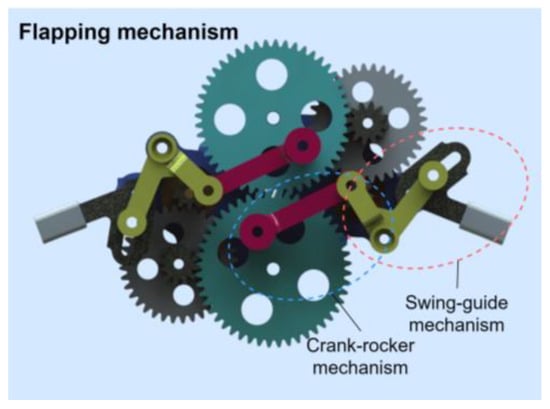
Figure 3.
Three-dimensional model of the flapping wing system.
2.3. Bionic Wings
In general, the wings of birds or insects are composed of feathers or membranes, while the veins are rigid bones. High-frequency flapping requires the wings to have sufficient strength to withstand the aerodynamic force from the normal direction of the wing surface. Meanwhile, the wings need to have the corresponding flexibility to realize passive deformation. This passive deformation can also realize a rotation circulation mechanism similar to that of insects, to improve the lift. The slack angle can effectively change the wing deformation during flapping, thereby improving the aerodynamic performance of the wings. After preliminary experiments and iterations, PET film was selected as the material for the wings, as it has excellent elastic deformation ability. The leading edge and veins are made of carbon fiber rods to ensure the rigidity of the wings. Through the research and preliminary study of the relevant literature [], the layout of the bionic wing in this paper is shown in Figure 4a.
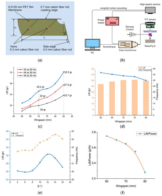
Figure 4.
Aerodynamic performance test of the wings. (a) Wing diagram. L—wingspan; C—mean chord length; β—slack angle, which affects the AoA of wings. (b) Diagram of aerodynamic force/torque test system. (c) Variation curves of span and mean lift at different frequencies. (d) Variation relationship between wingspan and lift at β = 12°. (e) Under the same driving power, the relationship between slack angle and lift force at different frequencies. The blue solid line represents the relationship curve between the lift and the slack angle, and the yellow dotted line represents the relationship curve between the flapping frequency and the slack angle. (f) Energy consumption and wingspan variation curve.
Referring to the research on wings [], experimental research was conducted for the optimal wingspan and slack angle. Considering the limitation of motor torque, an excessive wingspan will increase the moment of inertia of the wing and reduce the flapping efficiency of the vehicle. Meanwhile, the lift generated by the passive deformation of the wing is utilized. Through early experiments and research [,] on relevant papers, and according to the relationship between wing parameters and lift, preliminary experiments were conducted to determine the range of wing parameters. The chord of the wing was determined to be C = 25 mm, and the test range of the wingspan L was determined to be 60 mm~85 mm. The test range of the slack angle β was 4~16°. The optimal solution of the two parameters was obtained through experiments.
Figure 4b shows our aerodynamic/torque test system. In the experiment, in order to obtain intuitive measurement data, we utilized a DC power supply (Hyelec, Shanghai, China), which can display current and voltage data in real time, to drive the flapping mechanism. Meanwhile, the flapping frequency of the wings are measured by a stroboscope (Dexin, Suzhou, China). Install the flapping mechanism with wings on the 6-axis force sensor F6D45 (ME, Hennigsdorf, Germany), and obtain real-time lift data.
It can be seen from the experiment that the effect of the wingspan on lift is significant. As shown in Figure 4c, the lift of the vehicle increases with the increase in the wingspan at the same frequency. When the wingspan reaches 80 mm, the lift reaches the maximum value, but the output power of the vehicle also increases sharply, and the aerodynamic efficiency (the efficiency of the vehicle is usually defined by the lift/power ratio, which means the lift which can be generated per watt of power) is only 3.28 g/w in Figure 4f. The second experiment took the input power of the motor as a constant value to test the aerodynamic effect of each wing under the same power. As shown in Figure 4d, the aerodynamic force on the wings increases sharply with the increase in the wingspan, and the maximum frequency of the vehicle decreases continuously. The wingspan value of the optimal lift effect is between 70 mm and 75 mm, and the lift meets the lift demand of the vehicle. In the power consumption test, the lift–power ratio of the vehicle at 70 mm wingspan (lift/power = 3.65 g/w) is obviously better than that at 75 mm wingspan (lift/power = 3.55 g/w) in Figure 4f. Therefore, we chose the wingspan parameter of 70 mm for the wing design [].
The slack angle of the wings will affect their passive deformation and the deformation of the wings will affect lift and aerodynamic efficiency (lift–power ratio). When it is small, flexible deformation will not be obvious, the resistance in the horizontal direction of the wing surface is too large, and the lift in the vertical direction will be small. When it is large, it will produce large flexible deformation of the wings, the normal force of the wing surface will decrease, and the lift force in the vertical direction will also decrease. The value of β will reduce the aerodynamic efficiency, whether it is too large or too small. Therefore, it is very important to select the appropriate slack angle for the wing design. Under the same dimensional parameters and the same driving power, the lift of different slack angles under high-frequency flapping was tested, as shown in Figure 4e.
In addition to flapping motion, the wing needs to change the AoA through passive deformation, similar to the pitch angle of the wing. The deformation of the wings directly affects the aerodynamic force, and even unreasonable wing deformation will make the drag generated by the wing greater than the lift. In order to obtain accurate wing deformation, we utilized the flapping mechanism to conduct the wing flapping observation and experiment. Figure 5a shows that during the flapping motion, the wing is twisted along the wingspan, captured by a high-speed camera from the top view, in which the frame rate is 4000 and the flapping frequency is 20 Hz. With this twisted configuration, we found that the geometric AoA was 0.25, 0.5 and 0.75 times the wingspan in a flapping cycle, as shown in Figure 5b.
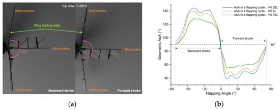
Figure 5.
(a) Composite images of the flapping wings captured by a high-speed camera from the top view of the FWMAV: (left) deformation of wings under backward stroke movement; (right) deformation of wings under forward stroke movement. (b) Evolution of the wing geometric AoA at 0.25, 0.5 and 0.75 times the wingspan in one flapping cycle.
A flapping cycle of a bionic FWMAV is divided into upstroke and downstroke. Since the wing-flapping plane in hovering flight is close to horizontal, this study divides a flapping cycle into forward stroke and backward stroke, as shown in Figure 5a, which is different from the previous classification method. From the geometric AoA curves in Figure 5b, it can be seen that the changes of the AoA in the two processes of forward stroke and backward stroke are close to the same, and the AoA does not remain unchanged. Compared with the evolution of the AoA at 0.25, 0.5 and 0.75 times the wingspan, the wing rotation angle at 0.25 L is only 27.9°, but it has become 39.4° at 0.75 L, which also means that the wing rotation angle increases with the wingspan. From this experiment, we can also compare the deformation and lift of the wings with different wing materials and veins.
2.4. Control Mode
The motion of FWMAVs is a complex nonlinear system. In attitude control, the control of each attitude should be decoupled to avoid the influence of different attitudes, resulting in a lack of stability of the vehicle. In terms of control methods, vehicles of the same size usually adopt a tailless flight control method, which is based on twisting the wing root or wing edge, changing the wing-flapping plane to generate attitude torque. In the actual flight process of birds and insects, their body’s center of gravity and tail wing also participate in attitude transformation, not just relying on wing-root control. The National University of Singapore and the Free University of Brussels have also conducted relevant research on tail wing design for hover-capable FWMAVs. This vehicle draws on the control method of birds’ tail wings to achieve attitude control. The two servos control the cross-tail wing to make the vehicle roll and pitch. The design of the tail wing refers to the design of our four-wing FWMAV’s test results and references [,,,,]. The tail wing has an initial wingspan of 140 mm and an initial chord of 70 mm. The control principle is as follows:
(1) Roll control, as shown in Figure 6b, controls the servo to make the cross-tail wing rotate anticlockwise or clockwise. In the downwash air flow of the flapping wing, the tail wing receives a force to form a rolling torque around the center of gravity. The tail wing rotates anticlockwise, and the torque generated by the force makes the vehicle roll anticlockwise.
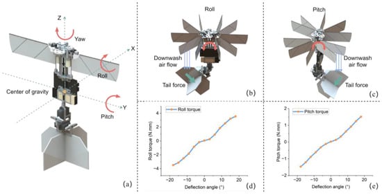
Figure 6.
Control mode of RoboFly.S. (a) Diagram of fuselage attitude change. (b) Roll motion due to force/torque change caused by tail wing deflection. (c) Pitch motion due to force/torque change caused by tail wing deflection. (d) Rolling torques and deflection angle of tail wing. (e) Pitching torques and deflection angle of tail wing.
(2) Pitch control, as shown in Figure 6c, controls the servo to make the cross-tail wing rotate anticlockwise or clockwise. In the downwash air flow of the flapping wing, the tail wing receives a force to form a pitching torque around the center of gravity. The tail wing rotates anticlockwise, and the torque generated by the force makes the vehicle pitch anticlockwise.
The parameters that affect the pitching/rolling torque are the distance between the tail wing and flapping wings, the chord length of the tail wing, the wingspan of the tail wing, the airfoil of the tail wing, and the deflection angle. This experiment mainly includes the tests and analyses of the deflection angle, rolling torque and pitching torque. A rectangle was selected for the tail wing airfoil, and the other parameters were taken as constants to test the relationship between the deflection angle and the pitching/rolling torques, as shown in Figure 6d,e. Keep the flapping frequency of the vehicle at 28 Hz and the lift is 27.2 g, which overcame self-weight. Due to assembly errors, the vehicle is not completely symmetrical in each direction. When the deflection angle is 0°, theoretically, each torque value should be 0 N·mm. However, there is a deviation between the pitching torque and rolling torque, and the rolling torque deviation is larger. When the deflection angle is within +3°, the torque changes little; meanwhile, when it is greater than 3°, the torque changes significantly. Theoretically, the deflection angle of the tail wing is +30°. In the test of the aerodynamic measurement system, the vehicle can generate a pitch torque of 1.51 N·mm and a roll torque of 3.85 N·mm, maintaining high lift, which is higher than that of vehicles of the same size.
2.5. Stability Analysis
The RoboFly.S designed in this study can achieve attitude stability by optimizing the structural layout and adjusting the aerodynamic center and tail wing. The dynamic model of the vehicle was simplified, as shown in Figure 7a. It is assumed that the fuselage mass is symmetrically distributed along the longitudinal section, and the center of gravity is located on the vertical line of the aerodynamic centers of the two wings. The dynamic model of the fuselage is divided into three modules. The first module is the equivalent aerodynamic center Wa.c, which generates lift Fa and drag fa; the second module is the center of gravity Xc.g, where the gravity G of the vehicle acts on this position; and the third module is the aerodynamic center Ta.c of the tail wing.
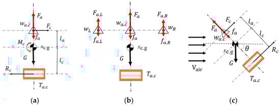
Figure 7.
Simplified flight stability analysis of RoboFly.S.
As the damper of the vehicle, the mechanical model of the tail wing can be understood as a velocity damper:
Here, is the viscous damping coefficient. During hovering flight, the flapping of the wings causes downwash air flow below the fuselage. As shown in Figure 7b, when the vehicle rotates counterclockwise around the center of mass, the tail wing passively generates aerodynamic drag perpendicular to the wing surface. Meanwhile, the tail wing is controlled by the servo to move in the opposite direction to the rotation of the fuselage. Due to the effect of the downwash air flow, the drag torque around the center of gravity is generated, thereby counteracting the rotation torque and keeping the attitude of the vehicle stable.
As shown in Figure 7c, when the vehicle flies forward with the pitch angle θ, if θ has a tendency to change the direction of the aerodynamic force generated by the tail wing surface will change, and torque will be generated by the vehicle to resist the change in θ. If the resistance torque and air rotation torque cancel each other out, the fuselage is in static equilibrium. This point is called the static equilibrium neutral point.
The size of \ is related to the aerodynamic performance of the vehicle wing surface, including the wing area and the fuselage’s angle of attack. When the vehicle is in equilibrium,
The above analysis is based on the premise that the center of gravity is arranged between the aerodynamic center and the center of the tail wing. When the center of gravity is far away from the tail wing, the influence of the impedance torque is gradually obvious, and thus the aerodynamic disturbance can be corrected and the stability of the vehicle can be maintained. When the center of gravity is above the equivalent aerodynamic center, the drag torque generated by the wings and tail wing is in the same direction as the disturbance torque, which makes the vehicle tilt further. Therefore, the static stability of the vehicle in the hovering state is related to the position of the center of gravity.
Next, we conducted a brief analysis of the attitude adjustment of the aircraft during hovering flight, as shown in Figure 8. When the aircraft undergoes a degree rotation in pitch attitude, the tail wing deflects by degrees, and the lift direction of the aircraft remains unchanged, resulting in a downwash airflow Fdown along the aircraft axis, that is:
—air resistance coefficient, —air density, —tail area, and —airflow velocity.
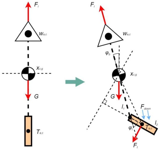
Figure 8.
Simplified aerodynamic analysis of pitch attitude adjustment.
By using the trigonometric function relationship, the aerodynamic force Ft acting on the tail wing and the adjusting moment Mp around the center of gravity of the fuselage generated by the tail wing deflection can be derived, thereby obtaining the dynamic relationship of the fuselage during pitch attitude adjustment:
l1—distance from the center of gravity of the aircraft to the rotation point of the tail wing, l2—tail chord length, Jp—moment of inertia, and —angular acceleration.
2.6. Analysis of Tail Wing
As mentioned above, we conducted aerodynamic experiments on the initial tail wing parameters, and the results are shown in Figure 6. When the tail wing is deflected at the same angle in both rolling and pitching directions, the difference between roll torque and pitch torque is significant. Under the same conditions, the rolling torque is much higher than the pitching torque. Therefore, it is necessary to adjust the tail wing parameters appropriately to obtain the required attitude torque []. Through the analysis of the experimental results, it is speculated that the reason for the different torques is the different flow velocities of the tail wing in the pitch and roll directions, which leads to significant differences. Therefore, we conducted measurements of the flow velocity around the tail wing using a UT363 anemometer (UNI-T, China). The vehicle was fixed and the anemometer was located 10 mm away from the leading edge of the tail wing. The flow velocities at 0.25R, 0.5R, 0.75R, and R of tail wingspan were tested. The results are shown in Table 2:
Table 2.
Flow velocity of tail wing.
For the design of hover-capable FWMAVs, the tail wing is mainly designed to maintain its attitude stability rather than providing lift. The purpose of conducting fluid analysis here is to test whether the tail wing’s span, chord length, and other aspects can meet the torque requirements of the aircraft during hovering-flight, providing a design reference range. However, the actual parameter determination needs to be improved and optimized through experiments. From Table 3, it can be seen that due to the flapping-wing motion mode, the distribution of downwash airflow velocity is uneven, and there is a significant difference in different directions, which has a significant impact on the torque generated by the tail wing. We analyzed the fluid changes around the tail wing, using 4.8 m/s and 2.6 m/s as the initial flow velocities for roll and pitch directions, respectively, at a span of 0.5R. Figure 9 shows the fluid simulation results. It can be seen that, with the increase in flow velocity and deflection angle, the changes in the tail wing flow field are also more severe. Table 3 shows the torques generated by the tail wing under the above six conditions.
Table 3.
Comparison between torque simulation values and experimental values.
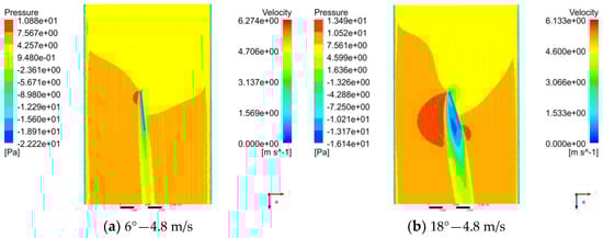
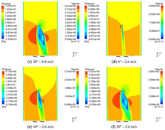
Figure 9.
Velocity and pressure distribution in the section of y = 0.5R. (a–c) In the roll state at 4.8 m/s of flow velocity, the flow velocity and pressure situation when the tail wing is deflected at 6°, 18°, and 30°. (d–f) In the pitch state at 2.6 m/s of flow velocity, the flow velocity and pressure situation when the tail wing is deflected at 6°, 18°, and 30°.
Through comparison, the simulation values of rolling torque under the same working condition are higher than the experimental values, while the experimental values of pitching torque are higher than the simulation values. The main reason is that the flow velocity distribution in the pitching state is more uniform, and the flow velocity difference at different extensions is smaller, while the flow velocity difference in the rolling state is large and the distribution is uneven. By comparing two sets of values, we increased the span length of the tail wing in the pitching direction, resulting in higher pitching torque. After modification, the maximum value of pitching torque was tested to be about 2.2 N·mm, and the maximum value of rolling torque was about 3.55 N·mm.
3. Flight Control System
3.1. Autopilot
The vehicle designed in this paper adopts an autopilot developed in our laboratory, as shown in Figure 10a. It weighs 2.02 g and integrates a microcontroller unit (MCU), communication module, inertial measurement unit (IMU), altitude sensor, drive module and other functional modules and it can transmit the flight status in real time.
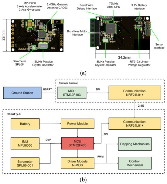
Figure 10.
(a) Autopilot of RoboFly.S. (b) Control system flow chart of Robofly.S.
The control system flow chart is shown in Figure 10b. The IMU integrated into the autopilot transmits the attitude information of the vehicle to the MCU after filtering. This study uses an MPU6050 as the attitude sensor and uses a second-order Butterworth filter with a cut-off frequency of 10 Hz to process accelerometer data. According to the cascade PID control algorithm used in this study, it is necessary to calculate the attitude angle of the aircraft, so complementary filtering is used to solve the attitude angle. The sampling frequency is set to 500 Hz, and the cut-off frequency of the gyroscope is 20 Hz. This cut-off frequency can obtain steady attitude data after debugging. The MCU outputs the control command to the drive modules according to the control algorithm. The drive modules control the two motors and the servos to adjust the flight state. The communication module communicates with the remote control in real time and transmits the attitude information of the vehicle to the remote control. Meanwhile, the remote control transmits the information to the ground station through the serial port. The ground station displays the flight status, and it can modify the control parameters.
3.2. Control Algorithm
The vehicle drives the motors and the servos to generate the aerodynamic force/torque to adjust the attitude angle of the fuselage. If the attitude angle is selected as the control target, the vehicle can quickly reach the desired value. However, the angular velocity is not zero, and it cannot stay in a stable state. The fuselage oscillates near the desired value of the attitude. Therefore, the commands of the PID controller need to be constantly updated to make the system stable. To make the attitude angle oscillate at a low speed and in a small range near the desired value, we introduce an angular velocity controller. The idea of the angular velocity controller is to reduce the steady state error of the attitude angle through integration, and when the attitude angle tends to be steady, the angular velocity tends to zero. The angle–angular velocity cascade PID controller designed in this paper is shown in Figure 11.
Figure 11.
Cascade PID controller.
In the cascade PID controller, the error between the filtered fuselage attitude angle and the desired attitude angle is utilized as the input of the angle PID controller of the outer loop. The angle loop performs anti-integral saturation limiting on the data. When the cumulative integration error is greater than the set threshold value, the threshold value is taken as the integral term multiplied by the integral proportional coefficient. The output of the angle loop is utilized as the input of the angular velocity PID controller of the internal loop, while the fuselage angular velocity is measured by the gyroscope, and the output of the angular velocity loop is also subjected to integral limiting processing to reduce the cumulative error. The discrete equation is
where , and represent the desired angle value, the angle and angular velocity measurement values of the kth sampling point, is the output of the outer loop and the target input of the inner loop, and represents the error between the desired angle and the attitude angle at the kth sampling point, indicates the error between the outer loop output and the output angular velocity of the gyroscope at the kth sampling point. The integral terms of the inner and outer loops of the cascade PID controller are all subjected to anti-integral saturation treatment:
where Limit is the cumulative integration of the angle error to [, ], uk is the kth output of the inner loop, and the amplitude limit is between the preset (min(u), max(u)), which is utilized to directly control the actuator and prevent the fuselage attitude from violent changes. The cascade PID control algorithm can ensure stable flight of the aircraft without relying on the flight dynamics model. Moreover, we also conducted tests on other control algorithms, such as the improved self-anti-interference control algorithm, but its flight performance is poor compared to the cascade PID algorithm and it is difficult to stabilize the flight. For the cascade PID algorithm, we have conducted more work on PID parameter adjustment and complementary filter settings.
4. Experiments and Flight Tests
This section mainly involves the regulation and flight test of the vehicle. The weight distribution of the vehicle is shown in Figure 12. The fuselage is mainly made of nylon material through 3D printing, and is supported by a carbon fiber rod, reducing the weight of the vehicle. By optimizing the design of the parts, the weight of the vehicle has been reduced from 26.2 g to 24.8 g. By carrying a large capacity battery, the endurance of the vehicle can also be improved.
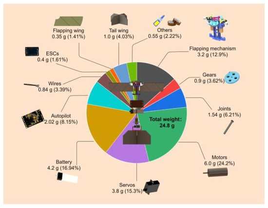
Figure 12.
The weight distribution of RoboFly.S.
4.1. Attitude Stability Test
To obtain the PID parameters of the attitude in the roll and pitch directions, we designed a rotary experimental platform for ground attitude control, which only has one rotational DOF, as shown in Figure 13. The center of the platform is a rotating rod, which is made of carbon fiber material to ensure rigidity and reduce the influence of its rotational inertia. The rotation rod is fixed to the vehicle, where the center of gravity of the vehicle is slightly higher than the rotation axis (rotating rod), so that the vehicle is in a free state, forming an inverted pendulum model. The PID parameters of the roll attitude and pitch attitude of the vehicle are controlled by the rotating platform.

Figure 13.
Attitude stability test. (a) Roll test platform. (b) Pitch test. (c) Pitch and roll angle error sampling under a steady state.
We tested the rolling attitude of the vehicle, reserved only one rolling DOF for the fuselage, and restricted the movement in other directions, as shown in Figure 13a. The attitude data were collected by the ground station with a sampling frequency of 100 Hz. We calibrated the gyroscope and accelerometer, utilized the remote control to control the vehicle, pushed the throttle to the position where lift overcomes the weight of the vehicle, and constantly modified the PID parameter values. The attitude curve of the vehicle at the torque where it reached a stable state is shown in Figure 13c. The attitude of the vehicle vibrated around 0°, and the maximum attitude error was controlled within 2.5°, which effectively demonstrates the stability of the vehicle in the rolling direction.
Similarly, when the pitch attitude was tested, only one pitch DOF was reserved to restrict the movement in other directions, as shown in Figure 13b. The test process was similar to the rolling test. The attitude curve of the vehicle when it reached a stable state is shown in Figure 13c. The maximum attitude error is only 0.9°, which effectively demonstrates the vehicle’s stability in the pitching direction.
4.2. Aerodynamic Test
First, the lift of the vehicle was measured. The experiment was mainly aimed at the relationship between the lift and frequency, thus contributing to the attitude control and maneuvering flight of RoboFly.S. The subsequent results will also help to revise the existing lift model. Figure 14a shows the relationship between the lift and flapping frequency. At 10 Hz, the vehicle showed a relatively obvious lift, and the lift grew rapidly at 20–28 Hz. The lift completely overcame the vehicle’s gravity at 28 Hz. However, the lift growth slowed down at 28–34 Hz. The vehicle’s flapping frequency reached 36 Hz, where a maximum lift of 34 g can be generated. When the input power is continuously increased, the lift of the vehicle can reach more than 34 g. However, when the flapping frequency reached 38 Hz or above, parts of the flapping mechanism were often damaged or fell off, meaning it could not operate stably for a long time. Moreover, the battery carried by the vehicle cannot provide high power. Therefore, the lift data at 38–40 Hz have no practical effect. Therefore, we generally controlled the flapping frequency below 36 Hz in the actual test and regulation experiments to ensure the reliability of the flapping system.

Figure 14.
Aerodynamic force/torque results of RoboFly.S. (a) Lift versus frequency curve. (b) Maximum pitching/rolling torques of the RoboFly.S in comparison to those of the similar-size tailless FWMAVs.
By comparing with other tailless FWMAVs in Figure 14b, the torque of the vehicle controlled by the tail wing is much higher than that of tailless vehicles, which greatly improves flight performance. Similarly, the control mode of the tail wing can also improve flight stability and robustness. Table 4 shows the comparison of parameters between RoboFly.S and hoverable bionic FWMAVs. Their size and weight are relatively close, and both achieve hovering flight. The difference is that the vehicles of DelFly Nimble and NUS-Roboticbird adopt a four-wing design. Through the above test, RoboFly.S shows high aerodynamic performance, relying on a smaller wingspan to produce higher lift, and utilizing a tail wing to produce higher torque, which provides a reliable design method for the development of FWMAVs.
Table 4.
Comparison of bio-inspired, hoverable FWMAVs.
4.3. Flight Test
We conducted flight experiments on the prototype RoboFly.S. As shown in the attitude stability test in the above sections, the vehicle could realize the rapid convergence of the roll and pitch attitude on the rotary experimental platform. Therefore, we conducted a free flight experiment. Figure 15 shows video screenshots of the indoor flight. In the flight test, the vehicle took off stably and responded quickly when there was a certain angle deviation, returned to a stable attitude, and realized a stable flight. However, due to the lack of yaw attitude control, it deflected in the yaw direction. Moreover, because the parameters tested on the attitude test platform were not accurate, the vehicle shook violently during attitude adjustment, the vehicle produced a circumferential displacement with a radius of about 1.8 m within 3.0 s and its flight time is only 8 s. This meant that the vehicle needed more accurate control parameters. After modifying PID parameters constantly, the stability of the vehicle was greatly improved. Figure 16 shows the flight effect of the vehicle after the precise experiment. Its stability was greatly improved, and the fuselage no longer shook violently, when the circumferential displacement was a radius of about 0.6 m within 4.0 s. The flight height of the vehicle can reach 3 m and its forward flight speed is 2.5 m/s, demonstrating its excellent indoor flight stabilization. However, due to the size of the test site, the vehicle often hit the boundary and fell. Therefore, we used the aerodynamic sensor to measure the lift of the vehicle and estimate its endurance. We used a fully charged 1S lithium battery to power the vehicle until the lift of the vehicle was less than its own weight. According to our test, the endurance of RoboFly.S can reach more than 2.5 min without interferences, depending on the battery capacity carried onboard.
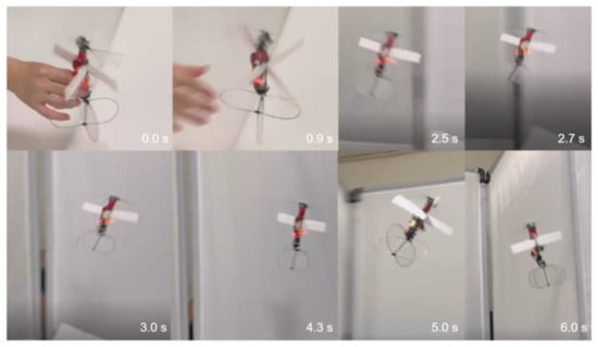
Figure 15.
Flight test of RoboFly.S before precise debugging.
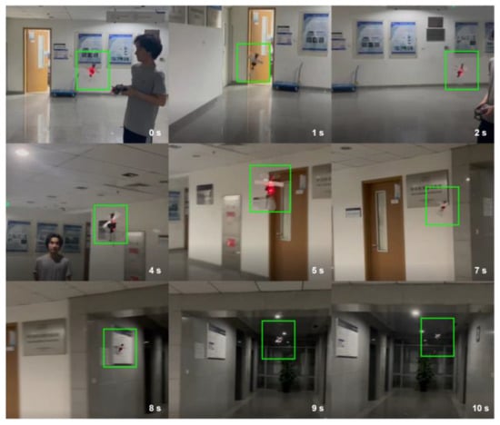
Figure 16.
Flight test of RoboFly.S after precise debugging.
5. Conclusions
This research presented the design and flight performance of a RoboFly.S vehicle with a cross-tail wing that utilizes a novel flapping mechanism. Through experimental optimization of wings and research into flight control systems, the vehicle can realize hovering flight and forward flight with load capacity. A novel flapping mechanism composed of a two-stage linkage mechanism has been devised and tested. The performance tests show that the lift of the vehicle is over 34 g with a wingspan of 16.5 cm. Moreover, the vehicle can carry a load of 3.4 g for flight, demonstrating the capability for applications. Optimization experiments have been conducted for the wing layout with the best aerodynamic force and lift–power ratio. A high-speed camera and 6-axis sensor are utilized to observe and measure the deformation of the wings and the aerodynamic data. The relationship between the wingspan, slack angle and lift, and lift–power ratio is obtained. The research is applied to the attitude control mechanism, utilizing the deflection of the cross-tail wing. The vehicle’s cross-tail wing is controlled by two servos, which decouple the attitude control and lift systems. This control mode reduces the interference of attitude control on lift, improving the flexibility and stability of the vehicle. With the test of the aerodynamic measurement system, the vehicle can generate a pitch torque of 2.2 N·mm and a roll torque of 3.55 N·mm, maintaining high lift, which is higher than that of vehicles of the same size. Flight tests show that the endurance of RoboFly.S can reach more than 2.5 min without interferences.
However, there are still some problems to be solved in the research process. First, the weight of the whole vehicle is 24.8 g, which is higher than other FWMAVs of the same size, which also reduces its lift–weight ratio and requires lightweight design. Second, while improving the stability of the vehicle, the tail wing will also face higher drag during maneuvering flight, which will reduce its flexibility. This requires in-depth study of the relationship between stability and mobility, and optimization of the airfoil and the parameters of the tail wing. Third, the design of the wings is still in the experimental stage and has not yet been matched by the theoretical design laws. The wing design of each vehicle is very different. There are many key parameters related: the average AoA, flapping angle, forward swept angle, aspect ratio and materials. The above problems still require further experiments and research. Future work will focus on the improvement of lift–weight ratio and further extension of the flight time. Moreover, vision sensors, flexible grippers, and other functional equipment are expected to be further installed on the vehicle. Above all, further research will focus on the improvement of the hovering stability, quick flight transition, and yaw attitude of the vehicle.
Author Contributions
Conceptualization, S.X. and H.D.; methodology, S.X.; software, Y.S.; validation, S.X., Y.S. and K.H.; formal analysis, S.X. and Y.S.; investigation, S.X. and K.H.; resources, H.D., D.R. and Y.W.; data curation, K.H.; writing—original draft preparation, S.X. and Y.S.; writing—review and editing, S.X. and H.D.; visualization, S.X. and Y.W.; supervision, D.R. and X.D.; project administration, X.D.; funding acquisition, Y.W., D.R. and H.D. All authors have read and agreed to the published version of the manuscript.
Funding
This research was funded in part by the National Science Foundation of China (No. 51975023).
Data Availability Statement
Data available on request from the authors.
Conflicts of Interest
The authors declare no conflict of interest.
References
- Gerdes, J.W.; Gupta, S.K.; Wilkerson, S.A. A review of bird-inspired flapping wing miniature air vehicle designs. J. Mech. Robot. 2012, 4, 021003. [Google Scholar] [CrossRef]
- Jones, A.R.; Babinsky, H. Reynolds Number Effects on Leading Edge Vortex Development on a Waving Wing. Exp. Fluids 2011, 51, 197–210. [Google Scholar] [CrossRef]
- Deng, H.; Xiao, S.; Huang, B.; Yang, L.; Xiang, X.; Ding, X. Design optimization and experimental study of a novel mechanism for a hoverable bionic flapping-wing micro air vehicle. Bioinspir. Biomim. 2020, 16, 026005. [Google Scholar] [CrossRef] [PubMed]
- Vejdani, H.R.; Boerma, D.B.; Swartz, S.M.; Breuer, K.S. The dynamics of hovering flight in hummingbirds, insects and bats with implications for aerial robotics. Bioinspir. Biomim. 2018, 14, 016003. [Google Scholar] [CrossRef] [PubMed]
- Keennon, M.; Klingebiel, K.; Won, H. Development of the nano hummingbird: A tailless flapping wing micro air vehicle. In Proceedings of the 50th AIAA Aerospace Sciences Meeting including the New Horizons Forum and Aerospace Exposition, Nashville, TN, USA, 9–12 January 2012; p. 588. [Google Scholar]
- Steltz, E.; Avadhanula, S.; Fearing, R.S. High lift force with 275 Hz wing beat in MFI. In Proceedings of the IEEE/RSJ International Conference on Intelligent Robots and Systems, San Diego, CA, USA, 29 October–2 November 2007; pp. 3993–3998. [Google Scholar]
- Graule, M.; Chirarattananon, P.; Fuller, S.; Jaferis, N.; Ma, K.; Spenko, M. Perching and takeoff of a robotic insect on overhangs using switchable electrostatic adhesion. Science 2016, 352, 978–982. [Google Scholar] [CrossRef]
- Chen, Y.; Wang, H.; Helbling, E.F.; Jaferis, N.T.; Zuferey, R.; Ong, A. A biologically inspired, flapping-wing, hybrid aerial-aquatic microrobot. Sci. Robot. 2017, 2, eaao5619. [Google Scholar] [CrossRef]
- Jaferis, N.T.; Helbling, E.F.; Karpelson, M.; Wood, R.J. Untethered flight of an insect-sized flapping-wing microscale aerial vehicle. Nature 2019, 570, 491–495. [Google Scholar] [CrossRef]
- Zou, Y.; Zhang, W.P.; Zhang, Z. Liftoff of an electromagnetically driven insect-inspired flapping-wing robot. IEEE Trans. Robot. 2016, 32, 1285–1289. [Google Scholar] [CrossRef]
- Lau, G.K.; Lim, H.T.; Teo, J.Y.; Chin, Y.W. Lightweight mechanical amplifers for rolled dielectric elastomer actuators and their integration with bio-inspired wing flappers. Smart Mater. Struct. 2014, 23, 025021. [Google Scholar] [CrossRef]
- Yan, X.J.; Qi, M.J.; Lin, L.W. Self-lifting artificial insect wings via electrostatic flapping actuators. In Proceedings of the IEEE International Conference on Micro Electro Mechanical Systems, Estoril, Portugal, 18–22 January 2015; pp. 22–25. [Google Scholar]
- De Clercq, K.M.; de Kat, R.; Remes, B.; van Oudheusden, B.W.; Bijl, H. Aerodynamic experiments on DelFly II: Unsteady lift enhancement. Int. J. Micro Air Veh. 2009, 1, 255–262. [Google Scholar] [CrossRef]
- Tijmons, S.; Karásek, M.; De Croon, G. Attitude control system for a lightweight flapping wing MAV. Bioinspir. Biomim. 2018, 13, 056004. [Google Scholar] [CrossRef] [PubMed]
- Karásek, M.; Muijres, F.T.; De Wagter, C.; Remes, B.D.; De Croon, G.C. A tailless aerial robotic flapper reveals that flies use torque coupling in rapid banked turns. Science 2018, 361, 1089–1094. [Google Scholar] [CrossRef] [PubMed]
- Karásek, M.; Nan, Y.; Romanescu, I.; Preumont, A. Pitch moment generation and measurement in a robotic hummingbird. Int. J. Micro Air Veh. 2013, 5, 299–309. [Google Scholar] [CrossRef]
- Karasek, M.; Hua, A.; Nan, Y.; Lalami, M.; Preumont, A. Pitch and roll control mechanism for a hovering flapping wing MAV. Int. J. Micro Air Veh. 2014, 6, 253–264. [Google Scholar] [CrossRef]
- Roshanbin, A.; Altartouri, H.; Karásek, M.; Preumont, A. COLIBRI: A hovering flapping twin-wing robot. Int. J. Micro Air Veh. 2017, 9, 270–282. [Google Scholar] [CrossRef]
- Roshanbin, A.; Abad, F.; Preumont, A. Kinematic and aerodynamic enhancement of a robotic hummingbird. AIAA J. 2019, 57, 4599–4607. [Google Scholar] [CrossRef]
- Preumont, A.; Wang, H.; Kang, S.; Wang, K.; Roshanbin, A. A note on the electromechanical design of a robotic hummingbird. Actuators 2021, 10, 52. [Google Scholar] [CrossRef]
- Phan, H.V.; Truong, Q.T.; Park, H.C. An experimental comparative study of the efficiency of twisted and flat flapping wings during hovering flight. Bioinspir. Biomim. 2017, 12, 036009. [Google Scholar] [CrossRef]
- Phan, H.V.; Kang, T.; Park, H.C. Design and stable flight of a 21 g insect-like tailless flapping wing micro air vehicle with angular rates feedback control. Bioinspir. Biomim. 2017, 12, 036006. [Google Scholar] [CrossRef]
- Phan, H.V.; Park, H.C. Mechanisms of collision recovery in flying beetles and flapping-wing robots. Science 2020, 370, 1214–1219. [Google Scholar] [CrossRef]
- Nguyen, Q.V.; Chan, W.L. Development and flight performance of a biologically-inspired tailless flapping-wing micro air vehicle with wing stroke plane modulation. Bioinspir. Biomim. 2018, 14, 016015. [Google Scholar] [CrossRef]
- Tu, Z.; Fei, F.; Zhang, J.; Deng, X. An at-scale tailless flapping-wing hummingbird robot. I. Design, optimization, and experimental validation. IEEE Trans. Robot. 2020, 36, 1511–1525. [Google Scholar] [CrossRef]
- Tu, Z.; Fei, F.; Deng, X. Untethered flight of an at-scale dual-motor hummingbird robot with bio-inspired decoupled wings. IEEE Robot. Autom. Lett. 2020, 5, 4194–4201. [Google Scholar] [CrossRef]
- Zhang, J.; Cheng, B.; Roll, J.A.; Deng, X.; Yao, B. Direct drive of flapping wings under resonance with instantaneous wing trajectory control. In Proceedings of the 2013 IEEE International Conference on Robotics and Automation, Karlsruhe, Germany, 6–10 May 2013; pp. 4029–4034. [Google Scholar]
- Xiao, S.; Deng, H.; Hu, K.; Zhang, S. Design and Control of Hoverable Bionic Flapping Wing Micro Air Vehicle. In Proceedings of the 2021 IEEE International Conference on Electrical Engineering and Mechatronics Technology, Qingdao, China, 2–4 July 2021; pp. 224–227. [Google Scholar]
- Nguyen, Q.V.; Chan, W.; Debiasi, M. Design, Fabrication, and Performance Test of a Hovering-Based Flapping-Wing Micro Air Vehicle Capable of Sustained and Controlled Flight. In Proceedings of the International Micro Air Vehicle Conference and Competition 2014, Delft, The Netherlands, 12–15 August 2014; pp. 18–25. [Google Scholar]
- Hines, L.; Campolo, D.; Sitti, M. Liftoff of a Motor-Driven, Flapping-Wing Microaerial Vehicle Capable of Resonance. IEEE Trans. Robot. 2014, 30, 220–232. [Google Scholar] [CrossRef]
- Guo, W. Mechanisms and Machine Theory; Science Press: Beijing, China, 2013. [Google Scholar]
- Nan, Y.; Karásek, M.; Lalami, M.E.; Preumont, A. Experimental optimization of wing shape for a hummingbird-like flapping wing micro air vehicle. Bioinspir. Biomim 2017, 12, 026010. [Google Scholar] [CrossRef]
- Phan, H.V.; Park, H.C. Design and evaluation of a deformable wing configuration for economical hovering flight of an insect-like tailless flying robot. Bioinspir. Biomim 2018, 13, 036009. [Google Scholar] [CrossRef] [PubMed]
- Li, H.; Nabawy, M.R.A. Wing Planform Effect on the Aerodynamics of Insect Wings. Insects 2022, 13, 459. [Google Scholar] [CrossRef]
- Phillips, N.; Knowles, K.; Bomphrey, R.J. The effect of aspect ratio on the leading-edge vortex over an insect-like flapping wing. Bioinspir. Biomim 2015, 10, 056020. [Google Scholar] [CrossRef] [PubMed]
- Nan, Y.; Chen, Y.; Mcglinchey, D.; Li, Y. Experimental Studies of Tail Shapes for Hummingbird-Like Flapping Wing Micro Air Vehicles. IEEE Access 2020, 8, 52622–52630. [Google Scholar] [CrossRef]
- Li, H.; Li, D.; Shen, T.; Bie, D.; Kan, Z. Numerical Analysis on the Aerodynamic Characteristics of an X-wing Flapping Vehicle with Various Tails. Aerospace 2022, 9, 440. [Google Scholar] [CrossRef]
- Armanini, S.; Caetano, J.; De Visser, V.; Pavel, M. Modelling wing wake and tail aerodynamics of a flapping-wing micro aerial vehicle. Int. J. Micro Air Veh. 2019, 11, 1756829319833674. [Google Scholar] [CrossRef]
- Jiao, Z.X.; Wang, L.; Zhao, L.F.; Jiang, W.Y. Hover flight control of X-shaped flapping wing aircraft considering wing–tail interactions. Aerosp. Sci. Technol 2021, 16, 106870. [Google Scholar] [CrossRef]
- Guzmán, M.M.; Páez, C.R.; Maldonado, F.J.; Zufferey, R.; Tormo-Barbero, J.; Acosta, J.; Ollero, A. Design and comparison of tails for bird-scale flapping-wing robots. In Proceedings of the 2021 IEEE/RSJ International Conference on Intelligent Robots and Systems (IROS), Prague, Czech Republic, 27 September–1 October 2021; pp. 6358–6365. [Google Scholar]
- Zerze, T.; Pandža, V.; Kasalo, M.; Zlatar, D. Discrete mechanics and optimal control optimization of flapping wing dynamics for Mars exploration. Aerosp. Sci. Technol 2020, 106, 106131. [Google Scholar]
Disclaimer/Publisher’s Note: The statements, opinions and data contained in all publications are solely those of the individual author(s) and contributor(s) and not of MDPI and/or the editor(s). MDPI and/or the editor(s) disclaim responsibility for any injury to people or property resulting from any ideas, methods, instructions or products referred to in the content. |
© 2023 by the authors. Licensee MDPI, Basel, Switzerland. This article is an open access article distributed under the terms and conditions of the Creative Commons Attribution (CC BY) license (https://creativecommons.org/licenses/by/4.0/).