Article

Effect of Multi-Joint Clearance Coupling on Shimmy of Nose Landing Gear

1
State Key Laboratory of Precision Manufacturing for Extreme Service Performance, Central South University, Changsha 410083, China
2
AVIC Landing-Gear Advanced Manufacturing Corp, Changsha 410200, China
*
Author to whom correspondence should be addressed.
Aerospace 2023, 10(11), 911; https://doi.org/10.3390/aerospace10110911
Submission received: 16 September 2023 / Revised: 16 October 2023 / Accepted: 20 October 2023 / Published: 25 October 2023
(This article belongs to the Special Issue Structural Dynamics and Control (2nd Edition))

Abstract

:
The existence of joint clearances in the nose landing gear (NLG) is inevitable and significantly affects shimmy. It was found that the interaction of each joint clearance is closely related to the analysis of shimmy stability. In this study, the shimmy model of NLG with three-dimensional joint clearance was established by using LMS VirtualLab Motion. Based on the method of multibody dynamics (MBD), the load transfer mechanism at the joints of the NLG was analyzed, and the oscillation characteristics with multiple joint clearances were investigated. The results indicate that the radial and axial contact force of the joint decreases from bottom to top, and the radial contact forces are relatively high at the end positions of the connection shafts, resulting in uneven wear. When the joint clearance reaches a certain value, periodic shimmy of the NLG will occur, and an increase in torsional damping can reduce the amplitude of the shimmy. Therefore, this study reveals the influence of multi-position joint clearance coupling on shimmy, and provides a valuable insight for the maintenance and design of landing gear joints.

1. Introduction

Landing gear achieves buffering, retracting, and turning functions through the assembly of several relative motion components. Inevitably, there are clearances between these relative motion components. Initially, the clearances are small, but with the occurrence of collisions and contact during relative motion, wear and tear will progressively increase the clearances. The excessive enlargement of these clearances will further disrupt the stability between the relative motion components, leading to a vicious cycle [1,2]. Additionally, the clearance between the relative motion components is not a simple planar clearance, but a complex spatial mechanism clearance.
During the takeoff and landing process, the nose landing gear (NLG) may experience a severe vibration phenomenon known as shimmy [3], which is characterized by the twisting of the wheel around its steering axis and lateral bending of the landing gear strut. There are various factors that can trigger NLG shimmy. Jiang et al. [4] investigated the impact of time-varying loads on Coulomb friction, revealing that time-varying loads can diminish the anti-shimmy effect of Coulomb friction. Thota [5] and Feng [6] employed bifurcation theory to study the influence of tire inflation pressure and torsional damping on shimmy. Furthermore, joint clearance is also an important influencing factor. For instance, concerning the modeling of spatial clearances in NLG shimmy, Grossman et al. [7] proposed the torsional clearance parameter θfp, which represents the difference between the inclination angle of the landing gear strut axis and the torsion angle of the dampers around the landing gear strut axis. On the other hand, Li [8] characterized the mechanism clearance using the difference between the rotational angles ψd relative to the center axis of the outer tube and ψc relative to the center axis of the turning sleeve. When this difference is smaller than the torsional clearance, there is no torque transmission between the damper and the ring.
As a hard non-linear factor, joint clearance makes shimmy analysis more challenging. The existing literature on the influence of clearance on shimmy mostly refers to a general parameter without specifying its exact location [9,10], and there has been little investigation into the coupling effects of clearances at specific locations on shimmy. With the advancement of computers and commercial software, research methods for NLG shimmy have also become more comprehensive and refined [11,12,13]. The modeling process can now consider more details, such as establishing a three-dimensional clearance model for joints, to accurately simulate the impact of joint clearances on shimmy. The innovation of this paper is to distinguish the joint clearances in different positions and establish a shimmy model with multiple joint clearances.
Landing gear is a key component of aircraft for achieving take-off and landing functions; in addition to safety, its comfort has also attracted much attention. In the field of aeroacoustics, Neri et al. [14] considered that the noise made by landing gear is one of the largest sources of aircraft noise. Guo et al. [15] studied the interaction between the gear cabin and the aerodynamic noise radiated by the landing gear, while Li et al. [16] revealed the temporal features and excitation rules of multiple tones in the NLG sound signal. Noise and vibration often interact with each other. Eret et al. [17] analyzed the impact of effective noise reduction solutions on shimmy stability. Suppressing or eliminating the phenomenon of landing gear shimmy is one of the design goals in landing gear systems. From a design perspective, the methods and measures primarily involve installing dampers and optimizing control strategies.
In most aircraft, the phenomenon of shimmy can be eliminated after installing dampers, and the damping coefficient of the damper is a critical parameter in its design, which can be determined using upper and lower critical anti-shimmy damping [18]. Regarding damper design, Boeing installs dampers at the top of the torque link and relies on the connection’s clearance to function [19]. On the other hand, UTAS dampers achieve multifunctionality in the torque link design by incorporating damping units, leading to weight reduction and ease of installation, but they encounter issues with unbalanced vibration responses [20]. Rahmani et al. [21,22,23] conducted simulation and comparative analysis on different damper design parameters’ effects on shimmy and performed structural optimization to enhance the anti-shimmy performance of a novel damper. In addition, in recent years, both domestic and international scholars have conducted research on the control of shimmy, aiming to suppress it by installing controllers and selecting appropriate control strategies. Research results [24,25,26,27] have demonstrated that adopting suitable control strategies can effectively suppress the occurrence of shimmy. However, such studies have remained limited to the theoretical domain and have not been implemented in practice. What deserves special attention is that the emergence of MR dampers [27,28] provides an effective controller for shimmy and accelerates the application of MR dampers in the field of shimmy control.
This paper takes a certain type of aircraft as the research subject and establishes a shimmy model with multiple joint clearances based on LMS Virtual.Lab Motion. An important contribution of this paper is to establish joint clearance models at different positions, study the impact characteristics of multi-joint clearance couplings on shimmy, and reveal the influence of joint clearances. The findings are of significant importance for the design of landing gear joint assembly dimensions and wear maintenance, providing valuable references. The remaining sections of the paper are arranged as follows: Section 2 introduces the NLG shimmy model; Section 3 analyzes the load transfer path; Section 4 studies the influence of multi-joint clearance coupling on shimmy stability; and Section 5 summarizes the whole paper.

2. Multibody Dynamics Model of the NLG with Joint Clearance

2.1. Dynamic Equation of Multibody System

In this paper, LMS Virtual.Lab Motion is used for modeling and solving, and the LaGrangian undetermined multiplier method is used to establish the dynamic equation of the multibody system, which has the maximum quantity but is highly sparse, so it is suitable to be solved efficiently by the method of coefficient matrix. The dynamic equation is
M Φ q T Φ q 0 q ¨ λ = F q , q ˙ , t γ
where Φ q T is the Jacobian matrix of the constraint equation, M is the mass matrix of multibody system, λ is the Lagrange multiplier, q is the composite vector of the generalized force of a multibody system, F q , q ˙ , t is the force of multibody system, and γ is the second derivative term in the acceleration formula.

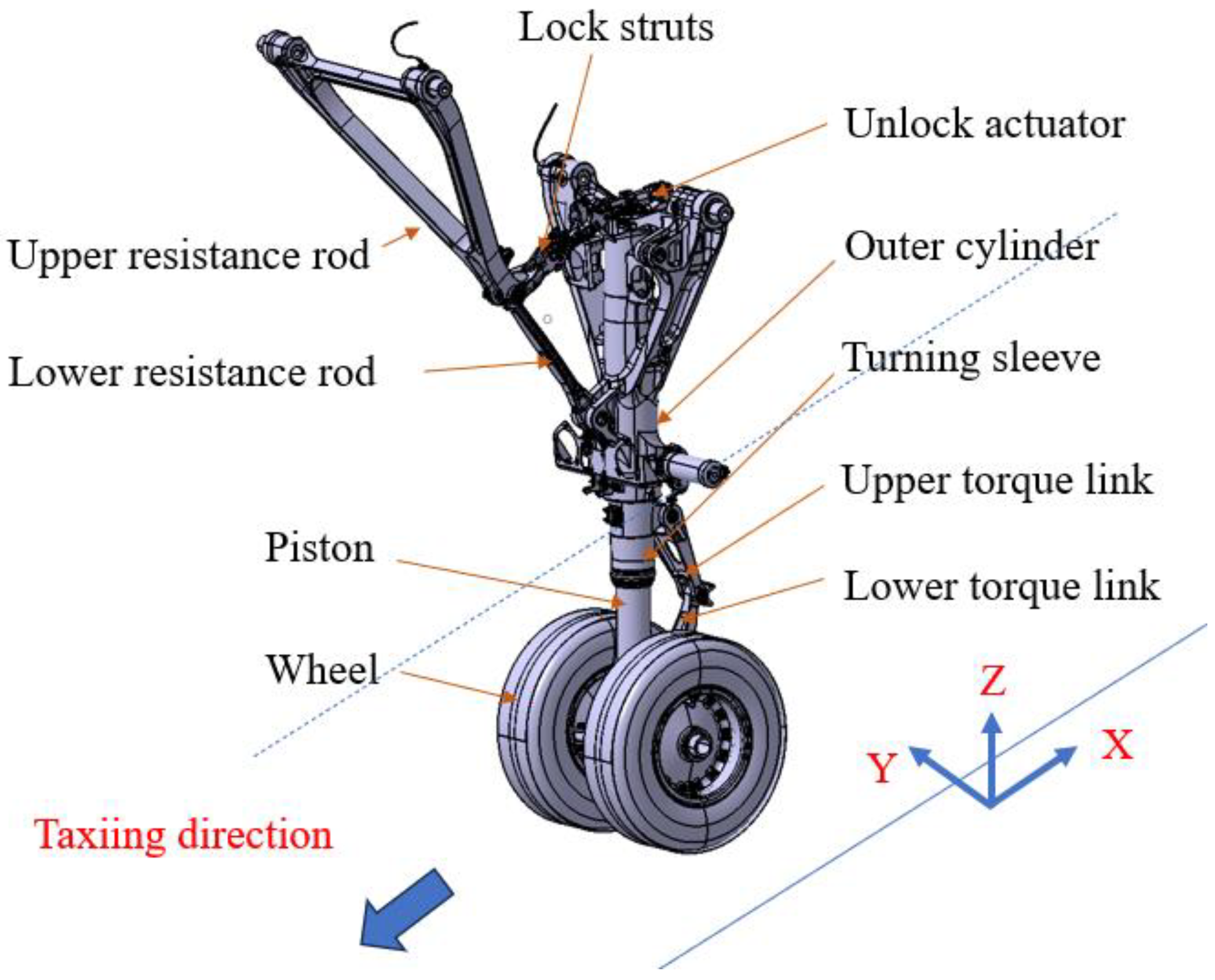
2.2. Simplified Model of NLG

A simplified 3D model of NLG was established in LMS Virtual.Lab Motion, as shown in Figure 1, including the outer cylinder of the strut, rotating sleeve, piston, wheel, upper and lower torque link, upper and lower resistance rod, lock structs, and unlock actuator. A motion pair is added to the component with relative motion, in which the motion relationship between the outer cylinder and the piston is a cylindrical pair, and the motion relationship between the upper lock brace and the unlock actuator is a fixed pair, and the rest is the rotating pair.

2.3. Load Applied to NLG

The loads applied to the NLG system mainly include air spring force, oil damping force, structural limiting force, anti-shimmy damping torque, and tire force, which are realized by different force elements. The relative position of each component is determined by calculating the vertical mechanical balance, and the vertical degree of freedom is provided for the upper and lower torque link. The data of the NLG shock absorber are shown in Table 1.
The air spring force Fa, oil damping force Fd, and structural limiting force F1 are specified as
F a = P a 0 V 0 V 0 A a S n P a t m A a
F d = d S ˙ 2 s i g n ( S ˙ )
F 1 = k s t r u t S 0 k s t r u t S S max S 0 0 S 430 S 430
where S ˙ and d designate the stroke rate of the shock absorber and oil damping coefficient, respectively. The maximum stroke of the shock absorber is 430 mm. According to the data provided by the author’s company, the oil damping coefficient d of the NLG shock absorber adopts a piecewise linear function, as depicted in Figure 2. Due to the difference in damping hole diameters between positive stroke and reverse stroke, there is a great difference in damping coefficient.
The shimmy damper is designed with a damping hole. The hydraulic oil flows through the damping hole to produce an anti-shimmy damping torque rotating around the axis of the pillar, and the direction is opposite to the swing direction of the front wheel, thus dissipating the mechanical energy of the shimmy. The anti-shimmy damping torque is specified as
M D = C d θ ˙
where Cd is the torsional damping of the strut and θ ˙ is the angular velocity of rotation of the strut.
In this paper, the NLG tire load adopts complex tire force elements in LMS Virtual.Lab Motion, which is based on tension string theory [29].

2.4. Analysis of Joint Connection Form

With the upper and lower torque links joint taken as an example, the schematic diagram of the connection is shown in Figure 3a. It is assembled using eight components: the upper torque link, lower torque link, connecting shaft, bushing, adjusting washer, spring washer, hexagon slotted nut, and cotter pin. Among these, there are 4 bushings connected with the upper torque link and 2 bushings connected with the lower torque link.
The radial clearance at the connection between the upper torque link and the lower torque link mainly occurs between the bushing and the connecting shaft, with a fit size of Φ26H8/f7, and the other two joints have the same fit tolerance. Based on the shaft–hole fit tolerance, the maximum radial assembly clearance at the upper and lower torque link connection is 0.037 mm, and the minimum radial assembly clearance is 0.01 mm. The axial clearance mainly arises from the position between the left and right adjusting washers and the bushing, with a maximum axial assembly clearance of 0.1 mm. The simplified diagram of the joint clearance is shown in Figure 3b, which identifies the location of the radial and axial clearance.

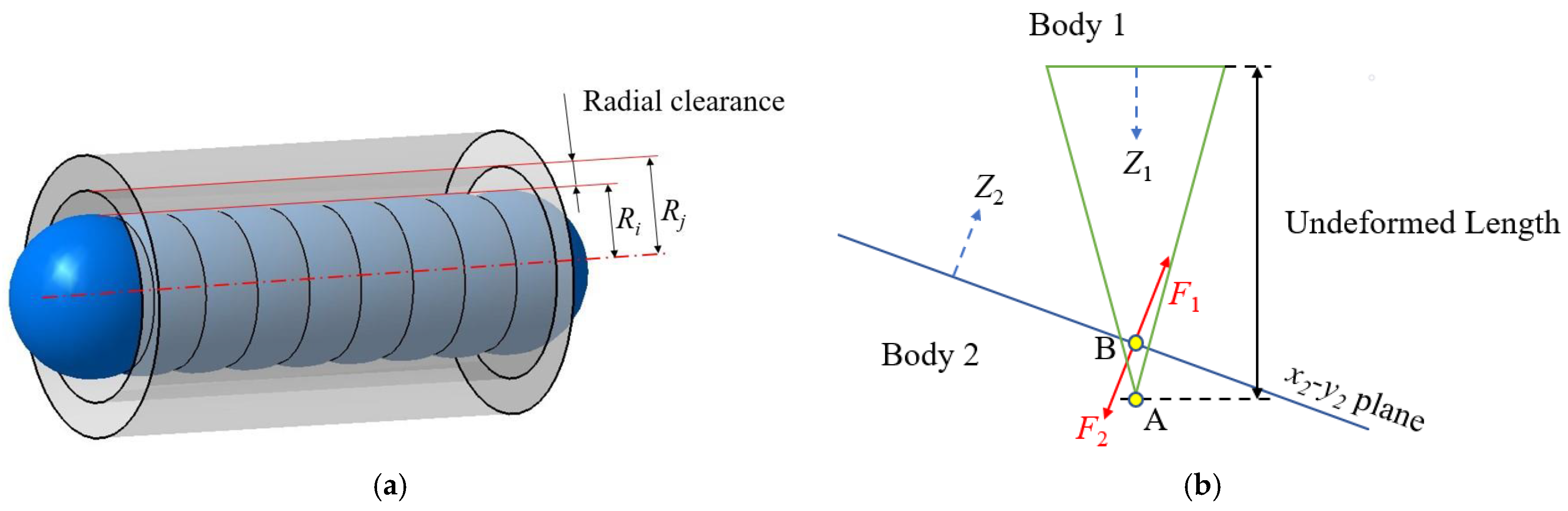
2.5. Establishment of Equivalent Model of Joint Clearance

In LMS Virtual.Lab Motion, the equivalent modeling of joint clearance is divided into two parts: the radial clearance model and axial clearance model, in which the spherical-extruded surface contact model is used in the joint radial clearance model. The shaft is represented by a number of spheres with a radius of Ri, and the shaft hole is simulated by an extrusion with a radius of Rj. The radial equivalent model can capture the contact and collision force between shaft and hole, and its theoretical model is based on the work of Young W. C. and Budynas R. G. [30]. As shown in Figure 4a, the unilateral clearance value Rj–Ri is used to represent the radial clearance, and the maximum radial clearance in this paper is 1 mm. The joint axial clearance model is simulated by two coordinate systems, and the bump stop force is used to represent the axial contact force, as shown in Figure 4b. The first axis system defines a point (marked A in the below figure) located on its Z axis at a distance of the attribute undeformed length. The bump stop material on the first part is idealized at this point. On the second body, a plane is defined by the x-y axes on that part. The material on the second part lies below this x2-y2 plane, while Z2 defines an outward normal to this material, and the coordinate system is defined at point B. F1 and F2 represent a pair of collision forces with equal values and opposite directions.
The detailed modeling process can be found in the previous work [31] of the current author.

2.6. Simulation Model Parameters

The shimmy model of the NLG based on LMS Virtual.Lab Motion is shown in Figure 5, and the main parameters of NLG shimmy simulation are shown in Table 2. In this paper, the take-off speed of the aircraft was 86 m/s. When the taxiing speed was stabilized at 50 m/s, an instantaneous exciting force of 5000 N was applied to the center of the left rotating shaft at the moment of 8 s, and the direction was the heading, in order to excite the shimmy of the NLG. If the system has strong anti-shimmy ability, it will converge gradually; otherwise, the shimmy will continue. The end time was 15 s, and the maximum solution step was set to 0.01 s, which was solved by the BDF method.

3. Load Transfer Analysis of NLG with Joint Clearances

In the context of relative motion, clearances inevitably exist between parts. In actual operational conditions, clearances are present at the joints of the NLG. Therefore, it is necessary to study the effects of multi-location clearance coupling on vibration. Among the various joints of the NLG, the wheel hub and axle are designed with an interference fit and do not introduce clearances. Hence, the following research focuses on three specific locations: the connection between the lower torque link and piston, the connection between the upper torque link and lower torque link, and the connection between the turning sleeve and upper torque link, which are defined as joints 1, 2 and 3, respectively. The schematic diagram of these three positions is shown in Figure 6a, and the connection structure of the three joints is simplified as shown in Figure 6b.
In this study, considering the presence of joint clearances at all three locations, radial and axial clearances of each connection were set to 0.1 mm. The taxiing speed was set to 50 m/s, and the damping for shimmy was 400 N·m·s/rad. A comparison was made between the yaw angle variation curves of the front wheel with clearances at individual locations and with clearances at multiple locations, as shown in Figure 7.
It can be observed from Figure 7 that when there is a clearance in all three positions, the initial yaw angle of the front wheel caused by the excitation is the largest, reaching 2.1 deg, indicating that the effect of the clearance on the initial torsion angle has a cumulative effect. Meanwhile, when clearances exist at all three locations, the yaw angle of the front wheel eventually settles into cyclic fluctuations of 0.16°, and the limit cycle oscillation occurs, while in other cases, it converges gradually. Additionally, the time-varying curve of the left axial clearance at the three locations is shown in Figure 8.
When all three locations have clearances, the left wheel axle undergoes external excitation, causing the piston to rotate counterclockwise, as depicted in Figure 8. The excitation force is transmitted on the right side of joint 1, then to the right side of joint 2, and finally to the left side of joint 3, and vice versa. In the subsequent shimmy period, the load is transmitted through the same-side path from joint 1 to joint 2, while it is transmitted through the opposite-side path to joint 3, and the axial clearance variation cycle is similar to the NLG shimmy period. Additionally, the radial contact force and axial contact force at the three locations are monitored to investigate the force distribution at each location. The time-varying curves of the radial contact force and axial contact force at these three locations are shown in Figure 9 and Figure 10.
It can be observed from Figure 9 that at the beginning of the excitation, the radial contact force of the three positions is the largest: joint 1 reaches 3780 N, joint 2 is 2800 N, and joint 3 is 2440 N. As the NLG gradually converges to a small-angle swing, the joint radial contact force gradually decreases and stabilizes at a fixed value in the order of 250 N of joint 1 > 110 N of joint 2 > 105 N of joint 3. Moreover, in the process of vibration, all the connecting shafts are subjected to force at the end, and there is almost no contact in the middle. Therefore, the radial load transfer is the largest at joint 1 and decreases gradually from the bottom to the top. If the system keeps shimmying for a long time, it is expected that serious wear will occur at the end of the connecting shaft, resulting in irregular wear on the shaft and bushing.
As can be seen from Figure 10, when subjected to external excitation, the right side of joint 1 first produces an axial contact force, the contact force value reaches 1780 N, and quickly transfers to the right side of joint 2; the contact force is 1440 N, and then to the left side of joint 3, the contact force is 1390 N. At this point, the excitation force is at its maximum. As the damper comes into effect, the force gradually decreases and stabilizes at a fixed value. The order of the axial contact force of the three stable positions is 95 N of joint 1 > 66 N of joint 2 > 52 N of joint 3. In the periodic shimmy stage, a comparative analysis of (a) and (b) shows that there is little difference between the left and right contact forces of the three positions. To sum up, the radial and axial contact forces of the joints are the largest at joint 1, and the contact forces decrease sequentially from the bottom up.

4. Shimmy Analysis of NLG with Multiple Joint Clearances

4.1. Influence of Taxiing Speed on Shimmy of NLG with Multiple Joint Clearances

Shimmy characteristics vary at different taxiing speeds. To further explore the impact of taxiing speed on the stability of shimmy in the NLG with multiple joint clearances, the radial clearances at three locations, namely the connection between the turning sleeve and the upper torque link, the connection between the upper and lower torque links, and the connection between the lower torque link and the piston, were fixed at 0.1 mm, and the axial clearances were set to 0.1 mm. The taxiing speed was adjusted to 10, 30, 50, 70, and 90 m/s. The time-varying curves of the front wheel yaw angle were obtained and are shown in Figure 11.
From Figure 11, it can be observed that compared to the ideal case of neglecting clearances, increasing the taxiing speed in situations where all three locations have 0.1 mm radial and 0.1 mm axial clearances will reduce the initial yaw angle magnitude generated due to excitation and the time required for its development. However, the key difference lies in the behavior of the front wheel yaw angle: in the former case, the front wheel yaw angle converges to around 0° after two cycles, while in the latter case, the front wheel yaw angle remains in a periodic fluctuating state around a fixed yaw angle. Moreover, at taxiing speeds between 10 m/s and 30 m/s, the amplitude of the front wheel yaw angle slightly increases for the situation with multiple joint clearances, from 0.168 deg to 0.170 deg, and between 30 m/s and 90 m/s, the amplitude exhibits a decreasing trend, with the lowest value being 0.155 deg. Furthermore, Fourier transformation was performed on the time-domain curves of the front wheel yaw angle for the cases with multiple joint clearances at different taxiing speeds, obtaining the frequency characteristics shown in Figure 12.
It can be observed from Figure 12 that the shimmy frequency increases as the taxiing speed increases from 10 m/s to 90 m/s, but it reaches a maximum of only 6.3 Hz, indicating that the oscillation remains in the low-frequency range. The curve fitting of the point graph is carried out, and the degree of fit R2 is 0.99666.

4.2. Impact of Multiple Joint Wear on the Shimmy of NLG

Considering the previous analysis, the shimmy damper damping coefficient was set to the design value of 400 N·m·s/rad, and the taxiing speed was set to 30 m/s. Different values of radial and axial clearances were selected for the three joints to simulate different degrees of wear, and the time-varying curves of the front wheel yaw angle were analyzed. The combinations of axial and radial clearances for the three joints are presented in Table 3.
Figure 13a shows the time variation curve of the front wheel swing angle corresponding to the serial numbers 1, 2, and 3, from which it can be seen that the increase of the radial clearance increases the initial front wheel swing angle generated by the excitation without changing the time required to produce it. When the radial clearance increases by 0.01 mm, the front wheel swing angle finally converges, but when the radial clearance increases by 0.02 mm, the swing angle is in 0.117 deg periodic torsion. Figure 13b shows the time variation curve of the front wheel swing angle corresponding to the serial numbers 1, 4, and 5. As can be seen from the figure, the increase in the axial clearance will also increase the initial front wheel swing angle generated by the excitation, but does not change the time required to produce it. When the axial clearance increases by 0.01 mm or 0.02 mm, the front wheel swing angle can still converge gradually. Figure 13c shows the time variation curve of the front wheel swing angle corresponding to the serial numbers 1 and 6. When the radial clearance and axial clearance increase by 0.01 mm at the same time, the front wheel swing angle is in a periodic torsion of 0.107 deg.
In summary, on the basis of the maximum assembly clearance, when the radial wear of each joint reaches 0.02 mm or the radial and axial wear reaches 0.01 mm, limit cycle oscillation may occur in the NLG. Therefore, during the maintenance of the NLG, the radial wear and axial wear of the joint connectors are avoided. However, the wear amount corresponding to the above research conclusions is an ideal hypothetical value, and the conclusions only reveal the general law of the effect of clearance on shimmy. More data are needed to support the actual maintenance.

4.3. Influence of Shimmy Damper Damping on Shimmy of NLG with Multiple Clearances

During the service life of the NLG, adjusting the damping of the shimmy damper has become an important measure to prevent oscillations. To further investigate the influence of the shimmy damper damping on the stability of the shimmy with multiple clearances, the shimmy damper damping was adjusted to 0.5 times, 1.5 times, and 2 times the design value, corresponding to 200, 400, 600, and 800 N·m·s/rad, respectively. The time-varying curves of the front wheel yaw angle under the conditions of multiple clearances and neglecting clearances are shown in Figure 14a,b, respectively.
It can be seen from Figure 14 that for the NLG model with clearance, the yaw angle of periodic oscillation decreases slightly as the damping force of the shimmy damper increases from 200 N·m·s/rad to 600 N·m·s/rad. In order to counteract the influence of periodic oscillation, it is necessary to increase the damping coefficient of the yaw damper to 800 N·m·s/rad. For the working condition without clearance, the shimmy can converge. In other words, the damper damping can restrain the limit cycle oscillation caused by the joint clearance. In the maintenance stage of the NLG, the damping value can be changed by replacing the damping hole of the damper. If the joint is worn, in addition to replacing the worn parts, the hidden danger caused by the joint clearance to the shimmy can be eliminated by increasing the damping value. However, according to the author’s previous research [18], excessive damping of the shimmy damper leads to the unstable direction of the aircraft, which puts forward higher requirements for the design of the shimmy damper. At the same time, it will also limit the promotion of the method of reducing clearance interference by increasing damping.

5. Conclusions

In this study, a multi-body dynamics model of the NLG with multiple joint clearances was established using LMS Virtual.Lab 13.6 software. The analysis focused on the load transmission and oscillation characteristics of the landing gear with clearances. The following conclusions were drawn from the investigation:
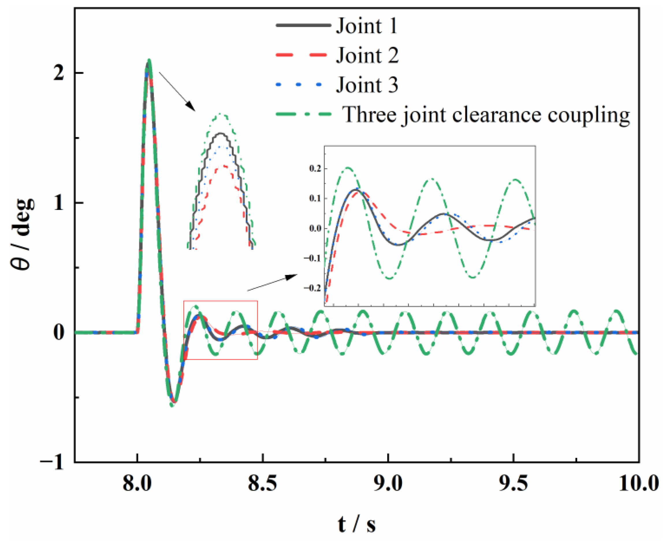
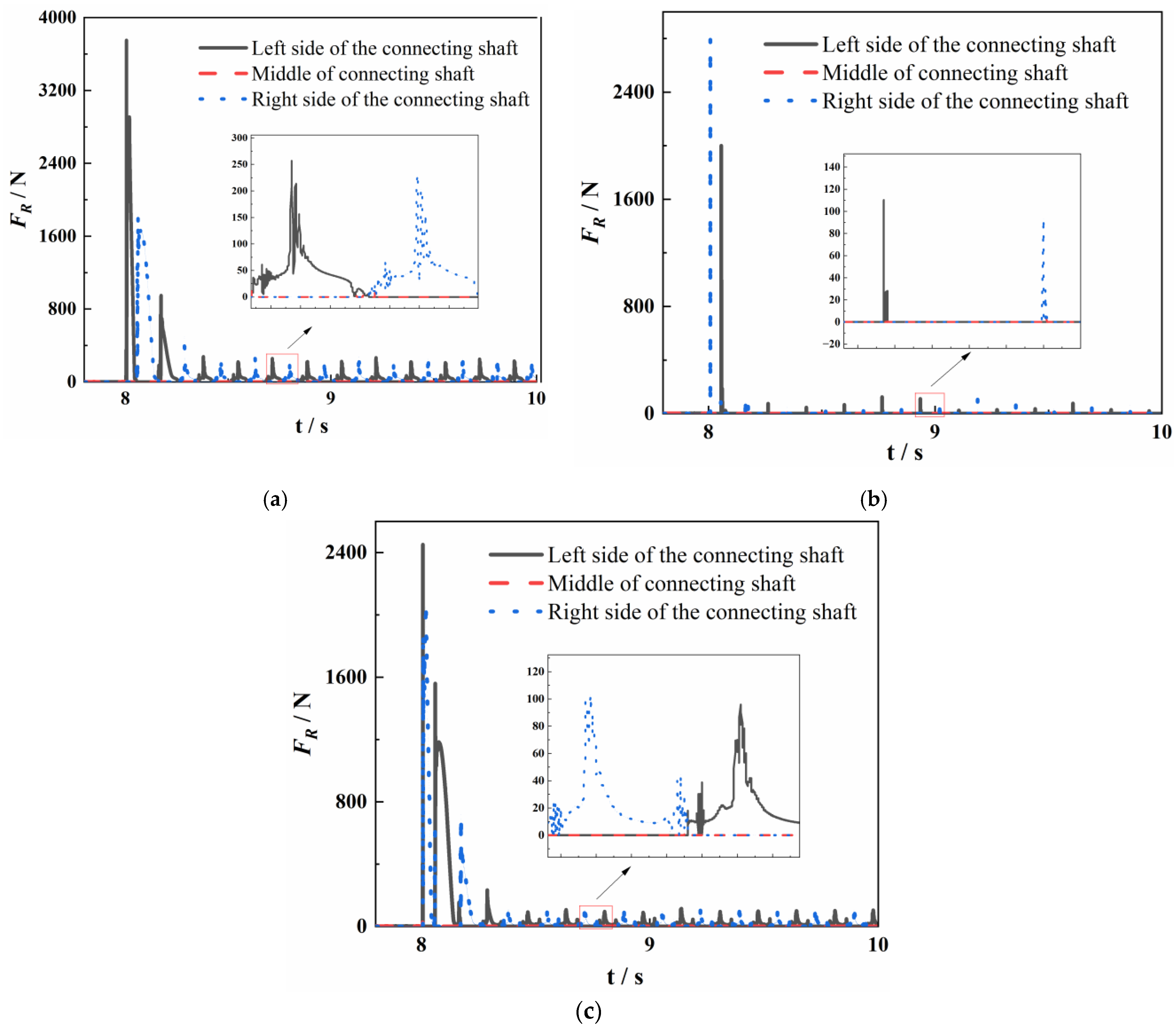
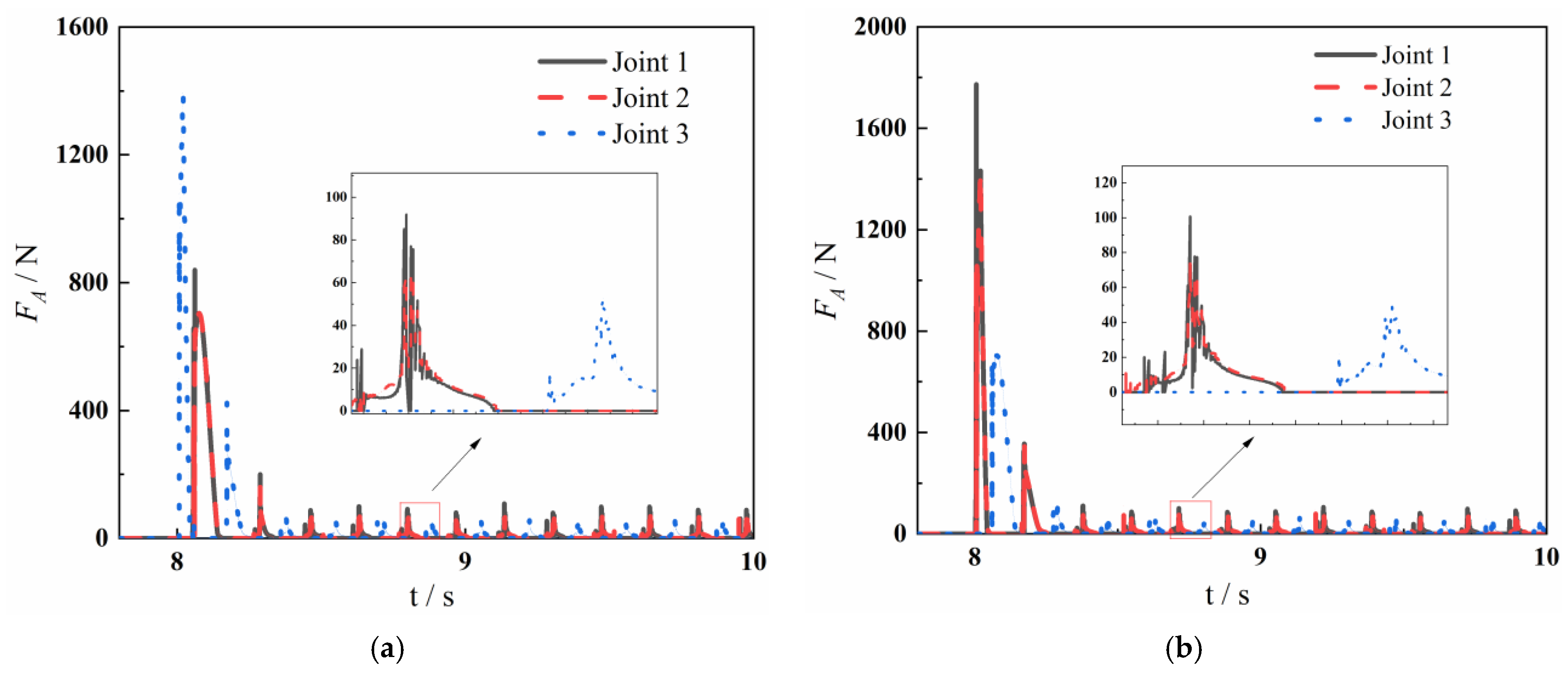
  • Multiple joint clearances increase the occurrences of axial contact collisions and result in increased wear. During the occurrence of oscillations, the axial contact force transmission at the three joint positions follows a same-side path at joint 1 and joint 2, while it follows an opposite-side path at joint 3. The radial and axial contact force of the joint is the largest at joint 1 and the smallest at joint 3, and the radial contact forces are higher at the ends of the connecting shafts, leading to uneven wear of the shafts and bushings.
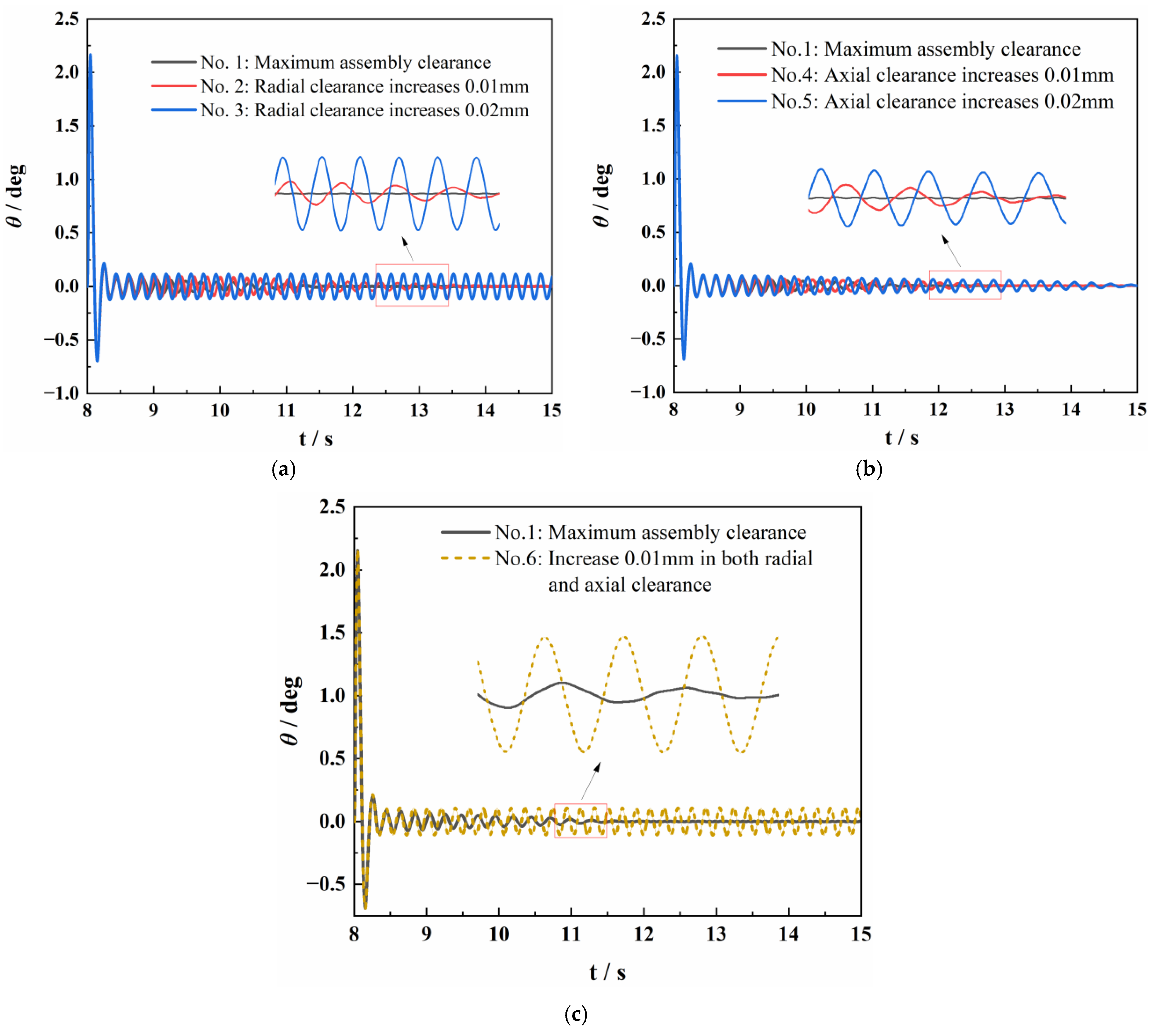
  • Joint clearances cause periodic oscillations of the NLG’s front wheel. With increasing taxiing speed, the amplitude of periodic oscillations shows an increasing trend within the range of 10 to 30 m/s, while it shows a decreasing trend within the range of 30 to 90 m/s. When the damping coefficient is 400 N·m·s/rad, an increase of 0.02 mm in radial clearance wear would lead to a periodic oscillation of 0.117°, or a simultaneous increase of 0.01 mm in axial and radial clearances would result in a periodic oscillation of 0.107°. These findings provide valuable insights for the maintenance of the NLG. However, more data support is needed for the specific implementation.
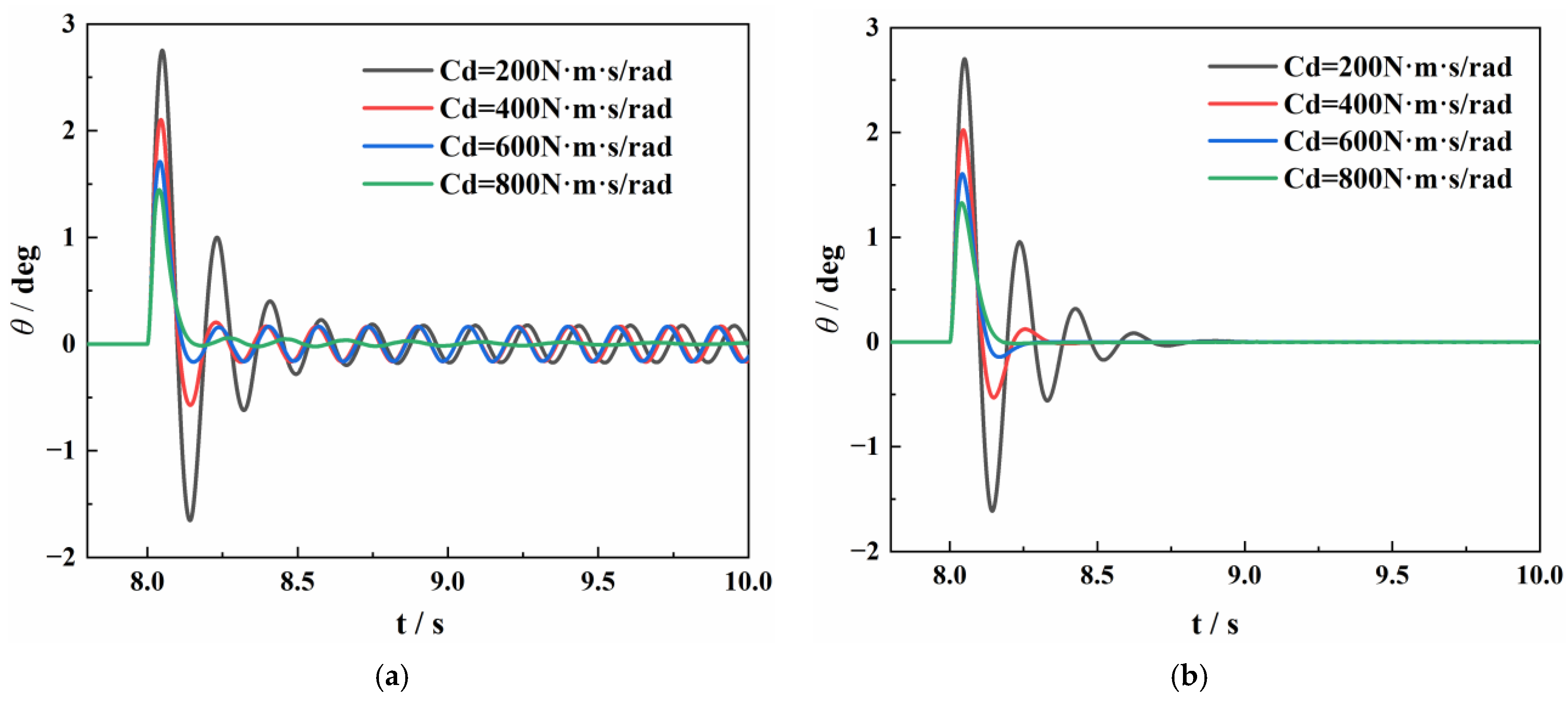
  • Increasing the damping coefficient reduces the amplitude of front wheel periodic oscillations caused by clearances, and when the value is twice the design value, the front wheel angle eventually converges to 0°. Therefore, it is possible to reduce the interference from clearances by increasing the damping coefficient of the damper, but too large of a damping value will lead to the hidden danger of aircraft direction instability. Future research should focus on optimizing the shimmy damper design and exploring other damping mechanisms to improve the stability of the NLG during operation.

Author Contributions

Conceptualization: G.F. and Y.J.; Investigation: G.F.; Methodology: G.F., Y.J. and B.J.; Software: G.F.; Writing—original draft: G.F. and Y.J.; Writing—review and editing, B.J. and Y.J.; Project administration: B.J.; Supervision: G.F. and Y.J. All authors have read and agreed to the published version of the manuscript.

Funding

This work was funded by the Civil Aircraft Special Project of the MIIT, grant number JZ025-XY-003.

Data Availability Statement

Not applicable.

Acknowledgments

The authors gratefully acknowledge the research grant provided by the Civil Aircraft Special Project of the MIIT (Grant No. JZ025-XY-003) in support of this work.

Conflicts of Interest

The authors declare no conflict of interest.

References

  1. Yin, Y.; Xu, K.; Nie, H.; Wei, X.; Wang, H. Dynamics Analysis of Spatial Landing-Gear Mechanism with Hinge Clearance and Axis Deviation. J. Aircr. 2021, 58, 30–42. [Google Scholar] [CrossRef]
  2. Marques, F.; Isaac, F.; Dourado, N.; Flores, P. An Enhanced Formulation to Model Spatial Revolute Joints with Radial and Axial Clearances. Mech. Mach. Theory 2017, 116, 123–144. [Google Scholar] [CrossRef]
  3. William, J. Moreland The Story of Shimy. J. Aeronaut. Sci. 1954, 21, 793–808. [Google Scholar]
  4. Jiang, Y.; Feng, G.; Tang, H.; Zhang, J.; Jiang, B. Effect of Coulomb Friction on Shimmy of Nose Landing Gear under Time-Varying Load. Tribol. Int. 2023, 188, 108828. [Google Scholar] [CrossRef]
  5. Thota, P.; Krauskopf, B.; Lowenberg, M. Nonlinear Analysis of the Influence of Tyre Inflation Pressure on Nose Landing Gear Shimmy. AIAA Model. Simul. Technol. Conf. 2009. [Google Scholar] [CrossRef]
  6. Feng, F.; Nie, H.; Zhang, M.; Peng, Y. Effect of Torsional Damping on Aircraft Nose Landing-Gear Shimmy. J. Aircr. 2015, 52, 561–568. [Google Scholar] [CrossRef]
  7. Grossman, D.T. F-15 Nose Landing Gear Shimmy, Taxi Test and Correlative Analyses. SAE Trans. 1980, 89, 3781–3791. [Google Scholar] [CrossRef]
  8. Li, G. Modelling and Analysis of a Dual-Wheel Nosegear: Shimmy Instability and Impact Motions; Aerospace Atlantic Conference & Exposition; SAE: Warrendale, PA, USA, 1993. [Google Scholar]
  9. Rahmani, M.; Behdinan, K. Studying the Effect of Freeplay on Nose Landing Gear Shimmy Using a Fully Nonlinear Model. Proc. ASME Des. Eng. Tech. Conf. 2018, 6, 1–11. [Google Scholar] [CrossRef]
  10. Howcroft, C.; Lowenberg, M.; Neild, S.; Krauskopf, B. Effects of Freeplay on Dynamic Stability of an Aircraft Main Landing Gear. J. Aircr. 2013, 50, 1908–1922. [Google Scholar] [CrossRef]
  11. Somieski, G. Shimmy Analysis of a Simple Aircraft Nose Landing Gear Model Using Different Mathematical Methods. Aerosp. Sci. Technol. 1997, 1, 545–555. [Google Scholar] [CrossRef]
  12. Thota, P.; Krauskopf, B.; Lowenberg, M. Multi-Parameter Bifurcation Study of Shimmy Oscillations in a Dual-Wheel Aircraft Nose Landing Gear. Nonlinear Dyn. 2012, 70, 1675–1688. [Google Scholar] [CrossRef]
  13. Rahmani, M.; Behdinan, K. Investigation on the Effect of Coulomb Friction on Nose Landing Gear Shimmy. JVC/J. Vib. Control 2019, 25, 255–272. [Google Scholar] [CrossRef]
  14. Neri, E.; Kennedy, J.; Bennett, G.J.; Reilly, C.O.; Dahan, J.; Esposito, M.; Di Giulio, M.; Bruno, M.; Amoroso, F. Characterization of low noise technologies applied to a full scale fuselage mounted nose landing gear. In Proceedings of the 44th International Congress and Exposition on Noise Control Engineering, San Francisco, CA, USA, 9–12 August 2015; pp. 1–10. [Google Scholar]
  15. Guo, Z.; Liu, P.; Zhang, J.; Guo, H. Numerical Simulation of Aeroacoustic Noise from Landing Gear and Rectangular Cavity. Proc. Inst. Mech. Eng. Part G J. Aerosp. Eng. 2020, 234, 1259–1271. [Google Scholar] [CrossRef]
  16. Li, L.; Liu, P.; Xing, Y.; Guo, H. Wavelet Analysis of Multiple Tonal Phenomena Generated from a Simplified Nose Landing Gear and a Ring Cavity. J. Sound Vib. 2020, 464, 114980. [Google Scholar] [CrossRef]
  17. Eret, P.; Kennedy, J.; Bennett, G.J. Effect of Noise Reducing Components on Nose Landing Gear Stability for a Mid-Size Aircraft Coupled with Vortex Shedding and Freeplay. J. Sound Vib. 2015, 354, 91–103. [Google Scholar] [CrossRef]
  18. Jiang, Y.; Feng, G.; Liu, P.; Yuan, L.; Ding, J.; Jiang, B. Influence of Nose Landing Gear Torsional Damping on the Stability of Aircraft Taxiing Direction. Aerospace 2022, 9, 729. [Google Scholar] [CrossRef]
  19. Boehringer, W.E. Torque Linkage Damper. US Patent 8,3,499,621 A, 10 March 1970. [Google Scholar]
  20. Luce, W.E. Torque Link with Shimmy Damper. US Patent 8,292,218 B2, 23 October 2012. [Google Scholar]
  21. Rahmani, M.; Behdinan, K. Parametric Study of a Novel Nose Landing Gear Shimmy Damper Concept. J. Sound Vib. 2019, 457, 299–313. [Google Scholar] [CrossRef]
  22. Rahmani, M.; Behdinan, K. On the Effectiveness of Shimmy Dampers in Stabilizing Nose Landing Gears. Aerosp. Sci. Technol. 2019, 91, 272–286. [Google Scholar] [CrossRef]
  23. Rahmani, M.; Behdinan, K. Structural Design and Optimization of a Novel Shimmy Damper for Nose Landing Gears. Struct. Multidiscip. Optim. 2020, 62, 2783–2803. [Google Scholar] [CrossRef]
  24. Laporte, D.J.; Lopes, V.; Bueno, D.D. An Approach to Reduce Vibration and Avoid Shimmy on Landing Gears Based on an Adapted Eigenstructure Assignment Theory. Meccanica 2020, 55, 7–17. [Google Scholar] [CrossRef]
  25. Orlando, C.; Alaimo, A. A Robust Active Control System for Shimmy Damping in the Presence of Free Play and Uncertainties. Mech. Syst. Signal Process. 2017, 84, 551–569. [Google Scholar] [CrossRef]
  26. Li, Y.; Howcroft, C.; Neild, S.A.; Jiang, J.Z. Using Continuation Analysis to Identify Shimmy-Suppression Devices for an Aircraft Main Landing Gear. J. Sound Vib. 2017, 408, 234–251. [Google Scholar] [CrossRef]
  27. Tourajizadeh, H.; Zare, S. Robust and Optimal Control of Shimmy Vibration in Aircraft Nose Landing Gear. Aerosp. Sci. Technol. 2016, 50, 1–14. [Google Scholar] [CrossRef]
  28. Zhu, S.X.; Li, J.; Wang, B. Research on Fuzzy Control of MR (Magneto-Rheological) Damper for Landing Gear Based on FuzzyTECH. Appl. Mech. Mater. 2015, 779, 212–219. [Google Scholar]
  29. Smiley, R.F. Correlation, Evaluation, and Extension of Linearized Theories for Tire Motion and Wheel Shimmy. NACA Tech. Note 1956, 3632, 1–145. [Google Scholar]
  30. Young, W.C.; Budynas, R.; Sadegh, A. Roark’s Formulas for Stress and Strain; McGraw-Hill: New York, NY, USA, 2011; pp. 596–597. ISBN 9781260453768. [Google Scholar]
  31. Jiang, Y.; Feng, G.; Liu, P.; Yuan, L.; Ding, J.; Jiang, B. Evaluation of Joint Clearance Effects on the Shimmy of Nose Landing Gear. Aerospace 2023, 10, 772. [Google Scholar] [CrossRef]
Figure 1. Assembly model of the NLG.
Aerospace 10 00911 g001
Figure 2. Oil damping coefficient of positive and reverse stroke of the NLG shock absorber.
Aerospace 10 00911 g002
Figure 3. Schematic diagram of the connection between the upper and lower torque links. (a) Joint assembly drawing; (b) joint clearance identification.
Aerospace 10 00911 g003
Figure 4. Joint clearance equivalent model. (a) Radial clearance; (b) axial clearance.
Aerospace 10 00911 g004
Figure 5. Shimmy simulation model of NLG based on LMS Virtual.Lab Motion.
Aerospace 10 00911 g005
Figure 6. Schematic diagram of the NLG with multiple joint clearances. (a) General picture of NLG; (b) simplified diagram of joint structure in 3 positions.
Aerospace 10 00911 g006
Figure 7. Time-varying curves of front wheel yaw angles for different location combinations.
Aerospace 10 00911 g007
Figure 8. Time variation curve of left axial clearance of joint in different positions.
Aerospace 10 00911 g008
Figure 9. Time-varying curves of radial contact forces for different location combinations. (a) Joint 1; (b) joint 2; (c) joint 3.
Aerospace 10 00911 g009
Figure 10. Time-varying curves of axial contact forces for different location combinations. (a) Left-side axial contact force; (b) right-side axial contact force.
Aerospace 10 00911 g010
Figure 11. The influence of taxiing speed on the front wheel yaw angle of the NLG. (a) With multiple joint clearances; (b) neglecting clearances.
Aerospace 10 00911 g011
Figure 12. The influence of taxiing speed on the shimmy frequency of the NLG.
Aerospace 10 00911 g012
Figure 13. The influence of radial and axial clearances on the front wheel yaw angle in the NLG. (a) Variation of radial clearances; (b) variation of axial clearances; (c) simultaneous variation of radial and axial clearances.
Aerospace 10 00911 g013
Figure 14. Effect of shimmy damper damping on front wheel swing angle of NLG shimmy. (a) With joint clearance; (b) ignoring clearance.
Aerospace 10 00911 g014
Table 1. NLG shock absorber data.
ParameterDescriptionValueUnit
Pa0Initial gas pressure2,425,000Pa
V0Initial gas volume3.059 × 10−3m3
AaPressure area7.114 × 10−3m2
ρOil density860Kg/m3
PatmAtmospheric pressure101,000Pa
nAir variability index1.1-
kstrutStructural limited stiffness of steel1.96 × 108N/m
SmaxMaximum stroke of shock absorber430mm
SStroke of shock absorber-mm
Table 2. Main parameters of the NLG.
ParameterDescriptionValueUnit
Landing gear structure
lg0Gear height2300mm
tCaster length38mm
CdTorsional damping of strut130.0N·m·s/rad
Tire of NLG
RNRadius of tire385.4mm
KNVertical stiffness of tire1,174,000.0N/m
KφTorsional stiffness of tire7746.0N·m/rad
NqCornering stiffness of tire173,088.9N/m
KλLateral stiffness of tire392,273.7N/m
KβLongitudinal stiffness of tire786,381.1N/m
CλLateral damping of tire550.0N·m2/rad
CφTorsional damping of tire550.0N·m2/rad
External conditions
μTire rolling friction coefficient0.04-
NVertical load76,000N
VTaxiing speed-m/s
Table 3. Combinations of radial and axial clearances for the three joints.
No.Turning Sleeve and Upper Torque LinkUpper and Lower Torque LinksLower Torque Link and PistonRemarks
Radial Clearance/mmAxial Clearance/mmRadial Clearance/mmAxial Clearance/mmRadial Clearance/mmAxial Clearance/mm
10.0450.100.0370.100.0450.10Reference (maximum assembly clearance)
20.0550.100.0470.100.0550.10Radial clearance increases 0.01 mm
30.0650.100.0570.100.0650.10Radial clearance increases 0.02 mm
40.0450.110.0370.110.0450.11Axial clearance increases 0.01 mm
50.0450.120.0370.120.0450.12Axial clearance increases 0.02 mm
60.0550.110.0470.110.0550.11Increase 0.01 mm in both radial and axial direction
Disclaimer/Publisher’s Note: The statements, opinions and data contained in all publications are solely those of the individual author(s) and contributor(s) and not of MDPI and/or the editor(s). MDPI and/or the editor(s) disclaim responsibility for any injury to people or property resulting from any ideas, methods, instructions or products referred to in the content.

