Flight Planning for LiDAR-Based UAS Mapping Applications
Abstract
1. Introduction
- (1)
- How to design a flight plan for mapping an area using a low-cost multi-beam LiDAR mounted on a UAS platform and what are the input and output parameters?
- (2)
- What is the expected point density in an urban region at different flying heights, sidelaps, and flying speeds using low-cost multi-beam LiDARs?
- (3)
- Among the considered low-cost LiDAR sensors, which one is more efficient for mapping purposes in terms of coverage and point density?
2. Methodology and Developed Tool
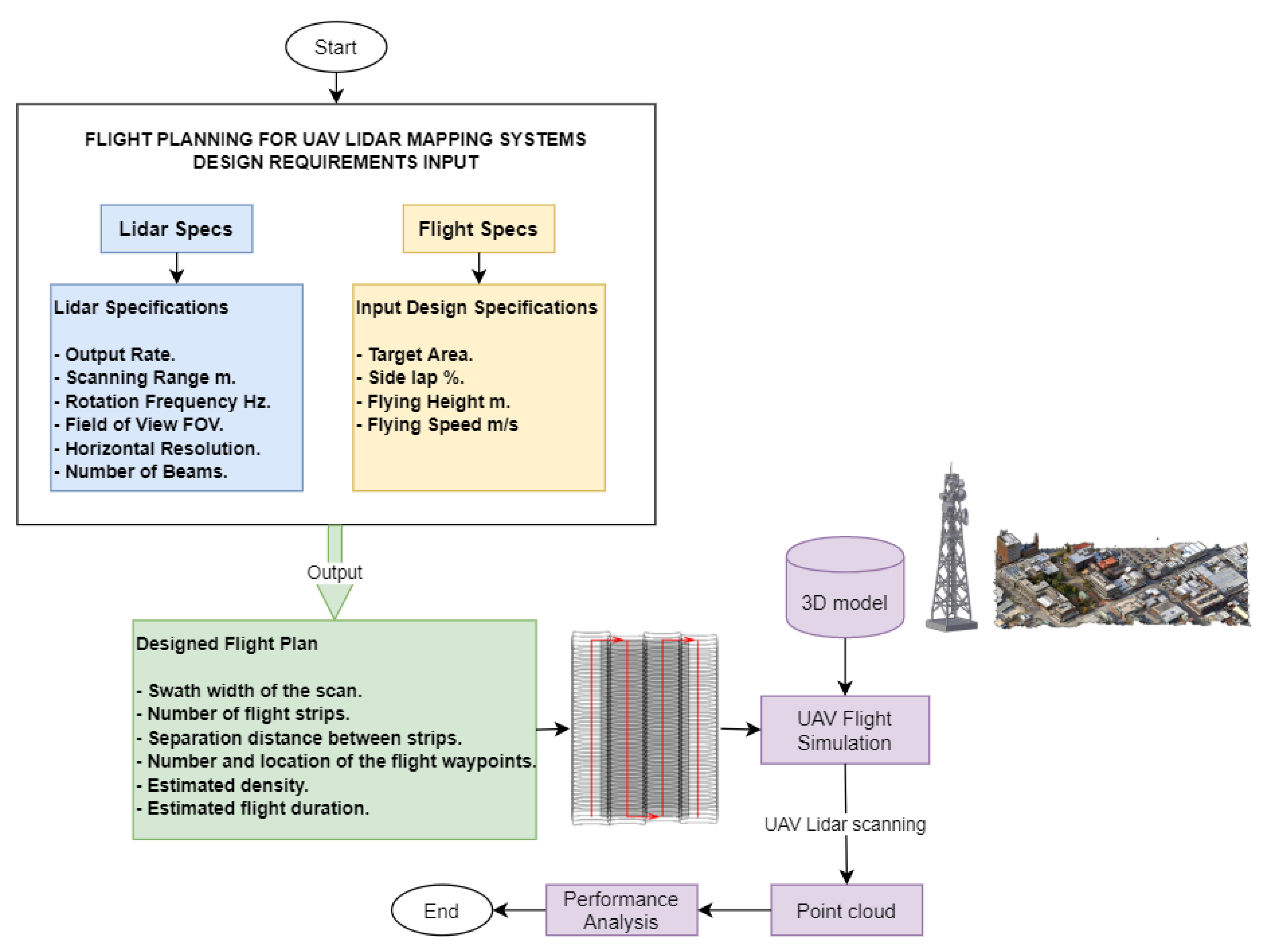
- Swath width of the scan
- Number of flight strips
- Separation distance between flight strips
- Number and location of the flight waypoints
- Estimated point density
- Estimated flight duration
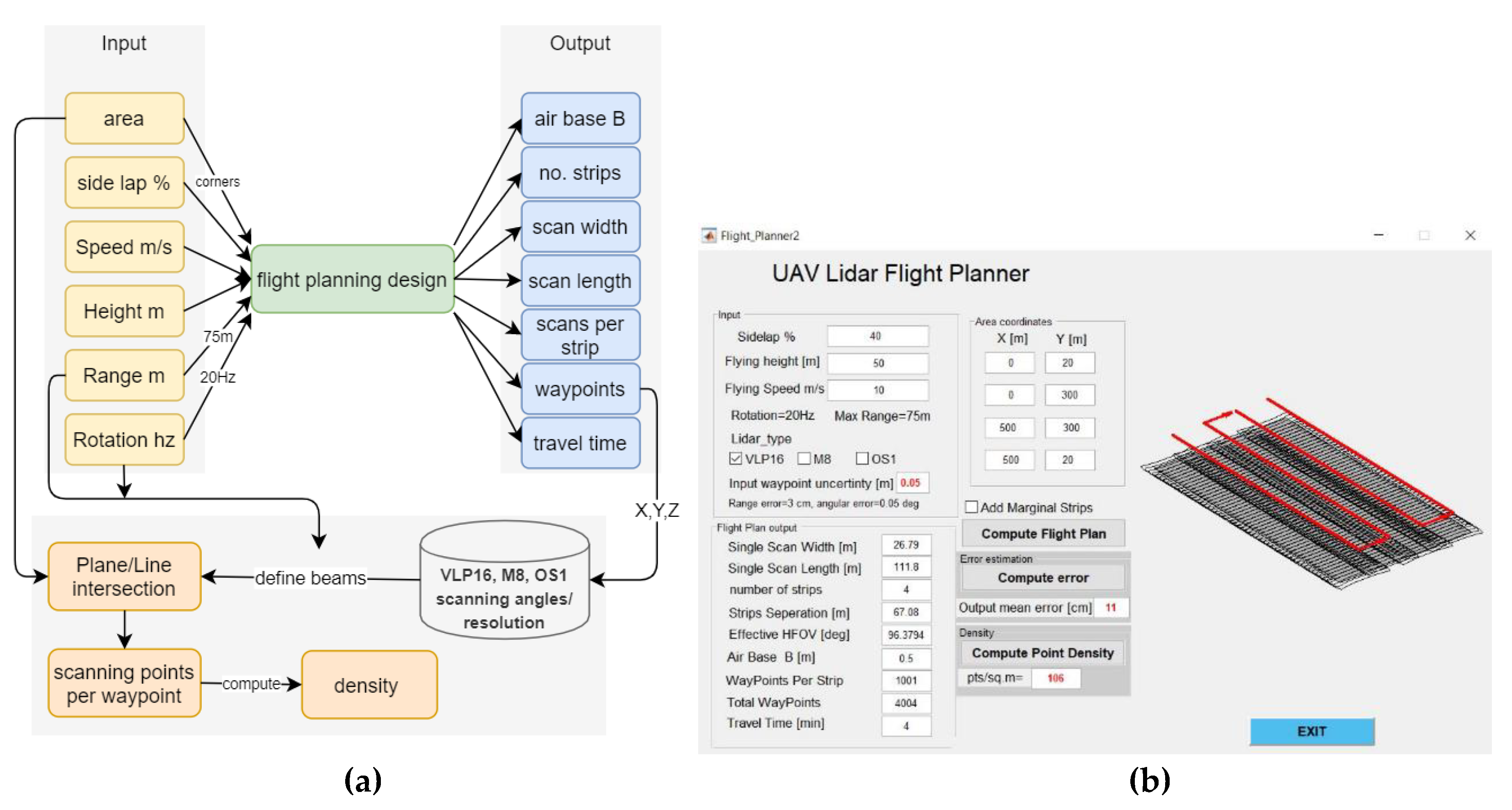
2.1. Flight Plan Design
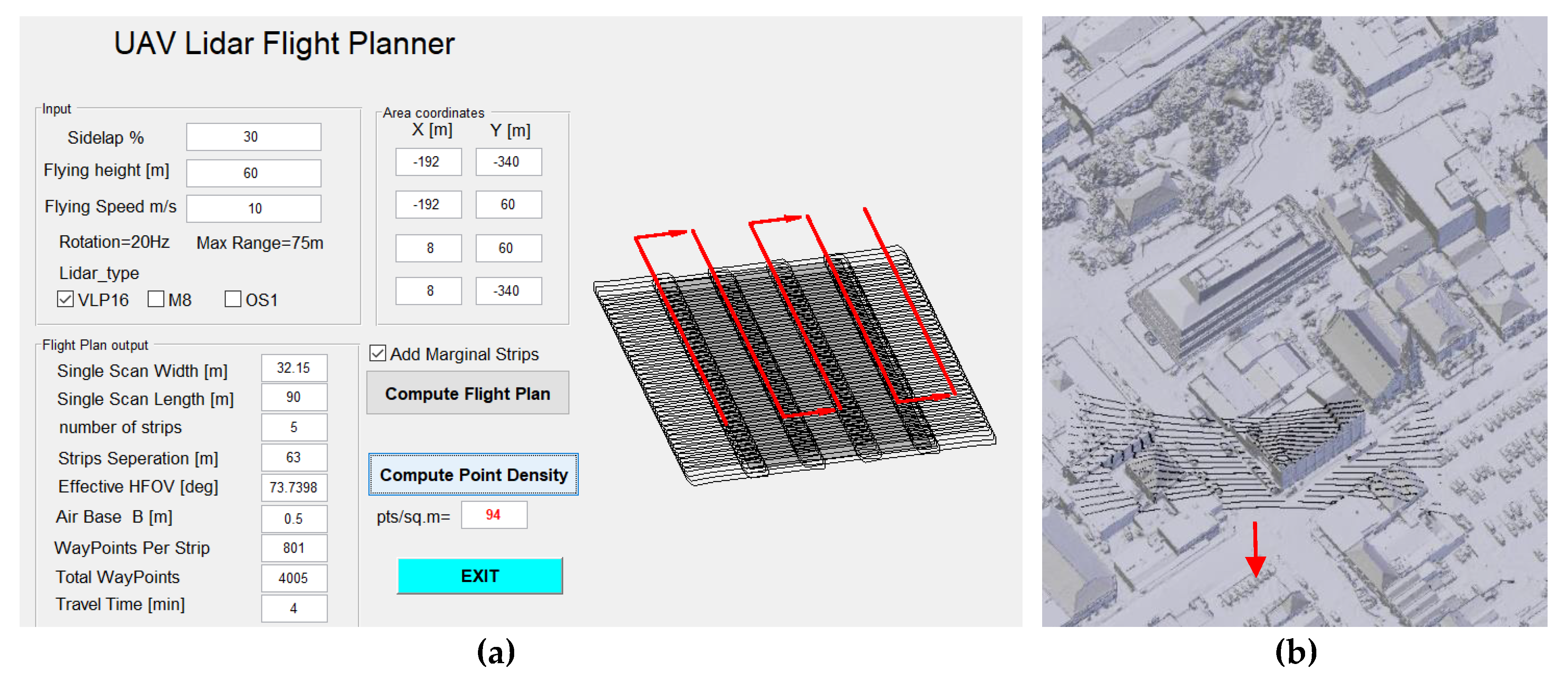
- LiDAR specifications: Every multi-beam LiDAR sensor has its own geometric structure, which includes FOV, angular distribution of beams, angular resolution, output rate pts/m2, rotation speed, and the maximum scanning range. Table 1 shows the characteristics of the three selected low-cost multi-beam LiDAR sensors, as published by their manufacturers [35,36,37].
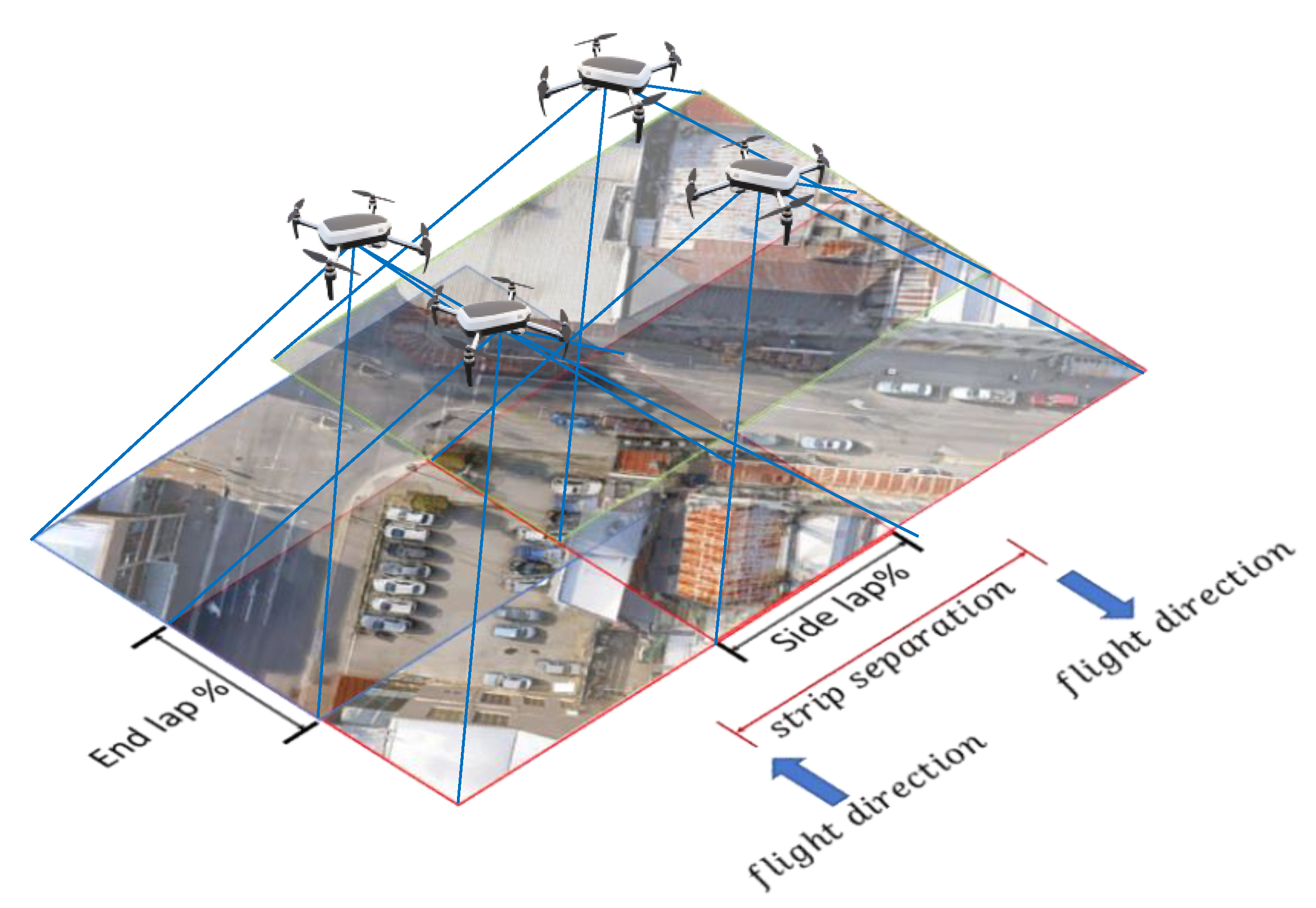
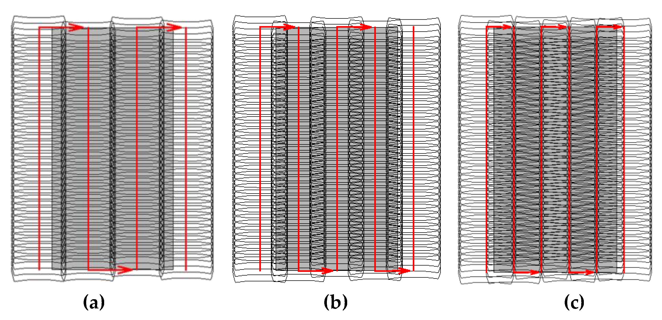
- Flight plan specifications: They include flying height H, flying speed m/s, and the required sidelap % between adjacent scanning strips. It should be noted that a larger overlap percentage ensures higher coverage but requires a longer flight time, which should be carefully considered.
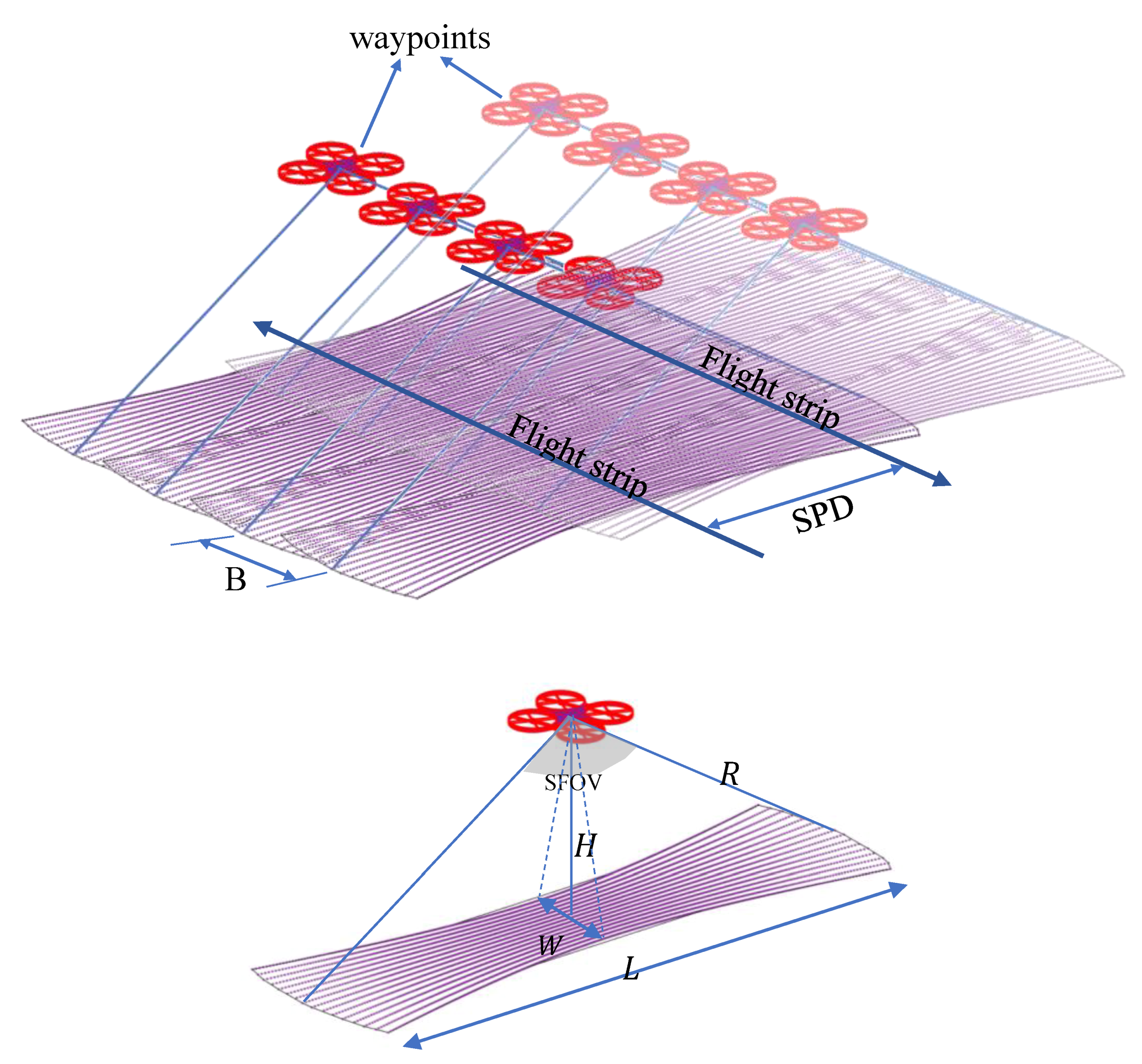
- : project area dimensions defined as a rectangle with a length and width .
- flying height above the ground level.
- scanning range of the LiDAR.
- distance between two successive waypoints.
- : along track scanning width.
- : across track swath width of the scanning.
- : scanning field of view out of the offered 360° FOV.
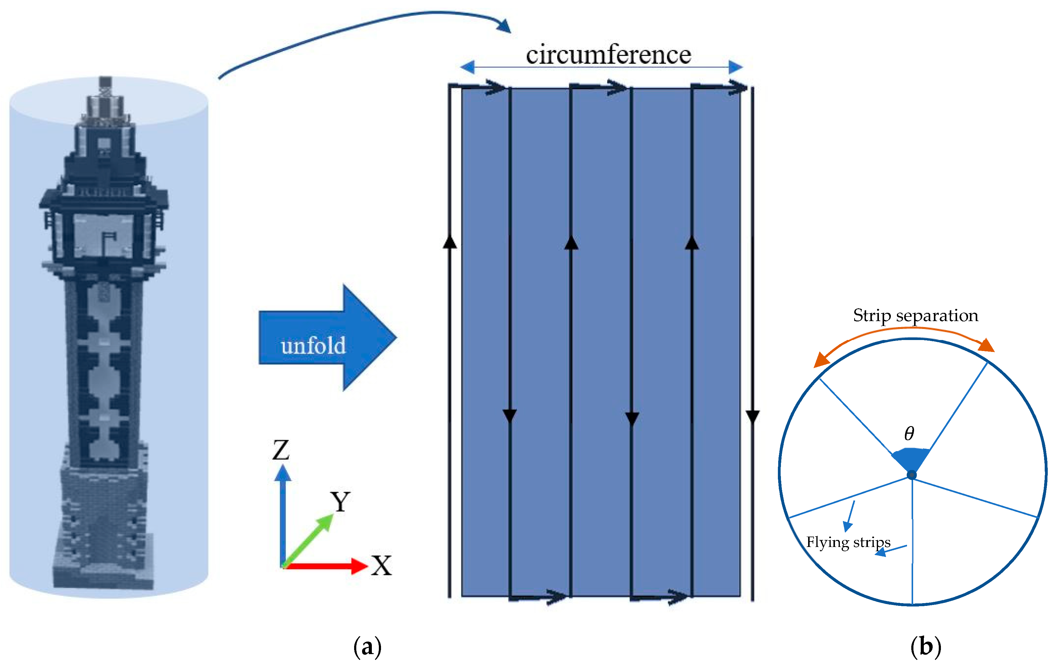
- : separation distance between the flight strips.
- : number of flight strips rounded to positive infinity.
- number of waypoints per strip.
2.2. Scanning Simulation
- : the measured range distance from the LiDAR to the object points.
- : rotation matrix of the boresight angles.
- : the measured azimuth angle of the laser beam.
- : the vertical angle of the laser beam measured from the horizon.
- , and : the coordinates of the LiDAR sensor.
- and : the coordinates of the scanned point.
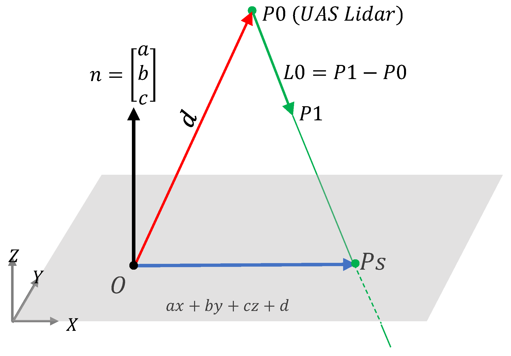
- -
- Compute the scan vector from the LiDAR to the object direction point . This vector might intersect the simulated object before or after at (Figure 5).
- -
- Define the object plane normal by the parameters.
- -
- Compute the vector = Dot product), which should be a non-zero value if the LiDAR beam line and the object plane are not parallel and should intersect at a unique object point .
3. Results and Discussion
3.1. Flight Planning Tool
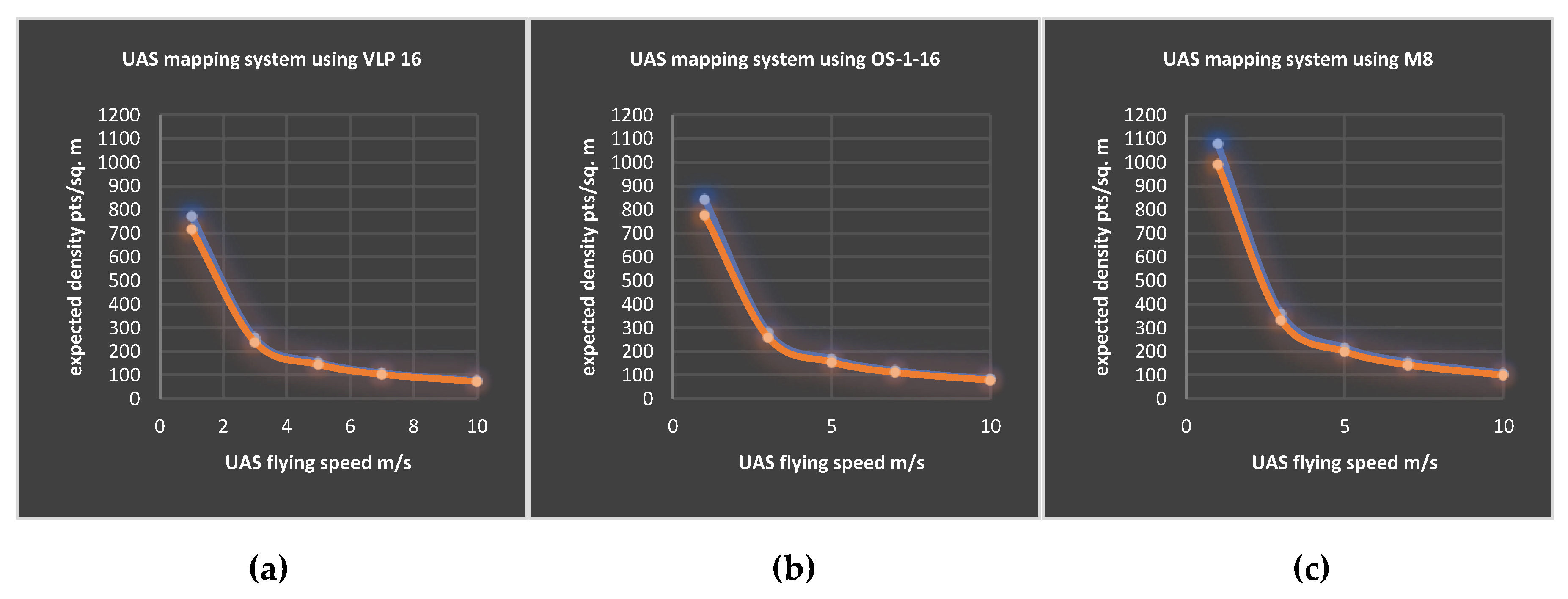
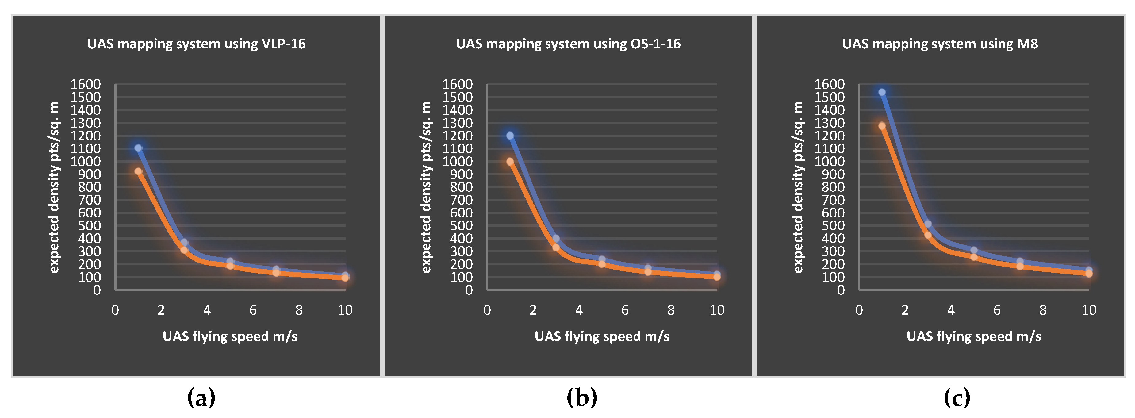
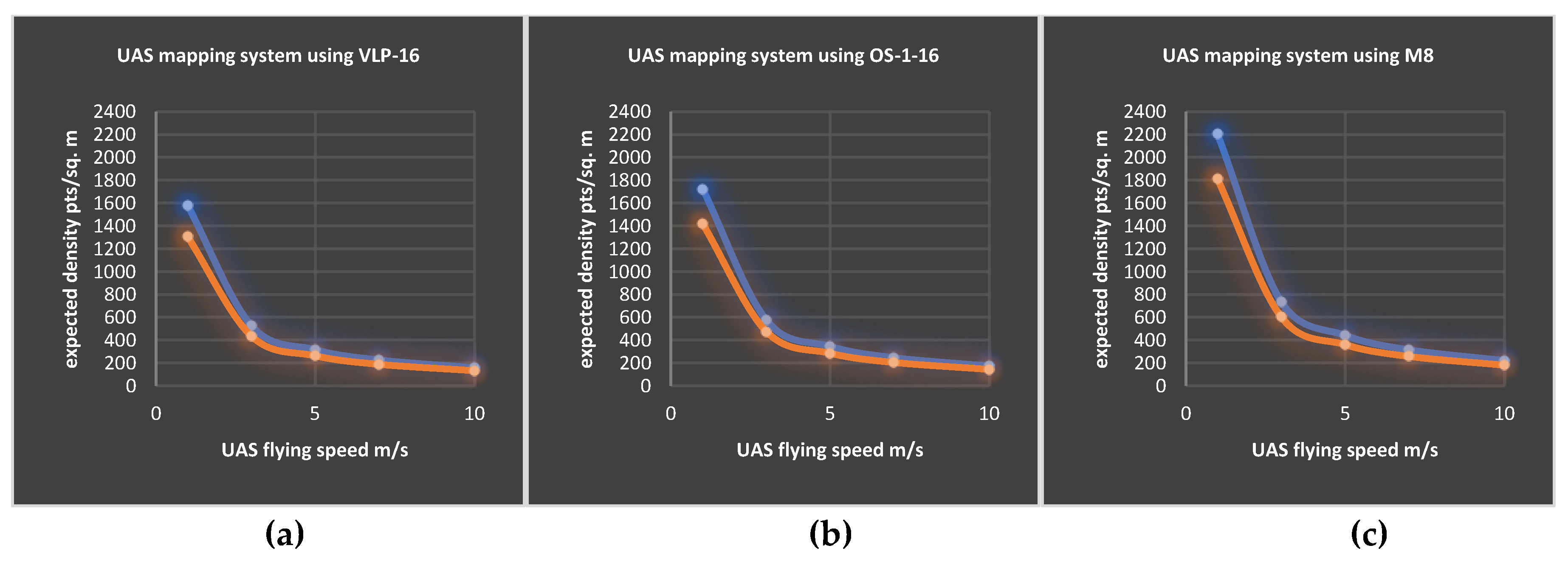
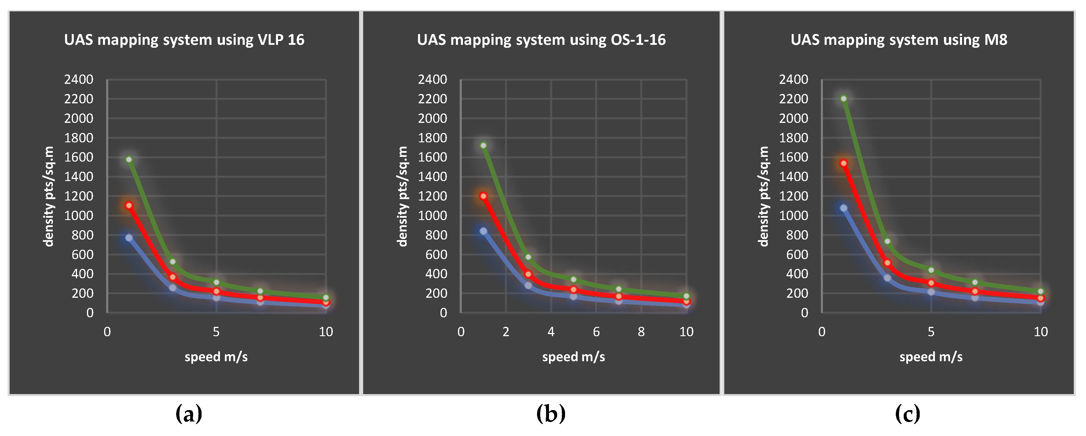
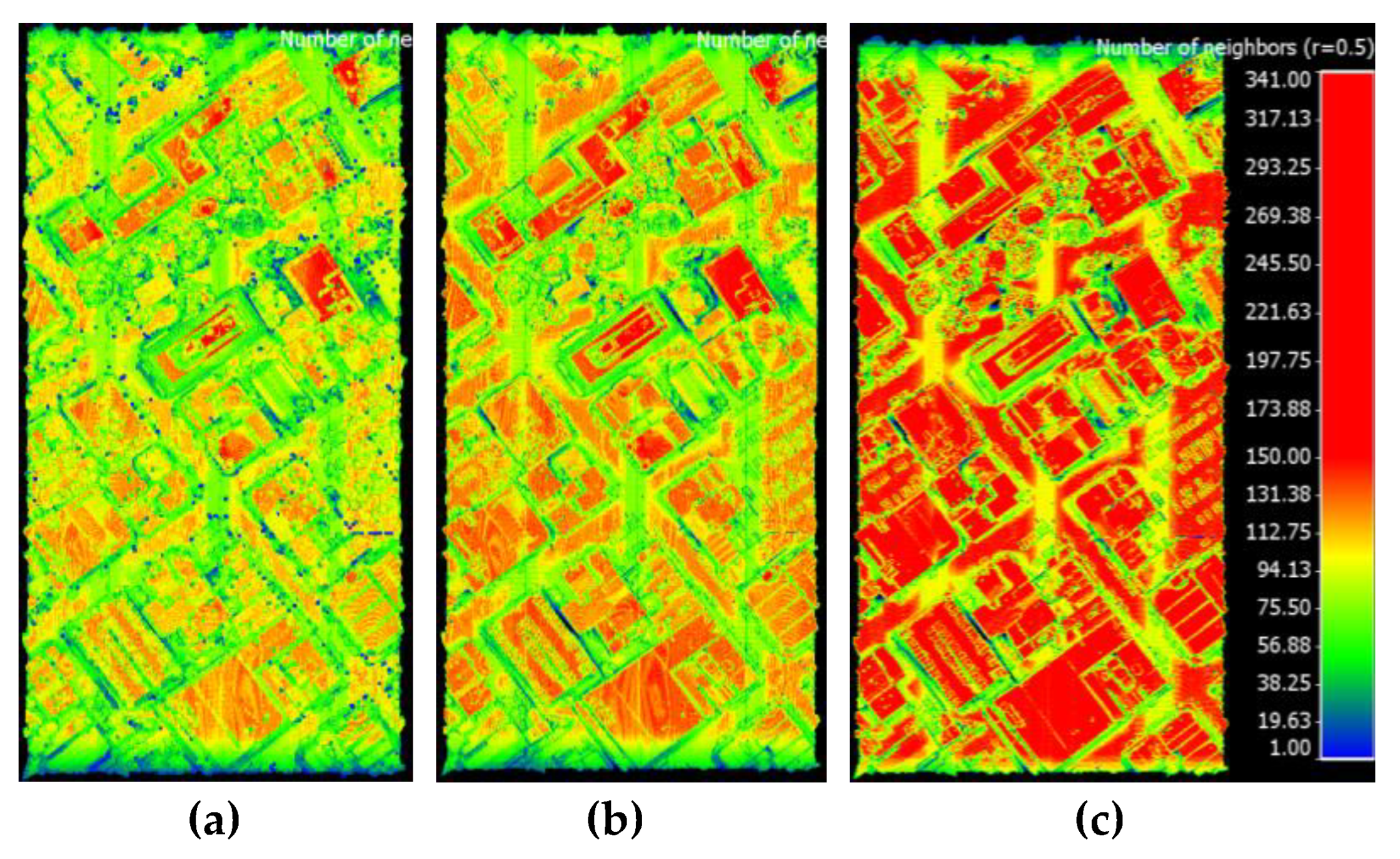
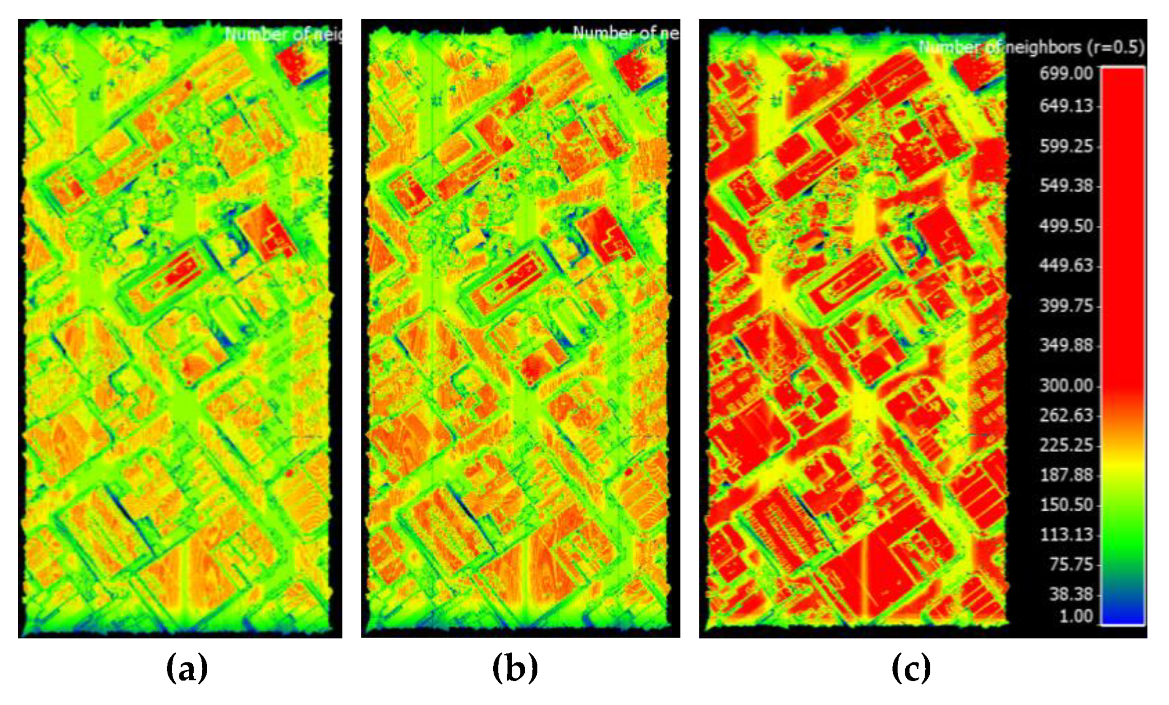
3.2. Estimated Average Point Density
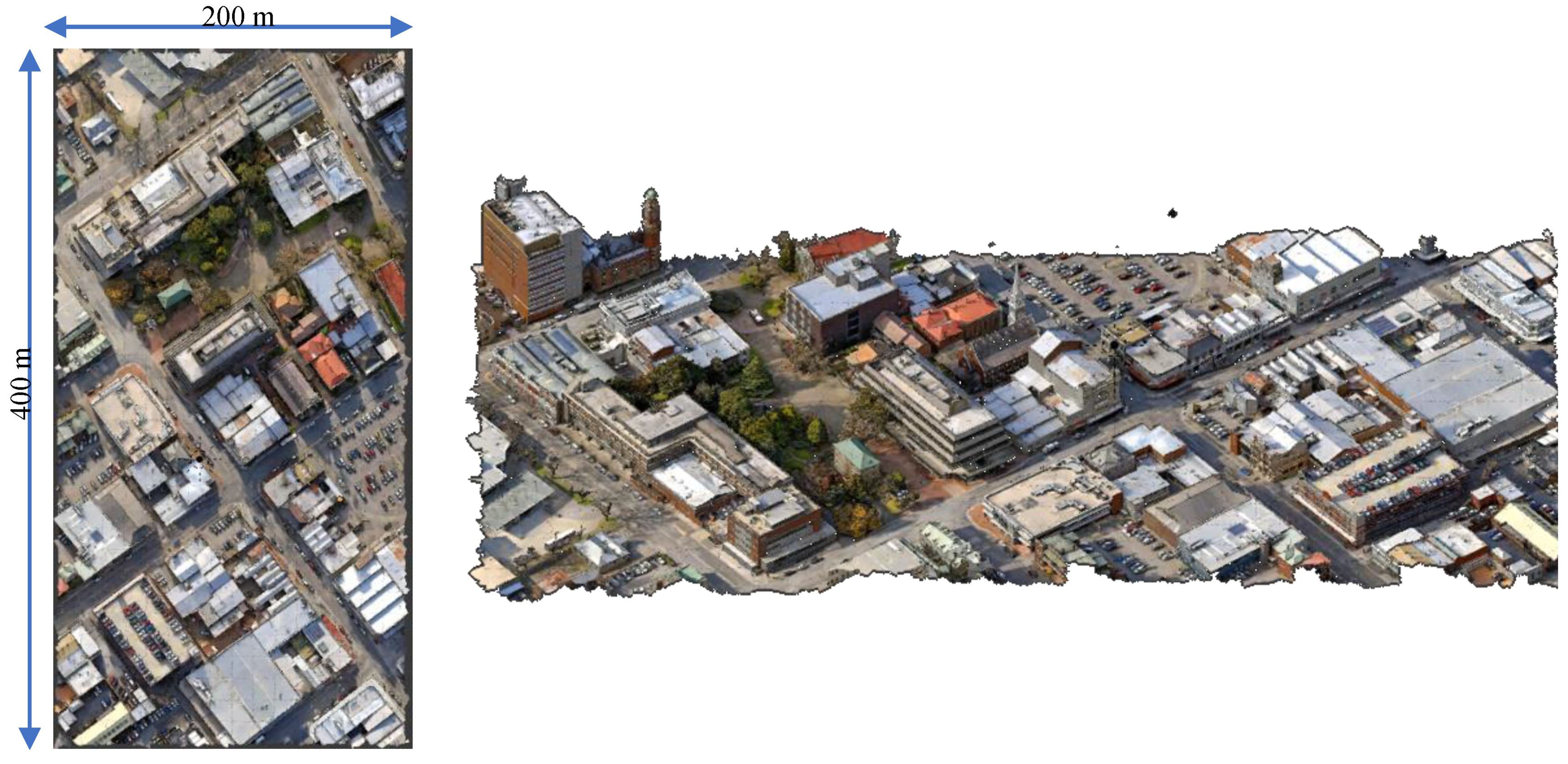
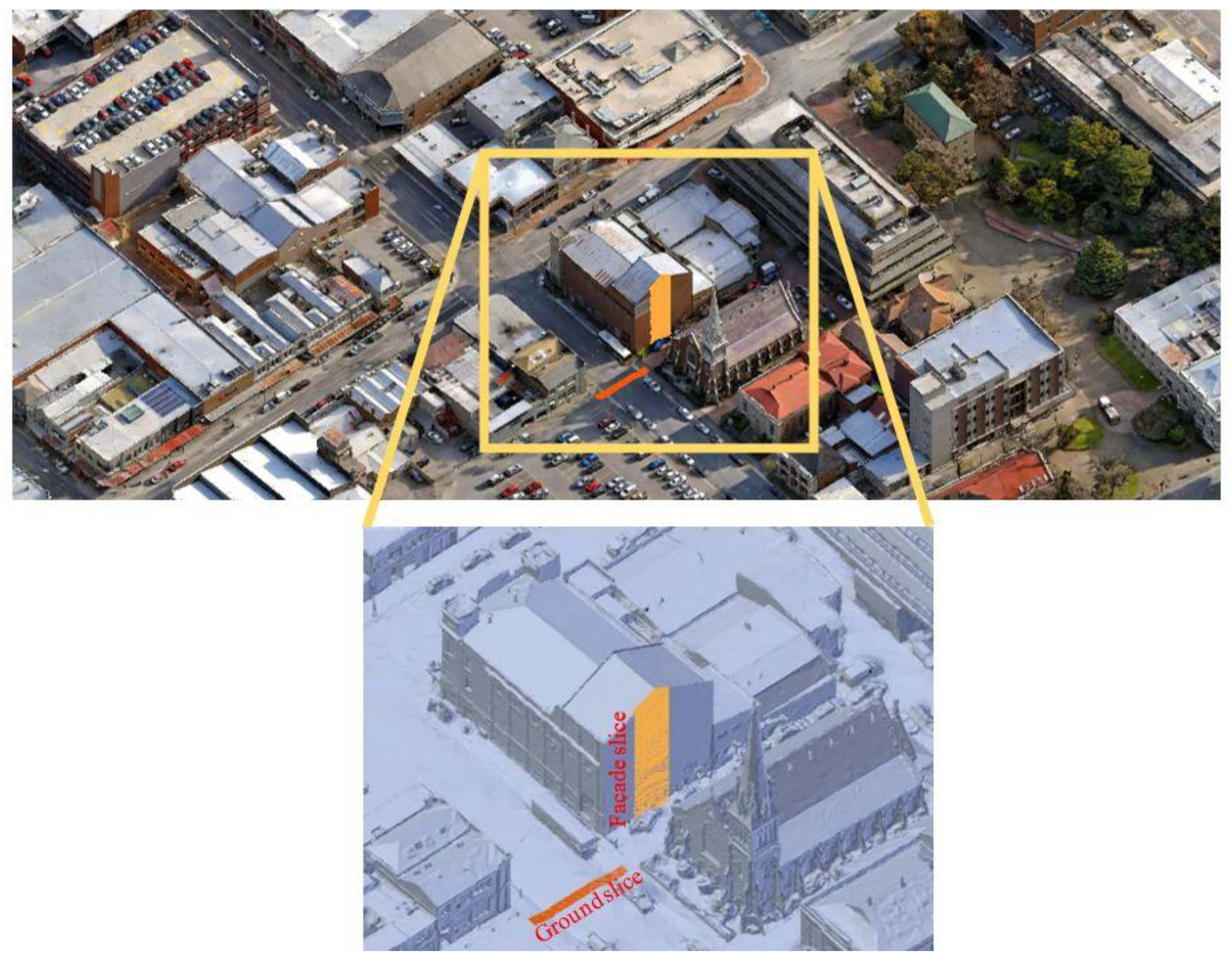
3.3. UAS LiDAR Mapping of an Urban Area
- -
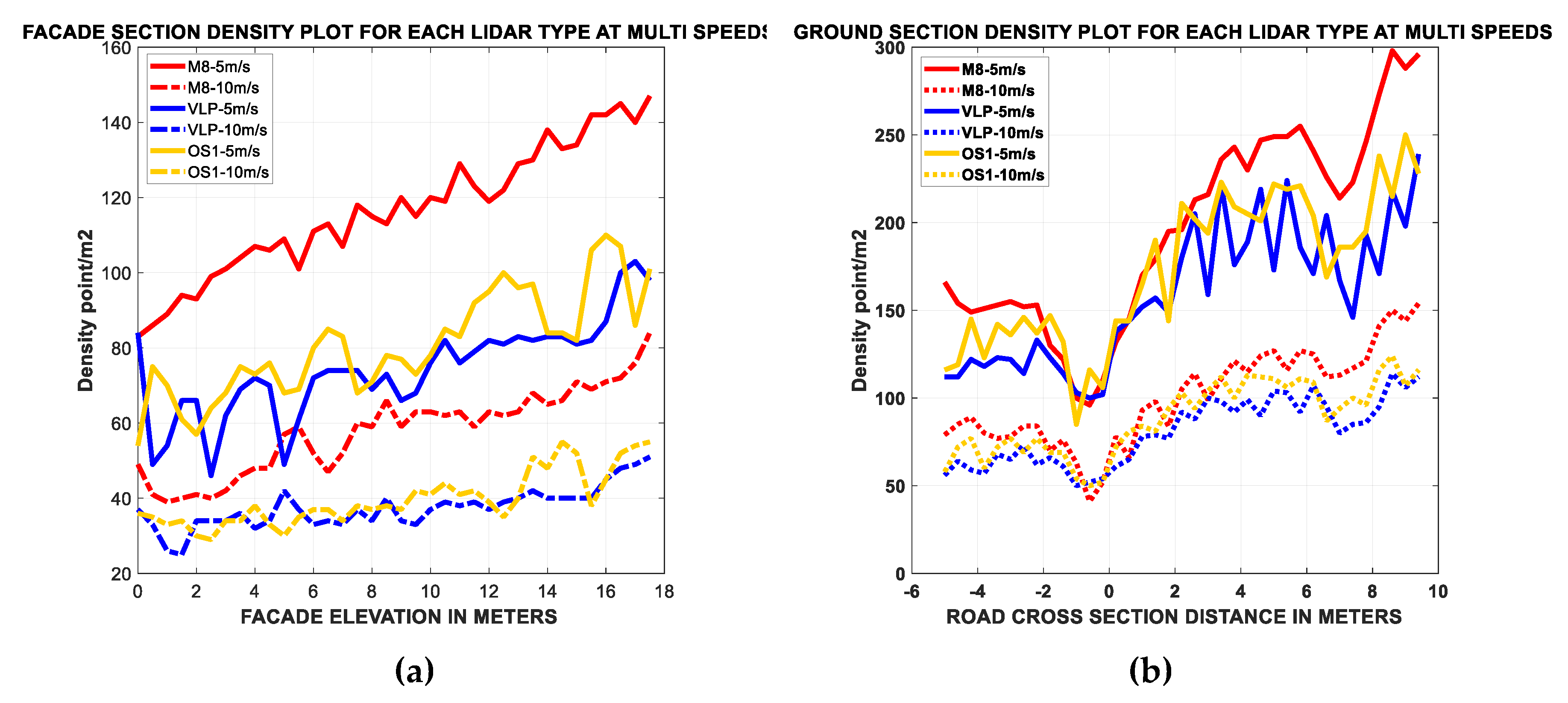
- In contrary to the image-based UAS missions, even with the nadir orientation of the LiDAR, a significant coverage and point density on building facades could be attained.
- -
- M8 had a higher performance than VLP-16 LiDAR and OS-1-16, especially on facade features.
- -
- Density achieved on facades was approximately half the density achieved on the ground and roof features.
- -
- Ouster OS-1-16 slightly outperformed the VLP-16 LiDAR on the ground and facades.
- -
- The density achieved on facades was better at the high altitude parts than the lower altitude parts.
- -
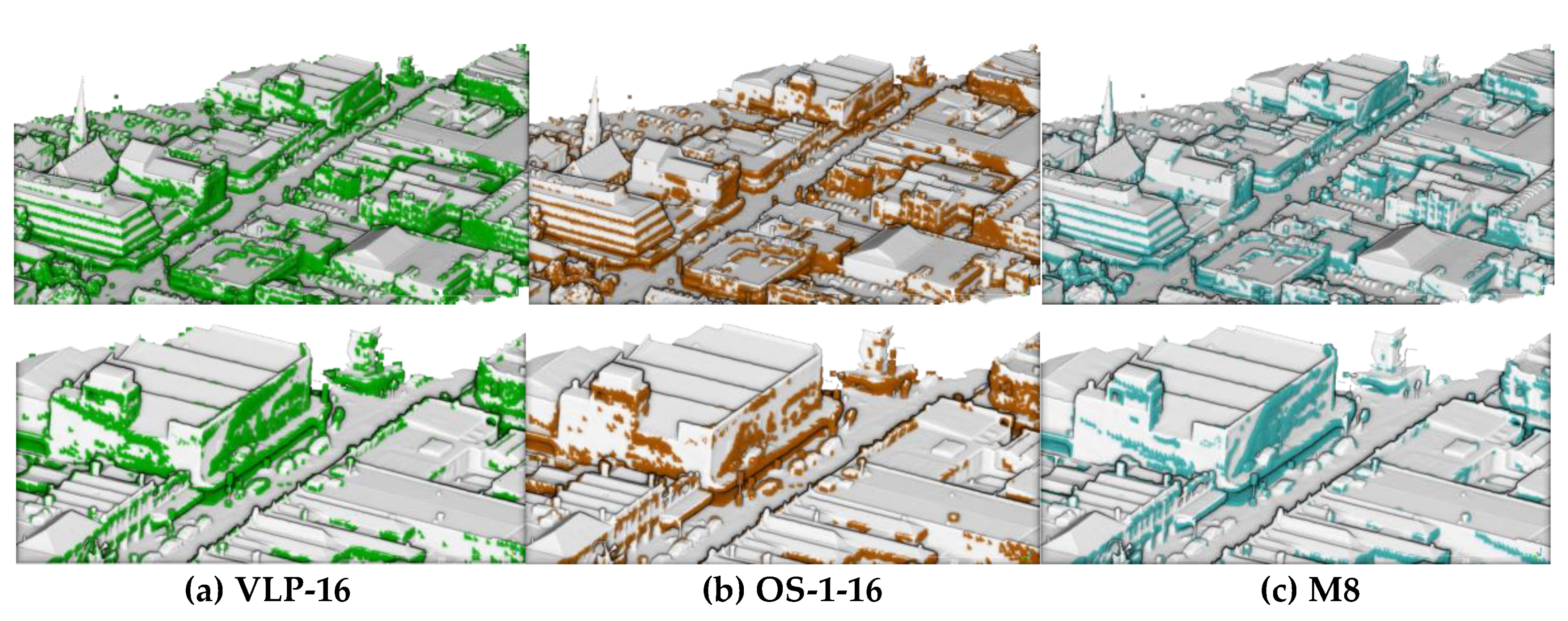
- Sample the reference model as a point cloud with a uniform spacing of 10 cm.
- -
- For every point in the reference point cloud, find any scanning point within a 25 cm search radius.
- -
- Label reference points as “covered” if they have a neighboring scanned point, or “uncovered” if there are distant scanned points (≥25 cm).
- -
- Use the “uncovered” points as an indicator of completeness.
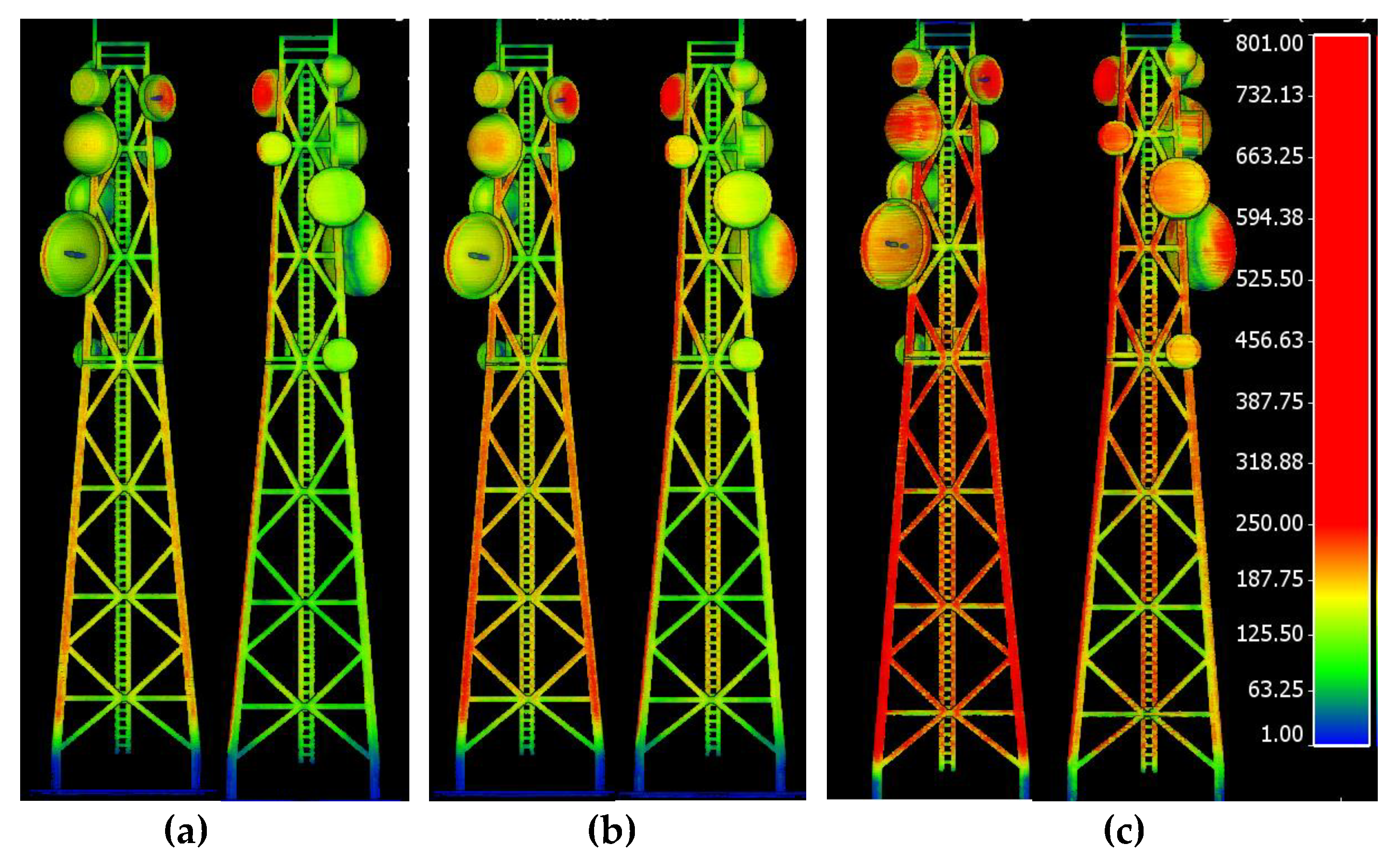
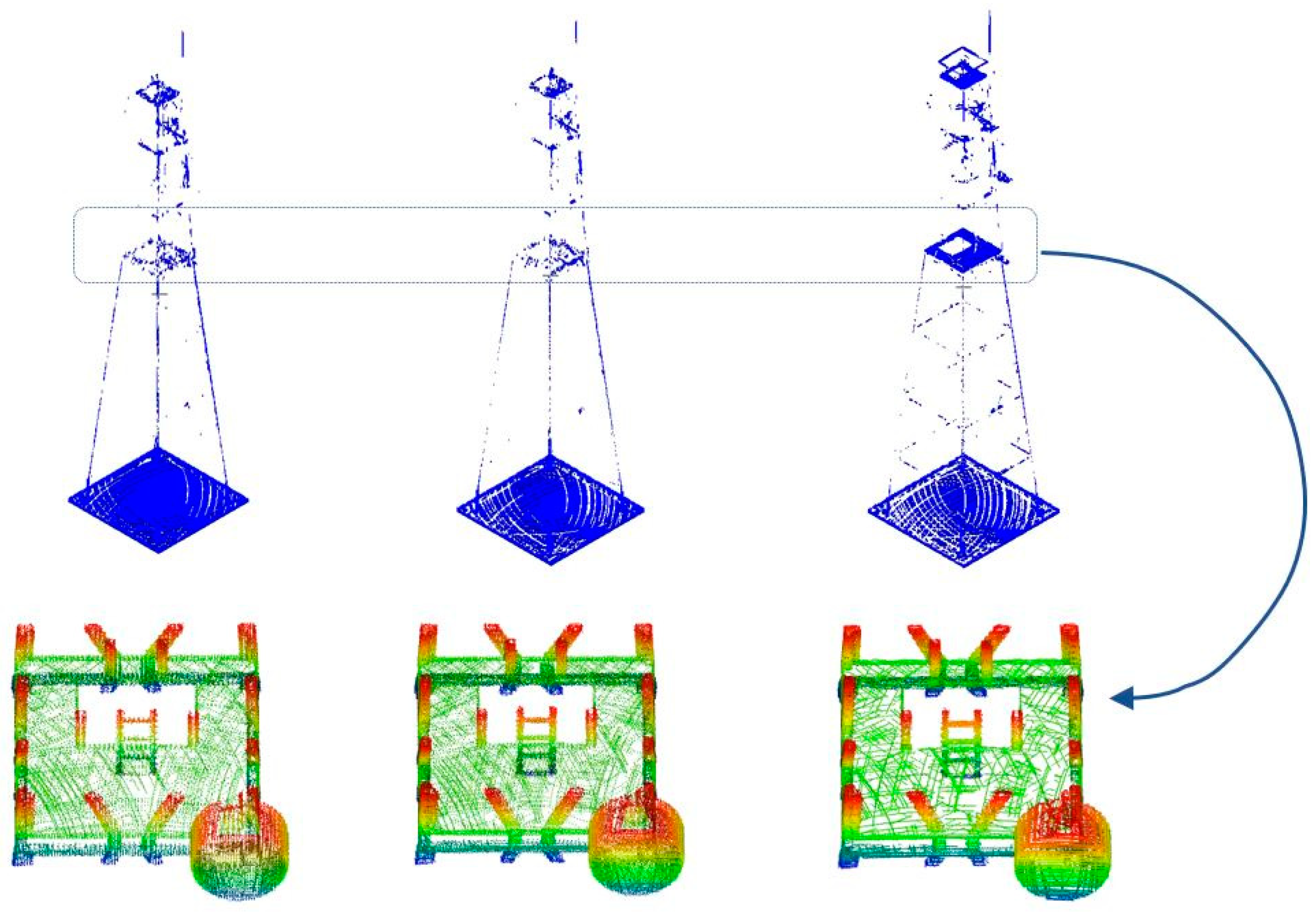
3.4. UAS LiDAR Mapping of a Communication Tower
4. Conclusions
Author Contributions
Funding
Conflicts of Interest
References
- Hassanalian, M.; Abdelkefi, A. Classifications, applications, and design challenges of drones: A review. Prog. Aerosp. Sci. 2017, 91, 99–131. [Google Scholar] [CrossRef]
- Colomina, I.; Molina, P. Unmanned aerial systems for photogrammetry and remote sensing: A review. ISPRS J. Photogramm. Remote Sens. 2014, 92, 79–97. [Google Scholar] [CrossRef]
- Nex, F.; Remondino, F. UAV for 3D mapping applications: A review. Appl. Geomat. 2014, 6, 1–15. [Google Scholar] [CrossRef]
- Granshaw, S.I. RPV, UAV, UAS, RPAS … or just drone? Photogramm. Rec. 2018, 33, 160–170. [Google Scholar] [CrossRef]
- SkyIMD’s Online Flight Planner. Available online: http://www.skyimd.com/online-flight-planner-for-aerial-imaging-mapping-survey/ (accessed on 7 June 2020).
- Pix4Dcapture. Available online: https://www.pix4d.com/product/pix4dcapture (accessed on 7 June 2020).
- Oborne, M. Mission Planner. Available online: https://ardupilot.org/planner/index.html (accessed on 7 June 2020).
- UgCS Software. Available online: https://heighttech.nl/flight-planning-software/ (accessed on 7 June 2020).
- Flight Planning Software for DJI Drones. Available online: https://www.djiflightplanner.com/ (accessed on 7 June 2020).
- Drone Mapping. Available online: https://solvi.nu/ (accessed on 7 June 2020).
- eMotion. Available online: https://www.sensefly.com/software/emotion/ (accessed on 7 June 2020).
- mdCOCKPIT DESKTOP SOFTWARE. Available online: https://www.microdrones.com/en/integrated-systems/software/mdcockpit/ (accessed on 7 June 2020).
- UAV Toolbox. Available online: http://uavtoolbox.com/ (accessed on 7 June 2020).
- UgCS Photogrammetry. Available online: https://www.ugcs.com/ (accessed on 7 June 2020).
- Almadhoun, R.; Abduldayem, A.; Taha, T.; Seneviratne, L.; Zweiri, Y. Guided Next Best View for 3D Reconstruction of Large Complex Structures. Remote Sens. 2019, 11, 2440. [Google Scholar] [CrossRef]
- Papadopoulos-Orfanos, D.; Schmitt, F. Automatic 3-D digitization using a laser rangefinder with a small field of view. In Proceedings of the International Conference on Recent Advances in 3-D Digital Imaging and Modeling (Cat. No.97TB100134), Ottawa, ON, Canada, 12–15 May 1997; pp. 60–67. [Google Scholar]
- Scott, W.R.; Roth, G.; Rivest, J.-F. View planning for automated three-dimensional object reconstruction and inspection. ACM Comput. Surv. 2003, 35, 64–96. [Google Scholar] [CrossRef]
- Skydio Inc. Available online: https://www.skydio.com/ (accessed on 7 June 2020).
- Mendoza, M.; Vasquez-Gomez, J.; Taud, H. NBV-Net: A 3D Convolutional Neural Network for Predicting the Next-Best-View. 2018. Available online: https://github.com/irvingvasquez/nbv-net (accessed on 7 June 2020).
- Vasquez-Gomez, J.I.; Sucar, L.E.; Murrieta-Cid, R.; Lopez-Damian, E. Volumetric Next-best-view Planning for 3D Object Reconstruction with Positioning Error. Int. J. Adv. Rob. Syst. 2014, 11, 159. [Google Scholar] [CrossRef]
- Haner, S.; Heyden, A. Optimal View Path Planning for Visual SLAM; Springer: Berlin/Heidelberg, Germany, 2011; pp. 370–380. [Google Scholar]
- Anthony, D.; Elbaum, S.; Lorenz, A.; Detweiler, C. On crop height estimation with UAVs. In Proceedings of the 2014 IEEE/RSJ International Conference on Intelligent Robots and Systems, Chicago, IL, USA, 14–18 September 2014; pp. 4805–4812. [Google Scholar]
- Teng, G.E.; Zhou, M.; Li, C.R.; Wu, H.H.; Li, W.; Meng, F.R.; Zhou, C.C.; Ma, L. MINI-UAV LIDAR FOR POWER LINE INSPECTION. Int. Arch. Photogramm. Remote Sens. Spatial Inf. Sci. 2017, XLII-2/W7, 297–300. [Google Scholar] [CrossRef]
- Brede, B.; Lau, A.; Bartholomeus, H.M.; Kooistra, L. Comparing RIEGL RiCOPTER UAV LiDAR Derived Canopy Height and DBH with Terrestrial LiDAR. Sensors 2017, 17, 2371. [Google Scholar] [CrossRef] [PubMed]
- Mandlburger, G.; Pfennigbauer, M.; Schwarz, R.; Flöry, S.; Nussbaumer, L. Concept and Performance Evaluation of a Novel UAV-Borne Topo-Bathymetric LiDAR Sensor. Remote Sens. 2020, 12, 986. [Google Scholar] [CrossRef]
- Santiago, R.; Maria, B.-G. An Overview of Lidar Imaging Systems for Autonomous Vehicles. Appl. Sci. 2019, 9, 4093. [Google Scholar]
- A Complete Guide to LiDAR: Light Detection and Ranging. Available online: https://gisgeography.com/lidar-light-detection-and-ranging/ (accessed on 7 June 2020).
- Snoopy UAV LiDAR System. Available online: https://www.lidarusa.com/products.html (accessed on 7 June 2020).
- UAV LiDAR System. Available online: https://www.routescene.com/the-3d-mapping-solution/uav-lidar-system/ (accessed on 7 June 2020).
- YellowScan Surveyor. Available online: https://www.yellowscan-lidar.com/products/surveyor/ (accessed on 7 June 2020).
- Geo-MMS LiDAR. Available online: https://geodetics.com/product/geo-mms/ (accessed on 7 June 2020).
- SCOUT-16. Available online: https://www.phoenixlidar.com/scout-16/ (accessed on 7 June 2020).
- Geo-MMS: From Flight Mission to Drone Flight Planning. Available online: https://geodetics.com/drone-flight-planning/ (accessed on 7 June 2020).
- PHOENIX FLIGHT PLANNER. Available online: https://www.phoenixlidar.com/flightplan/ (accessed on 7 June 2020).
- Quanergy. Available online: https://quanergy.com/ (accessed on 7 June 2020).
- Ouster. Available online: https://ouster.com/ (accessed on 7 June 2020).
- Velodyne Lidar. Available online: https://velodynelidar.com/ (accessed on 7 June 2020).
- Blender. Available online: http://www.blender.org (accessed on 7 June 2020).
- Launceston City 3D Model. Available online: http://s3-ap-southeast-2.amazonaws.com/launceston/atlas/index.html (accessed on 7 June 2020).
- Alsadik, B. Adjustment Models in 3D Geomatics and Computational Geophysics: With MATLAB Examples; Elsevier Science: Amsterdam, The Netherlands, 2019. [Google Scholar]
- Gordon, S.J.; Lichti, D.D. Terrestrial Laser Scanners with A Narrow Field of View: The Effect on 3D Resection Solutions. Surv. Rev. 2004, 37, 448–468. [Google Scholar] [CrossRef]
- Intersection of Lines and Planes. Available online: http://geomalgorithms.com/a05-_intersect-1.html] (accessed on 15 January 2020).
- CloudCompare. CloudCompare: 3D Point Cloud and Mesh Processing Software. Available online: https://www.danielgm.net/cc/ (accessed on 7 June 2020).
- FormAffinity. Communication Tower. Available online: https://www.turbosquid.com/3d-models/free-max-mode-communication-tower/735405 (accessed on 7 June 2020).


| LiDAR Sensor/System | Velodyne [37] | Quanergy [35] | Ouster [36] |
|---|---|---|---|
| Type/version | VLP-16 | M8 | OS-1-16 |
| Max. Range | ≤ 100 m | > 100 m @ 80% | ≤ 120 m @ 80% |
| Range Accuracy 1σ | ±3 cm (Typical) | ±3 cm | ±1.5-10 cm |
| Output rate pts/sec. | ≈300000 | ≈420000 (1 return) | ≈327680 |
| FOV - Vertical | ≈30° (±15°) | ≈20° (+3°/–17°) | ≈33.2° (±16.6°) |
| Rotation rate | 5-20 Hz | 5-20 Hz | 10-20 Hz |
| Vertical resolution | V:2° | V:3° | V: 2.2° |
| Horizontal resolution | H: 0.4°@ 20Hz | H: 0.14°@ 20Hz | H:0.35°@ 20Hz |
| Weight | 830 g | 900 g | 425 g |
| Power consumption | 8 w | 18 w | 14-20 w |
| Price | $8K | $5K | $3.5K |
| Speed @ 10 m/s | Speed @ 5 m/s | |||
|---|---|---|---|---|
| Facades and Trees | Ground and Horizontal Surfaces | Facades and Trees | Ground and Horizontal Surfaces | |
| M8 | 81 | 131 | 162 | 260 |
| OS1-1-16 | 64 | 105 | 127 | 207 |
| VLP-16 | 58 | 98 | 116 | 192 |
| LiDAR Type | Density pts/m2 | Lack of Coverage |
|---|---|---|
| VLP-16 | 162 ± 62 | 11.1 % |
| OS-1-16 | 184 ± 70 | 8.2 % |
| M8 | 235 ± 93 | 7.6 % |
© 2020 by the authors. Licensee MDPI, Basel, Switzerland. This article is an open access article distributed under the terms and conditions of the Creative Commons Attribution (CC BY) license (http://creativecommons.org/licenses/by/4.0/).
Share and Cite
Alsadik, B.; Remondino, F. Flight Planning for LiDAR-Based UAS Mapping Applications. ISPRS Int. J. Geo-Inf. 2020, 9, 378. https://doi.org/10.3390/ijgi9060378
Alsadik B, Remondino F. Flight Planning for LiDAR-Based UAS Mapping Applications. ISPRS International Journal of Geo-Information. 2020; 9(6):378. https://doi.org/10.3390/ijgi9060378
Chicago/Turabian StyleAlsadik, Bashar, and Fabio Remondino. 2020. "Flight Planning for LiDAR-Based UAS Mapping Applications" ISPRS International Journal of Geo-Information 9, no. 6: 378. https://doi.org/10.3390/ijgi9060378
APA StyleAlsadik, B., & Remondino, F. (2020). Flight Planning for LiDAR-Based UAS Mapping Applications. ISPRS International Journal of Geo-Information, 9(6), 378. https://doi.org/10.3390/ijgi9060378


