Article

3D Space Shift from CityGML LoD3-Based Multiple Building Elements to a 3D Volumetric Object

1
School of Resource and Environmental Sciences, Wuhan University, Wuhan 430079, China
2
Urban Planning, Land and Resources Commission of Shenzhen Municipality, Shenzhen 518034, China
3
Key Laboratory of Geographic Information System (Wuhan University), Ministry of Education, Wuhan 430079, China
4
Shenzhen Research Centre of Digital City Engineering, Shenzhen 518034, China
5
Key Laboratory of Urban Land Resources Monitoring and Simulation, Ministry of Land and Resources, Shenzhen 518034, China
6
Research Institute for Smart Cities, Shenzhen University, Shenzhen 518060, China
*
Author to whom correspondence should be addressed.
ISPRS Int. J. Geo-Inf. 2017, 6(1), 17; https://doi.org/10.3390/ijgi6010017
Submission received: 22 August 2016 / Revised: 5 January 2017 / Accepted: 7 January 2017 / Published: 15 January 2017

Abstract

:
In contrast with photorealistic visualizations, urban landscape applications, and building information system (BIM), 3D volumetric presentations highlight specific calculations and applications of 3D building elements for 3D city planning and 3D cadastres. Knowing the precise volumetric quantities and the 3D boundary locations of 3D building spaces is a vital index which must remain constant during data processing because the values are related to space occupation, tenure, taxes, and valuation. To meet these requirements, this paper presents a five-step algorithm for performing a 3D building space shift. This algorithm is used to convert multiple building elements into a single 3D volumetric building object while maintaining the precise volume of the 3D space and without changing the 3D locations or displacing the building boundaries. As examples, this study used input data and building elements based on City Geography Markup Language (CityGML) LoD3 models. This paper presents a method for 3D urban space and 3D property management with the goal of constructing a 3D volumetric object for an integral building using CityGML objects, by fusing the geometries of various building elements. The resulting objects possess true 3D geometry that can be represented by solid geometry and saved to a CityGML file for effective use in 3D urban planning and 3D cadastres.

1. Introduction and Motivations

Three-dimensional (3D) city models can be created using numerous techniques and have been widely applied in multiple fields such as city planning, architectural design, and wireless communication [1]. Various logical views of buildings exist. Architectural structures focus on building elements such as roofs, walls, or doors, while architectural design concentrates on the shapes and layout of building elements. Compared to real-time photorealistic visualizations, calculable 3D geometry presentations emphasize the specific properties of objects, using geometry to support the calculations and analyses. For buildings, such properties include 3D space, the building's volumetric quantity, and the locations of the building's 3D boundaries. In 3D urban planning and management fields, 3D cadastres [2,3,4,5] require the entire 3D closed volumetric space of a building to identify the precise space based on boundary points, lines, and faces, with a particular focus on the outer boundaries of the buildings. This volume is an important index used to determine the space occupied by a property to assist with 3D space management and property tax assessments. In a 3D cadastre, a 3D parcel is defined as the spatial unit against which unique and homogeneous rights are associated with the entire entity [2]; however, the legal aspects of 3D cadastres are out of the scope of this paper. 3D cadastres aim to manage the 3D space of 3D parcels by using 3D geometry to represent the 3D property unit. More importantly, this volume of 3D space is not allowed to change during data processing because it relates to the parcel's space occupation, tenure, taxes, and valuation. Small geometric errors in the building models may lead to large errors in the computed volumes [6]. Therefore, during 3D volumetric construction from 3D data to 3D geometry, the boundaries of buildings cannot be changed.
Due to the logical criteria involved in 3D cadastres and other applications, this paper aims to represent a building as a single object with closed faces and a computable volume to satisfy the requirements of 3D cadastres and other applications in this paper. BIMs (Building Information Models) have attracted wide attention; consequently, a large amount of BIM data (IFC and City Geography Markup Language (CityGML) LoD3) has been generated. BIMs provide precise data that describe building elements using coordinates and geometrics, and these can be used to derive the 3D boundaries for cadastres. The building elements represented in CityGML LoD3 are used as input data to calculate the 3D building space. This process serves to transfer the geometric structure, which improves the ability to analyse and compute 3D objects. We present a five-step algorithm for 3D volumetric construction and simplification of a CityGML object and then use it to convert multiple CityGML LoD3 objects into a 3D volumetric building space. The result is the simplest 3D geometry—a 3D volumetric solid that best fits the original object shape and maintains the precise volume of the original 3D building space.

2. Related Work

For different application purposes, users have various objectives when building models for real-world applications; consequently, they also have corresponding requirements for geometric representations and suitable simplification methods. Urban energy consumption for heating is directly correlated with the enveloped volume of buildings [7]. To precisely estimate energy consumption, Krüger and Kolbe [8] derived key indicators for analysing building heat energy requirements from 3D models of Berlin and integrated them with CityGML building models to realize the CityGML Energy ADE (Application Domain Extensions). Such applications have a common thread: the buildings are assumed to be 3D closed volumetric objects for which a volume can be computed. To meet the requirements of real-world applications of 3D volumetric objects, scholars have proposed building simplification algorithms based on 3D city data. Many studies have focused on creating 3D city models (e.g., [9]) and transforming the building elements at different levels of detail (LoDs) (e.g., [10,11,12]). Other studies have created methods to simplify and generalize the building models in a 3D environment. These studies have focused on such tasks as constructing 3D shapes by extruding ground footprints of 3D buildings [3,13] or simplifying 2D methods such as edge deletion or modification [12,14,15,16]. However, these methods have limited application to 3D buildings with a single vertical facade (wall) and are not suitable for many real building shapes. Another aspect is 3D shape simplification and generalization of buildings [15,17,18,19,20,21], employing various LoDs in visualization applications. However, these methods change the boundaries and locations of the 3D coordinates, which is not allowed for 3D cadastres. Steuer used building voxelization to approximate the building volume—an approach that is very different from the boundary representation method [22].
Thiemann [23] and Thiemann and Sester [24] proposed a concept based on the subdivision of cell complex and a constructive solid geometry (CSG) tree, which divided buildings into 3D primitives for simplification by eliminating elements with smaller volumes. Using a least squares adjustment, Thiemann and Sester [25] presented adaptive 3D templates appropriate for specific footprint-based or simple-facade buildings. Kada [18] provided a similar method to divide a building model into cells and then generalize them using cell decomposition. Forberg [26,27] adapted morphology and curvature space operators to 3D building models by using a scale space method derived from image processing methods to simplify buildings. Through on and off operations, small features can be deleted and small holes can be filled. A similar mathematical morphology method was used by Mayer [20]. However, these methods are based on the extruded shapes and perpendicular structures of buildings.
Mao et al. [15] proposed a CityTree structure for grouped buildings to fulfil the dynamic aggregation that meets the visualization requirements for clustered buildings. However, these cluster simplifications of building models are based on the ground plans of buildings and are effective only with CityGML LoD1. These simplification algorithms ignore building semantic information and focus on the visualization effect of buildings. Using a ray-casting method, Fan and Meng [12] obtained the building exterior shell and simplified building walls and roofs using semantic information from CityGML. Simplification was conducted after projecting the walls onto a 2D plane, and the results were obtained after building reconstruction. However, obtaining an exterior shell by the ray-casting method is not applicable to normal buildings, and the results do not provide a computable 3D geometry volume. Baig and Rahman [16], using the minimum values of edges shown in various LoDs, set threshold values to delete edges and then conducted simplification to extract an LoD1 model based on the LoD3 and LoD4 models. This method achieves generalization using the horizontal footprint of the exterior shell of a building projected onto the ground. However, this method also changes the outer boundaries of buildings; thus, it does not satisfy the requirements of 3D cadastres and 3D property management.
Most methods for simplifying building models focus more on the superficial visual representation of buildings and are designed to create 3D models of buildings rather than for precise 3D volumetric construction. In addition, these methods change the metrics and the sizes of the exterior 3D shapes and delete small volumes or parts of buildings during simplification, which is not permitted in a 3D volume calculation for such purposes as 3D cadastres [2,28]. In this paper, we describe the generation and simplification of true 3D building models using CityGML LoD3 data and consider the semantic information of buildings during the construction of 3D volumetric objects.

3. Building Models in CityGML

City Geography Markup Language (CityGML), developed by the Open Geospatial Consortium (OGC) is the current standard for three-dimensional (3D) city modelling. CityGML has been used and shared for different visualization or analysis applications because the city model can be exchanged flexibly with geometric and semantic information [29,30,31]. CityGML objects (e.g., wall, roof, door, window) are represented geometrically by the B-Rep method [29,30,31] using MultiSurface, which is a collection of faces in 3D space that resembles a 3D object regardless of whether it has true 3D geometry [2,22,28]. Additionally, CityGML uses a rigid 3D body called Solid that is bounded by closed faces; however, the 3D models are seldom represented using Solid because of the difficulty of creating solids, and only a few methods have been provided to convert a set of 3D faces to a 3D volumetric object [2]. CityGML has five LoDs that fulfil different purposes. Compared to CityGML with LoD2, LoD3 describes the precise shapes of 3D buildings, including Openings (Door, Window, and BuildingInstallation) and BoundarySurfaces (i.e., RoofSurface, WallSurface, CeilingSurface / OuterCeilingSurface, FloorSurface / OuterFloorSurface, GroundSurface, and ClosureSurface). From this viewpoint, buildings in LoD3 are not integral objects; instead, they are described by many individual building elements or components, each of which is represented as a multi-surface feature with a certain thickness or a cuboid [32] (Figure 1). The CityGML LoD3 model is the source model used in this paper. However, the 3D volumetric space of the building cannot be directly derived by the sum of these building elements.
From the 3D cadastral perspective, building, building units (apartments), and 3D constructions can be regarded as 3D parcels [2,28]. This paper assumes that physical buildings have consistent boundaries in legal space in a 3D cadastre. Therefore, to obtain precise 3D volumetric models, this paper uses CityGML LoD3 as the data source and proposes a method to construct a 3D geometry from multiple CityGML LoD3 objects to transform them into an enveloped 3D space. This approach treats different semantic objects of buildings in CityGML LoD3 under integral building statuses to preserve the boundary shapes as much as possible.

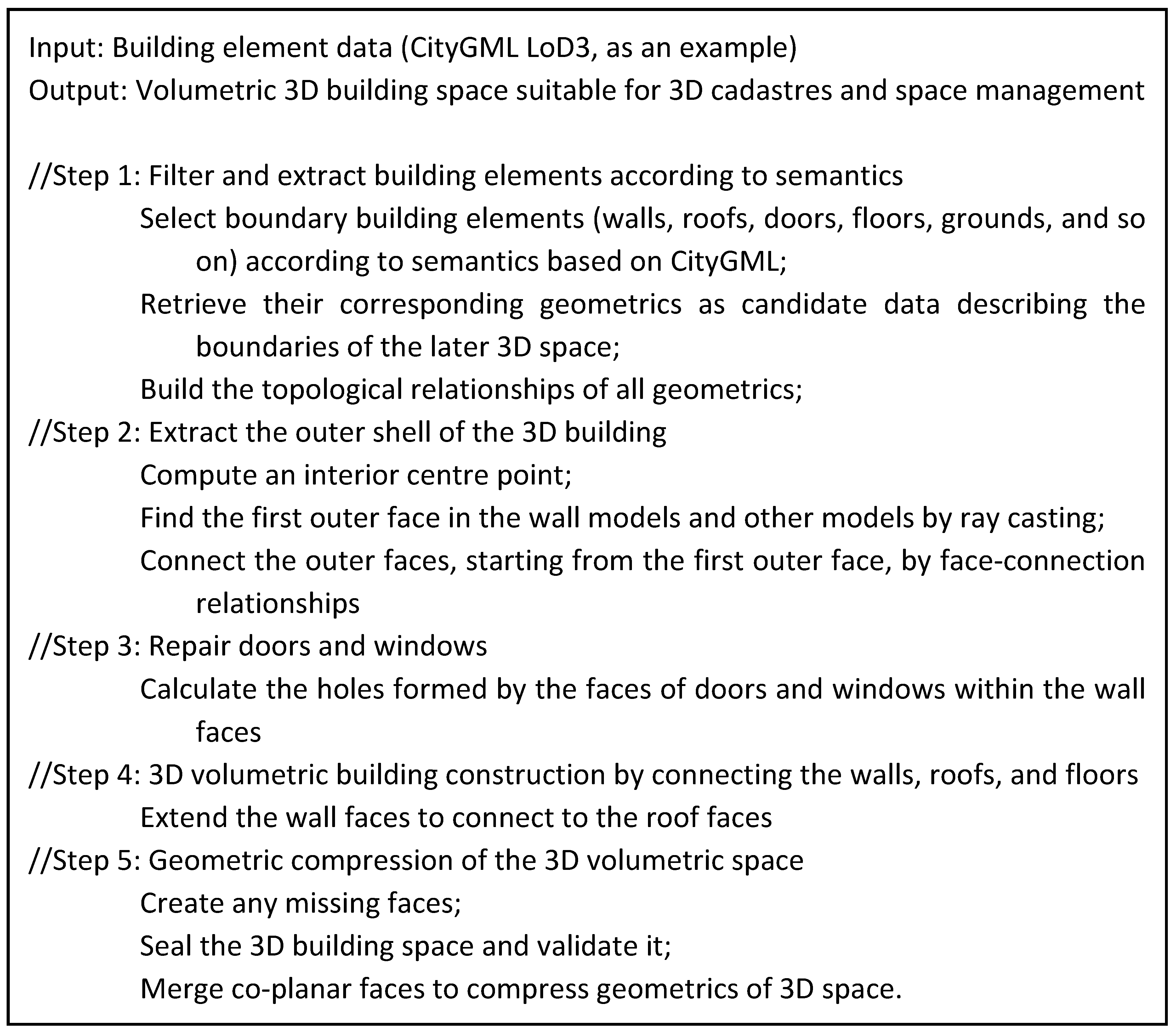
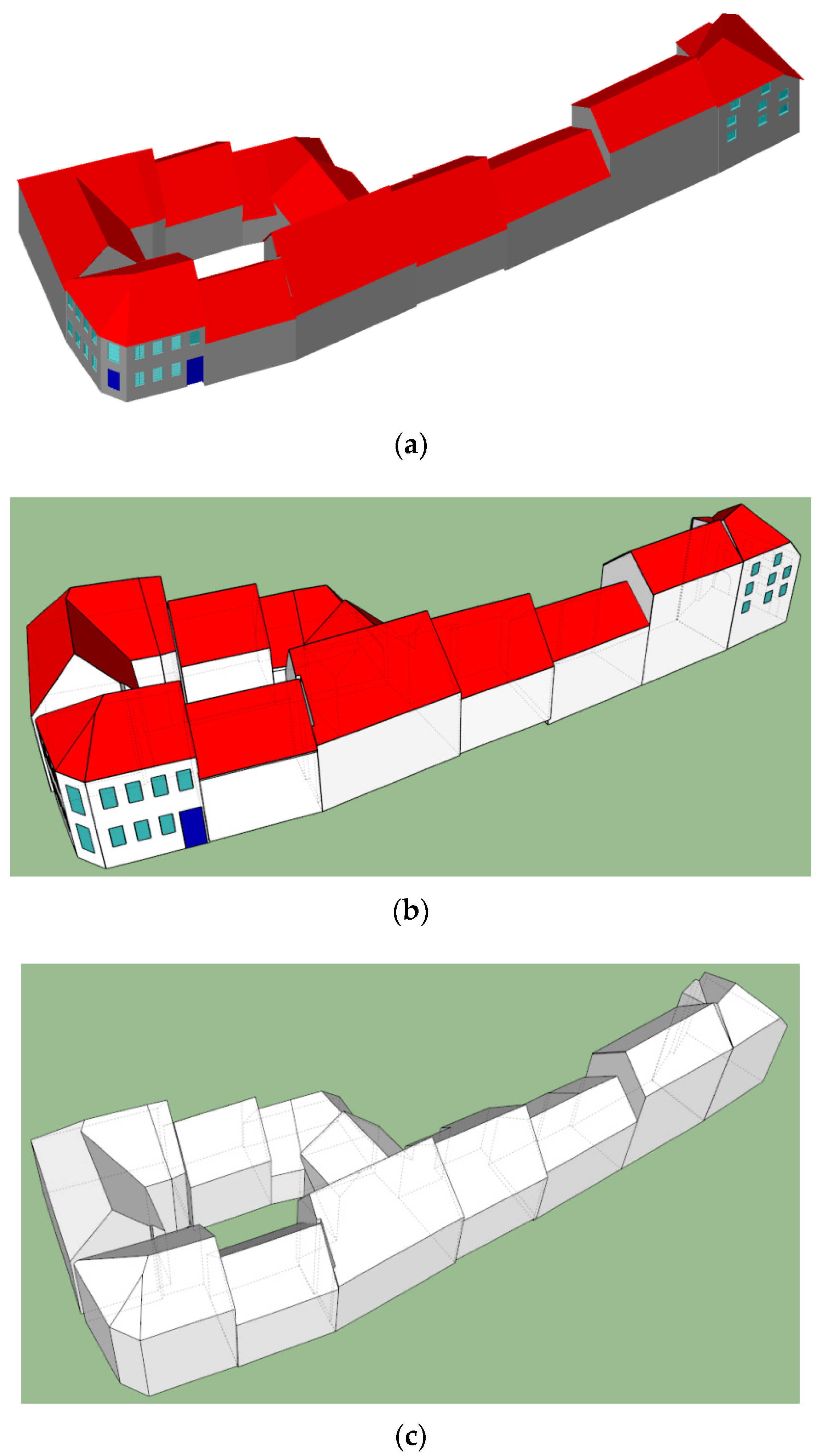
4. 3D Volumetric Construction from CityGML LoD3 and Its Simplification

For 3D cadastres, attention has been given to the 3D space where the building is located. In contrast to approximating the volume of 3D buildings using voxels [22], we propose a five-step algorithm that shifts multiple building elements to a 3D volumetric space for 3D volumetric building construction along with a geometric simplification of 3D building models. In combination with the features of the CityGML LoD3 building model, the five-step processes are carried out as follows (Figure 2): (1) filtering and deriving semantic building elements from CityGML LoD3, (2) extracting the outer shell of all the 3D faces of the boundary building elements in CityGML LoD3 models, including walls and roofs, (3) repairing the geometric faces of doors and windows attached to the wall and the ground surface, and (4) extending the faces of walls so they connect and snapping them with the roof elements to envelop and build 3D volumetric geometry to represent a 3D building space [4]. In these steps, many geometric processes such as intersecting and deleting the dangling faces are used to refine the faces that will envelop the 3D building space. The geometrics of 3D objects are compressed and simplified in step (5), and the coplanar 3D faces between walls, doors, and windows are merged and fused to reduce the data volume of the 3D geometry. This step handles the geometric processes for all unified 3D faces, regardless of their semantics (e.g., wall, door, or roof), to achieve a pure 3D simplification of shapes that best fit with the original shapes while using a different geometry.

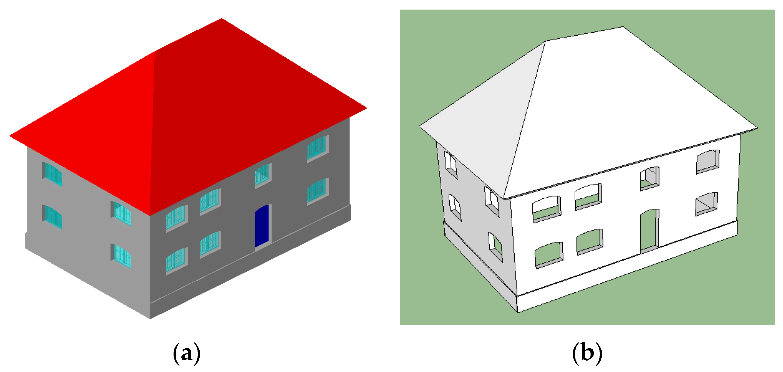
4.1. Filter and Extraction of 3D Building Elements from CityGML Data

Using the semantic information in the CityGML data, the first step of the proposed method extracts the 3D building elements, retaining their semantics in the process of 3D volumetric construction while avoiding the disadvantages of a pure geometric compression of redundant faces.
The semantic and geometric information of CityGML is consistent; therefore, the semantic information can be analysed to filter the 3D models, which facilitates later simplification. Doors and windows in CityGML LoD3 have their own attributes and geometric descriptions, and objects such as walls and roofs include information regarding their thickness. Most of these objects are formed by at least six faces, as shown in Figure 1. Generally, each building contains windows, doors, walls, and so on. Clearly, walls contain doors and windows, and a building has a consistent geometry. Based on these concepts, the semantic information for the 3D models is analysed to select the objects that can serve as candidates for volumetric construction. Details such as BuildingInstallation and openings (door or window) can be filtered out, while objects such as WallSurface, RoofSurface, and GroundSurface are retained to simplify future processing.
Because a CityGML file contains clear elements (i.e., interior and openings) that can be used to indicate doors and windows in the wall model and because the boundaries of doors and windows are consistent with the geometrics in the wall model, the semantic and geometric information of the walls, doors, and windows can be traced using only the wall model. In other words, the co-location between the wall interior/opening and the door/window can be used to simplify the data by omitting the windows and doors. For example, as shown in in Figure 3a, after filtering the door and windows semantics, the walls of the buildings are visualized as shown in Figure 3b. In Figure 3a, the doors and the windows are holes in the wall and are marked with special elements during the process before their repair, which is described in Section 4.3.

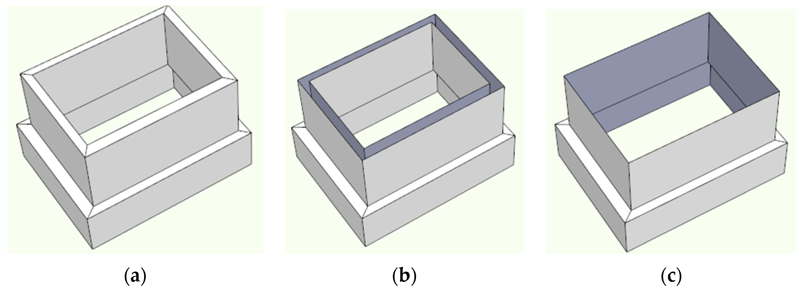
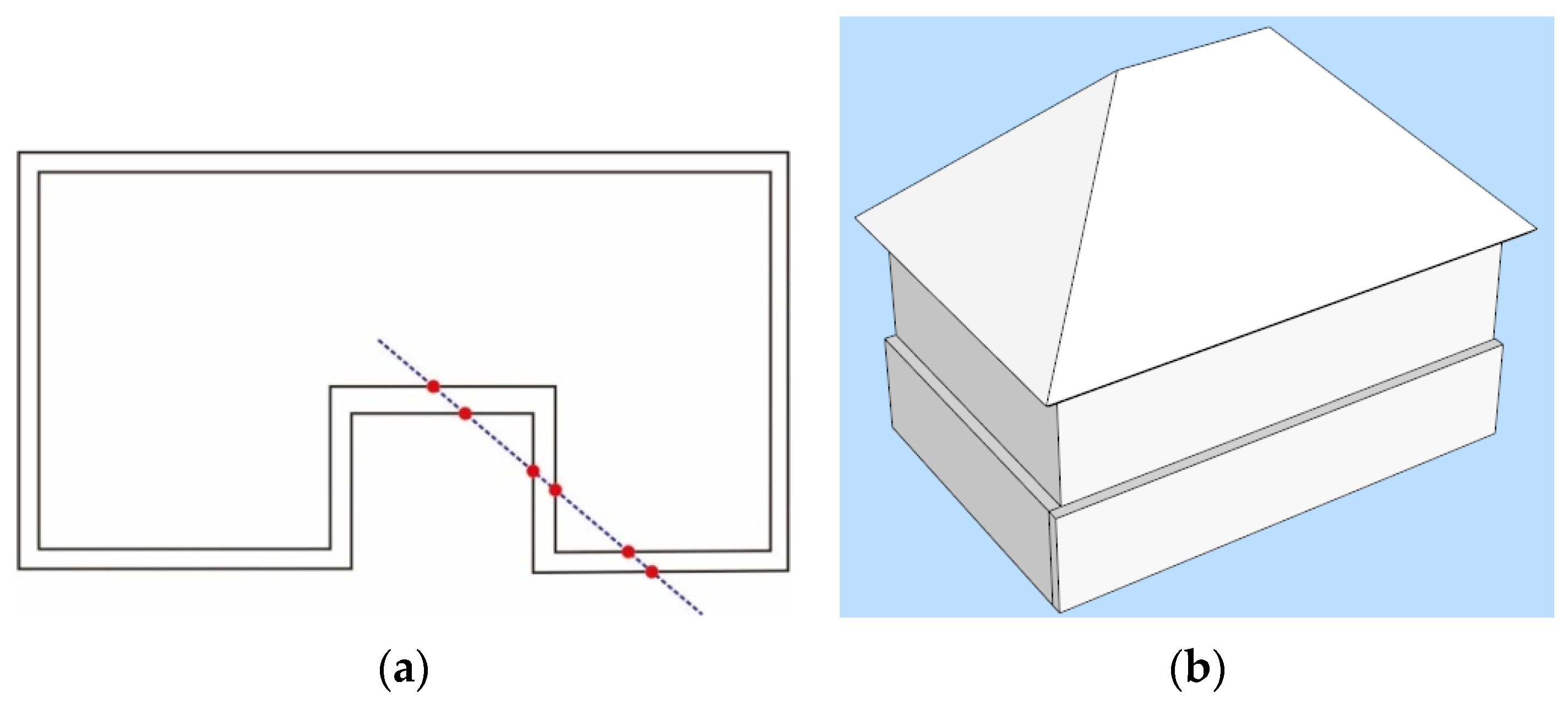
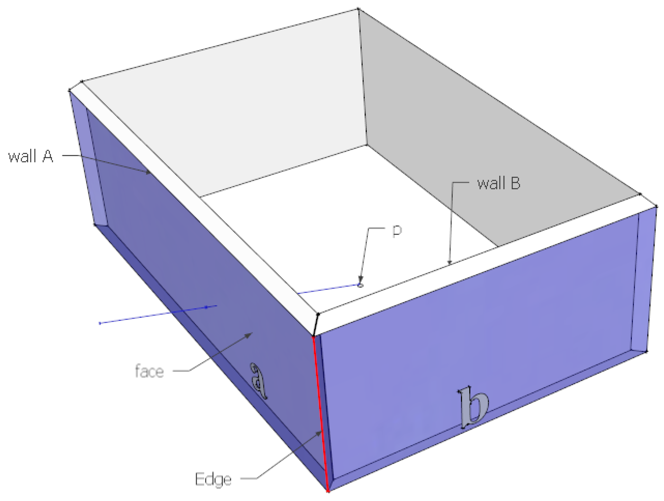
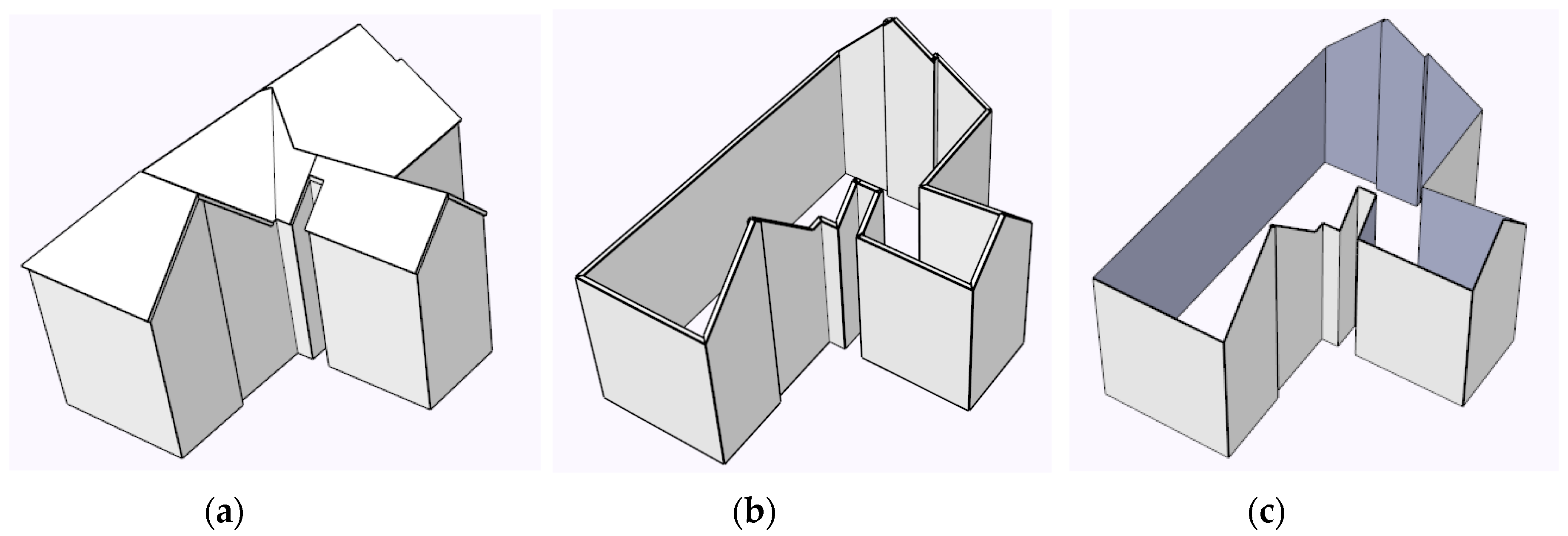
4.2. Outer Shell Extraction of the 3D Building

To construct a 3D building space, this paper aims to extract the exterior shell of a single building to represent its 3D boundary while retaining the precise locations and shapes without coordinate displacement. Most simplification methods are based on the building footprint and extrude the footprint used to create 3D models; however, these methods change the building boundaries. To extract the exterior shell of a building, the most common approaches use ray casting. However, the wall arrangements of buildings are not regular, and the intersecting plane of a ray and a wall may not be an exterior face. As shown in Figure 4a, a ray is cast from the centre of the footprint of the building onto the walls (line in Figure 4a). This ray may pass through several walls; consequently, it is difficult to determine which line (wall) is the outer wall. Furthermore, in many large buildings, walls have more than one exterior face due to the non-uniformity of walls in the vertical direction, as shown in Figure 4b. Walls adjacent to the bottom protrude more than the upper walls, and in this environment, multiple vertical walls connect the horizontal walls. Under these conditions, a normal ray-casting method cannot achieve an accurate extraction of 3D boundaries of 3D building models. In this paper, we first identify one exterior face and use it to connect other faces to reach the goal.
A building consists of walls and roofs; hence, the extraction of the external shell of a building is conducted by dividing a building into two parts, walls and roofs.
Based on the non-uniformity of the walls in the vertical direction, the walls of buildings can be divided into two types: single vertical face and multiple vertical face walls. Because no clear descriptions or definitions exist in CityGML for the spatial relationships between walls or exterior faces in 3D space, defining the interrelations between walls or exterior faces becomes important for identifying walls or exterior faces. Fan et al. [32] provided a method for extracting the outer shell by converting CityGML walls into point clouds to obtain the centroid of the building and to check each face of the walls and the windows with ray casting. In contrast to Fan’s outer wall extraction via point clouds, this paper first uses footprints to identify the centre point and to cast a ray onto the wall to locate one random exterior face of the wall. Then, this wall is used as the starting face to search for other exterior faces, maintain their shapes, and connect them. This paper uses different processing methods based on the properties of two types of wall models.
In CityGML, walls are organized separately. Each wall model (i.e., WallSurface) is formed by multiple faces. The adjacency of walls can be determined by whether they share a face (whether an xlink is used in CityGML) or have the same geometrics of several coordinates between the walls. Then, the topological neighbour relationship can be used to check the connection between different wall models. This paper uses a depth-first search method to extract the outer exterior faces of all walls as follows:
(1) A ray is directed from the centre point to intersect one wall model, and the face in WallSurface with the longest distance from the centre point is the first exterior face of the walls of the building. As shown in Figure 5, from this intersection, wall model A is selected, and the wall face a is determined to be the first exterior face for the outer shell.
(2) Other wall models are determined using neighbour topology and the selected wall model, thus, another face is selected. As shown in Figure 5, wall model A and wall model B have a topological neighbour relationship because they share the face marked in red. Because wall model A was selected, wall model B is triggered as a candidate, and its geometric faces were tested. Because face b in wall B is topologically connected with the first exterior face a in wall A, face b is selected as the second exterior face of the outer shell of the walls.
(3) This propagation of topological connection and neighbour face selection results in obtaining all the exterior faces of the wall models. An example of a 3D building model is shown in Figure 6a, and all the walls are depicted in Figure 6b. After extraction, the outer shells of the walls are obtained, as shown in Figure 6c.
This method is particularly important for walls with multiple vertical faces. A wall with multiple vertical faces may have many exterior faces on one side. Moreover, two or more vertical walls may be connected by other faces in different directions. For the complex walls shown in Figure 7a, there are eight wall models, each of which is represented by a multi-surface. The method identifies the exterior vertical faces of the walls and the connecting faces between them in either the horizontal or vertical direction through a face-connection process [4], which is vital for topological connection and volumetric construction because of the need for a closed and watertight 3D geometry. In contrast with a monotonous vertical face wall model, more than one face is selected as the exterior shell from each wall model when using MultiSurface. The exterior faces of all walls are illustrated in Figure 7b,c.
The roof model is similar to the wall model with either multiple RoofSurfaces or one RoofSurface. More importantly, the method also successfully extracts the outer roof faces from the roof models, regardless of whether a building has one or more roof models. Figure 8 shows an example of the exterior faces of the roof models. A complex roof model is shown in Figure 8a, while Figure 8b shows the detailed shape of a roof corner. These shapes can also be handled correctly, as shown in Figure 8c.

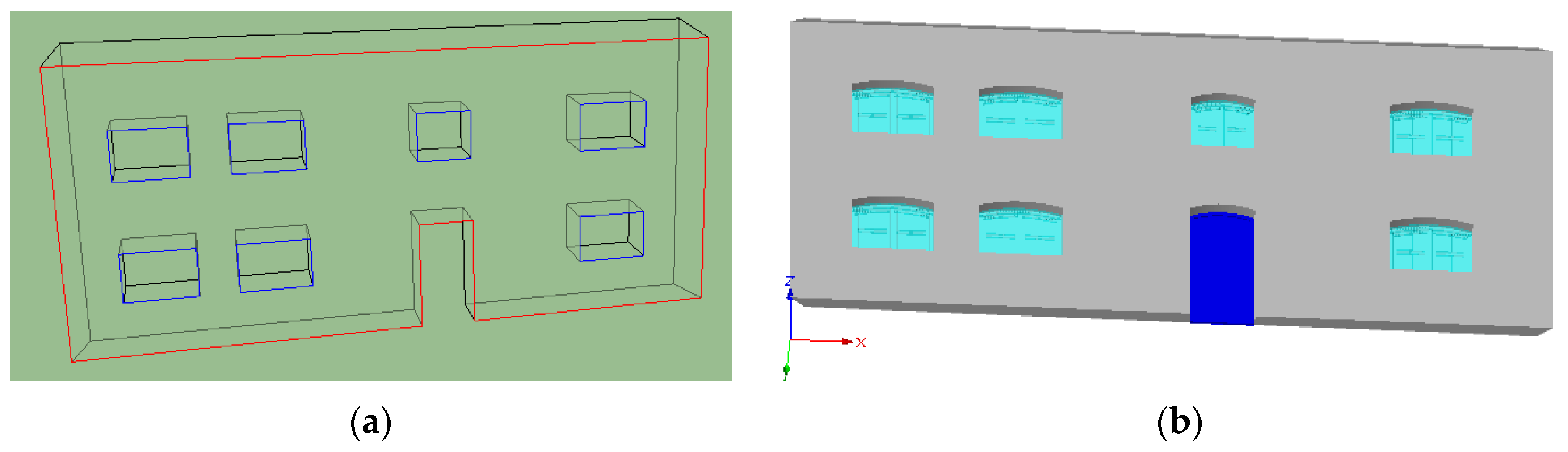
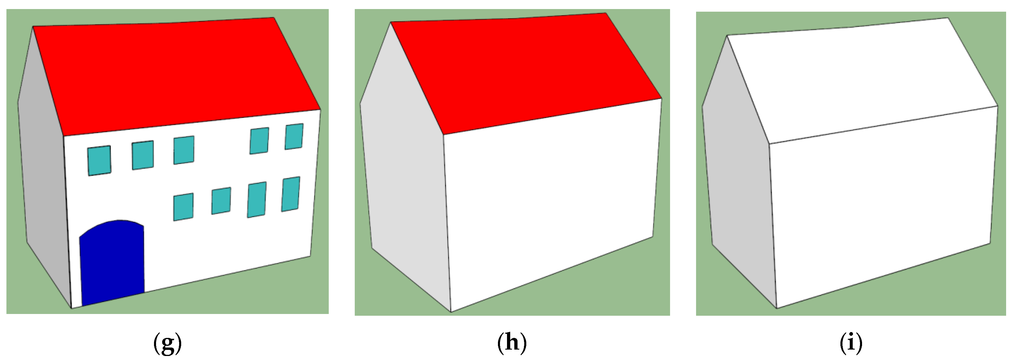
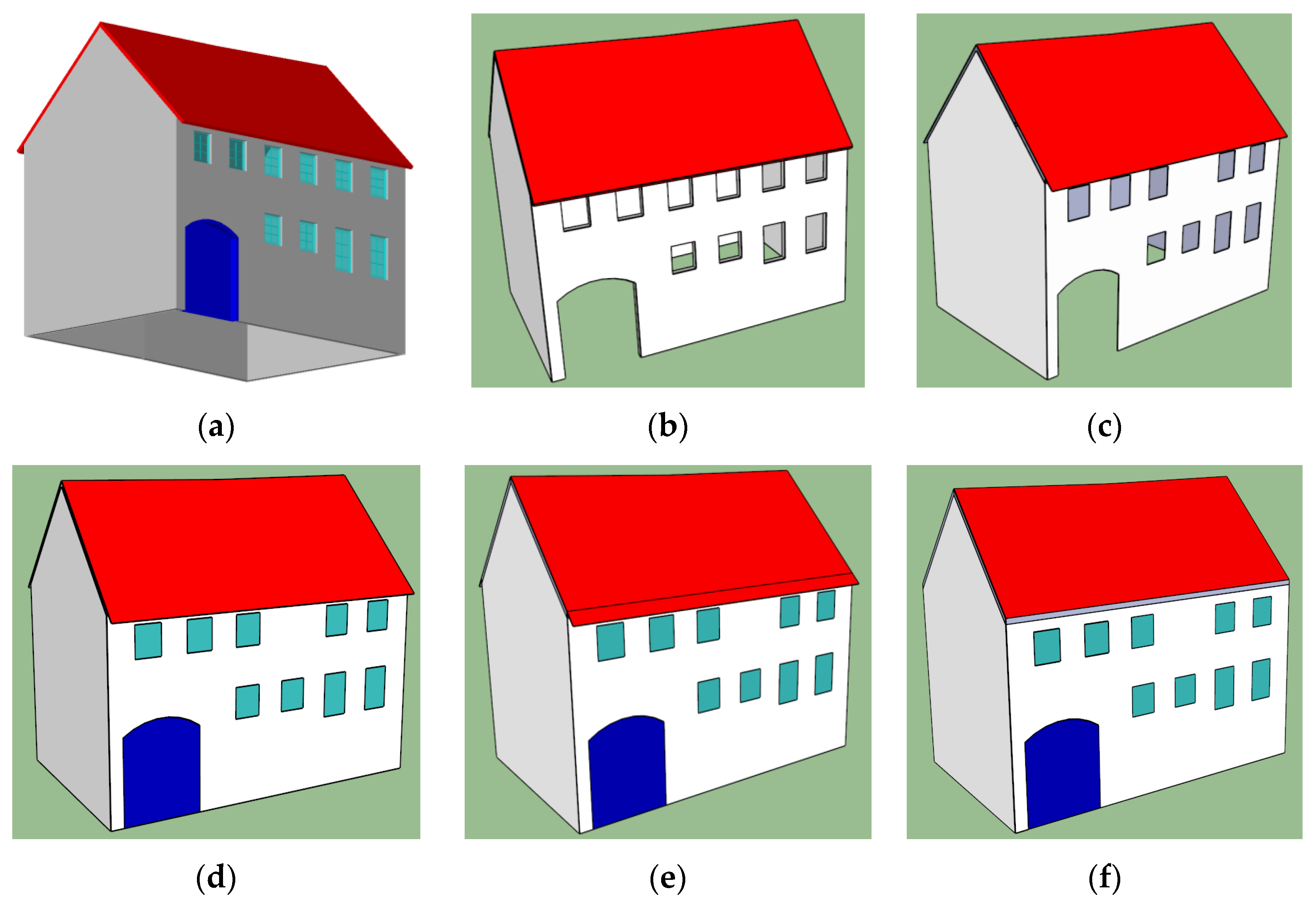
4.3. Repairing the Doors and the Windows

Based on the semantic analysis results, only a portion of the building features in the CityGML file are involved in constructing the 3D volumetric object, as described in the feature filter in Section 4.1. Based on the CityGML data organization, the walls include holes for doors or windows. Notably, one 3D through-hole was formed by four or more faces in the model in which windows were omitted. Therefore, faces forming holes must be handled, and wall faces containing holes should be filled to make the walls an integral object.
Here, we provide details regarding window processing. Windows are mainly geometrical holes in walls. For walls that contain windows, the wall faces include two elements: <gml:exterior> to mark the outer boundaries of the wall surface and <gml:interior> to mark the holes in the surface. The red lines in Figure 1 are the outer boundaries of the wall and the blue lines are the interior boundaries (i.e., the outer boundaries of the windows). As described in Section 4.2, the exterior faces of the wall models have already been extracted and the 3D through-hole becomes a 2D hole on the wall plane. To repair holes that resulted from deleting windows, the deletion of excessive faces due to the placement of windows is required. Excessive faces can be deleted using <gml:interior> along with the adjacent relationships between the faces forming holes. Next, the wall surface containing holes can be filled with a coplanar 2D face to repair the holes in the walls or roofs caused by the inclusion of windows. During processing, all shape coordinates are maintained to show the original precise locations of the walls and door, and their corresponding semantics are recorded.

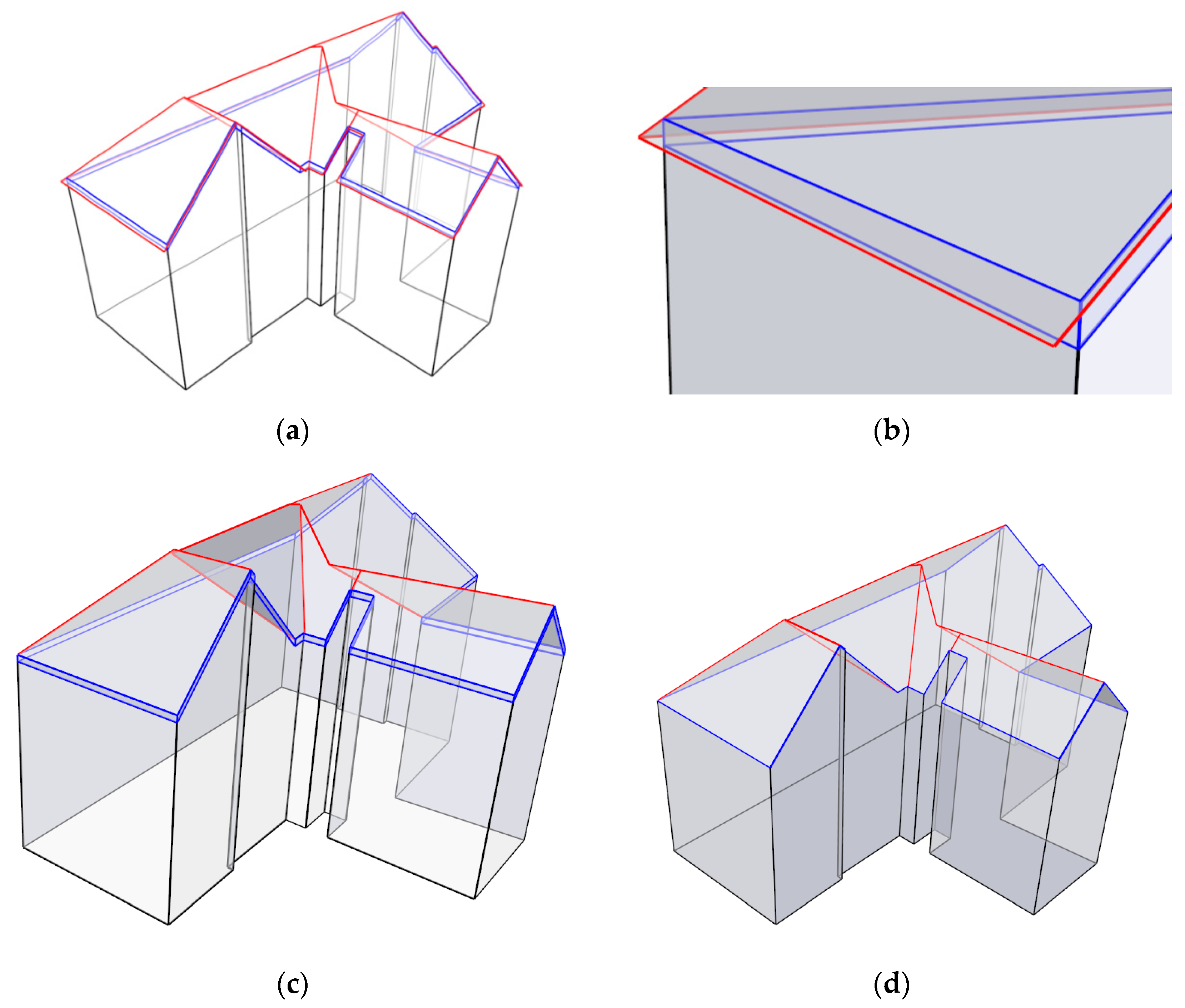
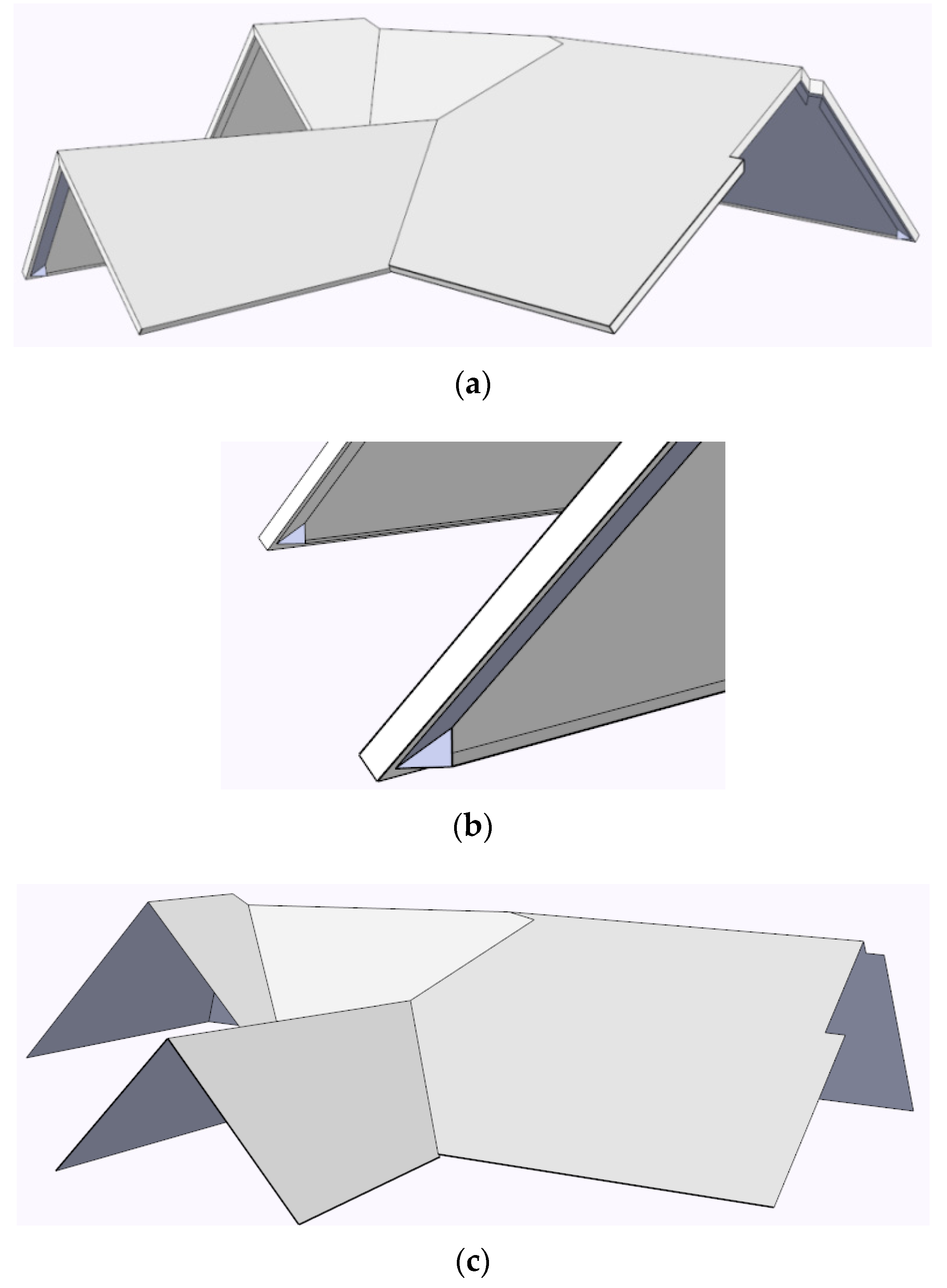
4.4. 3D Volumetric Building Construction by Connecting the Walls, Roofs, and Floors

After extracting the exterior wall faces and roof faces, 3D volumetric construction of 3D buildings is considered by asking the following question: how can the 3D volumetric space be closed? To envelop the building in a 3D volume, the exterior faces of the walls, roof, and ground must be tailored. The three following steps are performed to complete this task: (1) filling the ground, (2) extending the walls to meet the roof, and (3) validating the resulting 3D volumetric object.
To fill in the ground, the upper face that connects with the wall is selected if a ground floor exists. Otherwise, a new face is added to fill the bottom of the buildings using the footprint of the walls.
Using the extracted exterior walls and roofs of the building, we can identify gaps between the roofs and walls. Therefore, a connecting and snapping process between the walls and the roof is required. In contrast with building reconstruction and the direct extrusion of building footprints, to maintain the detailed shape of the building, the walls and roofs are connected by extending the existing exterior walls with the windows and doors inside. In the case of a single vertical face, all the exterior walls are directly extended. In the case of multiple vertical faces, the exterior walls adjacent to the roofs are extended, as shown in Figure 9a. As shown in Figure 9b, the roof faces are represented by red lines and the wall faces are extended, intersecting with a roof face (represented by blue lines). As the results of the extension and intersection, the roof faces are divided into two types. One type of roof face fits the walls exactly and sits directly on top of the building, while the other type of face has an eave that extends slightly beyond the building body. Because the eaves do not impact building volume, they are deleted, as shown in Figure 9c. Then, because the wall and its extension are consistent they are united and fused together, as shown in Figure 9d.
At this point, all the bounding faces of the building have been created. All the pertinent geometric shapes of the walls, doors, roofs, and ground have been used to construct a 3D volumetric building, and all the faces have been connected and glued together using neighbour face connection [4,33] to envelop a 3D volume. Now, we can validate the created 3D geometry using the rules described in [34,35,36,37].
During the processes described above, we maintained the semantics of CityGML objects along with their geometrics. Thus, the walls, roofs, grounds, doors, and windows retain their locations in the 3D volumetric building, as shown in the detailed cases presented in Section 5.
3D volumetric models with semantic or labelled windows, doors, and roofs can help users understand the semantics and locations of such elements, while simplified models that do not include these elements can minimize the amount of data needed while retaining the 3D volumetric geometry of a building.

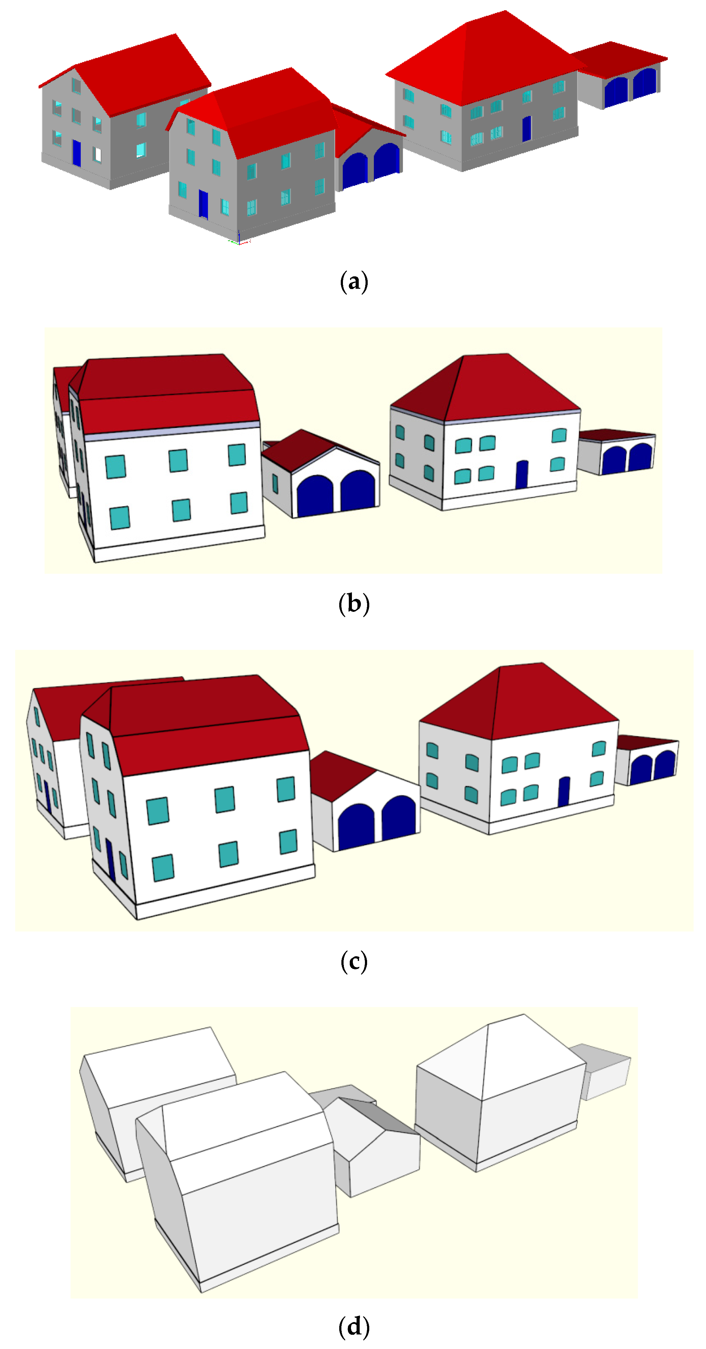
4.5. Geometric Compression of the 3D Volumetric Space

A 3D volumetric building can be constructed using the above procedures to obtain the 3D volumetric space of the building. Building elements (i.e., walls, roofs, doors, and windows) in CityGML LoD3 with thickness were extracted based on the outer shell while retaining their geometrics to show their locations in the building in the previous four steps. The last step of our method is to simplify the 3D volumetric building and convert it into a pure 3D object with a pure semantic description of “building” that can be treated as a 3D parcel in a 3D cadastre. This simplification is performed by merging the coplanar faces of the CityGML LoD3 objects without changing the boundaries and shape of the building. There are two types of coplanar situations: (1) the same object types are coplanar (e.g., several walls compose one side wall) and (2) different object types are coplanar (e.g., a wall contains a door and windows). All the coplanar faces can be simplified by neglecting the semantics of the building elements. Because “the small gap faces” are created by wall extension, they belong semantically to the wall. Therefore, these faces are merged with the original wall faces to form a solid wall face on one side, as shown in Figure 10g,h. After this step, no parts of the building will have a semantic distinction, but the 3D building will be unified into a 3D closed space described by a 3D solid. Furthermore, this model can be converted and restored in CityGML LoD2 using solid geometry.

5. Implementation and Experimental Results

Based on the method described above for constructing and simplifying a 3D volumetric building, an implementation was performed using the Google SketchUp platform and the Ruby development language. The platform was a PC with an Intel(R) Core i3 3.2 GHz CPU and 4.00 GB of RAM running the Microsoft Windows 7 Professional x64 operating system. The authors implemented a 3D space shift for automatic 3D volumetric construction from LoD3 building elements, retaining the locations of doors and windows and saving the models in the form of SketchUp and CityGML files.
For this paper, three cases of LoD3 data (downloaded from the official CityGML website) were used to verify the feasibility of the proposed method. The first case is an individual building that included one door, 10 windows, five walls, and three roofs, totalling 910 faces, as shown in Figure 10a, visualized using FZK software. After importing the case into SketchUp, the door and window models were filtered out based on their semantic information (Figure 10b). Next, the exterior faces of the wall and roof models were extracted (Figure 10c), and the faces of the ground, door, and windows were repaired (Figure 10d). The wall faces were extended to intersect with the roof faces (Figure 10e), and the eaves were deleted (Figure 10f). Finally, a 3D volumetric building was generated (Figure 10g). To further compress the geometry of the 3D building, the coplanar faces were merged into one face (Figure 10h) to obtain the pure solid form of the building, as shown in Figure 10i. As shown by the results of the 3D volumetric building construction, the 3D building with refined geometric locations of doors, windows, roofs, and the ground included 26 faces (Figure 10g). During these procedures, the locations and shapes of the windows, doors, and walls were maintained precisely, without changes. After simplifying the coplanar faces, the resulting pure 3D building space (Figure 10i) included six faces. During all these procedures, the outer shape of the building—or, more precisely, the 3D space of the 3D building—is stable, which is vital for the computational analysis of 3D space management in 3D cadastres and other applications (e.g., heat estimation).
To further test the methods described in this paper, two more complex building sets were selected, as shown in Figure 11 and Figure 12. Six independent buildings were selected from the CityGML LoD3 data (Figure 11a), of which three have multiple vertical walls. The intermediate steps of object filtering and 3D volumetric building construction are shown in Figure 11b. The 3D volumetric building construction after four of the steps involved in our method is depicted in Figure 11c, and the final solid model is illustrated in Figure 11d.
Figure 12 shows a case study of adjacent buildings that differ from the independent buildings in Figure 11. In the actual data, some of the buildings have doors and windows. The method described here can successfully extract the outer shell of a building and maintain the neighbour relationship between buildings without changing the boundaries of those buildings. The 3D volumetric buildings with precise door and window locations are shown in Figure 12b, and the simplified 3D volumetric buildings are shown in Figure 12c.
The different cases in Figure 10, Figure 11, and Figure 12 illustrate how precise 3D building space construction is performed from multiple building elements in CityGML LoD3 using the proposed method, which successfully transforms multiple building elements into 3D volumes. To consider data storage requirements, we compare the results before and after the 3D volumetric construction. Table 1 and Table 2 list the CityGML object statistics of Cases 2 and 3, respectively. A total of 19,365 faces for Case 2 and 3366 faces in Case 3 were used in the original CityGML LoD3 data; however, after applying the proposed method, the 3D volumetric buildings required only 188 and 167 faces for Cases 2 and 3, respectively, and—after simplification—the final unified 3D volumetric buildings required only 66 faces for Case 2 and 132 faces for Case 3. During the procedures, the amount of data was significantly reduced compared with the initial input data, while the locations of doors and windows were maintained to retain an excellent visualization effect. This data reduction occurred because vertical walls normally co-exist, contain doors and windows, and are generally represented by one face for each side, except when multiple facades occur on one side.
To meet the visualization requirements, the resulting 3D volumetric buildings can be stored as solid models that represent the objects in CityGML LoD2 or can be saved as X3D, VRML, or KML files.

6. Discussion and Conclusions

From the viewpoint of obtaining the entire 3D building space for 3D cadastres, this paper integrates a method to conduct the 3D volumetric construction needed for the 3D cadastral application with cartographic visualization concerning the geometric compression. First, the paper reorganizes the geometric data of the building elements to create a 3D volumetric space of the entire building. From a cadastral viewpoint, a 3D parcel should have a precise 3D volumetric space with homogeneous rights. When it is implemented into houses and buildings, a 3D parcel should be the 3D volumetric space of the building; however, current BIM or CityGML data, from an entity viewpoint, describe the components and element of the building, but not its volume. This logical change of space for 3D cadastral space and 3D space management is the difference in the concept presented in this paper compared to previous 3D visualization applications. Second, the resulting 3D buildings have the simplest possible geometrics without changing the locations and coordinates of the outer boundary lines and faces of the buildings. The boundaries of the 3D cadastral space not only describe the geometric/geographic locations but also carry legal meanings concerning the legal rights (e.g., ownership, tenure) of space occupation. Consequently, during the construction and simplification of the 3D building space, the proposed method maintains precise building boundaries while simultaneously compressing the building geometric data, as shown in the experiments.
Increasingly, 3D city models such as CityGML and IFC are accepted as standard data input by an increasing number of surveying offices; however, 3D volumetric representations of buildings are urgently needed not only for spatial analysis and calculation but also for 3D cadastral and property space management. This paper proposes a precise 3D space shift to construct a simplified true 3D building geometry from the multiple building elements in 3D CityGML LoD3 data without making any location changes or displacing the boundaries of the 3D building space. This approach uses 3D boundary extractions and face connections to represent 3D volumetric buildings. The five-step algorithm is quite effective for two reasons. On one hand, the 3D volumetric space of 3D buildings is acquired and precisely preserved to maintain the volume of the 3D geometry originally expressed by multiple building elements. This simplified model provides better support for fields such as 3D cadastre management and can also be used to process multiple adjacent buildings. On the other hand, it also simplifies the construction of 3D volumetric buildings and, thus, achieves a high compression factor of the geometric data, complying with the criteria of 3D geometry in ISO 19107 and GML. The results could effectively be used by urban municipalities to manage 3D property spaces and support 3D space planning.

Acknowledgments

The work is partly supported by the National Natural Science Foundation of China under Grants 41371369, 41671381, and 41531177, and is partly supported by Open Project Fund of Key Laboratory of Urban Land Resources Monitoring and Simulation, Ministry of Land and Resources. The authors thank the associate editor and the referees for their helpful comments.

Author Contributions

Shen Ying and Renzhong Guo conceived the main idea of the study and designed the experiments. Jie Yang and Fengzan Jin performed the experiments together. Biao He and Zhigang Zhao analysed the data. Shen Ying, Renzhong Guo and Jie Yang wrote the first version of the paper and all the authors improved the versions.

Conflicts of Interest

The authors declare that there are no conflicts of interest.

References

  1. Cappelle, C.; El Najjar, M.E.; Charpillet, F.; Pomorski, D. Virtual 3D city model for navigation in urban areas. J. Intell. Robotic Syst. 2012, 66, 377–399. [Google Scholar] [CrossRef]
  2. Van Oosterom, P.; Stoter, J.; Ploeger, H.; Thompson, R.; Karki, S. World-wide inventory of the status of 3D cadastres in 2010 and expectations for 2014. In Proceedings of the FIG Working Week 2011 “Bridging the Gap between Cultures” & 6th National Congress of ONIGT, Marrakech, Morocco, 18–22 May 2011; ONIGT: Rabat, Morocco, 2011; pp. 117–122. [Google Scholar]
  3. Ying, S.; Li, L.; Guo, R. Building 3D cadastral system based on 2D survey plans with SketchUp. Geo-Spat. Inf. Sci. 2011, 14, 129–136. [Google Scholar] [CrossRef]
  4. Ying, S.; Guo, R.; Li, L.; Van Oosterom, P.; Stoter, J. Construction of 3D volumetric objects for a 3D cadastral system. Trans. GIS 2015, 19, 758–779. [Google Scholar] [CrossRef]
  5. D’Silva, M.G.; Speckmann, B.; Westenberg, M.A.; van Hee, K.M. A feasibility study on CityGML for cadastral purposes. Master’s Thesis, Technische Universiteit Eindhoven, Eindhoven, The Netherlands, 2009. [Google Scholar]
  6. Biljecki, F.; Ledoux, H.; Stoter, J. Error propagation in the computation of volumes in 3D city models with the Monte Carlo method. ISPRS Ann. Photogramm. Remote Sens. Spat. Inf. Sci. 2014, 2, 31–39. [Google Scholar] [CrossRef]
  7. Carrión, D.; Lorenz, A.; Kolbe, T.H. Estimation of the energetic rehabilitation state of buildings for the city of Berlin using a 3D city model represented in CityGML. ISPRS Int. Arch. Photogramm. Remote Sensing Spat. Inf. Sci. 2010, 38, 31–35. [Google Scholar]
  8. Krüger, A.; Kolbe, T.H. Building analysis for urban energy planning using key indicators on virtual 3D city models—The energy atlas of Berlin. In Proceedings of the ISPRS International Archives of the Photogrammetry, Remote Sensing and Spatial Information Sciences, Melbourne, Australia, 25 August–1 September 2012; Volume 39, pp. 145–150.
  9. Zlatanova, S.; Rahman, A.; Shi, W. Topological models and frameworks for 3D spatial objects. Comput. Geosci. 2004, 30, 419–428. [Google Scholar] [CrossRef] [Green Version]
  10. Biljecki, F.; Ledoux, H.; Stoter, J.; Zhao, J. Formalisation of the level of detail in 3D city modelling. Comput. Environ. Urban Syst. 2014, 48, 1–15. [Google Scholar] [CrossRef]
  11. Geiger, A.; Benner, J.; Haefele, K. Generalization of 3D IFC building models. In 3D Geoinformation Science, Lecture Notes in Geoinformation and Cartography; Breunig, M., AI-Doori, M., Butwilowski, E., Kuper, P., Benner, J., Haefele, K., Eds.; Springer International Publishing: Cham, Switzerland, 2015; pp. 19–35. [Google Scholar]
  12. Fan, H.; Meng, L. A three-step approach of simplifying 3D buildings modeled by CityGML. Int. J. Geogr. Inf. Sci. 2012, 26, 1091–1107. [Google Scholar] [CrossRef]
  13. He, S.; Moreau, G.; Martin, J.Y. Footprint-based 3D generalization of building groups for virtual city visualization. In Proceedings of the GEO Processing 2012: The Fourth International Conference on Advanced Geographic Information Systems, Applications, and Services, Valencia, Spain, 30 January–4 February 2012; pp. 177–182.
  14. Buchin, K.; Meulemans, W.; Speckmann, B. A new method for subdivision simplification with applications to urban-area generalization. In Proceedings of the 19th ACM SIGSPATIAL International Conference on Advances in Geographic Information Systems, Chicago, IL, USA, 1–4 November 2011; pp. 261–270.
  15. Mao, B.; Ban, Y.; Harrie, L. A multiple representation data structure for dynamic visualisation of generalised 3D city models. ISPRS J. Photogramm. Remote Sens. 2011, 66, 198–208. [Google Scholar] [CrossRef]
  16. Baig, S.U.; Rahman, A.A. A three-step strategy for generalization of 3D building models based on CityGML specifications. GeoJournal 2013, 78, 1013–1020. [Google Scholar] [CrossRef]
  17. Kada, M. Automatic generalization of 3D building models. ISPRS Int. Arch. Photogramm. Remote Sens. Spat. Inf. Sci. 2002, 34, 243–248. [Google Scholar]
  18. Kada, M. Scale-dependent simplification of 3D building models based on cell decomposition and primitive instancing. In Spatial Information Theory; Winter, S., Duckham, M., Kulik, L., Kuipers, B., Eds.; Springer Verlag: Berlin, Germany, 2007; pp. 222–237. [Google Scholar]
  19. Anders, K.-H. Level of detail generation of 3D building groups by aggregation and typification. In Proceedings of the XXII International Cartographic Conference, La Coruna, Spain, 9–16 August 2005.
  20. Mayer, H. Scale-spaces for generalization of 3D buildings. Int. J. Geogr. Inf. Sci. 2005, 19, 975–997. [Google Scholar] [CrossRef]
  21. Mao, B.; Harrie, L. Methodology for the efficient progressive distribution and visualization of 3D building objects. ISPRS Int. J. Geo-Inf. 2016, 5, 185. [Google Scholar] [CrossRef]
  22. Steuer, H.; Machl, T.; Sindram, M.; Liebel, L.; Kolbe, T. Voluminator—Approximating the volume of 3D buildings to overcome topological errors. In AGILE 2015; Bacao, F., Santos, M.Y., Painho, M., Eds.; Springer International Publishing: Cham, Switzerland, 2015; pp. 343–362. [Google Scholar]
  23. Thiemann, F. Generalization of 3D building data. ISPRS Int. Arch. Photogramm. Remote Sensing Spat. Inform. Sci. 2002, 34, 286–290. [Google Scholar]
  24. Thiemann, F.; Sester, M. Segmentation of buildings for 3D-generalisation. In Proceedings of the 7th ICA Workshop on Generalisation and Multiple Representation, Leicester, UK, 20–21 August 2004.
  25. Thiemann, F.; Sester, M. 3D-symbolization using adaptive templates. In Proceedings of the ISPRS Technical Commission II Symposium, Vienna, Austria, 12–14 July 2006; pp. 49–54.
  26. Forberg, A. Generalization of 3D building data based on a scale-space approach. In Proceedings of the ISPRS 20th Congress of the IRPRS, Istanbul, Turkey, 12–23 July 2004; Volume 35, pp. 194–199.
  27. Forberg, A. Generalization of 3D building data based on a scale-space approach. ISPRS J. Photogramm. Remote Sens. 2007, 62, 104–111. [Google Scholar] [CrossRef]
  28. Van Oosterom, P. Research and development in 3D cadastres. Comput. Environ. Urban Syst. 2013, 40, 1–6. [Google Scholar] [CrossRef]
  29. Gröger, G.; Kolbe, T.H.; Czerwinski, A.; Nagel, C. OGC City Geography Markup Language (CityGML) Encoding Standard; Open Geospatial Consortium: Wayland, MA, USA, USA, 2012. [Google Scholar]
  30. Gröger, G.; Plümer, L. CityGML—Interoperable semantic 3D city models. ISPRS J. Photogramm. Remote Sens. 2012, 71, 12–33. [Google Scholar] [CrossRef]
  31. Kolbe, T.H. BIM, CityGML and related standardization. In Proceedings of the 2012 Digital Landscape Architecture Conference, Bernburg/Dessau, Germany, 31 May–1 June 2012.
  32. Fan, H.; Meng, L.; Jahnke, M. Generalization of 3D buildings modelled by CityGML. In Advances in GIScience; Sester, M., Bernard, L., Paelke, V., Eds.; Springer Verlag: Berlin, Germany, 2009; pp. 387–405. [Google Scholar]
  33. Diakite, A.; Damiand, G.; Van Maercke, D. Topological reconstruction of complex 3D buildings and automatic extraction of levels of detail. In Eurographics Workshop on Urban Data Modelling and Visualiz; Besuievsky, G., Tourre, V., Eds.; Eurographics Association: Strasbourg, France, 2014; pp. 25–30. [Google Scholar]
  34. Jin, F.; Ying, S.; Li, L.; Guo, R. Validation rules and repairing true 3D solids. Geomat. Inform. Sci. Wuhan Univ. 2015, 40, 258–263. [Google Scholar]
  35. Karki, S.; Thompson, R.; McDougall, K. Data validation in a 3D cadastre. In Developments in 3D GeoInformation Sciences; Neutens, T., Maeyer, P., Eds.; Springer: Berlin Heidelberg, Germany, 2010; pp. 92–122. [Google Scholar]
  36. Alam, N.; Wagner, D.; Wewetzer, M.; Von Falkenhausen, J.; Coors, V.; Pries, M. Towards automatic validation and healing of CityGML models for geometric and semantic consistency. ISPRS Int. Arch. Photogramm. Remote Sens. Spat. Inform. Sci. 2013. [Google Scholar] [CrossRef]
  37. Wagner, D.; Wewetzer, M.; Bogdahn, J.; Alam, N.; Pries, M.; Coors, V. Geometric semantical consistency validation of CityGML models. In Progress and New Trends in 3D GeoInformation Sciences; Springer: Berlin, Germany, 2013; pp. 171–192. [Google Scholar]
Figure 1. Wall with door and windows in City Geography Markup Language (CityGML) LoD3: (a) geometric descriptions; (b) visualization of building elements.
Ijgi 06 00017 g001
Figure 2. Workflow of 3D volumetric object construction and simplification for CityGML data.
Ijgi 06 00017 g002
Figure 3. Original building (a) and after the extraction of geometric shapes with a semantic filter (b).
Ijgi 06 00017 g003
Figure 4. Schematic diagram of a building: (a) the ray intersects multiple lines (walls); (b) building with multiple vertical surfaces with connected horizontal surfaces.
Ijgi 06 00017 g004
Figure 5. Faces connecting the WallSurface when extracting the exterior faces of the walls.
Ijgi 06 00017 g005
Figure 6. Exterior face extraction of the walls: (a) original data; (b) all wall models; (c) exterior faces of the outer shell.
Ijgi 06 00017 g006
Figure 7. Extraction of the exterior wall faces from multiple vertical faces: (a) original data; (b) separation of the exterior and interior faces; and (c) extraction of the exterior wall faces.
Ijgi 06 00017 g007
Figure 8. Extraction of the exterior roof faces from multiple vertical faces: (a) original data; (b) detailed complex data of the roof model; and (c) extraction of the exterior wall faces in different views.
Ijgi 06 00017 g008
Figure 9. Extending the walls and connecting them with the roof: (a) extending the wall faces; (b) details of the intersection between the wall face and the roof face; (c) deleting the eaves; and (d) merging the gapped faces with the original wall faces.
Ijgi 06 00017 g009
Figure 10. 3D volumetric construction of an individual building and its simplification: (a) source data (visualized using FZK software); (b) building model with filtered doors and windows (visualized in SketchUp); (c) building model with exterior wall faces; (d) building model with exterior roof faces; (e) building model with the door, windows, and ground repaired; (f) extending the walls; (g) deleting the eaves and 3D volumetric building construction; (h) 3D volumetric building with coplanar face simplification; and (i) a unified 3D building.
Ijgi 06 00017 g010aIjgi 06 00017 g010b
Figure 11. The 3D volumetric construction of separate buildings: (a) source data (visualized by FZK software); (b) building model with full bounding faces of doors, windows, and grounds and wall extensions; (c) 3D volumetric buildings with semantics; and (d) unified 3D volumetric buildings.
Ijgi 06 00017 g011
Figure 12. 3D volumetric construction of adjacent buildings: (a) source data (visualized by FZK software); (b) 3D volumetric buildings with semantics; (c) unified 3D volumetric buildings.
Ijgi 06 00017 g012
Table 1. Statistics of the objects in Case 2.
ItemInputOutput
Number of Buildings66
Number of Walls36/
Number of Roofs16/
Number of Ground Surfaces0/
Number of Doors8/
Number of Windows75/
Number of Faces1936566
Table 2. Statistics of the objects in Case 3.
ItemInputOutput
Number of Buildings1010
Number of Walls65/
Number of Roofs34/
Number of Ground Surfaces0/
Number of Doors8/
Number of Windows34/
Number of Faces3366132

