A Toolbox for the Analysis of the Grasp Stability of Underactuated Fingers †


Abstract
:
1. Introduction
2. General Static Model
- is the input torque vector exerted by the actuator () and the springs located between the phalanges ():
- is the corresponding joint velocity vector:where is the ith joint variable.
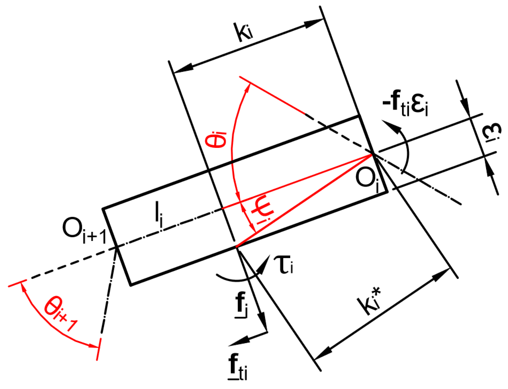
- is the twist of the ith contact point on the ith phalanx (assuming one contact per phalanx) with a corresponding wrench , and the operator “∘” stands for the reciprocal product of screws in the plane.
- is the vector of the resultant of contact forces, , normal to phalanx :
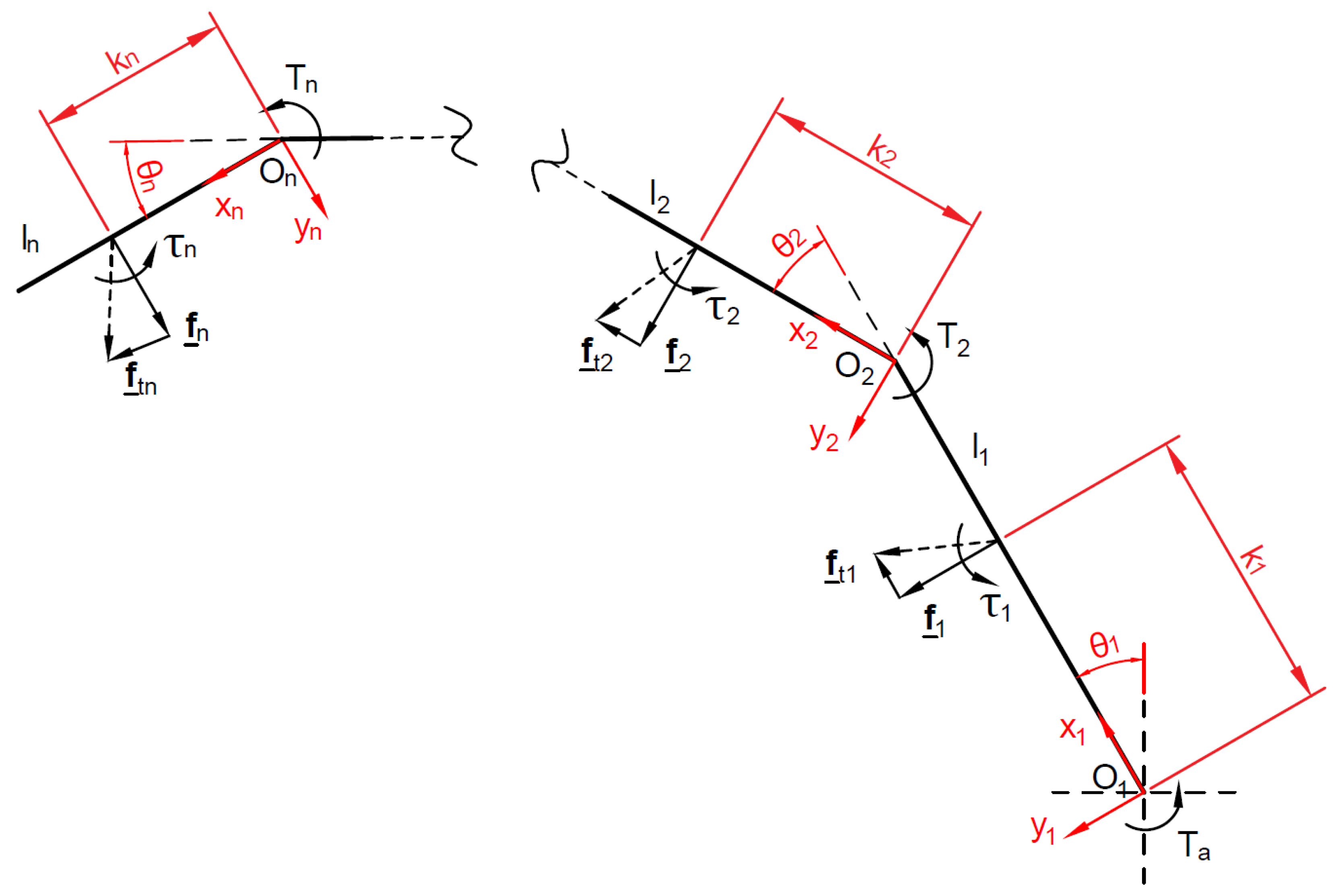
- is the Jacobian Matrix, a square matrix which depends only on the location of the contacts on the phalanges and their relative orientation , their length and the friction coefficients and :
- is the Transmission Matrix, a square matrix which depends on the stage transmission ratios of the mechanism used to propagate the actuation torque to the phalanges:where and are the identity matrix and the zero vector of dimension .
2.1. Impact of Phalanx Thickness
2.2. Positive Definiteness of the Forces
3. Contact Forces Writing for the Proposed Finger Mechanism
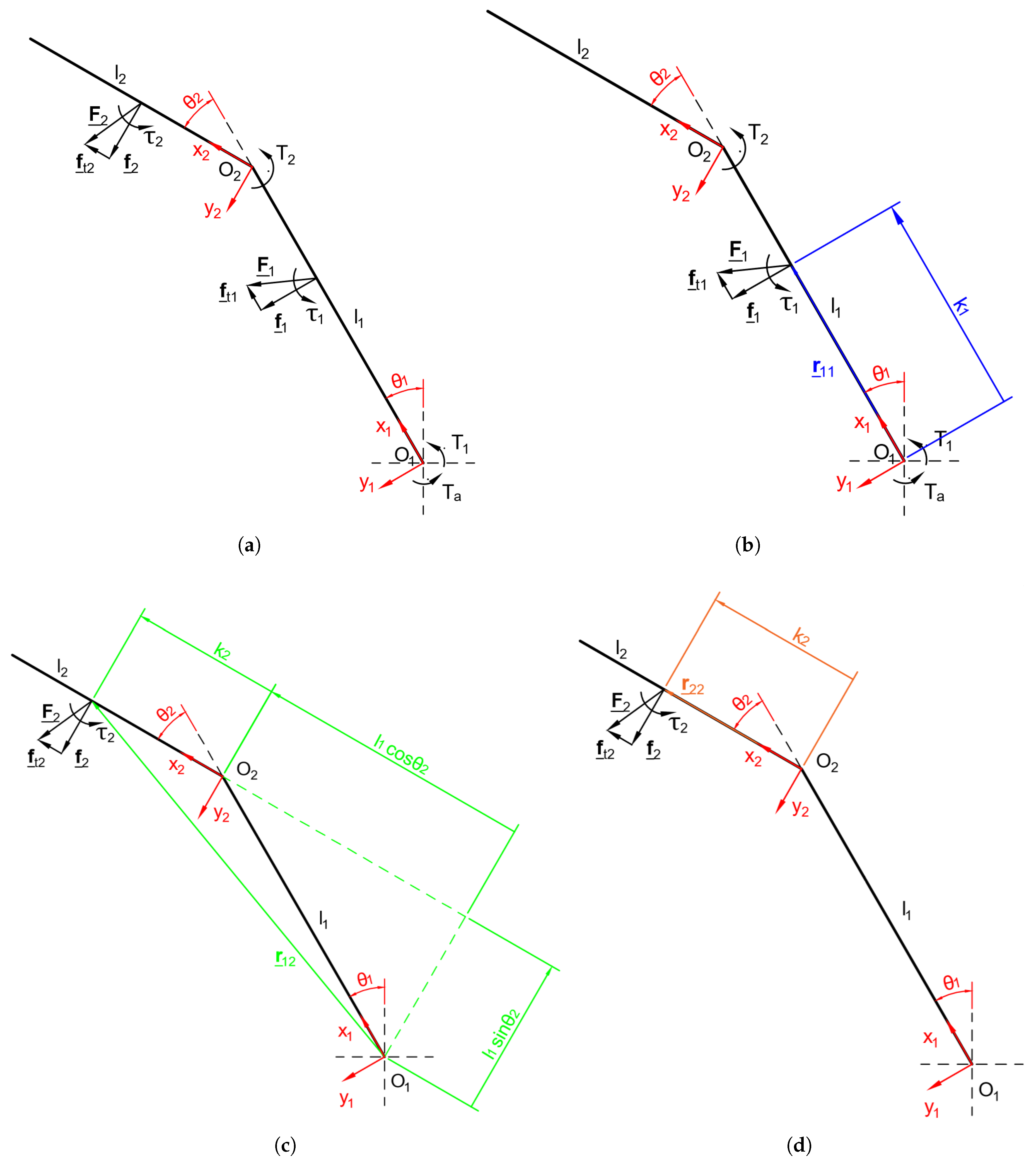
3.1. Two-Phalanx Finger
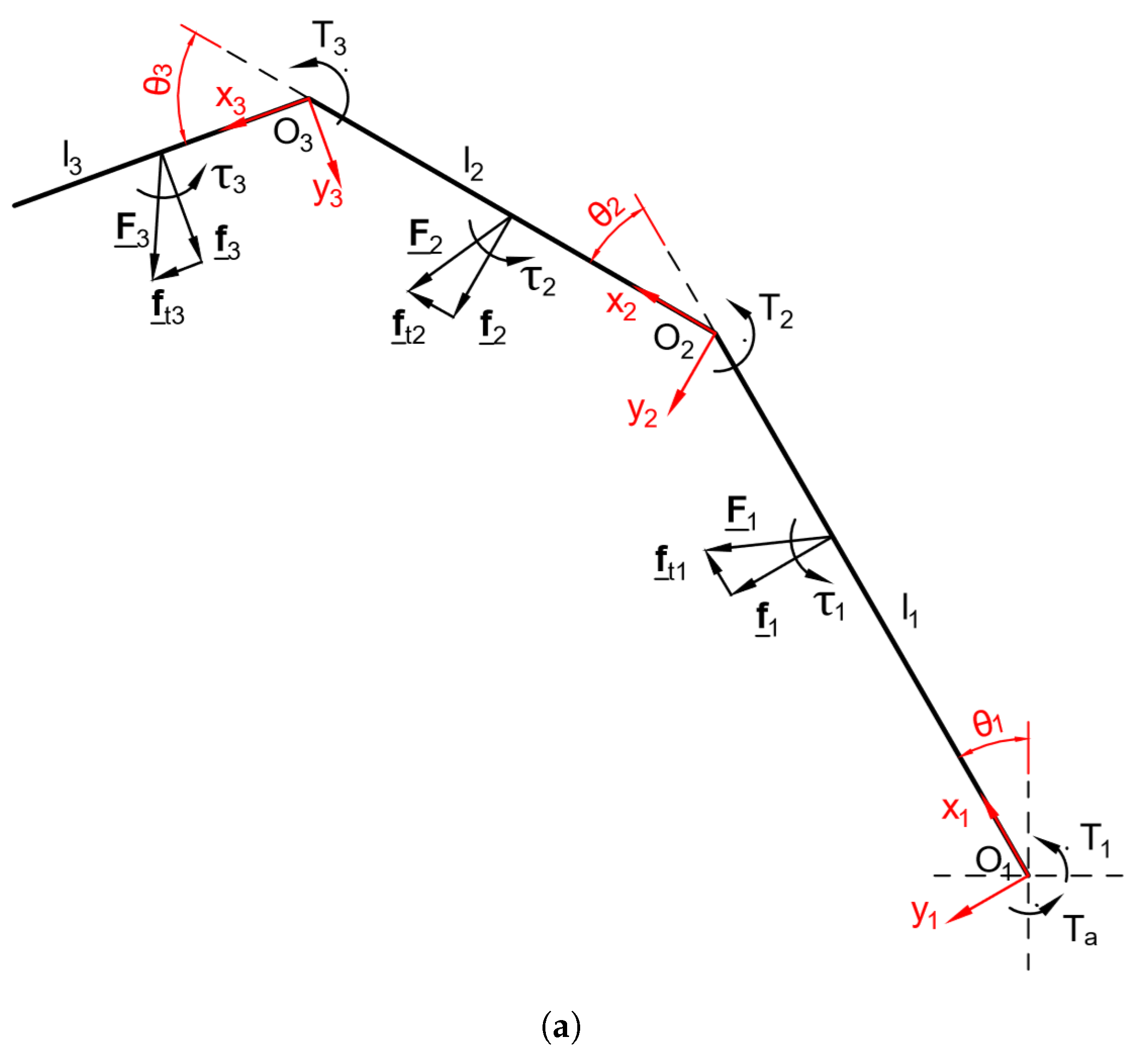
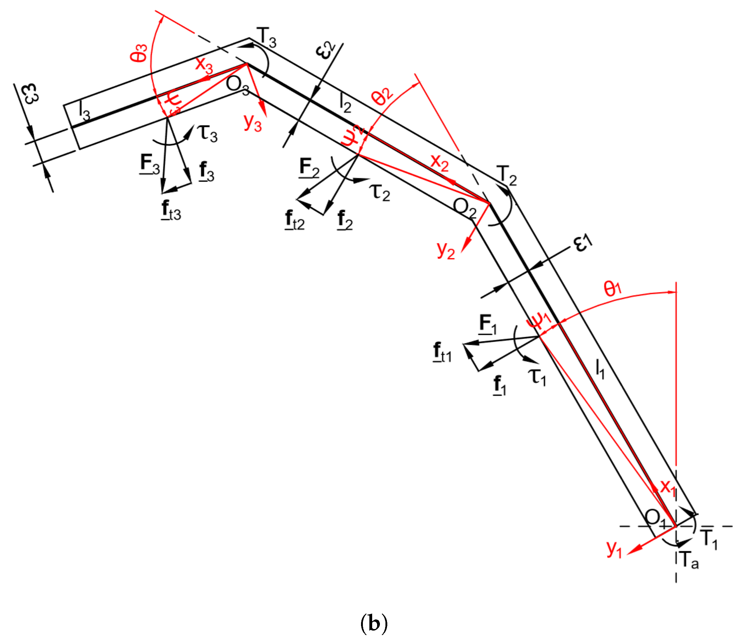
3.2. Three-Phalanx Fingers
4. Proposed Software
- Sections 1 and 2—Phalanx length and semi-thicknessPhalanx lengths can be set by matching those of the human hand, using standard biomechanical measurements ([15]), as shown in Table 1. Phalanx thickness, instead, has been set considering the size of the mechanical transmission, in order to simplify the following design validation and due to the lack of standard biomechanical measurements in the Literature.Note that the software requires as input the phalanx semi-thickness.
- Sections 3, 4, and 5—Springs presence, direction, stiffness, and preloadThe software foresees the adoption of a spring in each joint; when a joint (e.g., , , ) is checked, the rotary spring is activated and the relative stiffness and preload can be set, otherwise the spring is neglected. The user can also choose if the spring opposes opening or closing of the prosthetic hand.As stated before, the proposed mechanism requires a spring in each joint of the finger in order to obtain a statically determined finger.
- Section 6—Friction coefficientsThe user can choose whether or not to consider friction by checking or unchecking the relative button; in the first case the value of friction coefficients and () can be set. These values depend on the material of the object–finger contact: typical values are for a steel–steel contact and for solid–rubber (in both cases clean and non-lubricated [16]). As a matter of fact, it should be considered that robotic finger surfaces can be coated with a rubber-like layer to increase friction or indirectly through the use of a tactile sensing device.It should be also noted that for a given value of two values of should be considered, each corresponding to one sliding direction, i.e., or .
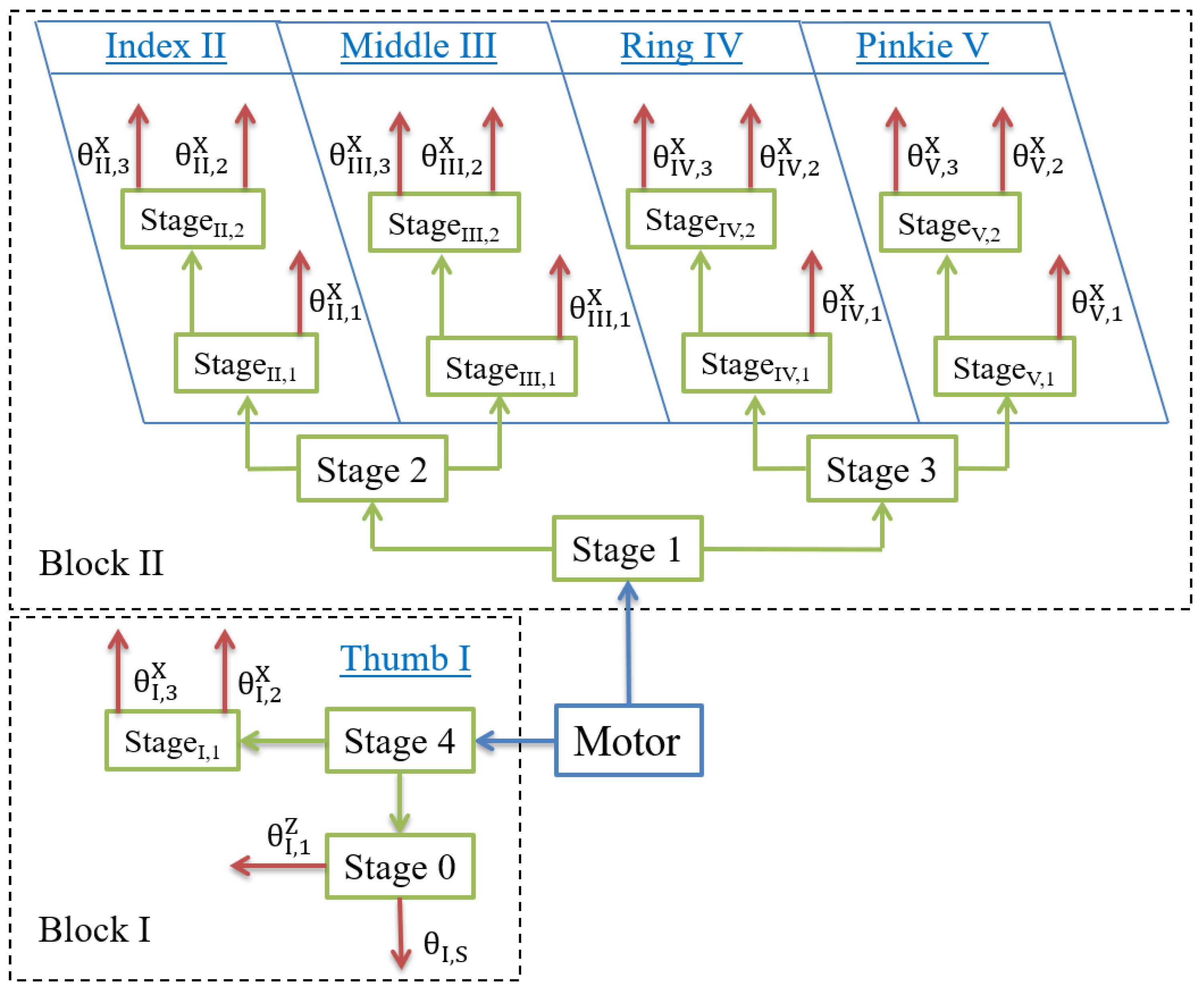
- Section 7—Torque and transmission ratiosThe base joint actuation torque must be provided in order to calculate contact forces. Specifically, in the case of fingers , this torque is found under the assumption that in the steady-state condition it is equally distributed among all fingers.The user can also choose the value of transmission ratios between the phalanges: in order to simplify and speed up the mechanism prototyping, the current version presents unitary transmission ratios.
- Sections 8 and 9—Force application points and flexion anglesThe parameters adopted to study the grasp-state space are the phalanx flexion/extension angles and the force application points, expressed as a percentage of the phalanx length ( and ):
- –
- for two-phalanx fingers this space is of dimensions 3, therefore easily readable on a single graph parameterized as a function of ;
- –
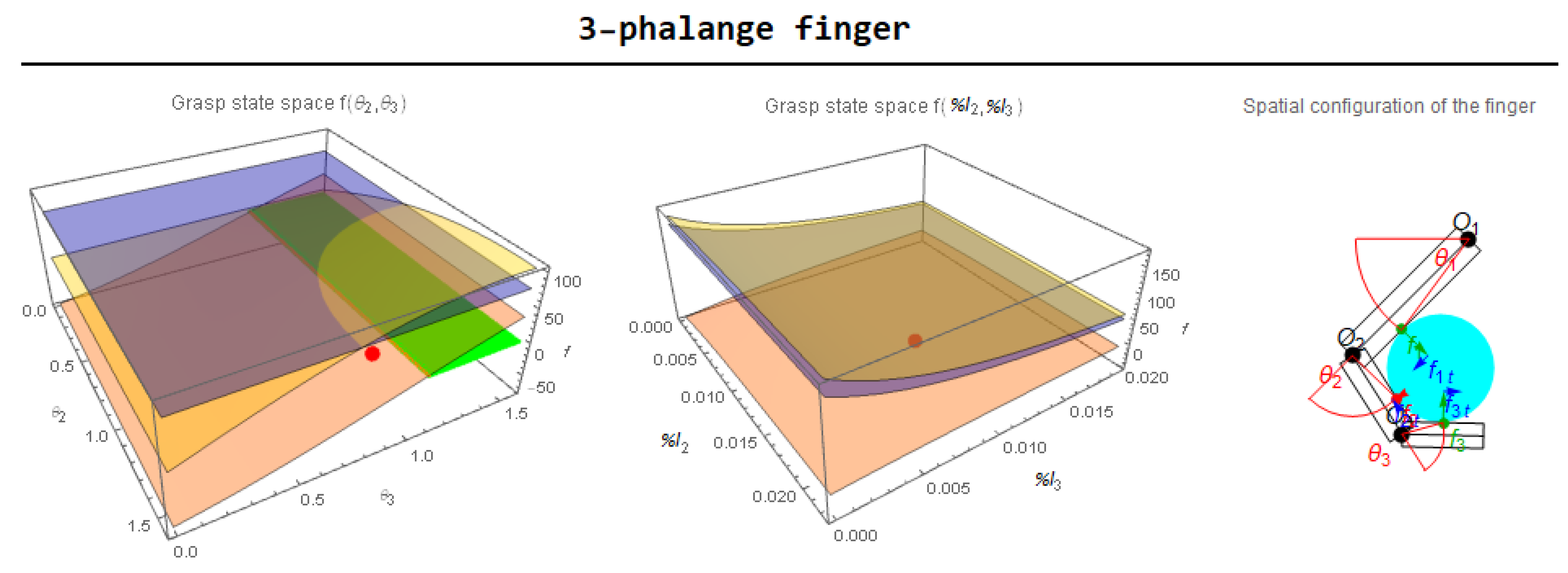
- for three-phalanx fingers, instead, at least two different graphs should be considered: the current version of the software shows the force vector components as a function of in the first graph (on the left of Figure 7) and as a function of in the second graph (on the right) of the same figure. However, other parameters combinations, such as or are easily implementable.
- Section 10—Grasped object parametersWhen the object button is checked, the software working modality is affected: force application points, in this case, are automatically defined by the intersection between the phalanges and the object outer shape. The user can choose the object dimension, shape, and position relative to the finger base joint .
- Section 11—Graphic settingsThe sliders in this section help defining the grasp-state space boundaries both in terms of and . They also define the number of points for which numeric integration of a performance index is performed. This index indicates the percentage of the defined grasp-state space, which allows for a stable grasp. The boundaries for contact forces can also be set, in order to analyze their trend.Moreover, the visualization of each single contact force both in the grasp-state space graphs and in finger schemes can be activated by checking the relative button. In detail:
- -
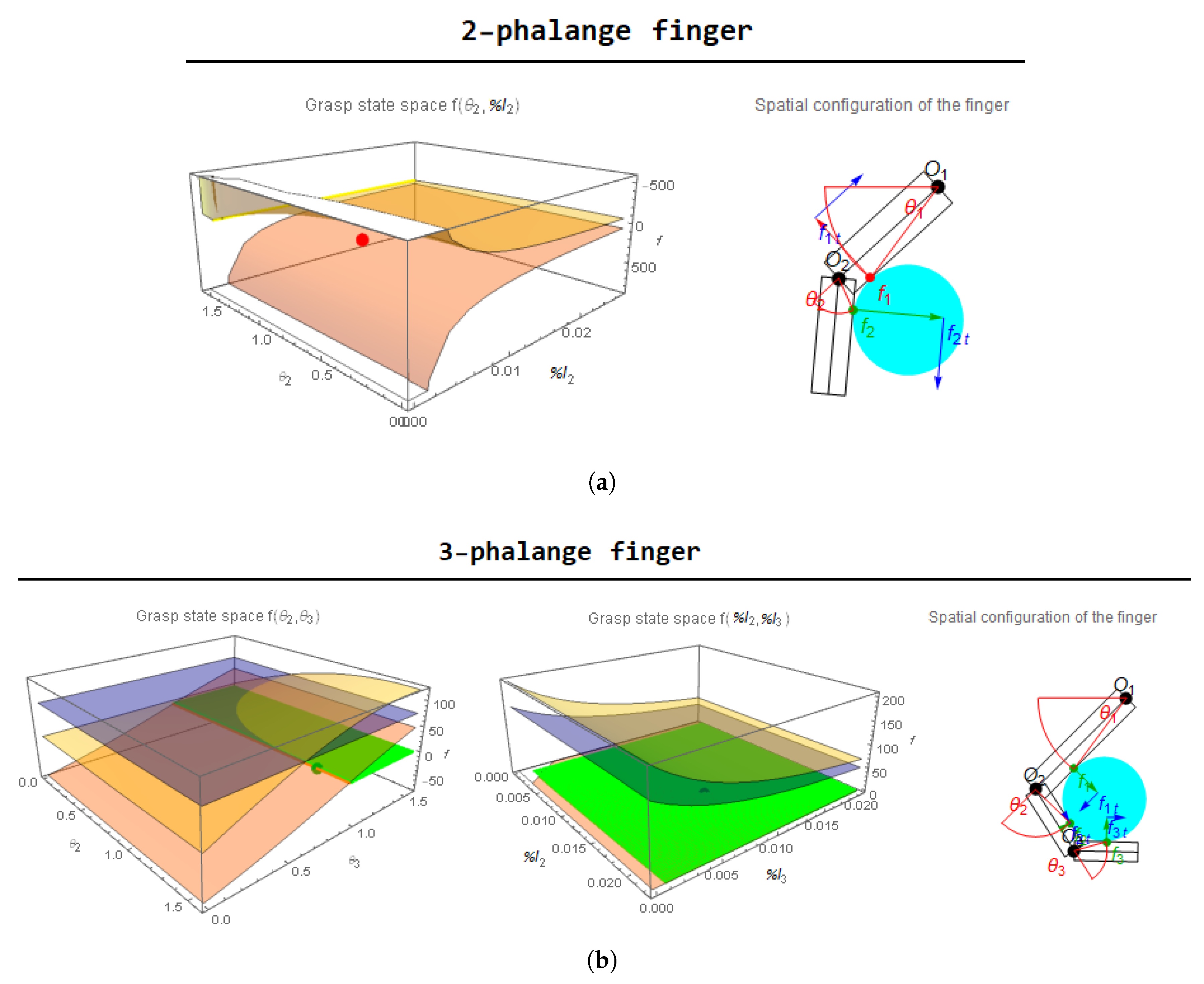
- the contact forces , , and are denoted respectively as yellow, orange, and blue surfaces in the grasp-state space graphs, while the green surfaces indicate the portion of the grasp-state spaces where the forces are all positive, therefore indicating a stable grasp. The green (stable grasp) or red (unstable grasp) point indicates the current configuration of the parameters for the two-phalanx finger or and for the three-phalanx finger;
- -
- the vectors representing the contact forces in the finger schemes are green or red if the forces are, respectively, positive or negative. The blue vectors, instead, indicate the tangential forces acting at the object contact points.
Furthermore, the GUI language can be set (the current version only supports English and Italian). - Section 12—ResultsThis section shows the main analytic outcomes obtained from the software: normal and tangential forces and values of the performance indexes both for two- and three-phalanx fingers. In the configuration considered in Figure 7, the grasped object, a disk, is positioned at the same distance from the base joint for the two finger architectures, but the grasp results stable only for the three-phalanx finger. This is due to the fact that, for the given combination of the chosen parameters, in the case of the two-phalanx finger the force is negative, while in the case of the three-phalanx finger all the forces are positive. Specifically:
- -
- as can be seen in the grasp-state space graph of the two-phalanx finger (Figure 8a), the force —orange surface—is always negative for each value of the parameters, so that the only way to obtain a stable grasp is that of changing the other parameters, such as the phalanx length or thickness, the friction coefficients, or the springs features;
- -
- in the case of the three-phalanx finger (Figure 8b) the first grasp-state space, which is a function of the parameters, shows a stable grasp—green surface—just in the of the defined space, mainly due to the trend of surface; on the other hand, the second grasp-state space, which is a function of the parameters, shows a stable grasp in the of the defined space.
As an example, if in the case of the three-phalanx finger the friction coefficients are modified from to the grasp becomes unstable (as shown in Figure 9); this result highlights the importance of friction in the grasp stability problem and it also shows how this software could be useful in finding the best design parameters for an efficient underactuated gripper.
5. Conclusions
Author Contributions
Funding
Conflicts of Interest
References
- Russo, M.; Ceccarelli, M.; Corves, B.; Hüsing, M.; Lorenz, M.; Cafolla, D.; Carbone, G. Design and Test of a Gripper Prototype for Horticulture Products. Robot. Comput. Integr. Manuf. 2017, 44, 266–275. [Google Scholar] [CrossRef]
- Yao, S.; Ceccarelli, M.; Carbone, G.; Dong, Z. Grasp configuration planning for a low-cost and easy-operation underactuated three-fingered robot hand. Mech. Mach. Theory 2018, 129, 51–69. [Google Scholar] [CrossRef]
- Kragten, G.A.; Herder, J.L. The ability of underactuated hands to grasp and hold objects. Mech. Mach. Theory 2010, 43, 408–425. [Google Scholar] [CrossRef]
- Miller, A.; Allen, P. GraspIt! IEEE Robot. Autom. Mag. 2004, 11, 110–122. [Google Scholar] [CrossRef]
- Leon, B.; Ulbrich, S.; Diankov, R.; Puche, G.; Przybylski, M.; Morales, A.; Asfour, T.; Moisio, S.; Bohg, J.; Kuffner, J.; et al. Opengrasp: A toolkit for robot grasping simulation. Simul. Model. Program. Auton. Robot. 2010, 11, 109–120. [Google Scholar]
- Aukes, D.; Cutkosky, M. Simulation-based tools for evaluating underactuated hand designs. In Proceedings of the 2013 IEEE International Conference on Robotics and Automation (ICRA 2013), Karlsruhe, Germany, 6–10 May 2013; pp. 2067–2073. [Google Scholar] [CrossRef]
- Malvezzi, M.; Gioioso, G.; Salvietti, G.; Prattichizzo, D. SynGrasp: A MATLAB Toolbox for Underactuated and Compliant Hands. Robot. Autom. Mag. IEEE 2015, 22, 52–68. [Google Scholar] [CrossRef]
- Calli, B.; Walsman, A.; Singh, A.; Srinivasa, S.; Abbeel, P.; Dollar, A.M. Benchmarking in Manipulation Research: The YCB Object and Model Set and Benchmarking Protocols. IEEE Robot. Autom. Mag. 2015, 22, 36–52. [Google Scholar] [CrossRef]
- Adam’s Hand. Adam’s Hand Website. Available online: http://www.adamshand.it (accessed on 27 December 2018).
- Zappatore, G.A.; Reina, G.; Messina, A. Adam’s Hand: An Underactuated Robotic End-Effector. In Advances in Italian Mechanism Science; Springer: Cham, Switzerland, 2016; pp. 239–246. [Google Scholar]
- Zappatore, G.A.; Reina, G.; Messina, A. Analysis of a highly underactuated robotic hand. Int. J. Mech. Control 2017, 18, 17–24. [Google Scholar]
- Zappatore, G.A.; Reina, G.; Messina, A. A proposed software framework for studying the grasp stability of underactuated fingers. In Mechanism Design for Robotics, Proceedings of the IFToMM Symposium on Mechanism Design for Robotics, Udine, Italy, 11–13 September 2018; Springer: Cham, Switzerland, 2018; pp. 202–210. [Google Scholar]
- Birglen, L.; Laliberté, T.; Gosselin, C. Underactuated Robotic Hands; Springer: Berlin/Heidelberg, Germany, 2008. [Google Scholar]
- Wolfram, S. Mathematica: A System for Doing Mathematics by Computer; Wolfram Research Inc.: New York, NY, USA, 1988. [Google Scholar]
- Buryanov, A.; Kotiuk, V. Proportions of Hand Segments. Int. J. Morphol. 2010, 28, 755–758. [Google Scholar] [CrossRef]
- Oberg, E.; Jones, F.D.; Horton, H.L.; Ryffell, H.H.; Heald, R.M.; McCauley, C.J. Machinery’s Handbook; Industrial Press: South Norwalk, CT, USA, 2000. [Google Scholar]
- Okamura, A.; Smaby, N.; Cutkosky, M.R. An overview of dexterous manipulation. In Proceedings of the IEEE International Conference on Robotics and Automation, San Francisco, CA, USA, 24–28 April 2000; pp. 255–263. [Google Scholar]


| Phalanx | Thumb (I) | Index () | Middle () | Ring () | Pinkie (V) |
|---|---|---|---|---|---|
| - | |||||
© 2019 by the authors. Licensee MDPI, Basel, Switzerland. This article is an open access article distributed under the terms and conditions of the Creative Commons Attribution (CC BY) license (http://creativecommons.org/licenses/by/4.0/).
Share and Cite
Zappatore, G.A.; Reina, G.; Messina, A. A Toolbox for the Analysis of the Grasp Stability of Underactuated Fingers. Robotics 2019, 8, 26. https://doi.org/10.3390/robotics8020026
Zappatore GA, Reina G, Messina A. A Toolbox for the Analysis of the Grasp Stability of Underactuated Fingers. Robotics. 2019; 8(2):26. https://doi.org/10.3390/robotics8020026
Chicago/Turabian StyleZappatore, Giovanni Antonio, Giulio Reina, and Arcangelo Messina. 2019. "A Toolbox for the Analysis of the Grasp Stability of Underactuated Fingers" Robotics 8, no. 2: 26. https://doi.org/10.3390/robotics8020026
APA StyleZappatore, G. A., Reina, G., & Messina, A. (2019). A Toolbox for the Analysis of the Grasp Stability of Underactuated Fingers. Robotics, 8(2), 26. https://doi.org/10.3390/robotics8020026