Article

On the Design of a Safe Human-Friendly Teleoperated System for Doppler Sonography

by
Juan Sebastián Sandoval Arévalo
*,
Med Amine Laribi
,
Saïd Zeghloul
and
Marc Arsicault
Department of GMSC, Pprime Institute, CNRS, ENSMA, University of Poitiers, UPR 3346 Poitiers, France
*
Author to whom correspondence should be addressed.
Robotics 2019, 8(2), 29; https://doi.org/10.3390/robotics8020029
Submission received: 11 January 2019 / Revised: 12 March 2019 / Accepted: 12 April 2019 / Published: 15 April 2019
(This article belongs to the Special Issue Mechanism Design for Robotics)

Abstract

:
Variable stiffness actuators are employed to improve the safety features of robots that share a common workspace with humans. In this paper, a study of a joint variable stiffness device developed by PPRIME Institute—called V2SOM— for implementation in the joints of a multi-DoF robot is presented. A comparison of the interaction forces produced by a rigid body robot and a flexible robot using the V2SOM is provided through a dynamic simulator of a 7-DoF robot. As an example of potential applications, robot-assisted Doppler echography is proposed, which mainly focuses on guaranteeing patient safety when the robot holding the ultrasound probe comes into contact with the patient. For this purpose, an evaluation of both joint and Cartesian control approaches is provided. The simulation results allow us to corroborate the effectiveness of the V2SOM device to guarantee human safety when it is implemented in a multi-DoF robot.

Graphical Abstract

1. Introduction

The capability of industrial robots to execute tasks significantly faster than humans has improved the efficiency of several industrial processes. However, there exist numerous tasks that are harder to automate, where human execution is required. The use of Cobots (i.e., collaborative robots) appears to be an effective solution to improve the execution of complex tasks where humans are required. Unlike the classical industrial robots, which are usually isolated and avoid physical contact with humans, Cobots share a common workspace with humans and cooperate with them to achieve a desired task [1].
At this time, the use of collaborative robots in medical and industrial applications is rapidly growing. In the context of robot-assisted Doppler sonography, a teleoperated manipulator holds an ultrasound probe and reproduces the same movements over the patient, which are executed by the medical expert manipulating a fictive probe from a master site. In this application, the efforts applied by the manipulator over the patient must be regulated to ensure patient safety and thus, it is important to create compliance in the robot movements.
When using Cobots, the most important issue is to guarantee a safe human–robot coexistence. In this regard, several solutions have been studied [2]. Park et al. led the use of a viscoelastic casing in the robot’s body to reduce consequences of any impact [3]. Fritzsche et al. proposed the supervision of the impact forces by covering the robot’s body with tactile sensors [4]. Human safety can also be ensured by providing the robot with compliant motion capabilities. Two main strategies are defined for this purpose. The first one concerns the use of specific control approaches in order to provide the robot with compliant motions, such as the well-known impedance control [5], admittance control [6] or the compliance control [7] approaches. Some of them react to the external forces applied to the robot, which are either measured by a force/torque sensor or estimated by a disturbance observer [8]. Furthermore, more simple controllers do not need an external torque measure or estimation, such as the one proposed in [7], which uses the potential energy of a virtual spring to perform the compliance motion. On the other hand, a second strategy implementing compliant motion capabilities involves the use of joint compliant mechanisms, allowing us to introduce intrinsic compliance to the robot. For instance, series elastic actuators (SEA) are simple compliant mechanisms, including a mechanical spring between the motor transmission output and the robot link [9]. Unlike the SEA that proposes a constant stiffness, variable stiffness actuators (VSA) are capable of providing adjustable stiffness values according to the requirements [10,11]. Several VSAs have been proposed since the 1980s. Some of them propose mechanical solutions for modifying the stiffness, such as the use of leaf springs [12,13]. Other more complex mechanisms include an extra actuator to vary the stiffness behavior [14,15]. This is also the case for the V2SOM mechanism, a novel rotational variable stiffness actuator that was recently presented by PPRIME Institute. This mechanism presents an innovative stiffness behavior, which is smoothened in the vicinity of zero deflection through the use of a cam-follower mechanism. In the case of collision, stiffness sharply sinks to a steady constant torque threshold, which is tunable according to the load variation [16]. The working principle of V2SOM and an evaluation of its safety performance when implemented on a multi-DoF is presented in this paper.
Various human safety indexes have been studied to validate the effectiveness of the compliant mechanism, such as the head injury criterion (HIC) [17] or the head impact power (HIP) criterion [18], which are used when evaluating the consequences of an impact to the head. These criteria measure the displacements, velocities and accelerations of the head during crash impact tests [19] and are usually used in the automotive sector. Nevertheless, other safety criteria can be employed in robotics, such as the measures of displacements, velocities or accelerations. Furthermore, the measure/estimation of the interaction forces provides significant information for studying the safety behavior of a compliant mechanism.
The validation of safety performance for VSA is typically performed by studying a single-DoF system case. Thus, the collisions between the link attached to the VSA and the environment representing a human being are typically produced and evaluated. Nevertheless, this type of study only provides information about the local safety performance of the compliant mechanism and makes it impossible to evaluate its global performance when using it in a multi-DoF robot.
In this paper, a study of the V2SOM safety performance is presented. Unlike classical studies evaluating the safety performance in a single-DoF model, the presented work studies the performance of a 7-DoF robot using V2SOM on each joint. For this purpose, the dynamic model of a commercial 7-DoF robot has been modified to include the compliant mechanism on each joint. Moreover, two study cases are presented. The first one considers the execution of desired trajectories in joint spaces. In the second one, an application, namely robot-assisted Doppler sonography, is considered. Finally, interaction forces are evaluated according to the human safety index since low accelerations are performed in the application.
This paper is organized as follows. In Section 2, the modeling of a multi-DoF robot using the V2SOM is depicted. Furthermore, joint and cartesian control approaches for executing tracking trajectory tasks are explained. In Section 3, the robot-assisted Doppler sonography application and their issues are presented. A study case for the comparison of the safety performance of a rigid body robot and a robot using the V2SOM on each joint is also presented. A discussion of the obtained results and the conclusions of the presented work are provided at the end of this present paper.

2. Materials and Methods

In the following section, the dynamic model of a multi-DoF robot with joint flexibility that is provided by the implementation of the V2SOM is described. First, the working principle of the V2SOM is depicted. Subsequently, the dynamic robot model with the V2SOM for the execution of tracking trajectory tasks in both the joint and cartesian space is presented.

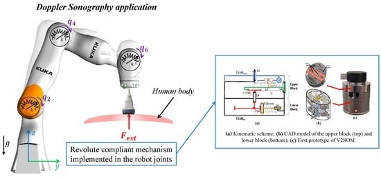
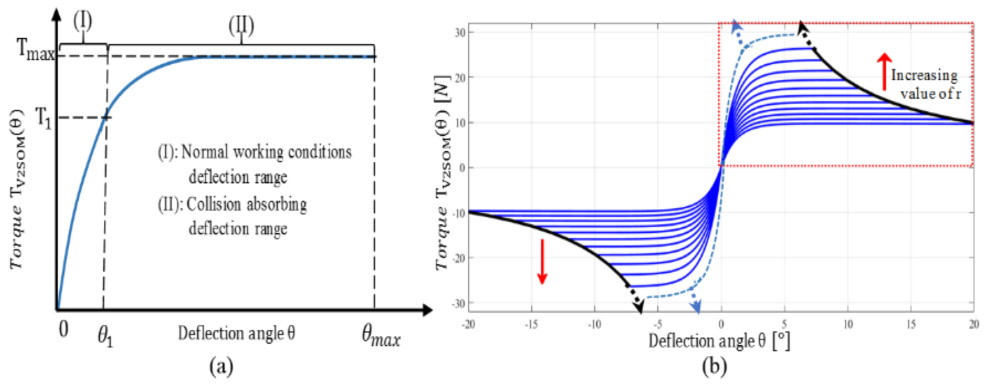
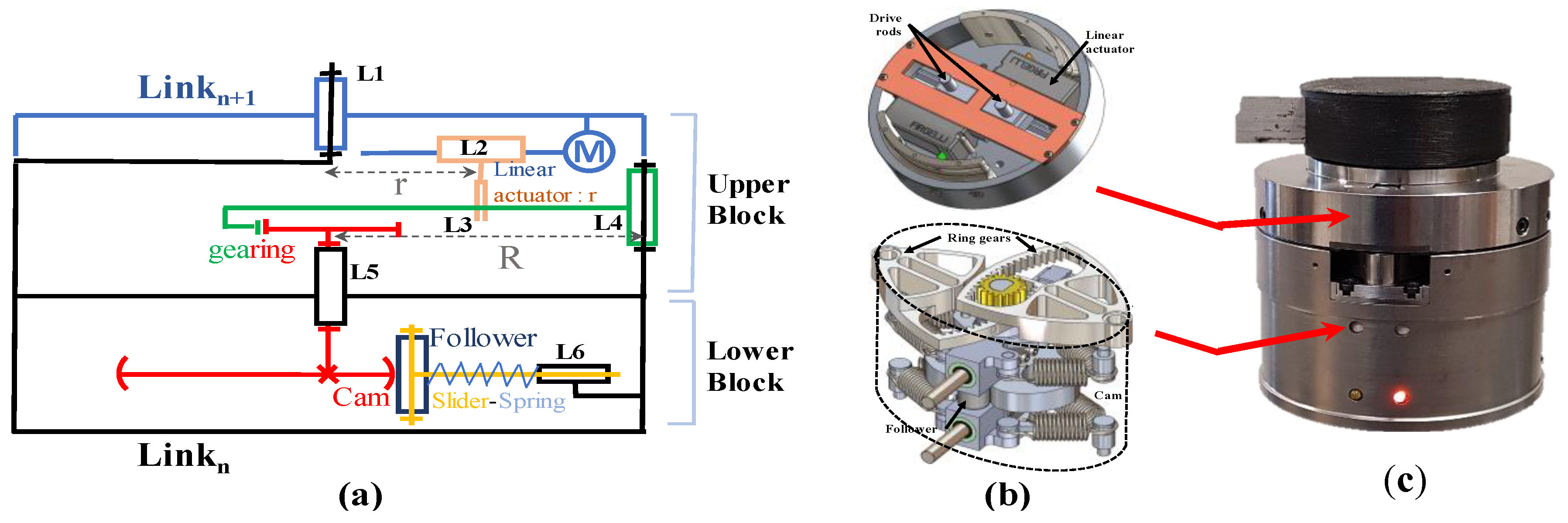
2.1. Working Principle of V2SOM

In order to ensure safe behavior in the event of a collision, a mechanism has been designed to provide a finite torque’s slope when approaching to the zero deflection. When the deflection increases, the stiffness smoothly decreases until it reaches a threshold torque level T m a x . The performance curve of the V2SOM is given by:
T θ = T m a x ( 1 e s θ ) ,
where s is a positive constant value and θ represents the elastic deflection angle.
In general, two working modes are identified for the V2SOM. The transition between the two modes smoothly occurs in the case of a strong collision, as illustrated in Figure 1a. The first mode represents a high stiffness behavior (I) and is defined within a deflection range [ 0 ,   θ 1 ] and a torque range [ 0 ,   T 1 ] , respectively. The value of T 1 defines the limit of normal torque working conditions. When this value is exceeded, the impact absorbing mode (II) is activated, which is characterized by a progressive decrease in the stiffness before reaching the torque threshold T m a x . In the developed V2SOM prototype, the deflection θ 1 corresponds to a torque T 1 = 0.8 · T m a x and supports a maximum deflection θ m a x = π 2 .
The nonlinear behavior is achieved through a cam/follower system. Two blocks form the mechanics of the V2SOM, with each one having a specific task. The two blocks are rigidly coupled as it can be corroborated in the kinematic scheme of the Figure 2a.
The upper block, called the stiffness adjusting block, is basically a deflection angle reducer (torque amplifier) with a tunable reduction ratio. This ratio can continuously be adjusted by modifying the reducer’s tuning parameter r through the actuated joint L 2 . Each value of r leads to a different torque curve with its corresponding T m a x and θ m a x values. Some of these curves are shown in Figure 1b. Moreover, the V2SOM is designed to have a symmetric torque vs. deflection behavior, which allows it to work in two rotation directions. The lower block, called the nonlinear stiffness generator block, is based on a cam/follower mechanism with some additional springs. The cam profile, related to a given positive parameter s , generates the desired torque curve T θ vs. deflection θ (see Equation (1)). The CAD design and an image of the first prototype are shown in Figure 2b,c, respectively. Readers are invited to refer to [20] in order to obtain further details about the design phase of the V2SOM.
In the following section, a description of the dynamic model of a multi-DoF robot with joint flexibility by means of the V2SOM implementation on its joints is presented. The two control designs for executing tasks in the joint and cartesian levels are also depicted.

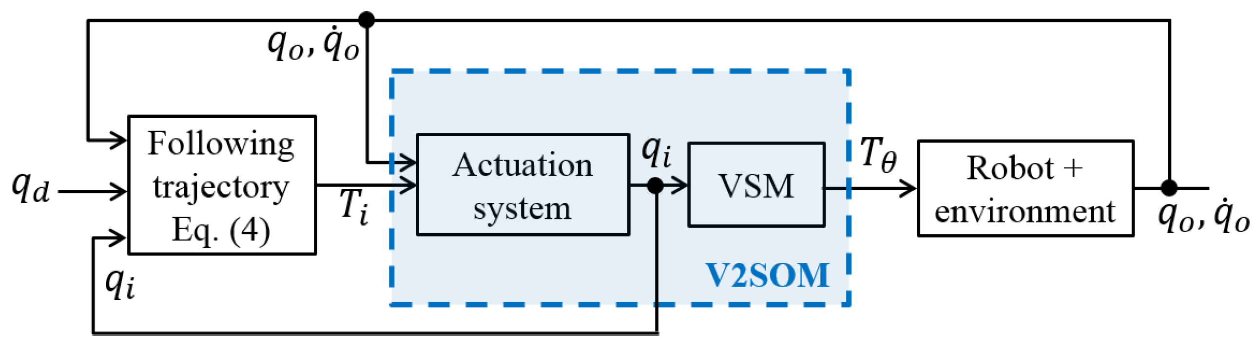
2.2. Joint Control Design

The dynamic modeling of a flexible joint proposed by [21] is useful for representing a n -DoF serial robot implementing V2SOM on each joint as follows:
M ( q o ) q ¨ o + C ( q o , q ˙ o ) q ˙ o + g ( q o ) = T θ + T e x t ,
The vector q o n comprises the link side positions and T θ n contains the output torque provided by V2SOM whose behavior is explained by Equation (1), as shown in Figure 2. The external forces acting on the robot are represented by the torque vector T e x t n . Moreover, the motor side dynamics is defined by:
B q ¨ i + T θ = T i T f ,
where B n × n is the motor inertia matrix, q i n is the vector containing the motor side positions and T i n contains the motor torques. The friction torques are represented by T f n . After this, the elastic deflection angle is defined by θ = q i q o .
Several control approaches can be used to control a robot, including flexible joints, such as the one presented in [22]. This approach was proposed for fast movements, such as pick-and-place applications. In this case, in order to execute joint tracking trajectory tasks, the torque motor T i can be controlled through a PD regulator that is added to a gravity compensation term in a similar way to the approach proposed in [23]:
T i = K p ( q d q i ) K d q ˙ i + g ^ ( q o ) ,
The vector q d n is the desired link side position. Figure 3 shows the block diagram of the implemented control approach. Furthermore, the passivity of the system can be guaranteed by properly choosing the constant values K p and K d .

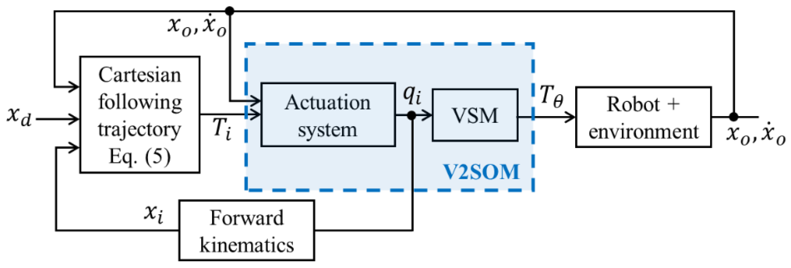
2.3. Cartesian Control Design

In the case of cartesian tracking trajectory tasks of dimension m , the torque motor T i can also be achieved through a PD regulator and a gravity compensation term, as follows:
T i = J T [ K p x ( x d x i ) K d x x ˙ i ] N ( q ) ξ + g ^ ( q o ) ,
where x d m is the vector of the desired end effector positions. Similar to the joint space case, the passivity of the system can be ensured with a proper choice of the constant values K p and K d . J ( q ) m × n is the Jacobian matrix and N ( q ) = I J T J + T is a null space projector that allows us to optimize an objective function represented by ξ . Figure 4 shows the block diagram of the implemented control approach for the cartesian case.

3. Implementation and Results

In this section, the robot-assisted Doppler sonography is first presented. As mentioned above, the use of V2SOM can be useful for this medical application. Subsequently, two study cases allowing us to compare the safety performance between a rigid body and a compliant robot using the V2SOM are presented, where the latter study case concerns the mentioned medical application.

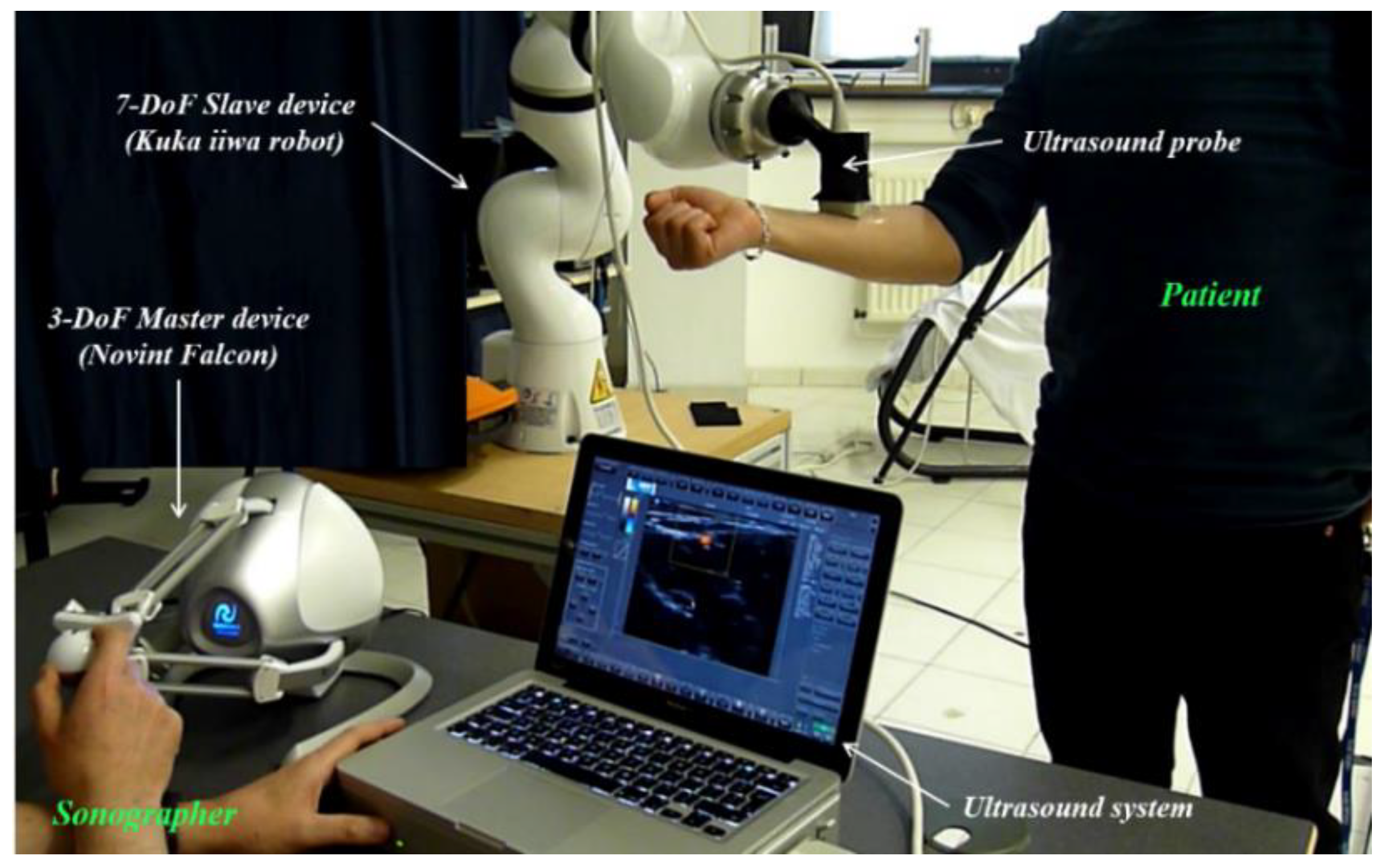
3.1. Robot-Assisted Doppler Sonography

Several studies demonstrate the appearance of work-related musculoskeletal disorders (WRMD) due to the uncomfortable postures adopted by the sonographers during the examinations [24,25]. The motion capture analysis performed during examinations has allowed us to confirm that sonographers frequently take postures completely out of the comfort zone. In order to avoid the existence of WRMD, a robotized platform for Doppler sonography has been proposed by PPRIME Institute. The medical expert, located at the master site, operates a 3DoF haptic device (Figure 5). In a real-life scenario, the sonographer will perform examinations on patients lying on the examination table in the same conditions as in his medical office. The setup shown in Figure 5 is used to perform the first experimental tests. The haptic device pedals the movements of the serial robot and maintains the ultrasound probe over the patient. The use of the master device instead of manually manipulating the probe allows medical experts to restrict their movements to the comfort zone.
In order to ensure safe patient–robot contact, it is important to create compliant behavior in the slave robot. Therefore, compliance can be provided by implementing V2SOM on each joint of the robot. A study case is provided below for a classical trajectory executed at the beginning of a robot-assisted Doppler sonography examination.

3.2. Study Cases

Hereafter, some preliminary results of the safety performance of a multi-DoF collaborative robot using V2SOM to provide it with joint flexibility are presented. A 7-DoF Kuka IIWA robot has been used for this experience. This is one of the most relevant torque-controlled collaborative robots that are employed by the research community.

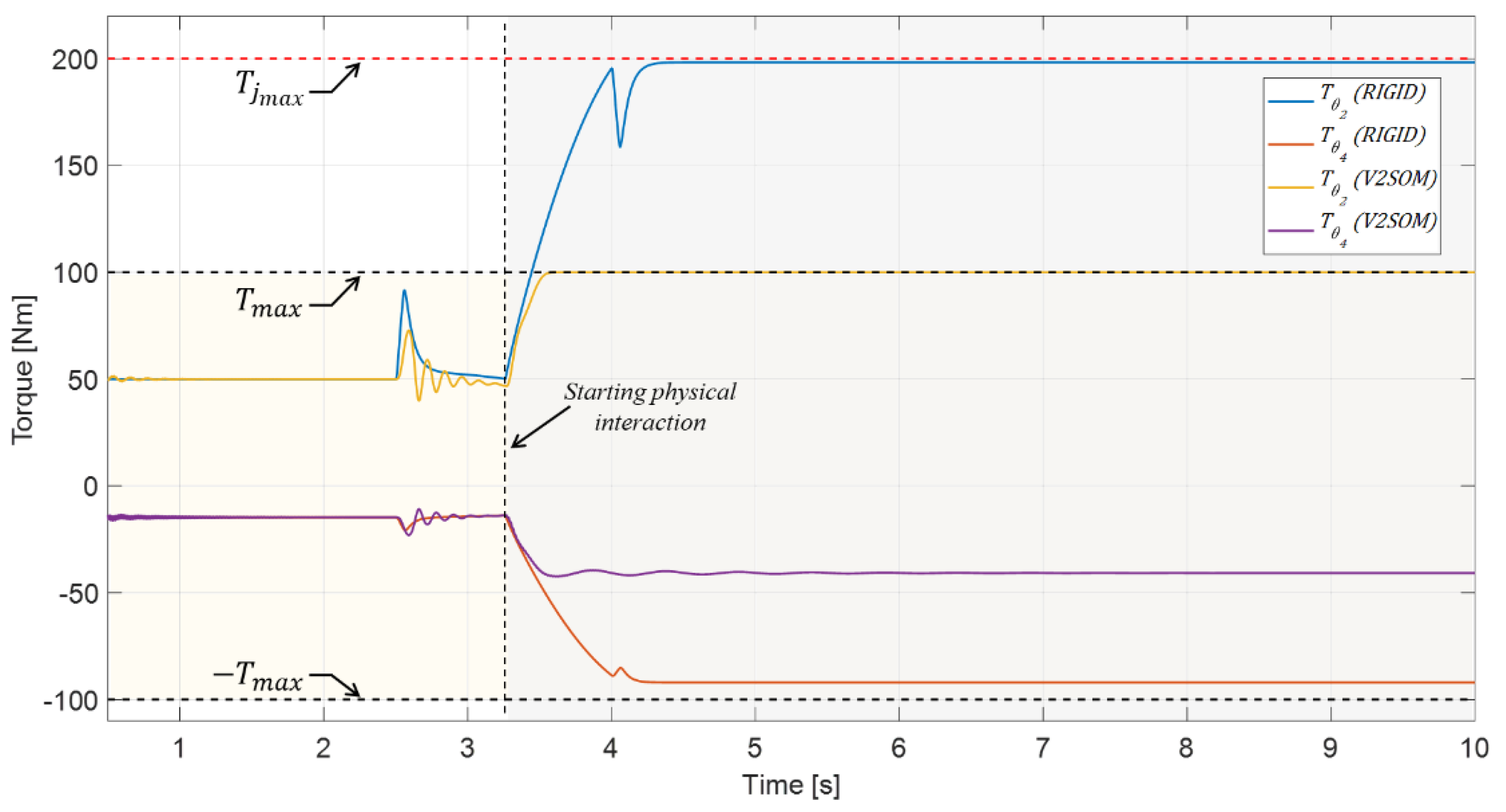
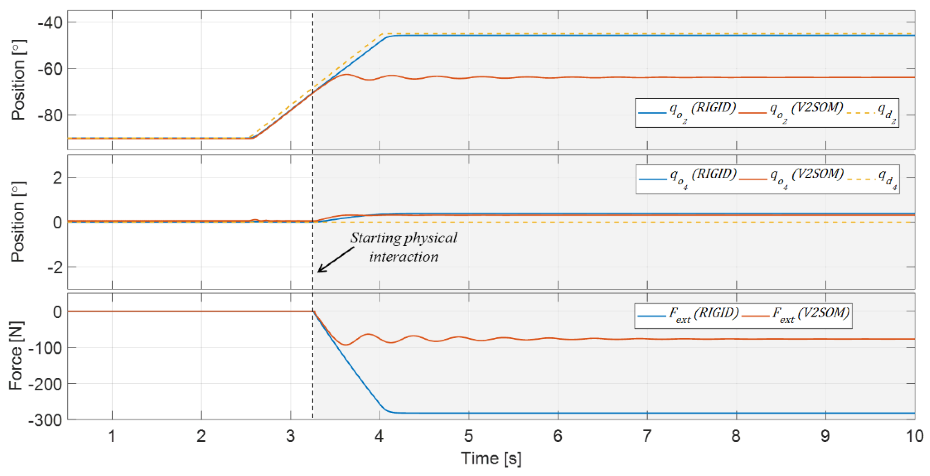
3.2.1. Joint Space Trajectory Task

For this first experience, the cartesian workspace is restrained to the YZ plane. According to this restriction, only the movements on joints 2 and 4 are activated, while the rest of the joints have been blocked to fixed joint position values. The link side position vector is defined as q o = { π / 2 ,   q o 2 π / 2 ,   0 ,   q o 4 ,   0 ,   0 ,   0 } .
After this, the proposed V2SOM is implemented in the second and fourth joints with the purpose to provide safe compliant behavior in the case of a collision with an external object. A joint desired linear trajectory for the joint 2 is defined, i.e., q d 2 from 0° to 90°. For joint 4, a fixed desired angle q d 4 = 0 ° was set. A compliant object is placed on the robot’s workspace, which interferes with its trajectory. The external compliant object is characterized by certain stiffness and damping values of k e = 1000 N/m and d e = 10 Ns2/m, respectively. Figure 6a illustrates the proposed study case.
The constant parameters were defined as follows: K p = d i a g { 4000 ,   12000 ,   4000 ,   12000 ,   4000 ,   4000 ,   4000 } and K d = d i a g { 300 ,   811 ,   300 ,   811 ,   300 ,   300 ,   0.15 } . Friction effects were neglected for the sake of simplicity, i.e., T f 0 . Furthermore, the compliance parameters of the V2SOM for joints 2 and 4 were selected as follows: T m a x = ± 100 Nm and s = 184.428 rad−1 for a deflection value θ 1 = 0.5 ° . Figure 7 and Figure 8 show the obtained simulation results for this study case. A comparison between the robot’s behavior in two different compliance configurations is presented: when using a rigid body robot (i.e., T θ T i ) and when V2SOM is implemented in joints 2 and 4. Considering the low velocities used in these examinations, the HIC and HIP criteria are not suitable for evaluating the safety performance of the robot. Thus, the interaction forces F e x t induced for the two configurations are proposed for the safety performance index.
The interaction force F e x t generated during the physical contact between the robot and the compliant object naturally induces a variation in the joint position signals. In the case of a rigid body robot implementing a classical joint position control strategy, the PD regulator, directed by the constant values K p and K d , are forced to reach the desired trajectory using the maximum torque provided by the motor. This behavior can be verified in Figure 7 and Figure 8, where joint 2 reaches its motor torque limit T j m a x (±200 Nm according to the manufacturer) that provides a joint trajectory close to the desired one. As expected, this behavior also increases the magnitude of the interaction force (Figure 7, bottom). On the other hand, the intrinsic compliance provided by the proposed mechanism induces a decrease in the interaction force, which naturally causes a loss of accuracy in the following trajectory task. Moreover, it can be verified in Figure 8 that the variable stiffness law provided by V2SOM limits the motor torques to the defined torque threshold T m a x = ± 100 Nm. It is worth mentioning that the torque variations generated from t = 2.5 s correspond to the variation of the desired trajectory for joint 2.

3.2.2. Cartesian Space Trajectory Task for Doppler Sonography

In the context of robot-assisted Doppler sonography, the robot holding the probe is first positioned at its zero position (the probe is placed over the patient). After this, the robot executes a vertical trajectory until it comes into contact with the patient’s body. This vertical trajectory corresponds to the first part of the proposed desired 3D cartesian trajectory, which is denoted as x d ( t ) . During the second part, the robot moves away from the patient’s body. In real life conditions, once this trajectory is executed, the sonographer is able to teleoperate the robot using the haptic device.
For this study case, the patient’s body is represented as a compliant entity characterized by certain stiffness k e = 3000 N/m and damping d e = 30 Ns2/m values, respectively. Figure 6b illustrates the proposed study case.
Constant parameters have been fixed as: K p x = d i a g { 6000 ,   6000 ,   6000 } and K d x = d i a g { 300 ,   300 ,   300 } . Similar to the previous study case, friction effects have been neglected (i.e., T f 0 ) and the compliance parameters of the V2SOM were selected as: T m a x = ± 30 Nm and s = 184.428 rad−1 for a deflection value θ 1 = 0.5 ° . The objective function was employed to stabilize the internal motion by reducing the joint velocities, i.e., ξ = 0.1 q ˙ i .
The robot’s behavior in three different configurations are compared: when using a rigid body robot, i.e., T θ T i ; when a linear compliant behavior is implemented (constant stiffness); and when the V2SOM is implemented on each joint of the robot. The obtained results are shown in Figure 9 and Figure 10.
As expected for the medical application, the compliance behavior provided by the V2SOM decreases the interaction forces (Figure 9 bottom). Furthermore, the z-axis trajectory performed by the robot using V2SOM does not affect the quality of the Doppler test since the contact between the probe and human body is established and guaranteed. Figure 10 proves that the output torques provided by V2SOM are always restricted by the desired limits T m a x = ± 30 Nm unlike the motor torque signals of the rigid body and constant stiffness cases.

4. Discussion

In the first study case, Figure 7 shows the position signals of joint 2 and the interaction force induced by the collision between the robot’s wrist and the compliant object in the two configurations. The magnitude of this interaction force represents a safety index, which indicates a more human-friendly behavior when low values are measured. In this case, Figure 7 allows us to verify that the interaction force F e x t has significantly decreased for the configuration when using V2SOM in joints 2 and 4, which proves its safer performance.
Figure 8 shows the control torque signals for joints 2 and 4 in the two configurations. It is possible to verify that the output torque T θ provided by the V2SOM that is implemented in joint 2 is constrained by the torque threshold T m a x at a time of around 3.6 s. In contrast, the torque signals of the rigid body configuration are only restricted by the motor torque limits T j m a x .
In the second study case, the current position signals on the z-axis and the interaction force generated by the collision between the probe and the patient’s body for the three configurations are shown in Figure 9. Similar to the previous case, it is shown that the interaction force F e x t has considerably decreased when using the V2SOM, which demonstrates safer performance compared to the rigid body robot configuration.
Although the external efforts generated during the physical interaction are experienced by all the robot joints, Figure 10 allows us to verify that the efforts felt by joint 4 are particularly important as they reach the torque threshold T m a x of 30 Nm. An opposing case can be seen for the rigid body and the linear compliance configurations as the only restriction imposed to the joint torques concerns the motor torque limits, which are not reached for this case.
It is worth mentioning that the use of V2SOM intrinsically improves the safety performance of the multi-DoF robot used in the teleoperation system, as verified by the interaction forces in the presented study cases. Further details about the safety performance evaluation of V2SOM through an evaluation of safety criteria can be found in [26,27].

5. Conclusions

In this paper, the safety performance of a collaborative robot using the V2SOM, a variable stiffness mechanism conceived by PPRIME Institute, has been presented. A dynamic simulator to integrate the nonlinear compliant behavior of the V2SOM to the joints of a 7-DoF collaborative robot (i.e., a Kuka IIWA robot) has been developed. The dynamic robot’s model has been modified to include the V2SOM compliance model. Two study cases were proposed to evaluate the safety performance of the modeling system. Firstly, the physical interaction between the robot and a compliant object when executing joint space trajectories was studied. Secondly, the use of the modified robot model for a medical application, namely robot-assisted Doppler sonography, was presented, where the forces applied by the robot holding the ultrasound probe over the patient must be minimized. Several comparisons were made in terms of the safety performance between the robot using and without using the V2SOM which mainly considers the generated interaction forces as a consistent safety criterion. This provides evidence of a safer response when the V2SOM is implemented.

Author Contributions

J.S.S.A. designed the experiments and co-wrote the paper with M.A.L. The research work was supervised by S.Z. and M.A.

Funding

This research was funded by the French National Research Agency, convention ANR-14-CE27-0016, under the ANR project SISCob “Safety Intelligent Sensor for Cobots”. This research was also supported by the French region “Nouvelle-Aquitaine” (program HABISAN 2015-2020) with the financial participation of the European Union (FEDER/ERDF, European Regional Development Fund).

Acknowledgments

This work was sponsored by the French government research program Investissements d’avenir through the Robotex Equipment of Excellence (ANR-10-EQPX-44).

Conflicts of Interest

The authors declare no conflict of interest.

References

  1. Gillespie, R.B.; Colgate, J.E.; Peshkin, M.A. A general framework for cobot control. IEEE Trans. Rob. Autom. 2001, 17, 391–401. [Google Scholar] [CrossRef]
  2. De Santis, A.; Siciliano, B.; De Luca, A.; Bicchi, A. An atlas of physical human–robot interaction. Mech. Mach. Theory 2008, 43, 253–270. [Google Scholar] [CrossRef]
  3. Park, J.J.; Haddadin, S.; Song, J.B.; Albu-Schäffer, A. Designing optimally safe robot surface properties for minimizing the stress characteristics of human-robot collisions. In Proceedings of the 2011 IEEE International Conference on Robotics and Automation, Shanghai, China, 9–13 May 2011; pp. 5413–5420. [Google Scholar]
  4. Fritzsche, M.; Elkmann, N.; Schulenburg, E. Tactile sensing: A key technology for safe physical human robot interaction. In Proceedings of the 6th International Conference on Human-Robot Interaction (HRI ‘11), Lausanne, Switzerland, 6–9 March 2011; pp. 139–140. [Google Scholar]
  5. Chiaverini, S.; Siciliano, B.; Villani, L. A survey of robot interaction control schemes with experimental comparison. IEEE/ASME Trans. Mechatron. 1999, 4, 273–285. [Google Scholar] [CrossRef]
  6. Ott, C.; Mukherjee, R.; Nakamura, Y. A hybrid system framework for unified impedance and admittance control. J. Intell. Rob. Syst. 2014, 78, 359–375. [Google Scholar] [CrossRef]
  7. Dietrich, A.; Wimbock, T.; Albu-Schaffer, A.; Hirzinger, G. Integration of reactive, torque-based self-collision avoidance into a task hierarchy. IEEE Trans. Rob. 2012, 28, 1278–1293. [Google Scholar] [CrossRef]
  8. Sadeghian, H.; Keshmiri, M.; Villani, L.; Siciliano, B. Null-space impedance control with disturbance observer. In Proceedings of the IEEE/RSJ International Conference on Intelligent Robots and Systems, Vila Moura, Portugal, 7–12 October 2012; pp. 2795–2800. [Google Scholar]
  9. Pratt, G.A.; Williamson, M.M. Series elastic actuators. In Proceedings of the 1995 IEEE/RSJ International Conference on Human Robot Interaction and Cooperative Robots, Pittsburgh, PA, USA, 5–9 August 1995; pp. 399–406. [Google Scholar]
  10. Bicchi, A.; Tonietti, G.; Bavaro, M.; Piccigallo, M. Variable stiffness actuators for fast and safe motion control. Rob. Res. 2005, 15, 527–536. [Google Scholar]
  11. Grioli, G.; Wolf, S.; Garabini, M.; Catalano, M.; Burdet, E.; Caldwell, D.; Carloni, R.; Friedl, W.; Grebenstein, M.; Laffranchi, M.; et al. Variable stiffness actuators: The user’s point of view. Int. J. Rob. Res. 2015, 34, 727–743. [Google Scholar] [CrossRef]
  12. Morita, T.; Sugano, S. Design and development of a new robot joint using a mechanical impedance adjuster. In Proceedings of the 1995 IEEE International Conference on Robotics and Automation, Nagoya, Japan, 21–27 May 1995; pp. 2469–2475. [Google Scholar]
  13. Groothuis, S.; Carloni, R.; Stramigioli, S. A Novel Variable Stiffness Mechanism Capable of an Infinite Stiffness Range and Unlimited Decoupled Output Motion. Actuators 2014, 3, 107–123. [Google Scholar] [CrossRef]
  14. Wolf, S.; Hirzinger, G. A new variable stiffness design: Matching requirements of the next robot generation. In Proceedings of the IEEE International Conference on Robotics and Automation (ICRA 2008), Pasadena, CA, USA, 19–23 May 2008; pp. 1741–1746. [Google Scholar]
  15. Schiavi, R.; Grioli, G.; Sen, S.; Bicchi, A. VSA-II: A novel prototype of variable stiffness actuator for safe and performing robots interacting with humans. In Proceedings of the International Conference on Robotics and Automation (ICRA 2008), Pasadena, CA, USA, 19–23 May 2008; pp. 2171–2176. [Google Scholar]
  16. Ayoubi, Y.; Laribi, M.A.; Arsicault, M.; Zeghloul, S.; Courreges, F. Mechanical device with variable compliance for rotary motion transmission. FR/IFBT17CNRCOB. 2017. [Google Scholar]
  17. National Highway Traffic Safety Administration, Department of Transportation (DOT). Occupant Crash Protection—Head Injury Criterion S6.2 of MVSS 571.208; Docket 69-7, Notice 17; NHTSA: Washington, DC, USA, 1972.
  18. Newman, J.A.; Shewchenko, N.; Welbourne, E. A proposed new biomechanical head injury assessment function—the maximum power index’. In Proceedings of the 44th Stapp Car Crash Conference, Atlanta, GA, USA, 6–8 November 2000. SAE Paper No. 2000-01-SC16. [Google Scholar]
  19. López-Martínez, J.J.; García-Vallejo, D.D.; Giménez-Fernández, A.A.; Torres-Moreno, J.L. A Flexible Multibody Model of a Safety Robot Arm for Experimental Validation and Analysis of Design Parameters. ASME. J. Comput. Nonlinear Dynam. 2013, 9, 011003–011003-10. [Google Scholar]
  20. Sandoval, J.; Laribi, M.A.; Zeghloul, S.; Arsicault, M.; Poisson, G. Safety performance of a variable stiffness actuator for collaborative robots. In Advances in Service and Industrial Robotics; RAAD 2018, Ed.; Mechanisms and Machine Science. (In press)
  21. Spong, M. Modeling and control of elastic joint robots. ASME J. Dyn. Syst. Meas. Contr. 1987, 109, 310–319. [Google Scholar] [CrossRef]
  22. Tonietti, G.; Schiavi, R.; Bicchi, A. Design and Control of a Variable Stiffness Actuator for Safe and Fast Physical Human/Robot Interaction. In Proceedings of the 2005 IEEE International Conference on Robotics and Automation, Barcelona, Spain, 18–22 April 2005; pp. 526–531. [Google Scholar]
  23. Albu-Schäffer, A.; Ott, C.; Hirzinger, G. A Unified Passivity-based Control Framework for Position, Torque and Impedance Control of Flexible Joint Robots. Int. J. Rob. Res. 2007, 26, 23–39. [Google Scholar] [CrossRef]
  24. Gill, H.; Allison, H. Work-related musculoskeletal disorders in ultrasound: Can you reduce risk? Ultrasound 2015, 23, 224–230. [Google Scholar] [CrossRef] [PubMed]
  25. Village, J.; Trask, C. Ergonomic analysis of postural and muscular loads to diagnostic sonographers. Int. J. Ind. Ergon. 2007, 37, 781–789. [Google Scholar] [CrossRef]
  26. Ayoubi, Y.; Laribi, M.A.; Zeghloul, S.; Arsicault, M. V2SOM: A Novel Safety Mechanism Dedicated to a Cobot’s Rotary Joints. Robotics 2019, 8, 18. [Google Scholar] [CrossRef]
  27. Ayoubi, Y.; Laribi, M.A.; Zeghloul, S.; Arsicault, M. Design of V2SOM: The Safety Mechanism for Cobot’s Rotary Joints. In Mechanism Design for Robotics. MEDER 2018. Mechanisms and Machine Science; Gasparetto, A., Ceccarelli, M., Eds.; Springer: Cham, The Netherlands, 2019; Volume 66. [Google Scholar]
Figure 1. (a) Working modes of the V2SOM; and (b) Various performance curves of the V2SOM according to different values of r (tunable reduction ratio).
Robotics 08 00029 g001
Figure 2. (a) Kinematic scheme; (b) CAD model of the upper block (top) and lower block (bottom); and (c) First prototype of V2SOM.
Robotics 08 00029 g002
Figure 3. Block diagram of the proposed joint space control architecture.
Robotics 08 00029 g003
Figure 4. Block diagram representing the proposed cartesian space control architecture.
Robotics 08 00029 g004
Figure 5. Teleoperated system for Doppler echography.
Robotics 08 00029 g005
Figure 6. (a) First study case: a 7-DoF robot using V2SOM in joints 2 and 4 executes a trajectory within a planar workspace while a compliant object obstructs with the desired trajectory. (b) Second Study case: a 7-DoF robot integrating V2SOM on each joint executes a 3D trajectory until getting in contact with the human body.
Robotics 08 00029 g006
Figure 7. (Top) Position signals for joints 2 and 4 in the two cases: with (“V2SOM”) and without (“RIGID”) using the V2SOM. (Bottom) Interaction force F e x t generated in these two cases.
Robotics 08 00029 g007
Figure 8. Link side torque signals T θ 2 , 4 generated by joints 2 and 4 in both cases: when using a rigid body robot and when the output torques are provided by the implemented V2SOMs.
Robotics 08 00029 g008
Figure 9. (Top) Current position along the z-axis; and (Bottom) Interaction force F e x t measured for the three configurations: rigid body, constant stiffness and when using the V2SOM.
Robotics 08 00029 g009
Figure 10. Link side torque signals T θ in each compliant joint for the three different configurations: rigid body, constant stiffness and when using the V2SOM.
Robotics 08 00029 g010

