1. Introduction
The constant technological advances and achievements in human-oriented health sciences has contributed to improve the quality of life of people and has contributed to increase the numbers of the elderly population above 65 years old [
1]. The development of information technologies was originally conceived as a productivity tool but now is widely extended and applied to common population through the use of smart devices, distributed sensor networks, and the internet of things, conditioning the behavior of our society and the way that daily routines are performed. The incorporation of information technologies on environments with elders and people with some disabilities has improved their quality of life through the integration and use of different devices, systems, and methods. In this direction, the field of Ambient Assisted Living (AAL) addresses the implementation of Ambient Intelligent (AmI) systems [
2] and the development of supporting devices [
3].
Smart homes and other smart environments are ideal scenarios for deploying AmI and AAL solutions through the use of fixed embedded devices and sensor networks [
4], and mobile, adaptive and reactive robotics. For example Bazzano et al. [
5] proposed the use of a robot as an interactive receptionist and for wayfinding, showing that physical robots have a higher level of acceptance when compared to virtual agents. However, the coexistence and collaboration of mobile robots with elderly people [
6] or people with disabilities also requires the consideration of psychological and ethical aspects. In [
7,
8] some guidelines are discussed on developing mobile robots for elders, also showing the obtained results based on user feedback and observations during their deployment in a real scenario. Although AAL systems are designed to ease and improve the global quality of life through reaching high levels of automatization, it is also important to evaluate the profile of the target user. This becomes especially important in elders, as encouraging them to be part of the solution rather than letting a device do all the work for them will increase user acceptance and minimize the dignity impact they perceive for relying on such devices. This concept must be considered when providing solutions to people with or without walking mobility limitations, for example, the fulfillment of walking exercises is considered essential to keep independence of elderly people and has also a direct impact on their physical [
9] and psychological health [
10].
This paper proposes the integration of a walk-helper functionality into a multipurpose assistive mobile robot that has already been developed. This application as a walk-helper is an extension of an initial conceptual idea proposed in Martínez et al. [
11].
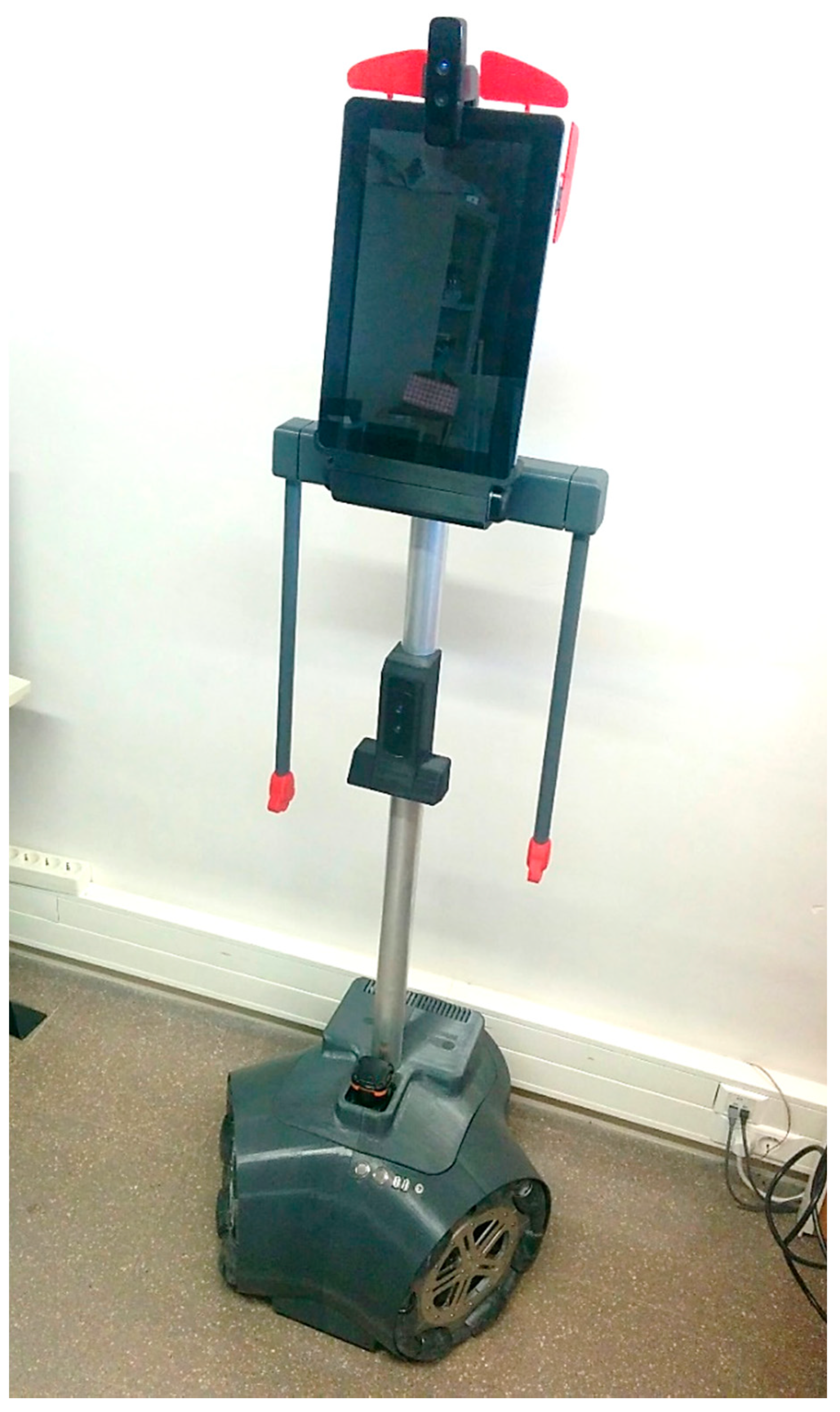
Figure 1 shows an image of the mobile robot used in this paper which is an autonomous version of the prototype described in Clotet et al. [
12] designed initially as a tele-operated mobile robot.
The use of personal devices such as assistive canes or walking sticks, walk-helpers, manual and motorized walkers, and wheelchairs minimizes the impact of a walking mobility limitation in the daily routine. The design of such devices has evolved and improved by means of better mechanical designs, motorization and automatization. One of the early models of a semi-automatic robotic smart walker was presented back in 1996 by Shinji Kotani et al. [
13] with the objective of aiding people with visual impairments. A walking aid-robot was proposed in Wandosell et al. [
14], with a path planning method based on the “elastic band” system, consisting of a flexible trajectory that can be reshaped according to the obstacles detected by the device during the navigation service. A robotic platform for gait rehabilitation was proposed in Bayon et al. [
15], based on the use of an electroencephalographic monitoring device to allow patients with cerebral paralysis to control the walker. Finally, Martins et al. [
16] presented an in-depth review of a variety of assistive mobility devices, highlighting their potential as rehabilitation devices and their benefits against more restrictive alternatives such as motorized wheelchairs, stating that encouraging the user to make use of their limited mobility capabilities instead of relying completely in a device can prevent further deterioration of their physical state. The advantages of using an omnidirectional mobile base when compared to the traditional non-holonomic alternatives was studied in Hirata et al. [
17]. The conclusion was that the use of an omnidirectional mobile platform improved the maneuverability of the device and comfort of the user. Similarly, Jun et al. [
18] presented a sit-to-stand support system and Morris et al. [
19] proposed one of the first robotic walkers with an embedded autonomous navigation system capable of reaching a destination point by itself. Other reference works include that of Nejatbkhsh et al. [
20] who proposed the use of an omnidirectional motion system for optimal guidance, Yu et al. [
21] who proposed a kinematic adaptation of the robotic walker to the user gait and formation by using a dedicated laser range sensor to detect user legs, and Valadão et al. [
22] who proposed a kinematic controller for a robot walker based on user pose and interaction. Finally, in another direction, Hou et al. [
23] proposed the development of an electric energy model applied to increase the reliability and autonomy of a mobile robot. The use of an electric energy model has direct application in the case of mobile robots performing assistive tasks as a way to estimate autonomy based on expected future actions rather than using cumulated energy information derived from the last actions performed.
The new contribution of this paper is the evaluation of the hypothesis that a multipurpose assistant mobile robot can be used also as a walk-helper device in order to provide a dynamic physical support to people while they walk. The aim of this contribution is the consideration of an existing mobile robot prototype as a dynamic walking aid support. The application ranges are (1) to help casual walking of people with temporal mobility limitations that do not require a specific aid to walk, and (2) to promote the realization of unsupervised walking exercises in cases of no mobility limitations, for example, in the case of older people. The application as a walk-helper is initiated just by holding the arms of the mobile robot. The guidance of the trajectory is then performed by interacting with the arms of the mobile robot. The mechanical characteristics of the resulting walk-helper is not suitable as a cane or walking stick replacement because the height of a personal cane has been optimized to withstand huge weights while enhancing stability. Similarly, the walk-helper will not have application as a standard walker replacement because its larger base support provides great stability in case of severe mobility impairments which is not the objective of the proposed walk-helper application.
2. Mobile Robot Platform
This section presents an overview of the mobile robot platform used to implement the walk-helper tool.
Figure 1 shows the second generation of the APR prototype concept, a 1700 mm tall human-shaped assistive robot designed to work in households with elder or people with special needs. The motion of all the APR prototypes is based on the use of three omnidirectional wheels [
24] that allow it to move across small and complex environments. The main improvement of this second generation is its autonomous operation capabilities based on the incorporation of a high-end integrated computer (Intel Core i7-6700K, 16GB DDR4, SSD Hard Disk) and additional sensors. The use of multi-threading technology and a multi-agent programming style developed from scratch (described in Martínez et al. [
25]) allows the mobile robot to execute several parallel processes each one dedicated to a specific functionality.
The design of the APR includes originally several onboard sensors for environmental awareness: one indoor Hokuyo UTM-30LX laser imaging detection and ranging (LIDAR) and three Creative Senz 3D RGB-D cameras. The LIDAR is located in front of the mobile robot at a height of 370 mm and pointed forward in order to gather information from the environment for robot self-localization and collision-avoidance. Two RGB-D cameras are located in front of the mobile robot at heights of 950 and 1700 mm respectively and pointed forward. These two cameras are not used in the walk-helper application. One additional RGB-D camera is located in front of the mobile robot at a height of 850 mm and pointed to the floor. The information gathered by this camera is processed as a background isolated security process that can stop the mobile robot. This process continuously detects the ground in front of the mobile robot in order to provide fall-avoidance at stairs and detect nearby obstacles not detected by the LIDAR. Finally, two Dynamixel MX-28T servomotors with a stall torque of 2.5 N/m connect the arms and the body of the mobile robot and are used as a support for the walking. These digital servomotors provide real-time information of applied torque, current arm position, status of the control signals, and alarm in case of overheating.
Most of the APR structural parts have been made using fast prototyping techniques based on aluminum laser works and 3D printing [
12,
24]. The chassis and the wheels are made of aluminum whereas housing, brackets, and support elements are 3D-printed in Acrylonitrile Butadiene Styrene (ABS) plastic. However, the application of the APR as a walk-helper tool has required the use of special elastic 3D-printable thermoplastic in order to increase the elasticity of the joint of the shoulder during human interaction.
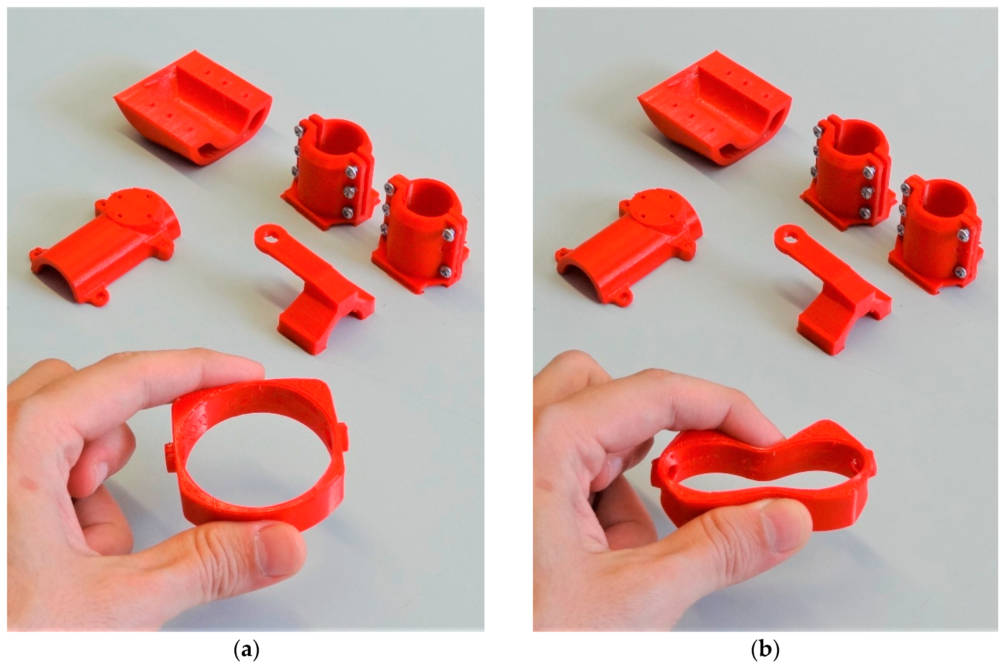
Figure 2 shows the 3D-printed parts that connect the arm to the servomotor and the servomotor to the mobile robot structure. Before using this elastic material, the original servomotors of the shoulder used to break due to force overload because they have to maintain a fixed arm orientation while compensating for all the weight and torque applied to the arms of the mobile robot by a person walking. This problem was solved adding elasticity to the servomotor support pieces which can have a wide range of infill density from 50 to 100%. This thermoplastic elastomer has been used previously as a passive suspension in the APR in order to reduce vibrations during the motion [
26].
3. Application as a Walk-Helper
This section describes the methodology developed in order to incorporate walk-helper capabilities in the APR. This capability is conceived as a functionality offered by the assistive robot. This functionality can be easily activated and deactivated by the user by interacting directly with the arms of the mobile robot. There are two different aspects when facing the development of this capability: the human–robot interaction, and the adaptive trajectory control.
3.1. General Idea of the Walk-Helper Application
The idea of extending the application of an APR as a walk-helper device is based on the use of the arms of the mobile robot as a dynamic support during a walking, similarly to the case of another person offering his arms as a walking support to other person. This basic functionality was initially developed as a simple procedure to manually guide the robot to a desired destination through the interaction with their arms. The realization of many different experiments with the APR revealed that an improved implementation of this manual guidance procedure could have application as a walk-helper device. The work and experimentation performed in this direction is presented in this paper.
The general idea of extending the application of the APR as a walk-helper is as follows: the user initiates the walk-helping operation by holding the arms on the mobile robot while the guidance of the walking trajectory is performed by interacting with the arms. The implementation of this general idea is based on the following steps: (1) the user must be located behind the mobile robot; (2) the interaction with one arm of the mobile robot can be used to rotate the APR according to the direction of the destination or to guarantee that the person is located behind the mobile robot; (3) the user must hold both arms and pull them back until reaching a comfortable holding position; (4) after three seconds the mobile robots detects the pulling of both arms, applies power to the servomotors in order to keep the arms in a fixed orientation (the arms are used as a holding support during the walking), and enters into the walk-helper operation; (5) the control of the walking trajectory is then performed by interacting with the arms of the mobile robot (changing the torque applied to each arm); (6) the onboard mobile robot sensors are used to detect and avoid obstacles [
27] in the walking trajectory; (7) the onboard mobile robot sensors can be used to supervise the direction of the walking [
28] in order to perform imperceptible trajectory corrections without user interaction, for example centering the path of the mobile robot when going through a door; (8) the operation as a walk-helper ends when no holding support or torque is detected in the arms.
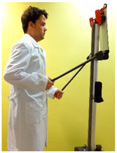
3.2. Walk-Helper Interaction
The human–robot interaction during a walk-helper operation is based on sensing the torque of the servomotor that provides movement to the arms of the mobile robot. This technique is commonly used in robotics, for example Menga et al. [
29] supervises the torque to control an exoskeleton for rehabilitation purposes. The walk-helper operation requires very simple steps: the user has to stand behind the robot, hold both robot arms, raise both arms until reaching a comfortable position for the walking, and hold them in this position during three seconds. The mobile robot detects this interaction by monitoring the torque and position of the servomotor of the shoulder. Then, the mobile robot enters in a walk-helper mode by maintaining the orientation of the arms and sensing torque interactions. At this point, the user can start the walking by using the arms of the mobile robot as a support. The control of the trajectory is accomplished by slightly changing the orientation of the arms of the mobile robot (raising or lowering).
Table 1 shows the different interactions proposed to drive the motion of the mobile robot while operating as a walk-helper. In this case, the interaction images shown in
Table 1 represent exaggerated user interactions. The APR is very sensitive to the interaction with the arms but most users tend to increment largely the holding force (or torque) applied to the arms as a way to try to walk faster or rotate faster. Therefore, the implementation of the joint of the shoulder was modified in accordance with this extreme usage by the inclusion of elastic supports pieces.
The mobile robot has programmed a basic set of motion commands: move forward, move backward, turn and rotate. In this paper, the difference between turn and rotate is based on who is considered the central axis of the action. When turning, the walk-helper considers the user as the center of the action, causing the robot to perform a circle around the user while maintaining the same distance between them. The rotate command considers the robot as the center of the action, meaning that the robot will rotate over itself. The possibility to turn is very useful when walking across small spaces but is only available in mobile devices with an omnidirectional motion system such as the APR.
The interaction of the user with the arms of the mobile robot is linearly deduced from the torque applied by the servomotors to maintain the orientation of the arms of the APR. This linear relationship has been established by a trial an error procedure but can be adapted in order to define different interaction sensitivities. The information of the interaction is used to dynamically control the displacement, orientation and velocity of the mobile robot while walking. The response of the walk-helper to an interaction is not instantaneous but is very predictable.
Table 2 shows this information in terms of relative angle and torque of the arms of the mobile robot just before and after performing each interaction.
The information of the interactions shown in
Table 1 and
Table 2 are correlated and complementary. In the standby action, the user holds the arms but without applying any torque. In the walk forward action, the user applies a forward force to both arms and then the walk-helper initiates a forward displacement with a proportional velocity. The turn right (or left) action is achieved by reversing the torque applied to one arm. In this case, if the forward velocity of the walk is zero the mobile robot turns to the right (or the left). However, if the forward velocity is not zero the mobile robots performs a slightly transversal or sideways movement combined with the forward displacement. These turning actions take full advantage of the omnidirectional capabilities of the mobile robot. The stop action is initiated by applying a back torque to both arms. The walk back action is also initiated by maintaining a back torque applied to both arms although this displacement is performed at very low velocity. This walk back operation has been implemented only for testing purposes but it is not recommended for this application because any obstacle behind the walk-helper will not be viewed by the user or the frontal onboard LIDAR and can cause a fall. Finally, the rotate right (or left) action is achieved by applying a reverse torque to both arms; the rotation is performed in the direction of the arm having a negative torque. The sensitivity of the interaction with the APR can be configured according the user requirements.
3.3. Adaptive Trajectory Control
The interaction with the mobile robot is used as a general indication of user’s intention. The walk-helper implementation also includes an adaptive trajectory control depending on the objects detected around the mobile robot which can be considered as a simplified implementation of the nearness diagram navigation (DN) proposed by Minguez et al. [
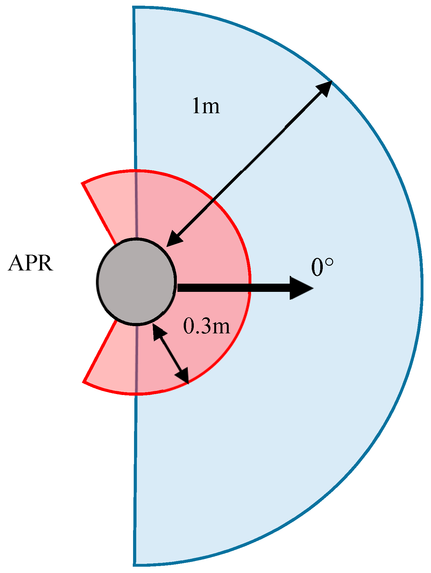
28]. Both the DN and the proposed adaptive trajectory control are based on the processing of data retrieved by an onboard LIDAR. However, the goal of the proposed adaptive trajectory control is limited to ensure the safety of the walking trajectory and also to provide smooth trajectory corrections in complex environments such as narrow spaces or doorways. To this end, the mobile robot analyses the point cloud information retrieved by the LIDAR to generate a two-dimensional representation of its surroundings in order to identify and avoid obstacles and to align the trajectory with the elements of the environment. The mobile robot automatically integrates the information of the point cloud and the user interaction in order to find an optimal path that best matches the direction of the current displacement. As a consequence, the mobile robot constantly performs slight trajectory corrections to align the trajectory according to hallways or walls and to automatically avoid objects in the current trajectory of the walking. This adaptive trajectory control divides the area in front the mobile robot into two different circular search areas (
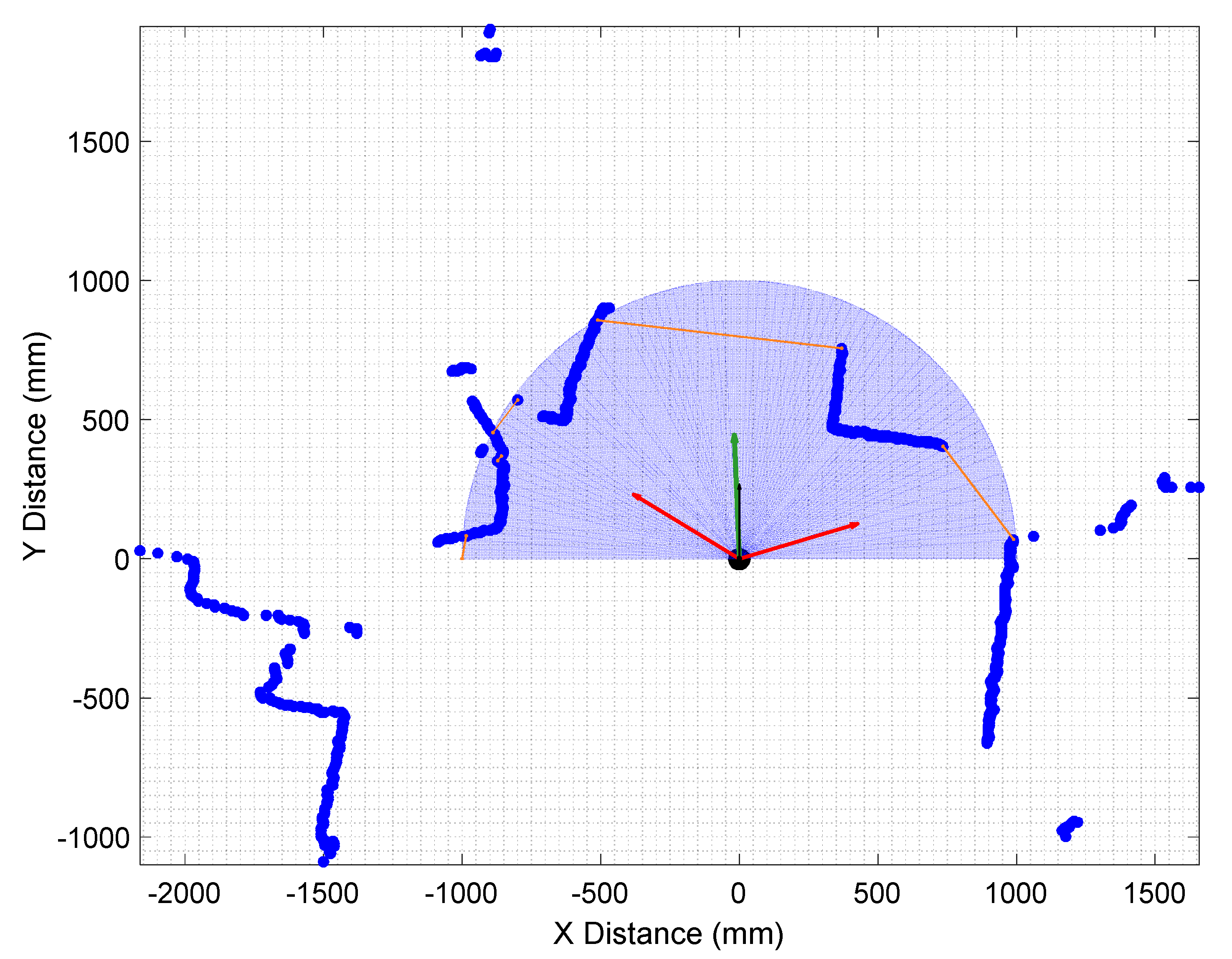
Figure 3). The red area represents the zone considered as “dangerous”, covering a radius of 0.3 m 30 and an angle of 270° ([−135°, +135°] where 0° corresponds to the front of the robot). The blue area represents the “influence” zone that covers a radius of 1 m and an angle of 180° ([−90°, +90°]).
The dangerous zone defines the minimum distance allowed between the robot and the nearest obstacle. If anything is detected in the dangerous zone the mobile robot automatically stops; after that, the robot will limit its movements to rotations and lateral displacements until the obstacle is cleared or the user changes the orientation of the walking into a clear direction. The influence zone is used to determinate free spaces where the robot could pass through. The free spaces are detected by unifying discontinuous blank spaces between laser points inside the interaction area (escape areas). After that, the robot calculates the angles that lead to each one of the detected available paths (escape vectors). Finally, the robot identifies and follows the escape vector that best matches the current direction of walking trajectory.
Figure 4 shows an example situation where the mobile robot has to adapt its path in order to avoid colliding with the corner of a wall. In this example, the robot identifies three potential escape vectors (red arrows) that would lead the robot into a navigable area. After computing the angle difference between the potential escape vectors and the current direction of motion, the mobile robot identifies the route that most likely the user wants to follow (green arrow) and performs the required adjustments to the current trajectory of the robot. This analysis is repeated when the LIDAR provides new raw data; every 100 ms approximately. As an additional security measure, the maximum speed of the robot is also conditioned by the distance to the nearest detected obstacle. In the future, the robustness of the collision avoidance procedure will be revised by taking into account the uncertainty of the environment and the uncertainty of the motion of the robot [
30].
The advantage of this walk-helper implementation is the use of the kinematic model of the omnidirectional motion system [
24] to execute precise and complex displacements without user intervention. This automatic trajectory correction largely minimizes the number of corrections that the user must perform in order to reach the desired destination.
4. Experimental Results
The experimental results presented in this paper have been obtained by the authors, testing the APR as a walk-helper in different operation conditions and environments. The general objective was to test the intuitive user interface and the adaptive trajectory control of the APR during its application as a walk-helper. During the tests the LIDAR raw data, the trajectory measured with the encoders of the wheels, and the information of the servomotors was logged in order to enable the representation of the walking trajectory. The experiments have been developed in a simulated household domain and consists in using the walk-helper while conducting simple ordinary tasks such as preparing a simple meal in the kitchen, and going to the living room. These activities were repeated several times in a random sequence in order to fully test the walk-helper capabilities.
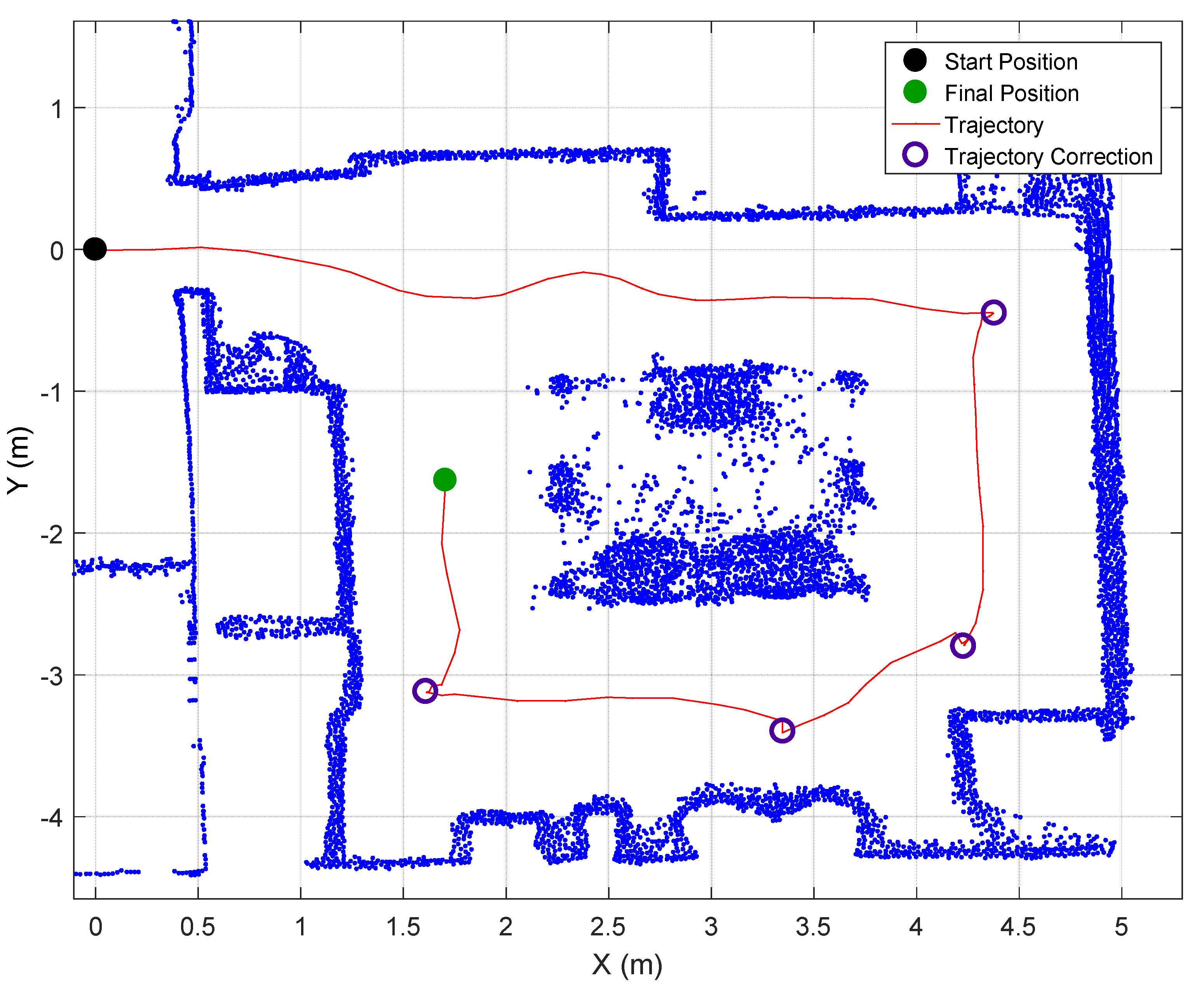
Figure 5 shows the reconstructed walking trajectory in the case of conducting a displacement in a simulated kitchen with narrow walking areas. In this case the difficulty is that in the center of the room there is a table and several chairs with thin legs that are barely detected by the LIDAR of the walk-helper. At this point, please note that
Figure 5 shows a point-cloud reconstruction based on the superposition of a large number of LIDAR scans so this is why a lot of points appear under a table because a single scan only shows a small amount of points depending on the proximity to the legs of the table and the chairs.
Figure 5 shows that the trajectory of the walk-helper when entering the room is oscillating because only the legs of the table are detected as a near obstacle. The trajectory of the walk-helper becomes less oscillating when the legs of the chairs under the table are also detected. Finally,
Figure 5 also shows that only 4 trajectory corrections are needed to complete the exploration of the simulated kitchen. In general, the possibility of performing either a rotation or a turn has simplified the control of the walk-helper when walking around big furniture objects such as a table.
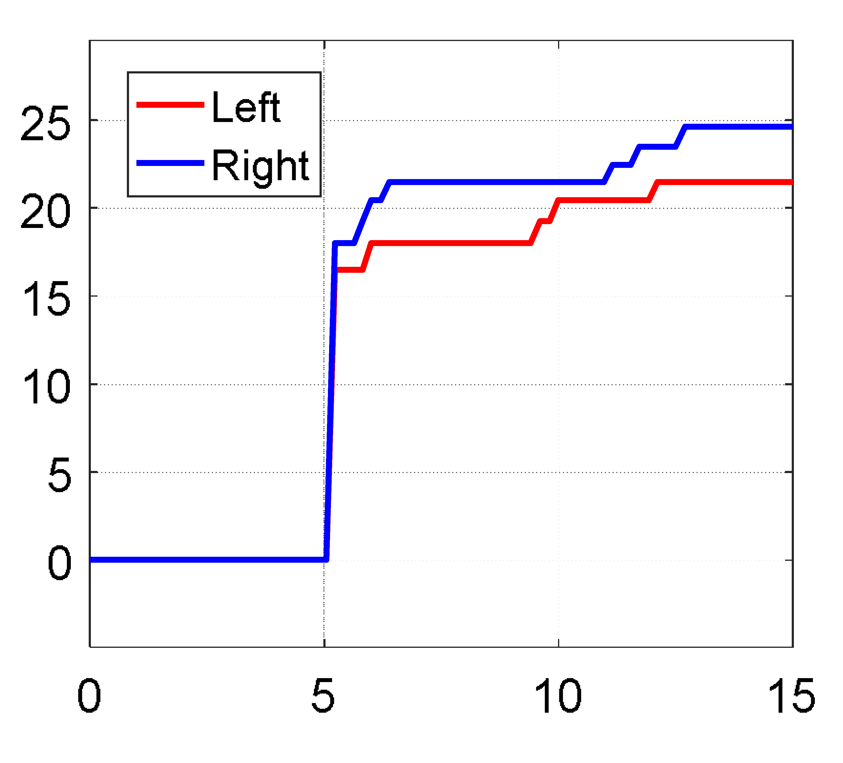
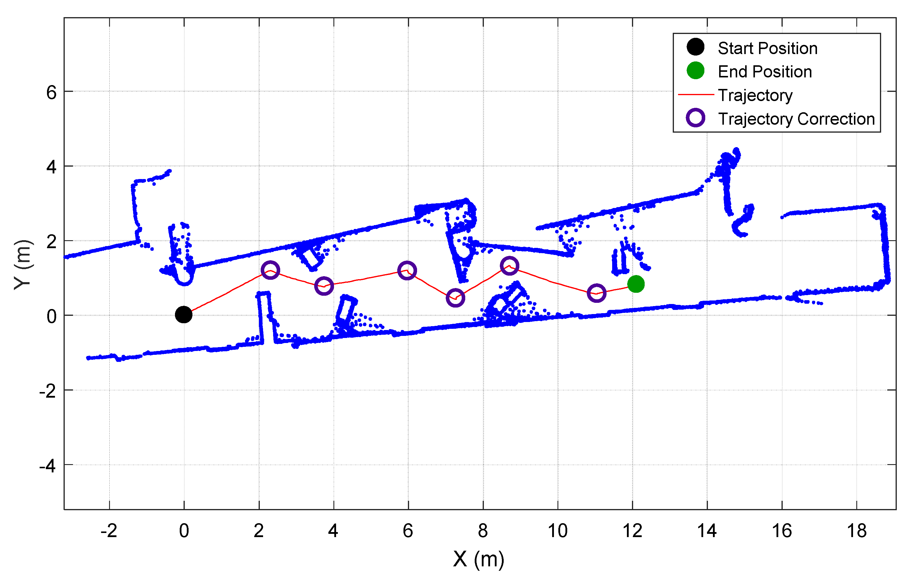
Figure 6 shows the trajectory registered when conducting a walk along a 15 m long corridor filled with different obstacles partially blocking the way. In this case the walk-helper was configured with the adaptive correction system disabled and six trajectory corrections were required to reach the final destination. Alternatively,
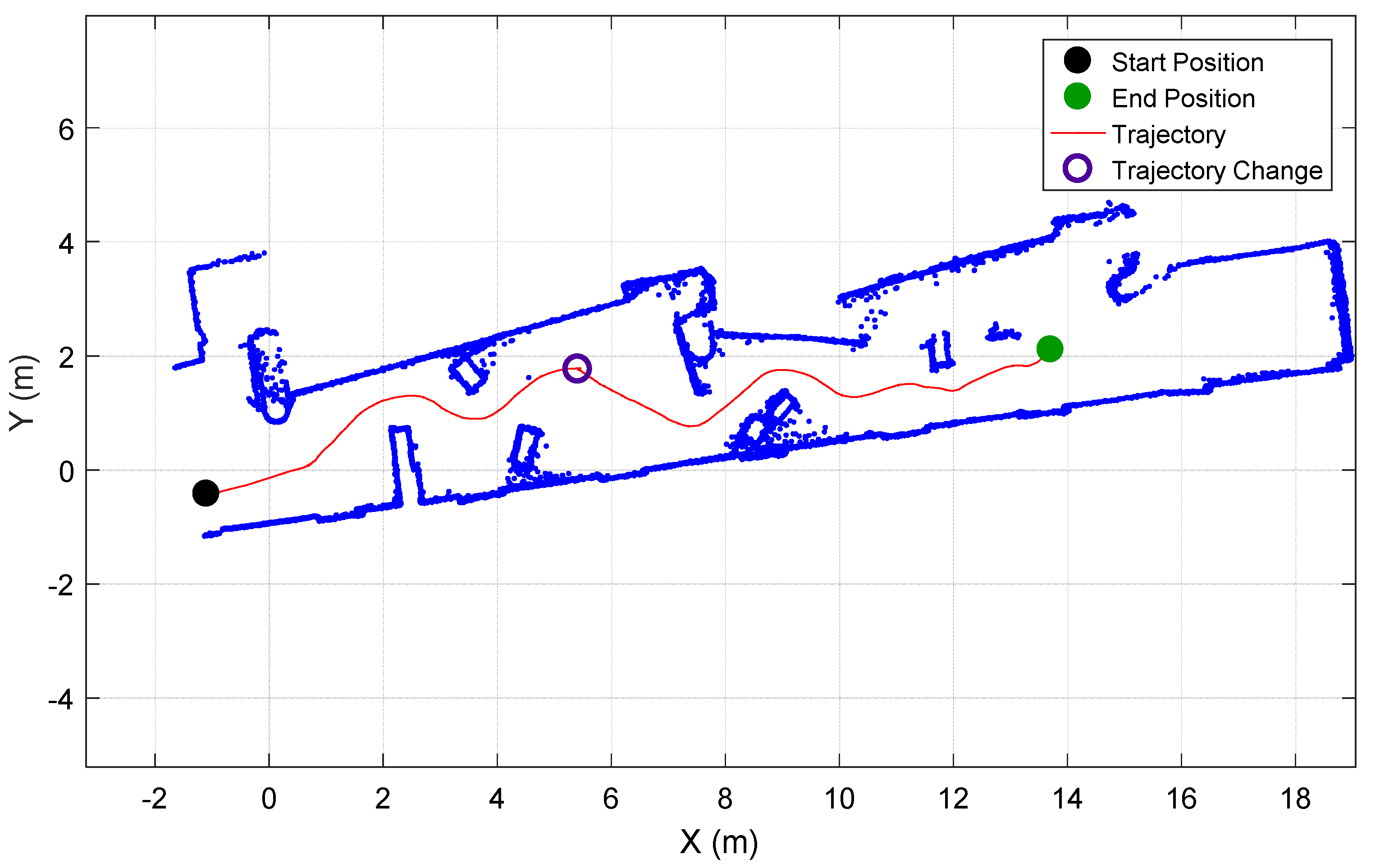
Figure 7 shows an example of the trajectory registered in the same corridor with the walk-helper configured with the adaptive correction system enabled (which is the normal operation of the walk-helper). In this case the walk-helper used the information gathered by the LIDAR to perform small trajectory corrections to automatically guide the walk while keeping the distance with surrounding obstacles so only one trajectory correction was required to reach the destination and complete the displacement.
Comparatively,
Figure 6 shows a trajectory composed by a sequence of straight displacements and rotations while
Figure 7 show an almost continuous curved trajectory that slightly avoids the obstacles in the path of the displacement. Similar results were obtained when repeating this displacement. In general, the number of trajectory corrections required to complete the walking displacement was between eight and five when the adaptive correction system of the walk-helper was disabled while the trajectory followed by the walk-helper with the adaptive correction system enabled was always very similar, requiring only one trajectory correction (or 0 in case of waiting a few seconds before interacting with the mobile robot). In average, the walk-helper required around 250 s and six trajectory corrections to complete a forward walking displacement when the adaptive trajectory control was disabled and only 180 s (28% less) and one trajectory change (83% less) when the walk-helper was operated with the adaptive control enabled. This improvement agrees with the results obtained in other extensive experiments such as the performed by Urdiales et al. [
31], who stated that humans driving a wheelchair along a corridor were less efficient than humans driving automatic robotized wheelchairs.
5. Conclusions
This paper presents the extension of the application of an Assistant Personal Robot as a walk-helper tool. This application has been conceived to provide an additional functionality useful to support people while they walk. In this walk-helper application, the user initiates the walking by holding the arms of the mobile while the control of the trajectory is performed by interacting with the arms of the mobile robot. The walk-helper includes a simple but effective adaptive trajectory control that slightly corrects the walking trajectory according to the surrounding obstacles and free spaces where the robot could pass through. This adaptive trajectory control takes full advantage of the omnidirectional motion capabilities of the mobile robot in order to minimize the number of manual trajectory corrections required to complete an assisted walking.
This paper also presents the experimental results conducted by the authors in two simulated home domain environments. The walk-helper application has been tested while simulating a displacement in a kitchen showing that the partial detection of the legs of the tables generates slightly oscillating trajectories. The walk-helper application has been also tested in a long corridor filled with non-blocking obstacles and with the automatic adaptive trajectory control enabled and disabled. In this case, the comparison of the walking trajectory indicates that an adaptive trajectory control can contribute to reducing the number of trajectory corrections required to complete a walking displacement.
Therefore, the conclusion is that a multipurpose assistant mobile robot with an omnidirectional motion system can be proposed also as a walk-helper device as a way to provide a dynamic physical support to people while they walk. However, it is important to note that the current design of the mobile robot used in this paper to implement the walk-helper application has originally a reduced surface in contact with the floor so it could not provide enough stability to users with walking mobile limitations.
Future work will be focused in the analysis of the use of the walk-helper as a tool to promote unsupervised walking exercises in case of no mobility limitations and in the design and development of extensive tests with potential users.


