Article

A Toolbox for the Analysis of the Grasp Stability of Underactuated Fingers †

by
Giovanni Antonio Zappatore
1,
Giulio Reina
2,* and
Arcangelo Messina
2
1
BionIT Labs Company, Via A. Bortone, 73100 Lecce, Italy
2
Dipartimento di Ingegneria dell’Innovazione, Università del Salento, Via Arnesano, 73100 Lecce, Italy
*
Author to whom correspondence should be addressed.
This paper is an extended version of our paper published in Zappatore, G.; Reina, G.; Messina, A. A proposed software framework for studying the grasp stability of underactuated fingers. In Proceedings of the 4th IFToMM Symposium on Mechanism Design for Robotics, Udine, Italy, 11–13 September 2018; pp. 202–210.
Robotics 2019, 8(2), 26; https://doi.org/10.3390/robotics8020026
Submission received: 29 December 2018 / Revised: 22 March 2019 / Accepted: 28 March 2019 / Published: 6 April 2019
(This article belongs to the Special Issue Mechanism Design for Robotics)

Abstract

:
In the design of humanoid robotic hands, it is important to evaluate the grasp stability, especially when the concept of underactuation is involved. The use of a number of degrees of actuation lower than the degrees of freedom has shown some advantages compared to conventional solutions in terms of adaptivity, compactness, ease of control, and cost-effectiveness. However, limited attention has been devoted to the analysis of grasp performance. Some specific issues that need to be further investigated are, for example, the impact of the geometry of the fingers and the objects to be grasped and the value of the driving mechanical torques applied to the phalanges. This research proposes a software toolbox that is aimed to support a user towards an optimal design of underactuated fingers that satisfies stable and efficient grasp constraints.

Graphical Abstract

1. Introduction

In the last few years, increasing interest has been devoted towards compliant and underactuated hands as a compact, reliable, and flexible grasping solution in manipulation applications [1,2]. However, relatively limited attention has been given to the development of simulation tools that address the specific challenges connected with underactuated grasping [3]. Notable examples are GraspIt! [4] and OpenGrasp [5]. Both simulators allow a set of common objects and various types of grippers to be analyzed, but they are not well suited for grasp stability analysis, especially when underactuated architectures are considered. Other recent efforts that address the specific design of under-actuated hands include [6], whereas SynGrasp [7] is a MATLAB toolbox for grasp analysis of fully or underactuated robotic hands. Finally, in [8], the Yale-CMU-Berkeley (YCB) object and model set is presented that is intended to be used to facilitate benchmarking in robotic manipulation, prosthetic design, and rehabilitation research.
This paper introduces a simulation toolbox that the authors developed during their current efforts at BionIT Labs towards an efficient design of Adam’s Hand: a transradial myoelectric prosthesis that uses a highly underactuated mechanism, composed of 14 differential stages actuated by a single motor −15 degrees of freedom (DOFs), 1 degree of actuation (DOA) [9]. The underactuation among the fingers is obtained by symmetrically stacking five bevel gear differential stages, while the underactuation within each finger is obtained by stacking serially two differential idler pulleys per finger. A functional scheme of the designed mechanism is shown in Figure 1, while a more in-depth analysis of the proposed mechanism can be found in [10,11]. This paper extends the study, preliminary presented by the authors in [12], on the contact forces generated by the underactuated fingers during enveloping grasps. The overall goal is to optimize their features by maximizing the contact conditions for which a stable grasp can be achieved. As explained in the following section, these contact situations are identified by a combination of phalanx flexion/extension angles and contact points of the phalanges with the object to be grasped. In order to simplify the analysis that involves a high number of variables, a software is presented in Section 4 to support a user during the design stage. The software framework, available upon request, is developed in the Mathematica environment, which is a very powerful symbolic language and well-established in the scientific and industrial world. Mathematica programming environment allows to easily exploit other specific tools and built-in math functions enabling the exploration of multiple approaches and the integration with other analysis tools, e.g., statistical processing of experimental data, optimization, dynamic models, and simulations.

2. General Static Model

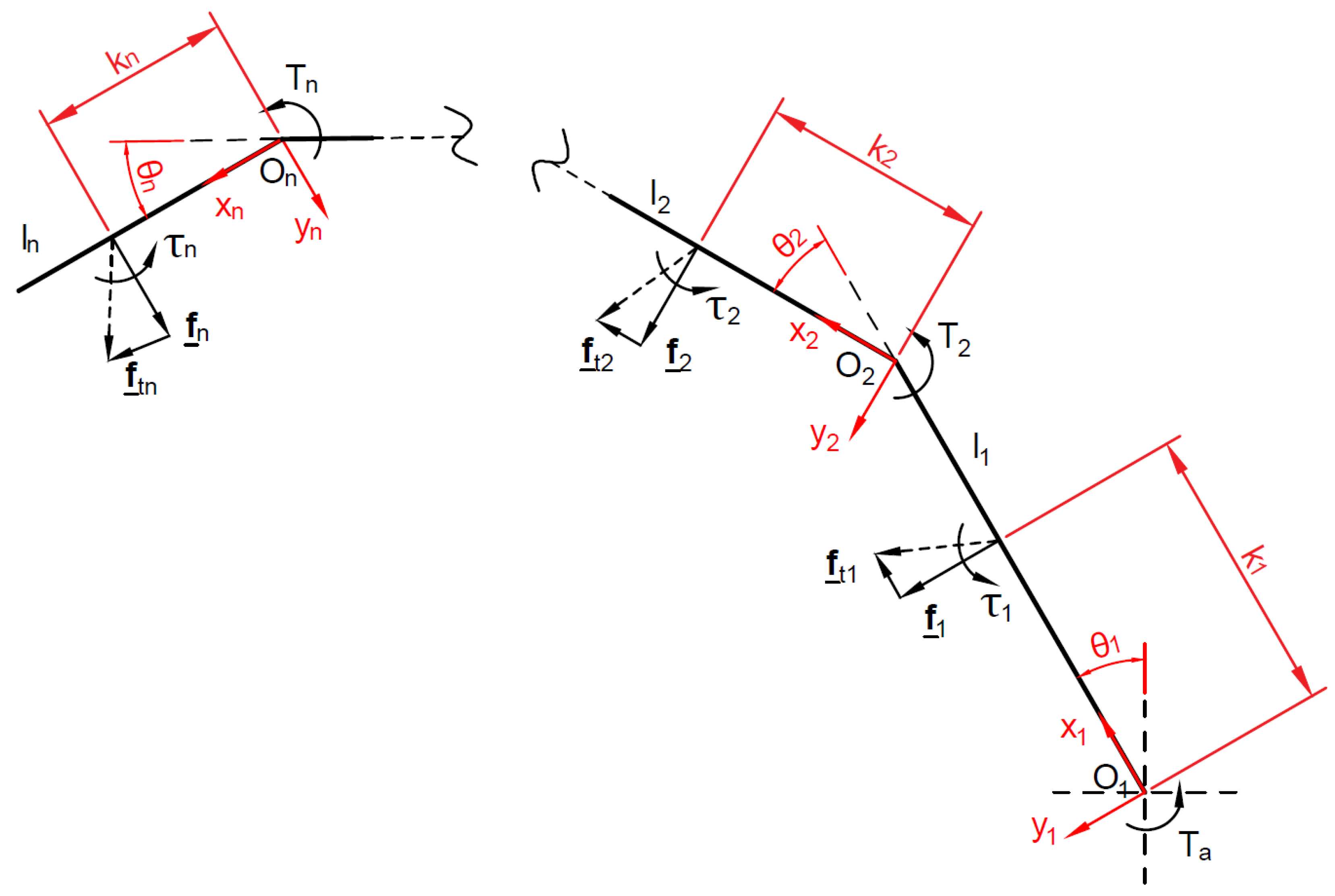
Drawing on [13], the model of underactuated finger used in this paper is shown in Figure 2. The following assumptions hold: the finger motion is planar (no abduction/adduction), and all the n phalanges, which are driven by a single actuator, are linked through revolute joints. Equating the input and output virtual powers of this system, one obtains:
t T ω a = i = 1 n ξ i ζ i
where:
  • t is the input torque vector exerted by the actuator ( T a ) and the springs located between the phalanges ( T 2 , , T n ):
    t = T a T 2 T n T
  • ω a is the corresponding joint velocity vector:
    ω a = θ ˙ a θ ˙ 2 θ ˙ n T
    where θ i is the ith joint variable.
  • ξ i is the twist of the ith contact point on the ith phalanx (assuming one contact per phalanx) with a corresponding wrench ζ i , and the operator “∘” stands for the reciprocal product of screws in the plane.
It can be shown that:
ξ i ζ i = f T ( J θ ˙ ) = f T ( J T ω a )
where:
  • f T is the vector of the resultant of contact forces, f i , normal to phalanx 1 , , n :
    f = f 1 f 2 f n T
  • J is the Jacobian Matrix, a n × n square matrix which depends only on the location of the contacts k i on the phalanges and their relative orientation r i j T , their length l i and the friction coefficients μ i and η i :
    J = k 1 + η 1 0 0 r 12 T ( x 2 μ 2 y 2 ) + η 2 k 2 + η 2 0 r 1 n T ( x n μ n y n ) + η n r 2 n T ( x n μ n y n ) + η n k n + η n
  • T is the Transmission Matrix, a n × n square matrix which depends on the stage transmission ratios x i of the mechanism used to propagate the actuation torque to the phalanges:
    T = 1 x 1 x 2 x 1 x 2 x 3 i = 1 n x i 0 n 1 T I n 1
    where I n 1 and 0 n 1 T are the identity matrix and the zero vector of dimension ( n 1 ) .
Then, considering Equations (1) and (4), the equilibrium of virtual power for the system results:
t T ω a = f T ( J T ω a )
from which one obtains a useful relationship between the actuator torques and the contact forces:
f = J T T T t
It should be noted that a n-output m-input underactuated mechanism requires n m springs in order to be statically determined. For this reason, depending on the mechanism design, it is possible that a torsion spring will be required also in the base joint O 1 . In this case, matrix J remains the same, while vector t and matrix T 1 respectively become:
t = T a T 1 T 2 T 3 T
T 1 = T = 1 x 1 x 2 x 1 x 2 x 3 i = 1 n x i I n
where I n is the identity matrix of dimension n, and T is now a rectangular matrix of dimensions ( n + 1 ) × n . Equation (9) in this case becomes:
f = J T T T t
and the forces obtained are the same calculated in absence of the base joint spring, except for f 1 , which contains the additional term T 1 1 k 1 + η 1 (and this holds for any number of phalanges). This result represents the most general one, since if T 1 = 0 also f 1 equals the one previously obtained. For this reason, from now on, matrices J (Equation (6)) and T (Equation (11)) and vector t (Equation (10)) will be used to optimize the fingers design using Equation (12).

2.1. Impact of Phalanx Thickness

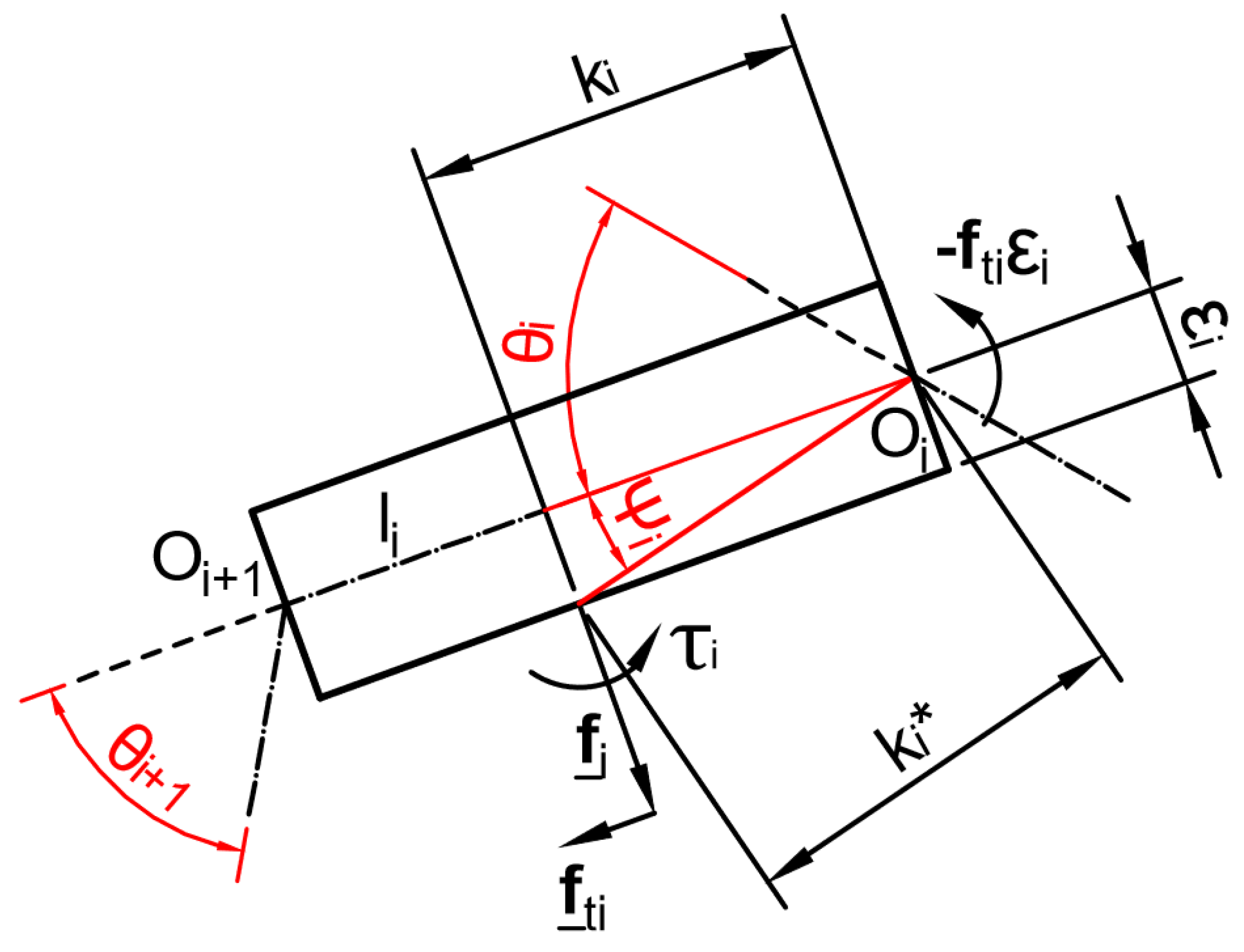
As can be seen in Figure 3, when the ith phalanx thickness ϵ i is not negligible the angle θ i should be augmented by the quantity:
ψ i = arctan ϵ i k i
and the contact location k i should be shifted by
k i = k i 2 + ϵ i 2
In addition, when friction is non-zero, the equilibrium locus changes due to the moment generated by the tangential force, which can be modelled using the coefficient η i : the tangential force produces a moment about O i equal to f t i ϵ i . This moment can be seen as a wrench with the same normal and tangent forces and a torque τ i equal to the case of a zero thickness phalanx. Therefore, one gets τ i = η i f i = f t i ϵ i = f i μ i ϵ i , thus the equivalent instantaneous rolling friction coefficient is η i = ϵ i μ i . The latter coefficient must be added to the previous value of η i describing the contact friction (even if it is zero). This change can be reflected directly into the matrix J to obtain the new force expressions.

2.2. Positive Definiteness of the Forces

Given a set of geometric parameters, Equation (9) or (12) provides the contact configurations defined by the pair ( k , θ )
k = k 2 k 3 k n and θ = θ 2 θ 3 θ n
that ensure full positiveness of the vector f . The set of these contact situations corresponds to the stable part of the space spanned by the contact situations pair ( k , θ ) which are referred to as the space of contact configurations or grasp-state space. Stable grasps correspond to contact situation pairs for which the vector f has no negative component, that is, the phalanges in contact with an object have a positive (or zero) contact forces. The other phalanges that are not in contact with the object must correspond to zero contact forces. It should be underlined that this approach tries to characterize the finger itself, independently from the object being grasped.
It should be also considered that the grasps requiring all the phalanges correspond only to a subset of all the possible grasps: fewer-than-n-phalanges grasps can also be stable if each phalanx which contacts the object has a strictly positive contact force and each phalanx not in contact with the object has a null contact force.

3. Contact Forces Writing for the Proposed Finger Mechanism

The general equations presented in Section 2 are written for the scheme proposed in Figure 1, for both the two-phalanx thumb ( I ) and for the four three-phalanx fingers, from index ( I I ) to pinkie ( V ) . As mentioned in Section 1, the prosthetic hand under study features n = 15 DOFs that are actuated by just m = 1 DOA, so n m = 15 1 = 14 springs are required to solve the static equilibrium equations. Due to symmetry considerations, these springs have to be located in all the joints of each finger (three springs for finger I I ÷ V and two springs for finger I), so that also the base joint ( O 1 ) of each finger will be linked through a spring to the fixed palm.

3.1. Two-Phalanx Finger

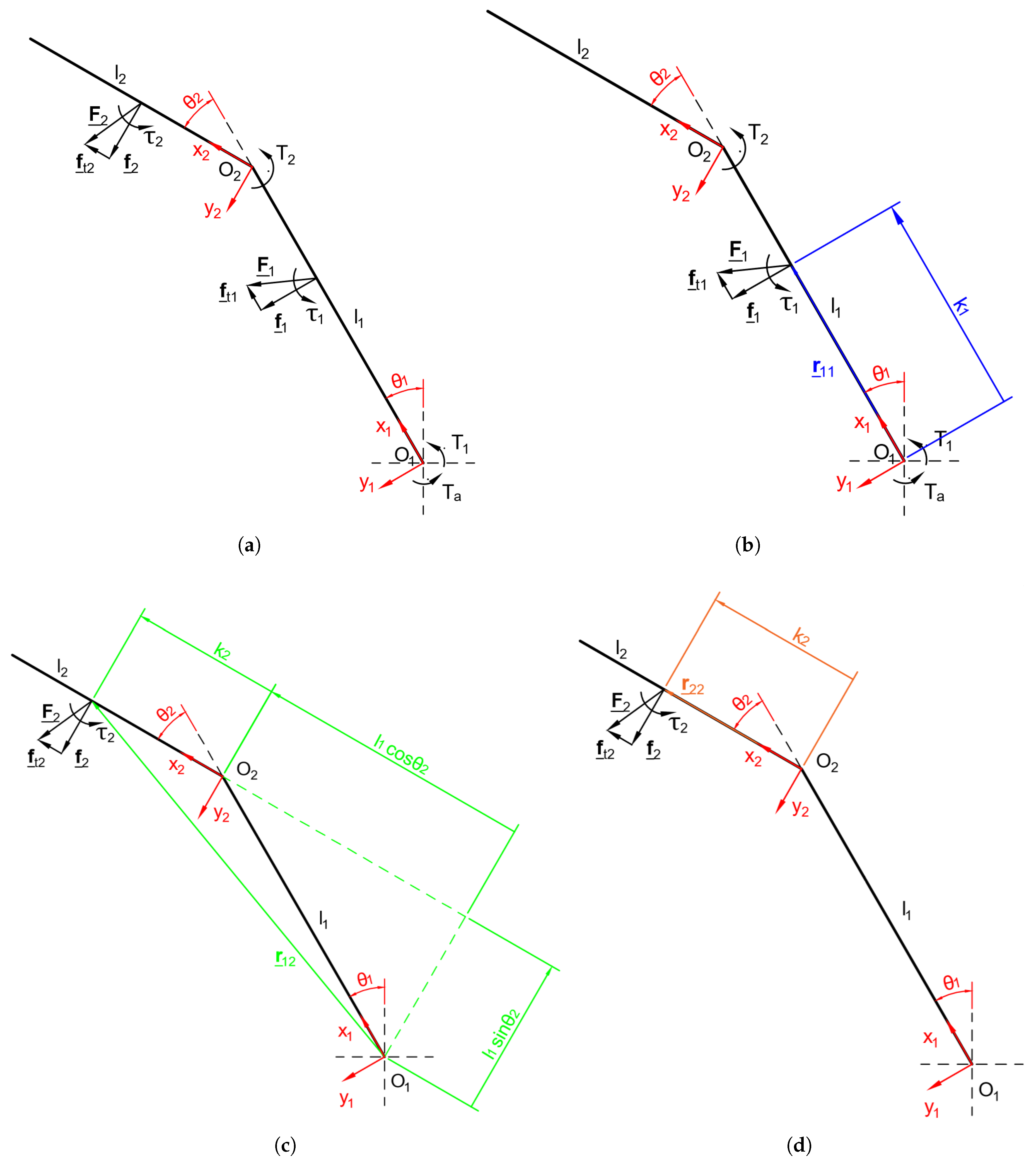
Three DOFs are assigned to the thumb, corresponding to proximal and distal phalanges flexion/extension and to metacarpus abduction/adduction. These members are interconnected via three revolute joints. A torsional spring that is positioned in each joint, which links the phalanges, the metacarpus, and the palm. Since the analysis carried out in Section 1 does not consider out-of-the-flexion-plane movements, in the following analysis the metacarpus motion is constrained so that the thumb results as composed only by the proximal and the distal phalanges. Whereas this approximation subtracts generality to the analysis, it should be considered that many grasp typologies can be obtained with the metacarpus fixed relatively to the palm. The model of the thumb is presented in Figure 4a.
Both flexion/extension of the two phalanges and abduction/adduction of the metacarpus are driven by the torque deriving from the bevel gear differential stage 4, as shown in Figure 1.
Matrix J I according to Equation (6) is given by:
J I = k 1 + η 1 0 k 2 + l 1 ( cos θ 2 μ 2 sin θ 2 ) k 2 + η 2
The physical meaning of J I is showed in Figure 4b–d.
When phalanx thickness ϵ i is taken into account, the finger model becomes that shown in Figure 5a, as discussed in Section 2.1.
Matrix J I gets:
J I = k 1 + η 1 0 k 2 + l 1 ( cos θ 2 μ 2 sin θ 2 ) + μ 2 η 2 k 2 + η 2
since vectors r k i in this case acquire another component proportional to phalanx thickness ϵ i along y i axis, as shown in Figure 5b–d. This matrix represents a generalization of the matrix reported in Equation (16) for ϵ i 0 ( i = 1 , 2 ). Therefore in the following analysis, matrix J I will be derived from Equation (17).
Matrix T I and vector t I can be obtianed respectively from Equations (7) and (10):
T I = 1 x 12 , I 1 0 0 1
t I = T a , I T 1 , I T 2 , I T
with x 12 , I being the transmission ratio between the base and the middle idler pulleys and T a , I the torque exerted by one of the two sun gears of the bevel gear differential Stage 4. Moreover:
T h , I = K h , I ( π / 2 θ h , I + Z h , I ) if   spring   opposes   hand   opening K h , I ( θ h , I + Z h , I ) if   spring   opposes   hand   closing
with K h , I being the spring stiffness and Z h , I the spring preload for joints h = 1 , 2 of the thumb.
The contact forces obtained from Equation (12) are then:
f 1 = ( T 1 + T a ) 1 k 1 + η 1 ( T 2 + T a x 12 , I ) [ k 2 + η 2 + μ 2 ϵ 2 + l 1 ( cos θ 2 μ 2 sin θ 2 ) ] ( k 1 + η 1 ) ( k 2 + η 2 ) f 2 = ( T 2 + T a x 12 , I ) 1 k 2 + η 2
Neglecting friction ( μ i = η i = 0 i ) and considering x 12 , I = 1 , these equations become much simpler:
f 1 = ( T 1 + T a ) 1 k 1 ( T 2 + T a ) k 2 + l 1 cos θ 2 k 1 k 2 f 2 = ( T 2 + T a ) 1 k 2
The grasp is stable only if f i > 0 for i = 1 , 2 . By studying the contact situations defined by the pair ( k 2 , θ 2 ) for a determined set of geometric, static, and dynamic parameters (phalanx length and thickness, friction coefficients, springs stiffness and preload, actuation torque, …) the portion of the grasp-state space in which all the forces are positive can be obtained. By varying the design parameters, this portion can be maximized in order to ensure a stable grasp for the largest number of contact situation achievable.

3.2. Three-Phalanx Fingers

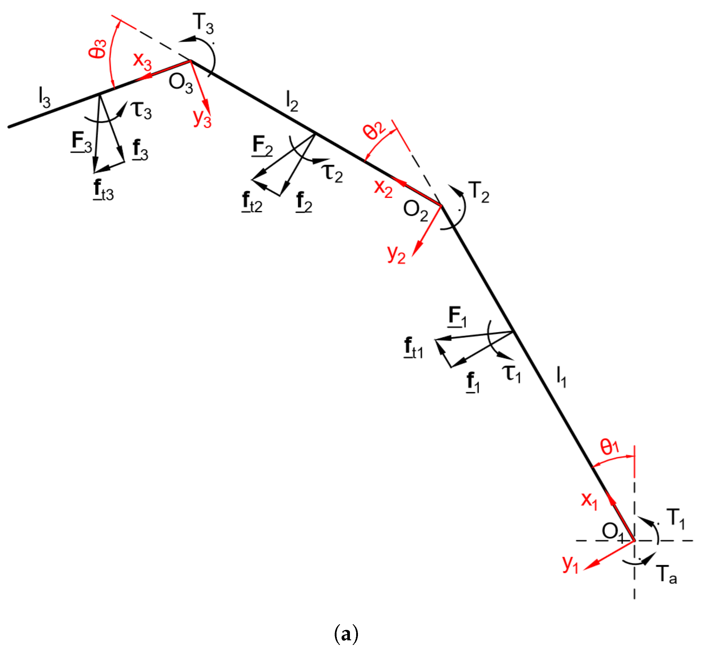
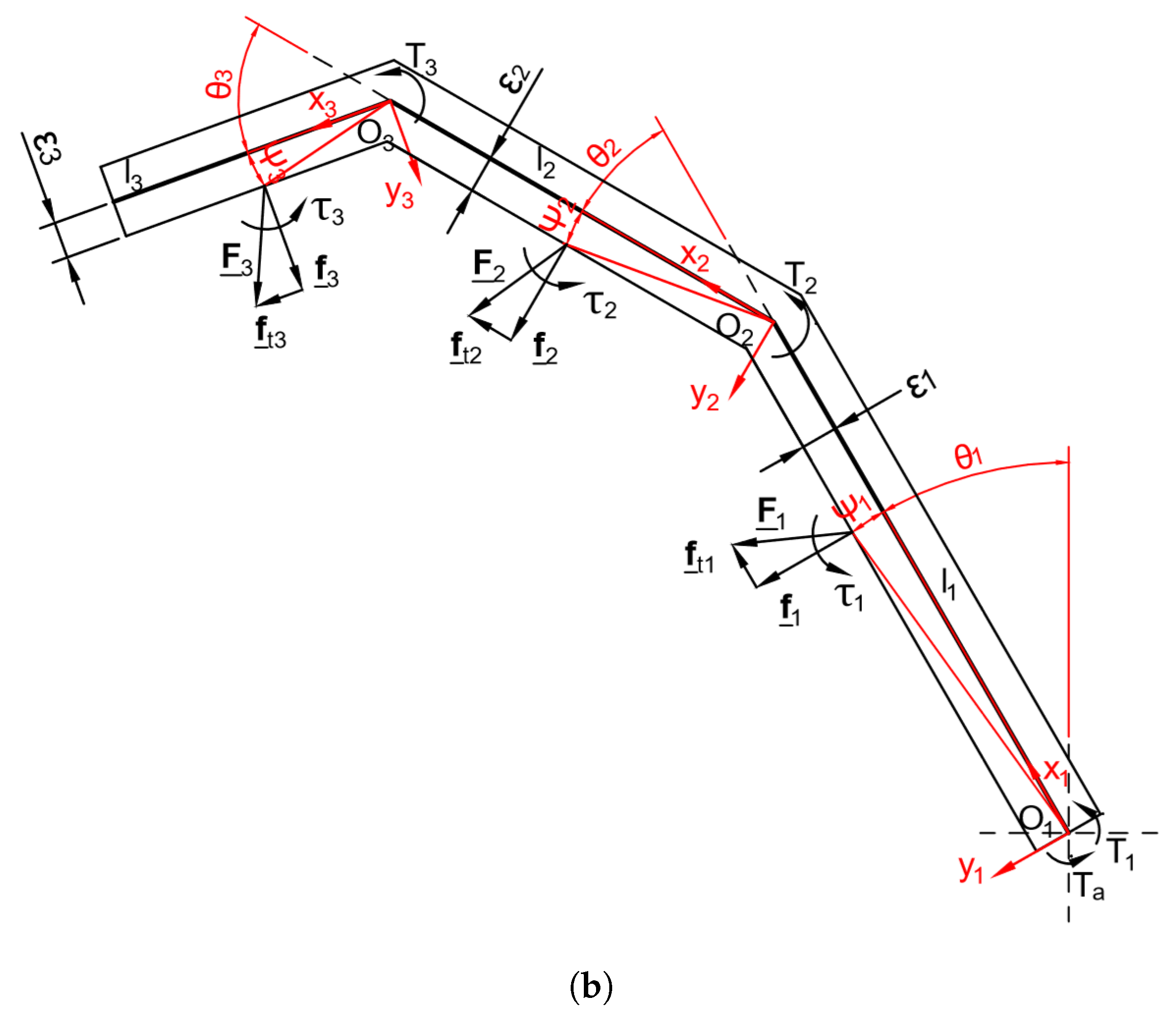
In this case, three DOFs are assigned to each one of fingers I I ÷ V . They all feature three phalanges linked through three revolute joints among them and to the fixed palm. A torsional spring is located in each joint. The model of this finger is presented in Figure 6a. The model is modified as shown in Figure 6b when phalanx thickness is not negligible.
Each finger is driven by the torque delivered by the bevel gear differential stages 2 (fingers I I and I I I ) or 3 (fingers I V and V), as shown in Figure 1. Considering the same assumptions made for the two-phalanx finger, the contact forces obtained from Equation (12) are:
f 1 = ( T 1 + T a ) 1 k 1 + η 1 ( T 2 + T a x 12 ) [ k 2 + η 2 + μ 2 ϵ 2 + l 1 ( cos θ 2 μ 2 sin θ 2 ) ] ( k 1 + η 1 ) ( k 2 + η 2 ) + ( T 3 + T a x 12 x 23 ) [ μ 2 ϵ 2 + l 1 ( cos θ 2 μ 2 sin θ 2 ) ] [ k 3 + η 3 + μ 3 ϵ 3 + l 2 ( cos θ 3 μ 3 sin θ 3 ) ] ( k 1 + η 1 ) ( k 2 + η 2 ) ( k 3 + η 3 ) ( T 3 + T a x 12 x 23 ) l 1 [ cos ( θ 2 + θ 3 ) μ 3 sin ( θ 2 + θ 3 ) ] ( k 1 + η 1 ) ( k 3 + η 3 ) f 2 = ( T 2 + T a x 12 ) 1 k 2 + η 2 ( T 3 + T a x 12 x 23 ) [ k 3 + η 3 + μ 3 ϵ 3 + l 2 ( cos θ 3 μ 3 sin θ 3 ) ] ( k 2 + η 2 ) ( k 3 + η 3 ) f 3 = ( T 3 + T a x 12 x 23 ) 1 k 3 + η 3
Again, neglecting friction ( μ i = η i = 0 i ) and considering x 12 = x 23 = 1 , these equations become much simpler:
f 1 = ( T 1 + T a ) 1 k 1 ( T 2 + T a ) k 2 + l 1 cos θ 2 k 1 k 2 + ( T 3 + T a ) [ k 3 l 1 cos θ 2 + l 1 l 2 cos θ 2 cos θ 3 k 2 l 1 cos ( θ 2 + θ 3 ) ] k 1 k 2 k 3 f 2 = ( T 2 + T a ) 1 k 2 ( T 3 + T a ) k 3 + l 2 cos θ 3 k 2 k 3 f 3 = ( T 3 + T a ) 1 k 3
The grasp is stable only if f i > 0 for i = 1 , 2 , 3 . As for two-phalanx finger, by studying the contact situations defined by the pair k 2 k 3 , θ 2 θ 3 one can obtain the portion of the grasp-state space in which all the forces are positive.

4. Proposed Software

The software toolbox provides a useful tool to simplify the grasp-state space analysis and parametric optimization. It was developed under the Wolfram Mathematica environment [14]. The graphical user interface (GUI) is shown in Figure 7. It consists of four main areas. The first row (2-phalanx finger) and the second row (3-phalanx finger) refer to the finger geometric parameters explained in the previous sections; the third row collects the parameters relative to the target object (position, size, shape), other parameters used to define the limits of the grasp-state space, and the constraints on the normal and tangential contact forces both for two- and three-phalanx fingers; the fourth row includes the graphs that represents the grasp-state space ( k 2 , θ 2 ) and the scheme of the two-phalanx finger on the left side, whereas two graphs representing the grasp-state spaces ( θ 2 , θ 3 ) and ( k 2 , k 3 ) and the scheme of the three-phalanx finger are shown on the right side. Each subsection of the GUI is explained in more detail in the remainder of the paper.
  • Sections 1 and 2—Phalanx length and semi-thickness
    Phalanx lengths can be set by matching those of the human hand, using standard biomechanical measurements ([15]), as shown in Table 1. Phalanx thickness, instead, has been set considering the size of the mechanical transmission, in order to simplify the following design validation and due to the lack of standard biomechanical measurements in the Literature.
    Note that the software requires as input the phalanx semi-thickness.
  • Sections 3, 4, and 5—Springs presence, direction, stiffness, and preload
    The software foresees the adoption of a spring in each joint; when a joint (e.g., O 1 , O 2 , O 3 ) is checked, the rotary spring is activated and the relative stiffness and preload can be set, otherwise the spring is neglected. The user can also choose if the spring opposes opening or closing of the prosthetic hand.
    As stated before, the proposed mechanism requires a spring in each joint of the finger in order to obtain a statically determined finger.
  • Section 6—Friction coefficients
    The user can choose whether or not to consider friction by checking or unchecking the relative button; in the first case the value of friction coefficients μ i and η i ( i = 1 , 2 , 3 ) can be set. These values depend on the material of the object–finger contact: typical values are 0.8 for a steel–steel contact and 1 ÷ 4 for solid–rubber (in both cases clean and non-lubricated [16]). As a matter of fact, it should be considered that robotic finger surfaces can be coated with a rubber-like layer to increase friction or indirectly through the use of a tactile sensing device.
    It should be also noted that for a given value of μ i , s t a t i c two values of μ i should be considered, each corresponding to one sliding direction, i.e., μ i = + μ i , s t a t i c or μ i = μ i , s t a t i c .
  • Section 7—Torque and transmission ratios
    The base joint actuation torque T a must be provided in order to calculate contact forces. Specifically, in the case of fingers I I V , this torque is found under the assumption that in the steady-state condition it is equally distributed among all fingers.
    The user can also choose the value of transmission ratios between the phalanges: in order to simplify and speed up the mechanism prototyping, the current version presents unitary transmission ratios.
  • Sections 8 and 9—Force application points and flexion angles
    The parameters adopted to study the grasp-state space are the phalanx flexion/extension angles θ 2 , θ 3 and the force application points, expressed as a percentage of the phalanx length ( k 2 % l 2 and k 3 % l 3 ):
    for two-phalanx fingers this space is of dimensions 3, therefore easily readable on a single 3 D graph parameterized as a function of ( θ 2 , k 2 ) ;
    for three-phalanx fingers, instead, at least two different graphs should be considered: the current version of the software shows the force vector components as a function of ( θ 2 , θ 3 ) in the first graph (on the left of Figure 7) and as a function of ( k 2 , k 3 ) in the second graph (on the right) of the same figure. However, other parameters combinations, such as ( θ 2 , k 2 ) or ( θ 3 , k 3 ) are easily implementable.
  • Section 10—Grasped object parameters
    When the object button is checked, the software working modality is affected: force application points, in this case, are automatically defined by the intersection between the phalanges and the object outer shape. The user can choose the object dimension, shape, and position relative to the finger base joint O 1 .
  • Section 11—Graphic settings
    The sliders in this section help defining the grasp-state space boundaries both in terms of ( θ 2 , θ 3 ) and ( k 2 , k 3 ) . They also define the number of points for which numeric integration of a performance index is performed. This index indicates the percentage of the defined grasp-state space, which allows for a stable grasp. The boundaries for contact forces can also be set, in order to analyze their trend.
    Moreover, the visualization of each single contact force both in the grasp-state space graphs and in finger schemes can be activated by checking the relative button. In detail:
    -
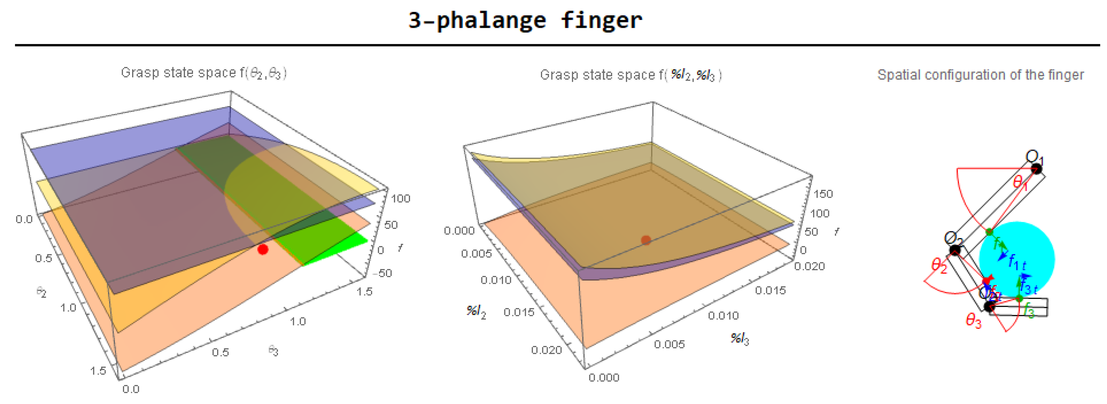
    the contact forces f 1 , f 2 , and f 3 are denoted respectively as yellow, orange, and blue surfaces in the grasp-state space graphs, while the green surfaces indicate the portion of the grasp-state spaces where the forces are all positive, therefore indicating a stable grasp. The green (stable grasp) or red (unstable grasp) point indicates the current configuration of the parameters ( θ 2 , k 2 ) for the two-phalanx finger or ( θ 2 , θ 3 ) and ( k 2 , k 3 ) for the three-phalanx finger;
    -
    the vectors representing the contact forces in the finger schemes are green or red if the forces are, respectively, positive or negative. The blue vectors, instead, indicate the tangential forces acting at the object contact points.
    Furthermore, the GUI language can be set (the current version only supports English and Italian).
  • Section 12—Results
    This section shows the main analytic outcomes obtained from the software: normal and tangential forces and values of the performance indexes both for two- and three-phalanx fingers. In the configuration considered in Figure 7, the grasped object, a disk, is positioned at the same distance from the base joint O 1 for the two finger architectures, but the grasp results stable only for the three-phalanx finger. This is due to the fact that, for the given combination of the chosen parameters, in the case of the two-phalanx finger the force f 2 is negative, while in the case of the three-phalanx finger all the forces are positive. Specifically:
    -
    as can be seen in the grasp-state space graph of the two-phalanx finger (Figure 8a), the force f 2 —orange surface—is always negative for each value of the ( θ 2 , k 2 ) parameters, so that the only way to obtain a stable grasp is that of changing the other parameters, such as the phalanx length or thickness, the friction coefficients, or the springs features;
    -
    in the case of the three-phalanx finger (Figure 8b) the first grasp-state space, which is a function of the ( θ 2 , θ 3 ) parameters, shows a stable grasp—green surface—just in the 38.2 % of the defined space, mainly due to the trend of f 2 surface; on the other hand, the second grasp-state space, which is a function of the ( k 2 , k 3 ) parameters, shows a stable grasp in the 91.2 % of the defined space.
    As an example, if in the case of the three-phalanx finger the friction coefficients are modified from μ 1 = μ 2 = μ 3 = 0.8 to μ 1 = μ 2 = μ 3 = 0.6 the grasp becomes unstable (as shown in Figure 9); this result highlights the importance of friction in the grasp stability problem and it also shows how this software could be useful in finding the best design parameters for an efficient underactuated gripper.
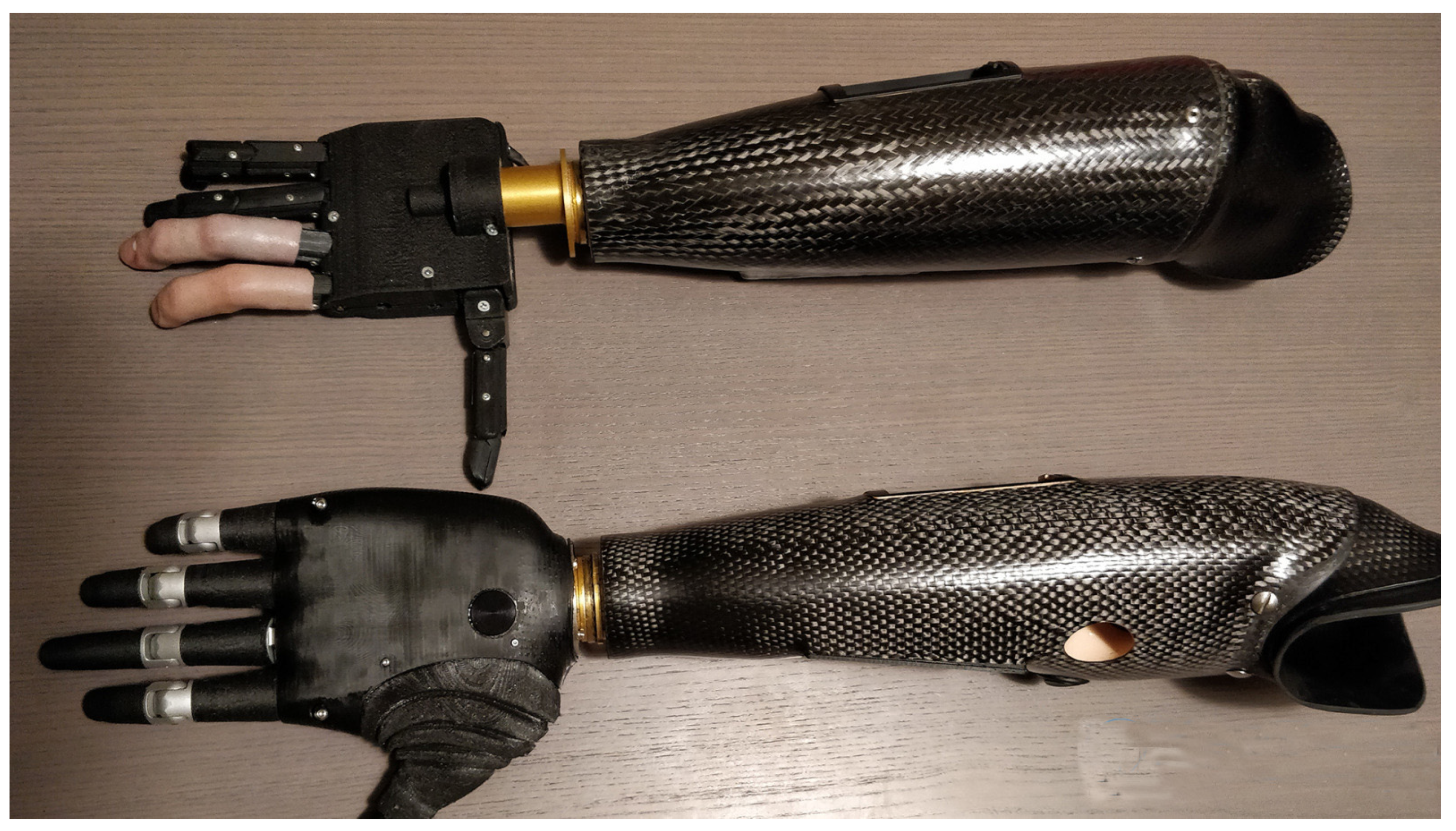
The proposed toolbox helped in the design choices of the Adam’s Hand prototype family that is shown in Figure 10. It was especially useful in setting the stiffness of the joint springs to increase the stable portion of the grasp-state space of Adam’s Hand.

5. Conclusions

In this paper, a software framework was presented to help a user during the design stage of a humanoid robotic hand that employs underactuated fingers towards grasp stability optimization. The tool is highly parameterized to cope with various parameters that include phalanx thickness and length, friction, joint spring properties, and driving torque. Although it was primarily intended for a parametric design of a humanoid underactuated hand using simulated grasping, it could also be valuable as an educational tool to help non-expert users or students to understand the principles underlying underactuated grasp by visualizing how the parameter slide bars impact on the stability indexes.
Future developments will be devoted to extend the single point contact model by also taking into account the linear and circular contact. The interaction with the grasped object by more than one finger at a time will be added to the system. Efforts will be made to include deformability of the phalanges, fingers, and grasped object towards a fully soft underactuated design. Finally, while many quality measures for grasps have been proposed in the literature, the use of these measures for automatic grasp choice remains an open issue [17]. Therefore, grasp quality metrics other than stability will be considered, for example, by taking into account the task requirement and following knowledge-based approaches.

Author Contributions

Conceptualization, G.A.Z., G.R. and A.M.; Investigation G.A.Z., G.R. and A.M.; Methodology, G.A.Z., G.R. and A.M.; G.A.Z., G.R. and A.M. wrote the paper.

Funding

The research leading to these results has received funding from the Horizon 2020 European Commission under grant agreement n. 821988 ADE.

Conflicts of Interest

The authors declare no conflict of interest.

References

  1. Russo, M.; Ceccarelli, M.; Corves, B.; Hüsing, M.; Lorenz, M.; Cafolla, D.; Carbone, G. Design and Test of a Gripper Prototype for Horticulture Products. Robot. Comput. Integr. Manuf. 2017, 44, 266–275. [Google Scholar] [CrossRef]
  2. Yao, S.; Ceccarelli, M.; Carbone, G.; Dong, Z. Grasp configuration planning for a low-cost and easy-operation underactuated three-fingered robot hand. Mech. Mach. Theory 2018, 129, 51–69. [Google Scholar] [CrossRef]
  3. Kragten, G.A.; Herder, J.L. The ability of underactuated hands to grasp and hold objects. Mech. Mach. Theory 2010, 43, 408–425. [Google Scholar] [CrossRef]
  4. Miller, A.; Allen, P. GraspIt! IEEE Robot. Autom. Mag. 2004, 11, 110–122. [Google Scholar] [CrossRef]
  5. Leon, B.; Ulbrich, S.; Diankov, R.; Puche, G.; Przybylski, M.; Morales, A.; Asfour, T.; Moisio, S.; Bohg, J.; Kuffner, J.; et al. Opengrasp: A toolkit for robot grasping simulation. Simul. Model. Program. Auton. Robot. 2010, 11, 109–120. [Google Scholar]
  6. Aukes, D.; Cutkosky, M. Simulation-based tools for evaluating underactuated hand designs. In Proceedings of the 2013 IEEE International Conference on Robotics and Automation (ICRA 2013), Karlsruhe, Germany, 6–10 May 2013; pp. 2067–2073. [Google Scholar] [CrossRef]
  7. Malvezzi, M.; Gioioso, G.; Salvietti, G.; Prattichizzo, D. SynGrasp: A MATLAB Toolbox for Underactuated and Compliant Hands. Robot. Autom. Mag. IEEE 2015, 22, 52–68. [Google Scholar] [CrossRef]
  8. Calli, B.; Walsman, A.; Singh, A.; Srinivasa, S.; Abbeel, P.; Dollar, A.M. Benchmarking in Manipulation Research: The YCB Object and Model Set and Benchmarking Protocols. IEEE Robot. Autom. Mag. 2015, 22, 36–52. [Google Scholar] [CrossRef]
  9. Adam’s Hand. Adam’s Hand Website. Available online: http://www.adamshand.it (accessed on 27 December 2018).
  10. Zappatore, G.A.; Reina, G.; Messina, A. Adam’s Hand: An Underactuated Robotic End-Effector. In Advances in Italian Mechanism Science; Springer: Cham, Switzerland, 2016; pp. 239–246. [Google Scholar]
  11. Zappatore, G.A.; Reina, G.; Messina, A. Analysis of a highly underactuated robotic hand. Int. J. Mech. Control 2017, 18, 17–24. [Google Scholar]
  12. Zappatore, G.A.; Reina, G.; Messina, A. A proposed software framework for studying the grasp stability of underactuated fingers. In Mechanism Design for Robotics, Proceedings of the IFToMM Symposium on Mechanism Design for Robotics, Udine, Italy, 11–13 September 2018; Springer: Cham, Switzerland, 2018; pp. 202–210. [Google Scholar]
  13. Birglen, L.; Laliberté, T.; Gosselin, C. Underactuated Robotic Hands; Springer: Berlin/Heidelberg, Germany, 2008. [Google Scholar]
  14. Wolfram, S. Mathematica: A System for Doing Mathematics by Computer; Wolfram Research Inc.: New York, NY, USA, 1988. [Google Scholar]
  15. Buryanov, A.; Kotiuk, V. Proportions of Hand Segments. Int. J. Morphol. 2010, 28, 755–758. [Google Scholar] [CrossRef]
  16. Oberg, E.; Jones, F.D.; Horton, H.L.; Ryffell, H.H.; Heald, R.M.; McCauley, C.J. Machinery’s Handbook; Industrial Press: South Norwalk, CT, USA, 2000. [Google Scholar]
  17. Okamura, A.; Smaby, N.; Cutkosky, M.R. An overview of dexterous manipulation. In Proceedings of the IEEE International Conference on Robotics and Automation, San Francisco, CA, USA, 24–28 April 2000; pp. 255–263. [Google Scholar]
Figure 1. The Adam’s Hand mechanism employs the following underactuation tree [11].
Robotics 08 00026 g001
Figure 2. Model of an underactuated finger.
Robotics 08 00026 g002
Figure 3. Impact of the phalanx thickness.
Robotics 08 00026 g003
Figure 4. Model of the underactuated 2-phalanx thumb (a) and determination of J I elements: vectors r 11 (b), r 12 (c), and r 22 (d).
Robotics 08 00026 g004
Figure 5. Model of the underactuated 2-phalanx thumb considering non-negligible phalanx thickness ϵ 1 , ϵ 2 (a) and determination of the components of vectors r 11 (b), r 12 (c), and r 22 (d).
Robotics 08 00026 g005
Figure 6. Model of the underactuated 3-phalanx finger studied, respectively considering negligible (a) and non-negligible (b) phalanx thickness.
Robotics 08 00026 g006aRobotics 08 00026 g006b
Figure 7. Graphical user interface (GUI) of the developed software. Please refer to the online colored version for a better view.
Robotics 08 00026 g007
Figure 8. Grasp-state space graphs and finger schemes of the two-phalanx finger (a) and of the three-phalanx finger (b).
Robotics 08 00026 g008
Figure 9. Grasp-state space graphs and configuration of the three-phalanx finger for an unstable grasp due to insufficient friction.
Robotics 08 00026 g009
Figure 10. Adam’s Hand prototype family: alpha-prototype at the top and beta-prototype at the bottom of the image.
Robotics 08 00026 g010
Table 1. Standard phalanx lengths [mm].
PhalanxThumb (I)Index ( II )Middle ( III )Ring ( IV )Pinkie (V)
d p 21.67 ± 1.60 15.82 ± 2.26 17.40 ± 1.85 17.30 ± 2.22 15.96 ± 2.45
m p - 22.38 ± 2.51 26.33 ± 3.00 25.65 ± 3.29 18.11 ± 2.54
p p 31.57 ± 3.13 39.78 ± 4.94 44.63 ± 3.81 41.37 ± 3.87 32.74 ± 2.77