Abstract
Autonomy of underwater vehicles has become an imperative feature due to increasingly challenging deep sea mission scenarios. In particular, for trajectory-tracking problems of Autonomous Underwater Vehicles (AUVs), the use of Lyapunov theory tools in state-of-the-art methods is common practice. These often require special assumptions, according to the application considered, and ‘intuition’ for the choice of a control law, which often leads to conservative results. This article suggests a systematic analysis for the horizontal motion of an AUV which ensures global asymptotic stability for the closed loop system. A nonlinear underactuated AUV system is considered with linear and angular velocity constraints. The Takagi–Sugeno (TS) framework design is adopted for the representation of the original nonlinear system. The control law is synthesised using the standard parallel distributed compensation (PDC) control law structure and stability is guaranteed for the closed loop system. The design criteria are posed as linear matrix inequalities (LMIs) where sufficient conditions for the design of the control law are shown. The proposed approach can be easily adopted for different types of autonomous vehicles with minor modifications.
1. Introduction
Autonomous Underwater Vehicles (AUVs) are vital to the exploration and exploitation of resources located at deep oceanic environments [1,2]. Besides their numerous practical applications (i.e., environmental surveying, military applications, undersea cable inspection, offshore oil installations, recovery of lost human-made objects, etc.), these vehicles present a challenging control problem since in many applications these are underactuated. Particularly, for AUVs, or in general marine vessels, there are no actuators in the sway and heave directions. In addition, AUVs’ kinematic and dynamic models are highly nonlinear and coupled [3,4], making the control design not a trivial task. Due to underactuation, a full state-feedback linearisation [5] control design may not be applicable. Moreover, the underactuated AUV system cannot be transformed into a standard chain system as in articles [6,7], and thus, existing control schemes (i.e., [3,8]) cannot be used. Furthermore, due to the complexity of hydrodynamics, an approach based only on the kinematic model may not be realistic [9].
Under the assumption that the AUV is moving on a horizontal plane, it presents a dynamic behaviour, which is similar to underactuated surface vessels, i.e., [10]. Additionally, it is stressed that the dynamics and control actuation models of AUVs are very similar to robotic airships, according to [3], and thus, similar tools may be used for the design of control law for the tracking problem. Among many articles in [11], the stabilisation problem, for surface vessels and AUVs has been studied. In particular, it is demonstrated that such vehicles cannot be asymptotically stabilised by continuous time-invariant feedback control laws. Lately, a variety of nonlinear design techniques have been developed for the tracking problem of an AUV. These can be categorised into two different groups, based on the tools used for the stabilisation of the closed loop system. The first category includes approaches that are based on the Lyapunov direct method, for example articles [10,12], while in the second category, the synthesis of the control law is based on linear time-varying control system theory, e.g., [13]. For example, article [14] reviewed different control techniques for the underpinned application and pointed to challenges.
In [15], a nonsingular fast terminal sliding mode controller is developed using tools from Lyapunov theory and is compared against the traditional nonsingular terminal sliding mode method. In [16], AUV tracking was achieved via backstepping methods. Articles [17,18] suggested the synthesis of the control law via sliding mode control methods. The use of the fast terminal sliding mode method was investigated in articles [19,20]. In particular, in the latter, ocean currents were utilised for the generated control input that minimise the energy demand for the thruster. In [21], the design of the state feedback controller for the solution of the position tracking problem was achieved provided that the reference surge velocity is of positive value and the heading of the marine vehicle was not controlled. A robust fractional-order proportional-integral-derivative controller is considered in [22] for yaw control of the AUV system. In [23], the authors developed a high gain dynamic feedback control law to achieve global ultimate regulation and tracking of underactuated ships. In particular, this was achieved via a special transformation for the controller that increased the complexity for the closed loop system. Using the backstepping technique, the design of a tracking controller for an AUV application subject to ocean currents was suggested in [24]. Specifically, the tracking problem was reduced to two separate problems; still, the methodology requires special assumptions that can often lead to conservative results. In [25], the Lyapunov-based model predictive controller with a fast finite time extended state observer is applied for the problem of formation keeping of AUVs. In [26,27], the combined problem of trajectory planning and tracking control for underactuated AUVs moving on the horizontal plane was investigated. In particular, the tracking error dynamics were stabilised using backstepping techniques. In another innovative solution in [28], the synthesis of the control law for the AUV application was performed via a time-varying velocity feedback controller. Using a special transformation of the original model and a choice of a new frame the AUV kinematic equations were simplified, and brought similarities with those of a wheeled robot. Among others, in [29], various control architectures for AUVs are discussed. Still, the focus was on low-level control systems rather than control architectures.
The limitations or hurdles on linear time-varying control system theory approaches are that those often exclude straight-line reference trajectories, and/or the stabilisation of the closed loop system becomes a hard task. Using Lyapunov’s direct method for synthesising the control law for the tracking problem of underactuated marine robotic vehicles is not a trivial task and requires some rigorous mathematical analysis for proving stability for the closed loop system. A common restriction on path tracking approaches is that the reference trajectory is persistently required to be curved, which limits their applicability in real-world systems. For example, in articles [10,12,13,30], among various assumptions for the synthesis of the control law, it is required for the reference yaw velocity to be persistently exciting (i.e., nonzero). The latter implies that straight-line trajectories cannot be tracked. In [12], via a change in coordinates and using the backstepping technique, the requirement for the synthesised control law is for the reference yaw angular velocity to be nonzero. Additionally, in [13,30], via a cascaded approach, the tracking error dynamics are proven k-exponentially stable. Compared to [12], although the resulting controller is much simpler in structure, the same assumption is required. Additionally, global tracking can be achieved via the method suggested by the authors in [10], provided that inertia and damping matrices are purely diagonal (i.e., assumption of before/after-symmetry), and the reference yaw angular velocity is persistent. The latter was overcome in [4,31,32], where straight-line trajectories are also feasible. The synthesis of the closed-loop system is performed using Lyapunov’s direct method and backstepping; still, the proposed controller cannot solve the stabilisation problem according to the condition imposed by [33] for any smooth, time-invariant state feedback law for underactuated systems. Thus, the same assumption is required for global exponential tracking. Similar limitations are evident in [34,35,36,37]. The assumption of persistent excitation is completely relaxed in work [38], where tracking can be achieved for both curved and rectilinear motion reference tracks. In particular, a state-feedback-based backstepping control algorithm is used where global exponential stability is proved via a mathematically rigorous three step procedure using Lyapunov theory tools and Barbalat’s Lemma. Still, most of the state-of-the-art methodologies using Lyapunov’s Direct method, which often require special assumptions, are system specific, and ‘intuition’ with respect to the choice of a control law may be imperative. Thus, a systematic approach for the problem of AUV tracking that can be applied to a large class of nonlinear systems still lacks from the literature.
In this article, we consider an underactuated vessel moving on the horizontal plane with two propellers: one is the surge force and the other the yaw moment. The aforementioned approach is common in real vehicles. The Takagi–Sugeno (TS) fuzzy model [39] is employed to tackle the problem, since it offers an alternative but efficient design approach. Its strength is that it can represent, with reduced mathematical complexity, a large class of nonlinear systems. Due to its structure, which is a fuzzy blending of linear local models, a systematic analysis for proving stability of the closed loop system is feasible.
To the best of our knowledge, within the TS framework and for the application considered in this article, there is a limited number of works. In particular, these only address the point-to-point stabilisation problem for the AUV in the horizontal frame [40], or the stabilisation problem for depth control [41]. Thus, the novel solution proposed in this article for the tracking problem of a reference trajectory (a priori prescribed) using the TS structure is expanding on previous work and is attractive to the interested reader. The control law for the proposed methodology is designed via Lyapunov theory tools and uses the standard PDC structure [42]. The feedback gains are synthesised, subject to certain design criteria, which are posed as Liner Matrix Inequalities (LMI) [39].
In particular, the approach suggested in article [43] is adopted, further enhanced, and modified to be applied to a different tracking problem. The latter is offering a systematic analysis and design to be used for the closed loop system, contrary to traditional methods that require special assumptions, are system specific, and require ’intuition’ with respect to the choice of a control law. This methodology can be implemented for any type of reference state vector and any initial conditions of the system, provided that the reference trajectory is feasible for the AUV, the premise variables are bounded, and the bounds on the state are a priori known. In this article, the reference track is generated using a two-step procedure. Firstly, the Dubins path is used, which is generated using the principles of Euclidean geometry [44]. Thereafter, following on the work by authors in [26], using the dynamics/kinematics for the AUV, the desired states to be tracked are generated for the Dubins track. In general, the generated TS is guaranteed to represent exactly the nonlinear model considered within the prescribed bounds on the state. For the underpinned application the premise variables are dependent on both the tracking error and the reference path. The former bounds can be selected by trial-and-error during the design process, and are chosen in order not to lose controllability (i.e., a priori defined allowable magnitude of the tracking error). By the latter, these are available from the reference track already available by the mission planification phase. Thus, these bounds are available. From a practical point of view, even in the case that the entire state is not available, it is common practice to use an observer-based design. For this case, the premise variables (i.e., bounds of the premise variables) are dependent on the measured state [45] and/or estimated state [46]. By the former, the synthesis of the observer and the control law can be performed independently, since the separation principle holds. Thus, the stability of the overall system is not compromised. By the latter, the design process is far from a trivial task. In essence, a triple sum of the weighting terms appears in the closed loop TS observer which does not allow finding tractable results. Examples can be found in articles [47,48] and book [49]. To overcome the latter, the design procedure may involve firstly the calculation of the state-feedback controller gains and then the fusion of the results obtained for the synthesis of the observer. Stability for the entire closed loop system can be performed a posteriori. Still, this is beyond the analysis herein and is left for future work.
The novelty of this work lies in the proposed methodology for analysing the tracking problem for AUVs. The creation of an equivalent TS representation form, as an intermittent step, allows a decoupled structure of the dynamics to be exploited. This structure enables a systematic analysis for stabilisation and tracking using Lyapunov theory. The resulting common Lyapunov matrix guarantees that the closed loop system is stable. The proposed approach is applicable to a variety of nonlinear systems.
The remainder of the article is structured as follows: in Section 2.2, the description of the AUV model is included. The generated reference track is described in Section 2.3. The tracking problem and the equivalent TS representation to the nonlinear AUV model are included in Section 2.4 and Section 2.5, respectively. In Section Optimal Tracking, the control law description and the stabilisation procedure for the closed loop system are described in detail. Finally, in Section 4, an AUV tracking scenario is included to illustrate the efficacy of the proposed approach, and concluding remarks are addressed in Section 5.
2. Preliminaries
2.1. Notation
The following notation is used hereafter. Inequality denotes that the matrix is symmetric negative definite. The transpose and inverse of any square matrix are denoted by and , respectively. The notation corresponds to a block diagonal matrix with for its diagonal elements. and correspond to the spectral norm of a matrix and the length of a vector, respectively. Asterisk in matrix expressions indicates a transposed quantity in the symmetric position. For example, is equivalent to . Finally, for .
2.2. AUV Model
According to [3], the equations of motion for an AUV moving on the horizontal plane can be derived using the global and body-fixed coordinate frames, respectively, as described in [27]. The origin of the body frame coincides with the AUV centre of mass. It is assumed that the inertia, added mass, and damping matrices are diagonal [11]. The equations governing the motion of the underactuated AUV satisfy Equation (1).
where is the position of the vehicle in coordinates, is the heading angle, , , and are the velocity in surge, sway and yaw, respectively, and denote the control inputs, which are the surge force and yaw torque, respectively, and the positive constants , for denote the AUV inertia including added mass, and the hydrodynamic parameters, respectively. These are appropriately selected according to the platform considered [3]. For simplicity, it is assumed that higher nonlinear damping terms are ignored, and the AUV is neutrally buoyant where the centre of buoyancy coincides with the centre of gravity of the vehicle.
2.3. Generation of the Reference Track—The Dubins Path
For the system in Equation (1), a feasible reference trajectory can be generated using model (1) and is denoted by the state vector , for the desired control vector . In this work, the reference track connecting two waypoints is generated using a two-step procedure. By the former step, the Dubins path is designed based on principles of Euclidean geometry, whilst satisfying physical/functional limitations of the vehicle. In [44], a detailed analysis and benefits of utilising such a trajectory is included. Thus, , and are available, which form a single/composite path consisting of circular and rectilinear segments. In general, given the initial and terminal constraints, there exist four paths for a given pair of waypoints. For our cause, the shortest Euclidean distance path is chosen.
In Equation (2), , are the initial and terminal constraints, and corresponds to constraints according to physical/functional limitations of the vehicle (i.e., minimum turning radius, etc.). Thereafter, by the latter step, via the Dubins path (i.e., for each circular/rectilinear segment), the reference states to be tracked are generated using the kinematics and dynamics of the AUV. This is performed following a backward procedure which was suggested in [27]. The requirement is for the path to be smooth, continuous, and three-times differentiable. The latter procedure is adopted in this work to generate a feasible reference track and the details follow herein.
Considering the differential equations in Equation (1) and assuming a given path to be tracked, then the AUV’s centre of mass linear velocity and heading angle are calculated via Equation (3), where the offset angle occurs based on the dynamics of the motion.
In particular, the AUV is required to point towards the inside of a curved path for the centre of mass to follow the path (assuming positive surge velocity). Solving Equation (3) for , differentiating the result, and substituting the derivative of the desired sway velocity from Equation (1), the desired surge velocity is presented in Equation (4).
Considering the vehicle when tracking a constant linear velocity and curved reference trajectory (i.e., ), it can be shown that , and . Thus, the steady-state values for surge, sway, and yaw velocities are generated as in Equation (5).
Substituting Equation (5) in Equation (1), the required thrusts for the steady-state velocities are equal to,
This approach yields good tracking for composite paths consisting of rectilinear and circular segments with constant linear and angular velocities.
Remark 1.
For a more generic path (i.e., the path’s curvature and/or linear velocity are not constant), then the full steady-state approach can be modified using Equation (1). This will include the actual values for , while keeping the same values for , , and assuming that is negligible. The latter implies that , , while as before. Thus, Equation (6) becomes
Following the previous procedure, an example reference trajectory and the required thrusts for the AUV are depicted in Figure 1, and Figure 2 for a given set of initial/terminal constraints (i.e., and ), and the minimum turning radius set to 70 [m].
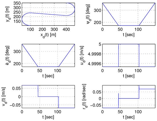
Figure 1.
Generated state vector for an example Dubins reference trajectory given initial/terminal constraints with minimum turning radius equal to 70 [m].
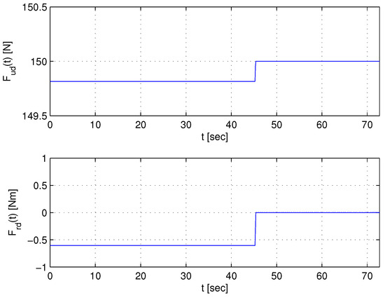
Figure 2.
Required thrust vector for the example composite path calculated as in Equation (6).
Remark 2.
The proposed approach is limited to a reference track of the particular properties. In general, due to the discontinuities in the Dubins path, the resulting path may not be smooth. In essence, the discontinuities are appearing in the points where the pattern changes from a linear to circular segment, and otherwise. Hence, a change in direction induces lateral acceleration acting along the tangent by perpendicular means, which cannot be handled directly by the Dubins path unless the AUV reduced its speed whilst approaching the point where the discontinuity occurs. The latter was illustrated in [44]. Thus, smoothness of the path is required, which will be the topic of future work. Furthermore, special operators need to be tailored for producing reference tracks that fulfil the latter assumptions. For example, in the literature, Genetic Algorithms can be employed with a sacrifice of computational complexity and accuracy to shape/smooth the reference track via composite parametric curves and fulfil the mission’s objectives whilst satisfying functional and physical limitations of the vehicle. For example, see articles [50,51,52] and references therein for a thorough treatment. In particular, via the use of a ‘polyBezier’, one can enforce various constraints, such as positional , velocity , tangent continuity , etc.
In general, there exists a large number of methods for the path planning problem whilst bathymetry data are fully available or partially known [53]. For example, among many, in [54], an off-line or on-line procedure (depending on prior knowledge of the terrain of the sea bed) is suggested. The features of the path planner are based on evolutionary algorithms. Still, special operations need to be considered provided that constant linear velocity for the vehicle during the mission is required. Such a procedure can be used herein to provide a waypoint-based path for the AUV to track in order to complete its mission’s objectives and is considered as future work. With the previous in place, the tracking problem involves the design of a control law such that the vehicle model in Equation (1) follows the reference track.
2.4. AUV Tracking Problem
The error model of the AUV is generated with the aid of the reference and the current state vector whilst utilising the kinematics in Equation (1). According to [3], the tracking error for the AUV is governed by:
Taking the time derivative of the tracking error in (8), substituting for the model (1) and the reference profile (generated using the procedure described in Section 2.3), yields
Applying the feed-forward control action vector in Equation (10) to Equation (9), and putting it in matrix form this results in the error dynamics (11).
where and equal to the matrices in (12) and (13), respectively,
, the tracking error vector, and the feedback control action vector. The task is to design control inputs such that for the closed loop system in Equation (11) as . The intuition of applying the virtual control law in Equation (10) is not only to simplify the closed loop system for the design process, but also to achieve smoother response via the feed-forward reference control input compared to just using feedback terms. The dynamics in Equation (11) can be transformed into an equivalent Takagi–Sugeno (TS) representation [39]. As illustrated in reference [55], the benefit of such a transformation is that a systematic methodology can be used for the design of the controller for stabilisation/tracking purposes.
2.5. Equivalent TS Model for the Error Dynamics of the AUV
In this section, the TS fuzzy model and the derivation of the equivalent system (11) in TS form are included. The TS model is a set of first-order ODEs that are expressed as a convex sum of linear models via nonlinear functions (i.e., membership functions). These membership functions satisfy the convex sum property. Consider the error system in Equation (11), where , are the state and input vectors, respectively. The nonlinear model in Equation (11) can be represented in a compact region of the state-space by a TS fuzzy model utilising the sector nonlinearity approach [39].
Adopting the notation in reference [39], for the vehicle, the TS fuzzy model is formed by local linear subsystems, where the number of rules r is determined according to the length of the premise vector z chosen and is equal to . In particular, here is a known premise vector, which may depend on the state vector, with (i.e., ). The premise variables for the model illustrated in Equation (11) are chosen as , , , , and . The premise variables are required to be bounded and the bounds need to be a priori defined for the TS to exactly represent the nonlinear model considered [39].
Here, it is assumed that , for . For simplicity, in this work, , , and . It is noted that the bounds on , , are a priori known since the reference track is available according to Section 2.3. For the reference track example shown in the simulation Section 4, those are chosen as , , and . In general, the latter bounds are not chosen in an arbitrary manner, and are selected according to design specs of the AUV, and in order not to lose controllability. The TS is represented by implications of form or Input-Output form. Since , the number of rules of the fuzzy system is equal to . The general layout for the model rule is:
Model Rule [39] for the system:
IF is AND …AND is THEN
where the symbols , for denote the fuzzy sets and are normalised to unity. The fuzzy sets are generated utilising the sector nonlinearity approach [56]. To summarise the sector nonlinearity technique, consider nonlinear function bounded on , and let , and denote its minimum, and maximum values, respectively. Then, f is equal to , and is enforced. Thus, the membership functions are equal to and . In Equation (14), and are constant matrices (for the corresponding minimum and maximum values of the premise variables, respectively) and are equal to:
In Input-Output form, the defuzzification process of system in Equation (14) can be represented by the following polytopic form:
where and the are normalised weighting functions defined by:
and is the grade of the membership function of in fuzzy set . The weighting terms satisfy the convex sum property for all t (i.e., ). By construction, are of positive value since , and .
In this work, the weighting terms depend both on the reference state and the tracking error. Thus, provided that the bounds on the variables are a priori known, the TS model in Equation (16) is an exact representation of the nonlinear model (11) inside . It is noted that substituting Equation (17) in Equation (16), for the generated matrices in (15) and the given bounds on the state, yields Equation (11). In this article, the control vector in Equation (16) is designed using tools from Lyapunov theory.
3. Control Law Description and Optimal AUV Tracking
In contrast to pure Lyapunov-based methods for solving the AUV tracking problem, the proposed TS framework offers a systematic approach applicable to a variety of nonlinear systems. In the next section, the synthesis of the control law, for the path tracking problem, is discussed. The task is for the tracking error as . The stabilisation of the dynamics in Equation (16) is performed using tools from linear control theory. The design criteria are posed as linear matrix inequalities (LMIs) where sufficient conditions for the design of the control law are shown.
Optimal Tracking
In this work, the standard parallel distributed compensation (PDC) control law structure is used. In Equation (16), control law maintains the same structure as the model rules. Hence, the control rule corresponds to:
Control Rule :
IF is AND …AND is THEN
for . The overall state feedback control law is:
where are the feedback gains. Injecting the control law of Equation (18) into Equation (16), the closed loop system is equal to:
where . The dynamics in Equation (19) are expanded to (20) in order to have more relaxed conditions. The latter is suggested by authors in [39].
The synthesis of the control law (18) in (20) is achieved via Lyapunov theory tools. Hence, the task is to determine the feedback gains , and Lyapunov matrix (i.e., , and ), such that performance criteria posed as LMIs are satisfied in an optimal sense. This is performed whilst minimising the upper bound of the quadratic performance function:
where matrices and are symmetric and positive definite. Matrices , and are used to penalise the error on the state and control effort , respectively. Assuming positive definite Lyapunov function , if its derivative satisfies
then integrating (22) over , it can be shown that [39]. It follows that J is upper bounded wrt the initial conditions. Thus, is minimised instead of J. According to [39], the fuzzy system in (16) is stabilised via the PDC control law in (18), provided that following inequalities are satisfied.
where , and
and
The proof is summarised in Appendix A. The notation implies that the conditions hold for except if for all . The conditions are valid provided that two rules are active simultaneously. The solution of the Bilinear Matrix Inequality (BMI) problem in (23) is not a trivial task. The latter can be circumvented by its transformation into an LMI problem. This is performed by before/after multiplying with , and substituting with , with . Hence, the LMIs are equal to:
where , and
and
Thus, an upper bound on the performance index (21) can be determined (i.e., ), and the stabilisation of the error dynamics for the system in (16) is guaranteed via the PDC control law in (18) if there exists a symmetric positive definite matrix, () and matrices for such that the minimisation problem
is subject to the conditions from (24), and
is solved for . Thus, inequality (22) is satisfied, and stability is guaranteed for any . Provided there exists a solution for the LMI problem the feedback gains are calculated as:
It is noted that via and , then the standard stable controller is concerned. For this case, the control law is synthesised via the solution of the LMI problem with inequalities that correspond to only the first elements in the diagonal of conditions in (24) (i.e., LMIs , and , for , with ).
Remark 3.
Remark 4.
Remark 5.
Additionally, even for the case where the LMI problem is infeasible, slack variables can be introduced in the right hand side of the conditions, in order to find sufficient conditions to the problem, for example refer to [39,57].
Provided that the previous minimisation problem subject to the corresponding LMIs has a solution, then stability for the closed loop system is guaranteed. Convergence rates are affected by the choice of weighting matrices and and the decay rate . In fact, penalises the error on the state, while penalises the control effort. Additionally, the speed of response for the closed loop system is related to the inclusion of the decay rate used in LMIs previously, and is the largest Lyapunov exponent. The matrices and and the decay rate are chosen judiciously to tune the controller performance. For example, penalising the error on the state may yield faster response with a sacrifice of greater control effort. Thus, different responses of the system can be obtained according to design specifications at hand.
It is noted that herein, the choice of premise variables is not unique and another (i.e., greater in number) may yield a different TS fuzzy system equivalent to the original nonlinear system. For example, instead of choosing five premise variables, one may consider seven, keeping in mind separating the tracking error from reference track variables. This may lead to the number of LMIs to grow rapidly (i.e., according to the length of ), rendering the solution of the LMI problem intractable. Thus, the problem of the solution of LMIs may become a hard task. Additionally, provided this is feasible, the resulting more complex controller may not necessarily yield better performance compared to using less premise variables. Still, herein, the choice of the premise variables was performed with reduced mathematical complexity in mind, for the solution of the LMIs. Furthermore, common quadratic Lyapunov functions tend to be conservative and may not exist for complex or large-scale nonlinear systems. To overcome this, it is common practice to use piecewise quadratic Lyapunov functions (see for example articles [58,59]). In addition, for the case of large-scale systems, via a special structure for the common Lyapunov matrix, complexity can be reduced. The latter is evident in article [60]. Finally, modifying the analysis shown in the proposed developments, ocean currents, variation in the hydrodynamic parameters, noise in measurements, unanticipated faults in the control surface or sensors, delay in the system’s components, etc. can be added in the design in order to address real-world scenarios more closely. In particular, via the augmentations suggested in books [39,49], similar tools for disturbance rejection, robust control, and estimation of unknown parameters via observer-based approaches can be adopted for the stabilisation of the error dynamics underpinned in this article, and are future directions. The efficacy of the approach is highlighted via an example scenario, presented in detail in Section 4.
4. Simulation Results
To highlight the applicability of the proposed approach, a tracking scenario is considered for an AUV deployed to follow an a priori known prescribed trajectory from any initial conditions satisfying the bounds on the state space. The reference track considered for the AUV is generated according to the procedure described in Section 2.3. Specifically, five waypoints are considered with the corresponding heading angle constraint in each waypoint. Thus, four legs are required for the completion of the mission, where each pair of waypoints is connected via the generated Dubins path. For each leg, the shortest Euclidean distance path, from the four available Dubins tracks, is selected. Hence, for the resulting composite reference path (illustrated in blue colour in Figure 3), the reference thrust vector is generated according to Equation (6).
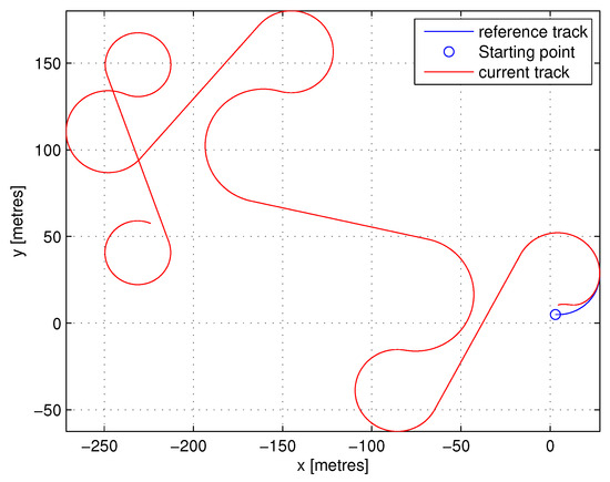
Figure 3.
Reference trajectory (in blue colour) versus control track (in red colour).
The required thrust vector profile is depicted in Figure 4 with the dashed blue line. Note that the proposed controller can be used with any type of trajectory provided that this is smooth, continuous, and three-times differentiable.
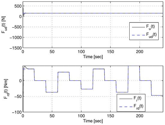
Figure 4.
Overall control action vector according to Equation (10).
We consider the underactuated AUV in Equation (1) moving on the horizontal plane. The TS fuzzy model has been derived as described in Section 2.5. For the model illustrated in Equation (11), the premise variables are chosen as , , , , and .
The premise variables are required to be bounded and the bounds need to be a priori defined in order for the TS to exactly represent the nonlinear model considered [39]. Here, it is assumed that , for . In this work, , , and , and are chosen in order not to lose controllability of the system.
The number of fuzzy rules is equal to and the length of the premise vector is equal to . Utilising the sector nonlinearity approach in [56], the membership functions are determined and the weighting terms are calculated according to Equation (17). All rules are developed as prescribed in Section 2.5 Equation (14), where and are shown in (15) for the corresponding limits on the premise variables. Finally, the defuzzification is carried out with respect to Equation (16). The equivalent TS fuzzy model (16) to the nonlinear system in Equation (11) is derived. To summarise the procedure for the generation of the equivalent TS representation to the nonlinear system, four steps are followed:
- Choice of the premise vector and calculation of bounds based on the compact region on the state ;
- Definition of the membership functions;
- Determination of all possible model rules r composed of the premise variables and the ranking of the membership function of the premise variable;
- Calculation of the matrices and , for with respect to the bounds on the premise variables;
In this example, the control law considered is of the form of Equation (18). The task is for the AUV to track a prescribed reference trajectory. In particular, for the tracking error as . According to Section 3, the LMIs are synthesised for the closed loop error system in Equation (19). The choice of the feedback gains and a common positive definite matrix is made by minimising (25) subject to the LMI conditions in (26), and (24). For the solution of the minimisation problem, the YALMIP toolbox [61] is used. In particular, the optimisation problem is feasible, and the resulting eigenvalue distribution for and the positive definite matrix is illustrated in Figure 5.
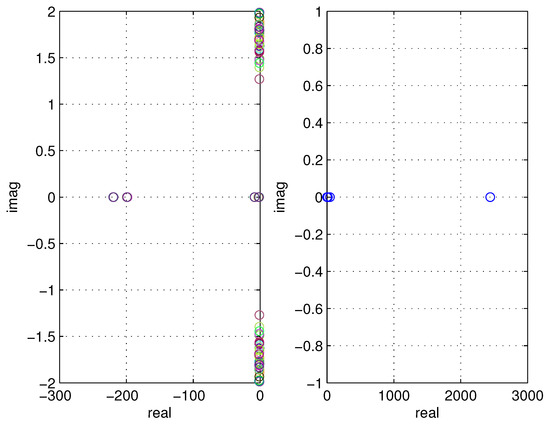
Figure 5.
Eigenvalue distribution (left) and (right) for the synthesised controller. The colour in the left figure corresponds to the corresponding subsystem of the TS.
The positive definite matrix returned is equal to:
For the minimisation problem of (25), subject to LMIs (26) and (24), and . In (24), and . To derive different responses of the system, we alter the elements in and matrices. Therefore, we can obtain different control performance according to design specifications at hand.
As depicted in Figure 6, the bounds on the state space are not violated, and thus, the TS model represents exactly the nonlinear model of the error dynamics of the AUV.
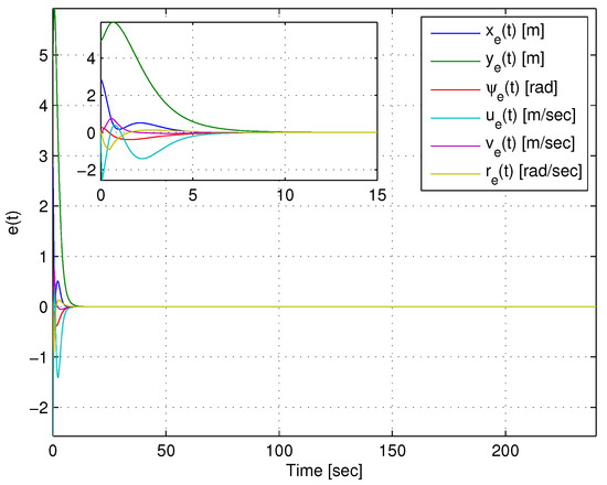
Figure 6.
Tracking error according to Equation (8).
The overall control law in Equation (18) is synthesised and is added to the feed-forward control action vector in Equation (10). The overall control input consists of the surge force and the yaw torque which are fed to the AUV model in Equation (1). To calculate the tracking error (Equation (8)), we use the measured state of the vehicle. The initial conditions for the AUV are chosen whilst satisfying the a priori assumed bounds on the state space. The AUV trajectory in relation with the reference track is depicted in Figure 3. The tracking error () is given in Figure 6.
The premise vector and the firing of the weighting functions are shown in Figure 7 and Figure 8, respectively.
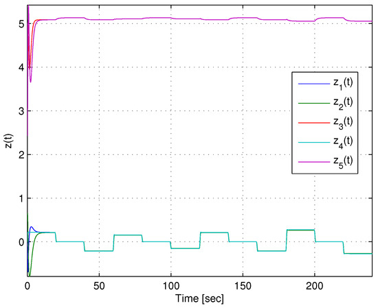
Figure 7.
Premise variables for the TS.
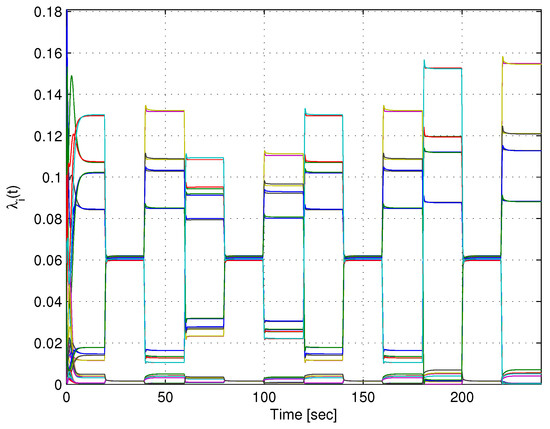
Figure 8.
Weighting terms .
The overall control law (10) is illustrated in Figure 4. The Lyapunov candidate function is shown in Figure 9.
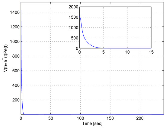
Figure 9.
Lyapunov candidate function .
The membership functions that are generated via the sector nonlinearity approach for the derived TS model are included in Figure 10. It is stressed that the membership functions are determined using the bounds enforced on the premise part along the entire reference trajectory. These bounds are available by both the reference trajectory and the error on the state, which are a priori known. The membership functions are used for the calculation of the weighing terms in the TS and are dependent on the premise variables already assumed. Thus, provided a different reference trajectory is used, these are updated accordingly. Additionally, in the scenario example considered, the composite reference track consists of several Dubins paths (i.e., connected back-to-back) with various minimum turning radiuses for each leg (i.e., four in total). Since the synthesis of the controller greatly depends on the reference track considered then the feedback gains need to be updated and tuning for the parameters in the LMIs is required. Still, provided a random reference track is given that does not violate the bounds on the premise parts already in place, then the controller will perform satisfactorily. The latter is due to the TS that exactly represents the initial nonlinear system within these bounds. In contrary, if these are violated, then stability for the closed loop system is also jeopardised, and a redesign process is imperative.
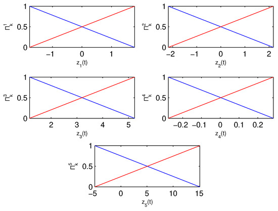
Figure 10.
Membership functions for , , , , and , respectively.
The advantage of using the proposed developments owes to its systematic approach to be used for the synthesis of the control law for the problem of AUV tracking via the TS framework and well-established tools from linear control theory, compared to pure Lyapunov-based methods (i.e., [4,10,36], for example). In particular, these methods require special assumptions, are system specific, and require ’intuition’ with respect to the choice of a control law. Thus, although comparing against state-of-the-art methods may produce similar results with respect to tracking performance, the synthesis of the proposed controller follows a systematic treatment. The latter is also evident in articles [39,48,62], for example. Additionally, variations in system parameters and/or relaxing on the assumption for purely diagonal inertia and damping matrices (i.e., assumption of before/after-symmetry) may affect the performance for the designed closed loop system. A future direction may be the extension of the proposed developments to include robustness capability for the closed loop system.
5. Conclusions
In this article, a novel and systematic analysis for the horizontal motion of an underactuated AUV which ensures global asymptotic stability for the closed loop system is considered. An underactuated AUV nonlinear system is considered with linear and angular velocity constraints in the TS form. The control law is synthesised using the PDC control law structure. This is performed using tools from linear control theory: in particular, the design criteria are posed as LMIs, and the synthesis of the control law is performed whilst minimising performance criteria. An example based on an AUV tracking scenario illustrated the efficacy of the approach.
In future work, we will consider devising strategies such that less conservative conditions are employed in order to reduce the computational complexity of the LMIs. Other interesting aspects are modifying the underpinned system to include disturbance terms (either known or unknown), uncertainty in parameters, and faults in actuators and sensors, and designing the control law not only to complete the mission’s objectives but also to estimate any unknown parameters.
Author Contributions
Conceptualization, G.P.K.; Methodology, G.P.K. and L.D.; Software, G.P.K.; Formal analysis, G.P.K., L.D. and N.C.T.; Investigation, G.P.K., L.D. and N.C.T.; Writing—original draft, G.P.K. and L.D.; Writing—review and editing, G.P.K., L.D. and N.C.T. All authors have contributed equally to the proposed developments in this article. All authors have read and agreed to the published version of the manuscript.
Funding
This research received no external funding.
Data Availability Statement
The data presented in this study are available on request from the corresponding author due to privacy.
Conflicts of Interest
The authors declare no conflicts of interest.
Abbreviations
The following abbreviations are used in this manuscript:
| AUV | Autonomous Underwater Vehicle |
| TS | Takagi–Sugeno |
| PDC | Parallel Distributed Compensation |
| LMI | Linear Matrix Inequality |
Appendix A
Theorem A1.
Proof.
Defining the new variable , then the performance index (21) is equal to:
where . From the Schur complements, it yields
and
where, , , and it follows that and . Thus, the fuzzy control system is globally asymptotically stable if (23) hold. Next, we will prove that . Consider Lyapunov function , using (A2), (A3), and corollaries A1 and A2, taking the derivative of and substituting the closed loop dynamics in (20), we have:
and therefore, and integrating both sides yields . Since the fuzzy control system is stable, this yields . Thus, instead of the minimisation of J, its upper bound (i.e., ) is minimised. It follows that by the transformation of (23) into LMIs, then the upper bound satisfies and J is minimised. Hence, an upper bound on (21) can be determined, and the stabilisation of the error dynamics for the system in (16) is guaranteed via the PDC control law in (18) if there exists a symmetric positive definite matrix, () and matrices for such that the minimisation problem (25) subject to the conditions from (26), and (24) is solved for . □
Corollary A1.
where .
Proof.
The proof follows easily. □
Corollary A2.
in , and .
Proof.
From (A5) we have
□
References
- Rogers, A.; Brierley, A.; Croot, P.; Cunha, M.; Danovaro, R.; Devey, C.; Hoel, A.; Ruhl, H.; Sarradin, P.M.; Trevisanut, S.; et al. Delving Deeper: Critical Challenges for 21st Century Deep-Sea Research; Larkin, K.E., Donaldson, K., McDonough, N., Eds.; Position Paper 22; European Marine Board: Ostend, Belgium, 2015. [Google Scholar]
- Sahoo, S.; Choudhury, B.; Dhal, P. Exploring the Role of Robotics in Maritime Technology: Innovations, Challenges, and Future Prospects. Spectr. Mech. Eng. Oper. Res. 2024, 1, 159–176. [Google Scholar] [CrossRef]
- Fossen, T.I. Guidance and Control of Ocean Vehicles; Wiley: New York, NY, USA, 1994. [Google Scholar]
- Do, K.D.; Pan, J. Control of Ships and Underwater Vehicles: Design for Underactuated and Nonlinear Marine Systems; Springer: London, UK, 2009. [Google Scholar]
- Khalil, H.K. Nonlinear Systems, 3rd ed.; Prentice Hall, Inc.: Saddle River, NJ, USA, 2002. [Google Scholar]
- Sordalen, O.; Egeland, O. Exponential stabilization of nonholonomic chained systems. IEEE Trans. Autom. Control 1995, 40, 35–49. [Google Scholar]
- Pettersen, K.; Egeland, O. Exponential stabilization of an underactuated autonomous surface vessel. In Proceedings of the 35th IEEE Conference on Decision and Control, Kobe, Japan, 11–13 December 1996; pp. 967–971. [Google Scholar]
- Murray, R. Control of nonholonomic systems using chained forms. Fields Inst. Commun. 1993, 1, 219–245. [Google Scholar]
- Nakamura, Y.; Savant, S. Nonlinear tracking control of autonomous underwater vehicles. In Proceedings of the 1992 IEEE International Conference on Robotics and Automation, Nice, France, 12–14 May 1992; Volume 3, pp. A4–A9. [Google Scholar]
- Jiang, Z.P. Global tracking control of underactuated ships by Lyapunov’s direct method. Automatica 2002, 38, 301–309. [Google Scholar] [CrossRef]
- Pettersen, K.Y.; Egeland, O. Time-Varying Exponential Stabilization of the Position and Attitude of an Underactuated Autonomous Underwater Vehicle. IEEE Trans. Autom. Control 1999, 44, 112–115. [Google Scholar] [CrossRef]
- Pettersen, K.; Nijmeijer, H. Global practical stabilization and tracking for an underactuated ship-a combined averaging and backstepping approach. In Proceedings of the IFAC Conference on Systems Structure Control, Tampa, FL, USA, 12–19 December 1998; pp. 59–64. [Google Scholar]
- Lefeber, E.; Pettersen, K.; Nijmeijer, H. Tracking Control of an Underactuated Ship. IEEE Trans. Control Syst. Technol. 2003, 11, 52–61. [Google Scholar]
- Li, D.; Du, L. AUV Trajectory Tracking Models and Control Strategies: A Review. J. Mar. Sci. Eng. 2021, 9, 1020. [Google Scholar] [CrossRef]
- Wang, Y.; Du, Z. Trajectory Tracking Control for an Underactuated AUV via Nonsingular Fast Terminal Sliding Mode Approach. J. Mar. Sci. Eng. 2024, 12, 1442. [Google Scholar] [CrossRef]
- Cho, G.; Li, J.; Park, D.; Jung, J. Robust trajectory tracking of autonomous underwater vehicles using back-stepping control and time delay estimation. Ocean Eng. 2020, 201, 107–131. [Google Scholar]
- Elmokadem, T.; Zribi, M.; Youcef-Toumi, K. Trajectory tracking sliding mode control of underactuated AUVs. Nonlinear Dyn. 2016, 86, 1079–1091. [Google Scholar]
- Ma, C.; Jia, J.; Zhang, T.; Wu, S.; Jiang, D. Horizontal trajectory tracking control for underactuated autonomous underwater vehicles based on contraction theory. J. Mar. Sci. Eng. 2023, 11, 805. [Google Scholar] [CrossRef]
- Yang, X.; Yan, J.; Hua, C.; Guan, X. Trajectory tracking control of autonomous underwater vehicle with unknown parameters and external disturbances. IEEE Trans. Syst. Man Cybern. Syst. 2021, 51, 1054–1063. [Google Scholar] [CrossRef]
- Heshmati-Alamdari, S.; Bechlioulis, C.; Karras, G.; Kyriakopoulos, K. Cooperative Impedance Control for Multiple Underwater Vehicle Manipulator Systems Under Lean Communication. IEEE J. Ocean. Eng. 2020, 46, 447–465. [Google Scholar] [CrossRef]
- Godhavn, J.; Fossen, T.; Berge, S. Nonlinear and adaptive backstepping designs for tracking control of ships. Int. J. Adapt. Control Signal Process. 1998, 12, 649–670. [Google Scholar] [CrossRef]
- Liu, L.; Zhang, L.; Pan, G.; Zhang, S. Robust yaw control of autonomous underwater vehicle based on fractional-order PID controller. Ocean Eng. 2022, 257, 111493. [Google Scholar] [CrossRef]
- Olfati-Saber, R. Nonlinear Control of Underactuated Mechanical Systems with Application to Robotics and Aerospace Vehicles. Ph.D. Thesis, Massachusetts Institute of Technology, Cambridge, MA, USA, 2001. [Google Scholar]
- Yang, X.; Li, J. Trajectory tracking control of underactuated AUV in the presence of ocean currents. Int. J. Control Autom. 2016, 9, 81–92. [Google Scholar] [CrossRef]
- Yan, Z.; Zhang, M.; Zhou, J.; Yue, L. Distributed Lyapunov-Based Model Predictive Control for AUV Formation Systems with Multiple Constraints. J. Mar. Sci. Eng. 2024, 12, 363. [Google Scholar] [CrossRef]
- Repoulias, F.; Papadopoulos, E. Trajectory planning and tracking control design of underactuated AUVs. In Proceedings of the IEEE International Conference on Robotics and Automation, ICRA 05, Barcelona, Spain, 18–22 April 2005; pp. 1622–1627. [Google Scholar]
- Repoulias, F.; Papadopoulos, E. Planar trajectory planning and tracking control design for underactuated AUVs. Ocean Eng. 2007, 34, 1650–1667. [Google Scholar] [CrossRef]
- Lapierre, L.; Soetanto, D. Nonlinear Path-following Control of an AUV. Ocean Eng. 2007, 34, 1734–1744. [Google Scholar] [CrossRef]
- Valavanis, K.; Gracanin, D.; Matijasevic, M.; Kolluru, R.; Demetriou, G. Control architectures for autonomous underwater vehicles. IEEE Control Syst. Mag. 1997, 17, 48–64. [Google Scholar]
- Lefeber, E. Tracking Control of Nonlinear Mechanical Systems. Ph.D. Thesis, University of Twente, Enschede, The Netherlands, 2000. [Google Scholar]
- Do, K.D.; Pan, J.; Jiang, Z.P. Global Exponential Tracking Control of Underactuated Surface Ships in the Body Frame. In Proceedings of the American Control Conference, Anchorage, AK, USA, 8–10 May 2000; pp. 4702–4707. [Google Scholar]
- Do, K.D.; Jiang, Z.P.; Pan, J. Underactuated Ship Global Tracking under Relaxed Conditions. IEEE Trans. Autom. Control 2000, 47, 1529–1536. [Google Scholar] [CrossRef]
- Brockett, R.W. Asymptotic stability and feedback stabilization. In Differential Geometric Control Theory; Millman, R.S., Brockett, R.W., Sussmann, H.J., Eds.; Birkauser: Basel, Switzerland, 1983. [Google Scholar]
- Soltan, R.; Ashrafiuon, H.; Muske, K. State-dependent trajectory planning and tracking control of unmanned surface vessels. In Proceedings of the American Control Conference, St. Louis, MO, USA, 10–12 June 2009; IEEE: Piscataway, NJ, USA, 2009; pp. 3597–3602. [Google Scholar]
- Ma, B.; Xie, W. Global asymptotic trajectory tracking and point stabilization of asymmetric underactuated ships with non-diagonal inertia/damping matrices. Int. J. Adv. Robot. Syst. 2013, 10, 336. [Google Scholar]
- Harmouche, M.; Laghrouche, S.; Chitour, Y. Global tracking for underactuated ships with bounded feedback controllers. Int. J. Control 2014, 87, 2035–2043. [Google Scholar] [CrossRef][Green Version]
- Liao, Y.; Su, Y.; Cao, J. Trajectory planning and tracking control for underactuated unmanned surface vessels. J. Cent. South Univ. 2014, 21, 540–549. [Google Scholar]
- Dong, Z.; Wan, L.; Li, Y.; Liu, T.; Zhang, G. Trajectory tracking control of underactuated USV based on modified backstepping approach. Int. J. Nav. Archit. Ocean Eng. 2015, 7, 817–832. [Google Scholar] [CrossRef]
- Tanaka, K.; Wang, H.O. Fuzzy Control Systems Design and Analysis: A Linear Matrix Inequality Approach; John Wiley and Sons, Inc.: New York, NY, USA, 2001. [Google Scholar]
- Chang, M.; Chang, W.; H Liu, H. Model-based fuzzy modeling and control for autonomous underwater vehicles in the horizontal plane. J. Mar. Sci. Technol. 2003, 11, 155–163. [Google Scholar] [CrossRef]
- Jun, S.; Kim, D.; Lee, H. Design of TS fuzzy model-based controller for depth control of autonomous underwater vehicles with parametric uncertainties. In Proceedings of the 11th International Conference of Control, Automation and Systems (ICCAS), Gyeonggi-do, Republic of Korea, 26–29 October 2011; pp. 1682–1684. [Google Scholar]
- Wang, H.O.; Tanaka, K.; Griffin, M.F. Parallel Distributed Compensation of Nonlinear Systems by Takagi-Sugeno Fuzzy Model. In Proceedings of the 1995 IEEE International Conference on Fuzzy Systems, Yokohama, Japan, 20–24 March 1995; pp. 531–538. [Google Scholar]
- Kladis, G.P.; Menon, P.P.; Edwards, C. Cooperative tracking for a swarm of Unmanned Aerial Vehicles: A distributed Tagaki-Sugeno fuzzy framework design. In Proceedings of the 50th IEEE Conference on Decision and Control and European Control Conference (CDC-ECC), Orlando, FL, USA, 12–15 December 2011; pp. 4114–4119. [Google Scholar]
- Shanmugavel, M. Path Planning of Multiple Autonomous Vehicles. Ph.D. Thesis, Cranfield University, Wharley End, UK, 2007. [Google Scholar]
- Tanaka, K.; Wang, H.O. Fuzzy Regulators and Fuzzy Observers: A Linear Matrix Inequality Approach. In Proceedings of the 36th IEEE Conference on Decision and Control, San Diego, CA, USA, 12 December 1997; Volume 2, pp. 1315–1320. [Google Scholar]
- Tanaka, K.; Ikeda, T.; Wang, H.O. Fuzzy Regulators and Fuzzy Observers. IEEE Trans. Fuzzy Syst. 1998, 6, 250–265. [Google Scholar] [CrossRef]
- Delmotte, F.; Lauber, J.; Guerra, T.M. A multi-model controller. In Proceedings of the 2008 IEEE International Conference on Fuzzy Systems (IEEE World Congress on Computational Intelligence), Hong Kong, China, 1–6 June 2008; pp. 1524–1529. [Google Scholar]
- Guerra, T.M.; Kruszewski, A.; Vermeiren, L.; Tirmant, H. Conditions of output stabilization for nonlinear models in the Takagi–Sugeno form. Fuzzy Sets Syst. 2006, 157, 1248–1259. [Google Scholar] [CrossRef]
- Bernal, M.; Sala, A.; Lendek, Z.; Guerra, T.M. Analysis and Synthesis of Nonlinear Control Systems; Springer: Berlin/Heidelberg, Germany, 2022. [Google Scholar]
- Sahingoz, O. Generation of bezier curve-based flyable trajectories for multi-uav systems with parallel genetic algorithm. J. Intell. Robot. Syst. 2014, 74, 499–511. [Google Scholar] [CrossRef]
- Shivgan, R.; Dong, Z. Energy-efficient drone coverage path planning using genetic algorithm. In Proceedings of the 2020 IEEE 21st International Conference on High Performance Switching and Routing (HPSR), Newark, NJ, USA, 11–14 May 2020; pp. 1–6. [Google Scholar]
- Ntakolia, C.; Kladis, G.P.; Lyridis, D. A fuzzy logic approach of pareto optimality for multi-objective path planning in case of unmanned surface vehicle. J. Intell. Robot. Syst. 2023, 109, 21. [Google Scholar] [CrossRef]
- Zeng, Z.; Sammut, K.; Lian, L.; He, F.; Lammas, A.; Tang, Y. A comparison of optimization techniques for AUV path planning in environments with ocean currents. Robot. Auton. Syst. 2016, 82, 61–82. [Google Scholar] [CrossRef]
- Nikolos, I.; Tsourveloudis, N. Path planning for cooperating unmanned vehicles over 3-D terrain. Inf. Control Autom. Robot. 2009, 24, 153–168. [Google Scholar]
- Kladis, G.P.; Economou, J.T.; Lauber, J.; Guerra, T.M. Energy Conservation Based Fuzzy Tracking For Unmanned Aerial Vehicle Missions Under Priori Known Wind Information. Eng. Appl. Artif. Intell. 2011, 24, 278–294. [Google Scholar]
- Kawamoto, S.; Tada, K.; Ishigame, A.; Taniguchi, T. An Approach to Stability Analysis of Second Order Fuzzy Systems. In Proceedings of the First IEEE International Conference on Fuzzy Systems, San Diego, CA, USA, 8–12 March 1992; Volume 1, pp. 1427–1434. [Google Scholar]
- Liu, X.; Zhang, Q. New approaches to controller designs based on fuzzy observers for Takagi–Sugeno fuzzy systems via LMI. Automatica 2003, 39, 1571–1582. [Google Scholar]
- Qiu, J.; Feng, G.; Gao, H. Observer-based piecewise affine output feedback controller synthesis of continuous-time T-S fuzzy affine dynamic systems using quantized measurements. IEEE Trans. Fuzzy Syst. 2012, 20, 1046–1062. [Google Scholar]
- Qiu, J.; Feng, G.; Gao, H. Fuzzy-model-based piecewise Hinf static-output-feedback controller design for networked nonlinear systems. IEEE Trans. Fuzzy Syst. 2010, 18, 919–934. [Google Scholar]
- Kladis, G.; Menon, P.; Edwards, C. Fuzzy distributed cooperative tracking for a swarm of unmanned aerial vehicles with heterogeneous goals. Int. J. Syst. Sci. 2015, 47, 3803–3811. [Google Scholar]
- Lofberg, J. YALMIP: A toolbox for modeling and optimization in MATLAB. In Proceedings of the 2004 IEEE International Conference on Robotics and Automation, Taipei, Taiwan, 2–4 September 2004; pp. 284–289. [Google Scholar]
- Lendek, Z.; Lauber, J.; Guerra, T.M.; Babuska, R.; De Schuttera, B. Adaptive observers for TS fuzzy systems with unknown polynomial inputs. Fuzzy Sets Syst. 2010, 161, 2043–2065. [Google Scholar]
Disclaimer/Publisher’s Note: The statements, opinions and data contained in all publications are solely those of the individual author(s) and contributor(s) and not of MDPI and/or the editor(s). MDPI and/or the editor(s) disclaim responsibility for any injury to people or property resulting from any ideas, methods, instructions or products referred to in the content. |
© 2025 by the authors. Licensee MDPI, Basel, Switzerland. This article is an open access article distributed under the terms and conditions of the Creative Commons Attribution (CC BY) license (https://creativecommons.org/licenses/by/4.0/).