Article

Research on Harmonic Torque Reduction Strategy for Integrated Electric Drive System in Pure Electric Vehicle

1
State Key Laboratory of Mechanical Transmissions, School of Automotive Engineering, Chongqing University, Chongqing 400044, China
2
Chongqing Changan Automobile Co., Ltd., Chongqing 400023, China
*
Author to whom correspondence should be addressed.
Electronics 2020, 9(8), 1241; https://doi.org/10.3390/electronics9081241
Submission received: 9 July 2020 / Revised: 28 July 2020 / Accepted: 30 July 2020 / Published: 1 August 2020
(This article belongs to the Special Issue Advanced Control Systems for Electric Drives)

Abstract

:
In order to study the influence of harmonic torque on the performance of the integrated electric drive system (permanent magnet synchronous motor + reducer gear pair) in a pure electric vehicle (PEV), the electromechanical coupling dynamic model of a PEV was established by considering the dead-time effect and voltage drop effect of an inverter and the nonlinear characteristics of the transmission system. Based on the model, the dynamic characteristics of an integrated electric drive system (IEDS) are studied, and the interaction between the mechanical system and electrical system is analyzed. On this basis, a harmonic torque reduction strategy for an IEDS is proposed in this paper. The simulation results show that the proposed strategy can effectively reduce the harmonic torque of the motor and reduce the speed fluctuation and dynamic load of the system components, which can improve the stability of the IEDS and prolong the life of the mechanical components.

1. Introduction

1.1. Motivation

Electric drive assembly is the key component of a pure electric vehicle (PEV), which plays a key role in the driving experience. Recent studies have shown that the integration of a drive motor and reducer can greatly improve the efficiency, power density, and reliability of the drive system, and it can also effectively reduce the volume, weight, and production cost of a PEV [1,2]. The research and development of high speed, high efficiency, high power density, lightweight integrated motor-reducer assembly has become a hotspot. The general structure of an integrated electric drive system (IEDS) is shown in Figure 1, which mainly includes a permanent magnet synchronous motor (PMSM), motor control system, helical gear pair reducer, and output shaft. The IEDS includes the driving motor part and the mechanical transmission part.

1.2. Literature Review

Due to the dead-time effect of an inverter, the voltage drop effect, and the structural factors of the motor itself, electromagnetic torque generated by the motor contains harmonic torque [3], which will cause adverse effects on the mechanical transmission system. At the same time, due to the nonlinear factors such as gear time-varying stiffness and meshing error, the mechanical transmission system will also affect the stability of the electrical system and finally significantly affect the performance of the PEV. Therefore, scholars have paid much attention to the research of this problem, mainly including two categories: (1) motor and controller research and (2) gear transmission system research.
In order to reduce the motor torque ripple caused by the nonlinear characteristics of the inverter, scholars have done a lot of research on the optimization and improvement of the electrical system control strategy, mainly including the following two aspects: (1) inverter optimization research and (2) motor control strategy. From the aspect of inverter optimization, scholars have proposed various inverter topologies, which can greatly reduce the torque ripple [4,5,6], but this method has high requirements for development cost and it cannot be popularized in a short time. So, scholars have done a lot of research on the switching control strategy of an inverter such as hybrid space vector modulation (SVM) strategies in [7,8] to reduce torque ripple. In [9], a minimum root mean square (RMS) torque ripple-remote-state pulse-width modulation (MTR-RSPWM) technique was proposed for minimizing the RMS torque ripple under the reduced common-mode voltage condition of three-phase voltage source inverter-fed brushless alternating current motor drives. Besides, a new modulation method, modified trapezoidal modulation (MTM), was proposed for an inverter–PMSM drive in [10], which can increase torque and reduce torque ripple simultaneously. [11] studied the theoretical distortion index of a multilevel motor drive considering control sensitivity. By calculating the distortion index, the optimal equivalent carrier frequency to minimize the torque ripple was obtained. In addition to optimizing the inverter, some scholars studied the motor control strategy. In [12,13,14], the duty cycle of direct torque control (DTC) was optimized to reduce the torque and flux ripple at low switching frequency. Furthermore, in order to reduce the torque and flux ripple under all operating conditions, the three-level direct torque control (3L-DTC) based on constant switching frequency, which was suitable for low and constant switching frequency operation [15], and generalized direct torque control (GDTC) strategy, which was suitable for any voltage level inverter [16], were studied. Refs [17,18] proposed a seven-level torque comparator and a multi band torque hysteresis controller respectively, in which the voltage vectors were optimized to reduce the torque ripple at different speeds. Some scholars also adopted predictive torque control to reduce torque, flux ripple, and switching frequency [19]. In terms of motors for robots, the modified distributed control framework and on-line tuning fuzzy proportional-derivative (PD) controller of controlling of 5 degree-of-freedom (DOF) robot manipulators based on the equivalent errors method were used in [20,21] to improve the dynamic performance of robots under large disturbance and high frequency. In recent years, the harmonic injection method [22,23,24,25,26] has attracted the attention of many scholars. By adding a harmonic current feedback loop and harmonic voltage compensation loop to the traditional motor double closed-loop control system, and then using the method of injecting harmonic voltage [22] and harmonic current [23,24,25,26], the electromagnetic torque ripple of the motor was significantly reduced.
From single-stage gear transmission research to multi-stage gear transmission research, the field of gear system dynamics has formed a relatively mature theoretical system with the joint efforts of scholars [27]. Many scholars have studied the influence law of external load [28], time-varying meshing stiffness, backlash, tooth surface wear [29,30], meshing frequency, eccentricity [31], error, position error, bearing stiffness, and other internal and external factors on the gear transmission system, and they have conducted in-depth research on the nonlinear dynamic characteristics of the gear system. Among them, gear noise and dynamic load caused by vibration are areas of major concern [32]. Due to the rise of IEDS, scholars have done some research on the electromechanical coupling characteristics of IEDS in recent years. A kind of trajectory-based stability preserving dimension reduction (TSPDR) methodology was proposed to investigate the nonlinear dynamic characteristics of the gear–motor system in the literature [33], which revealed the relationship between the stability and resonance of the gear motor system combined with modal analysis. Combining the nonlinear permeance network model of a squirrel cage induction motor (IM) and the bending torsion coupling dynamic model of a planetary gear rotor system and considering external excitation such as load mutation and voltage transient, [34] analyzed the dynamic characteristics of electromechanical coupling of a motor–gear system, and the author further provided an effective method for detecting the asymmetric voltage sag condition [35]. In [36], nonlinear damping characteristics, the time-varying meshing stiffness of gears, the wheel rail contact relationship, and other nonlinear factors were considered to reveal the dynamic performance of the motor car–track system model.
From the above analysis, it can be seen that scholars all over the world have conducted in-depth research on torque ripple within motor systems and the dynamic load of gear transmission systems, but little attention has been paid to the influence of coupling between a mechanical system and an electrical system on the dynamic performance of an IEDS. A small number of electromechanical coupling studies only focus on the electromechanical coupling characteristics of the IEDS, rarely conducting in-depth study on the overall torque ripple of the IEDS, and they do not propose methods to improve the system performance, which limits the ride comfort and NVH (noise, vibration, harshness) performance improvement of a PEV equipped with an IEDS.

1.3. Original Contributions of This Paper

In order to explore the influence of motor harmonic torque on the stability and dynamic load of an IEDS, the electromechanical coupling dynamic model of a PEV equipped with an IEDS is established in this paper. The simulation results show that the mechanical nonlinear factors such as time-varying meshing stiffness and meshing error will lead to the fluctuation of the motor shaft speed. The dead-time effect and voltage drop effect of the inverter will cause the harmonic torque of the motor and increase the dynamic load of the mechanical system. To reduce the influence of motor torque on the IEDS, a harmonic torque reduction strategy is proposed in this paper. Harmonic voltage is injected into the traditional field-oriented control (FOC) to reduce the harmonic torque of the IEDS, and it can ensure the system’s stability and a response equal to the traditional FOC Furthermore, the simulation results show that the harmonic torque reduction strategy proposed in this paper can effectively reduce the speed fluctuation and dynamic load of the system components and improve the stability of the IEDS.

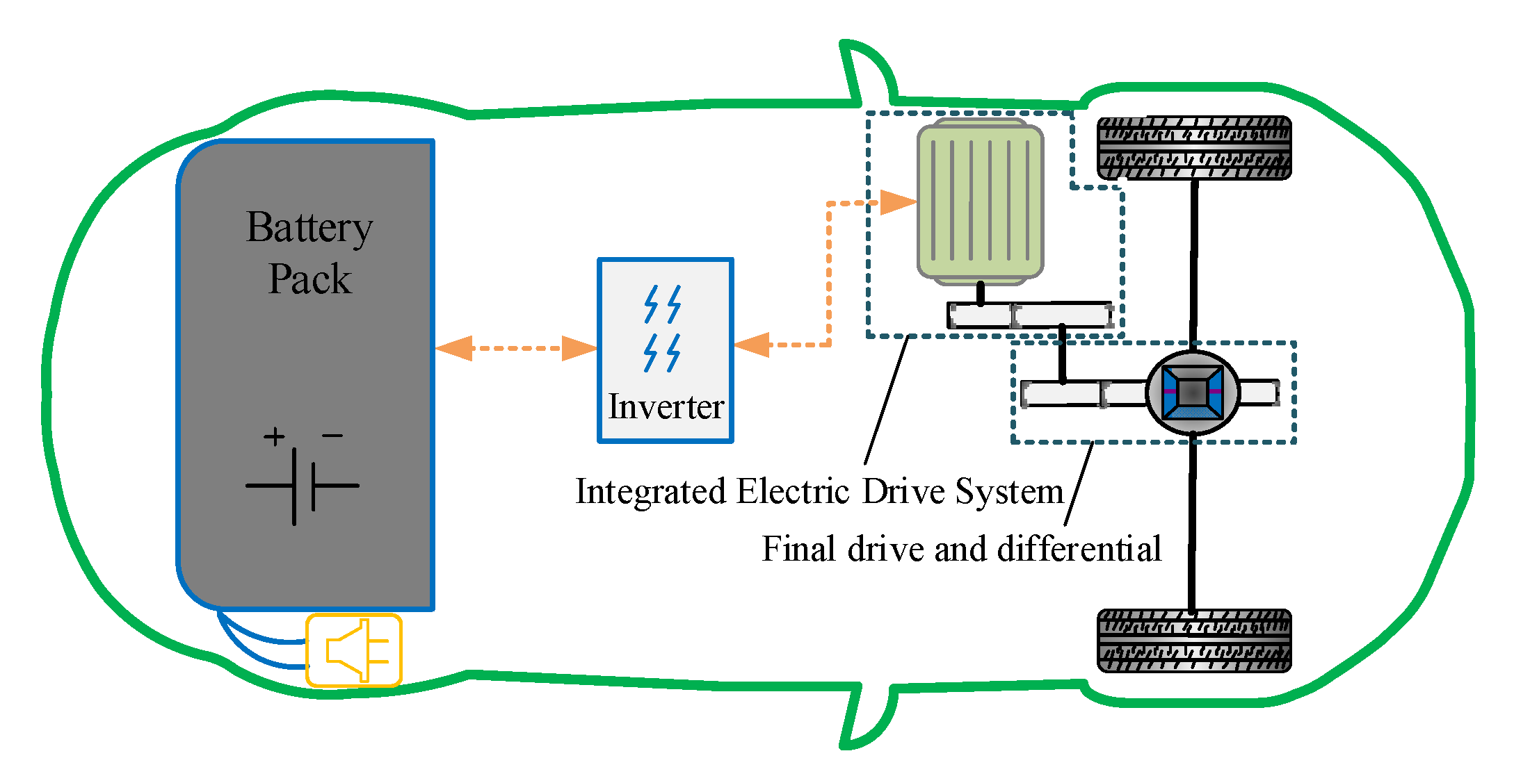
2. Dynamics Modeling of PEV Equipped with IEDS

The structure of a PEV equipped with an IEDS is shown in Figure 2. Its power transmission system mainly includes an IEDS, final drive, differential, axle shaft, and wheel. In order to study the influence of harmonic torque on the working performance of an IEDS, the transient models of the electrical system and mechanical transmission system of an IEDS are established in this paper. On this basis, the dynamic model of the PEV equipped with an IEDS is established.

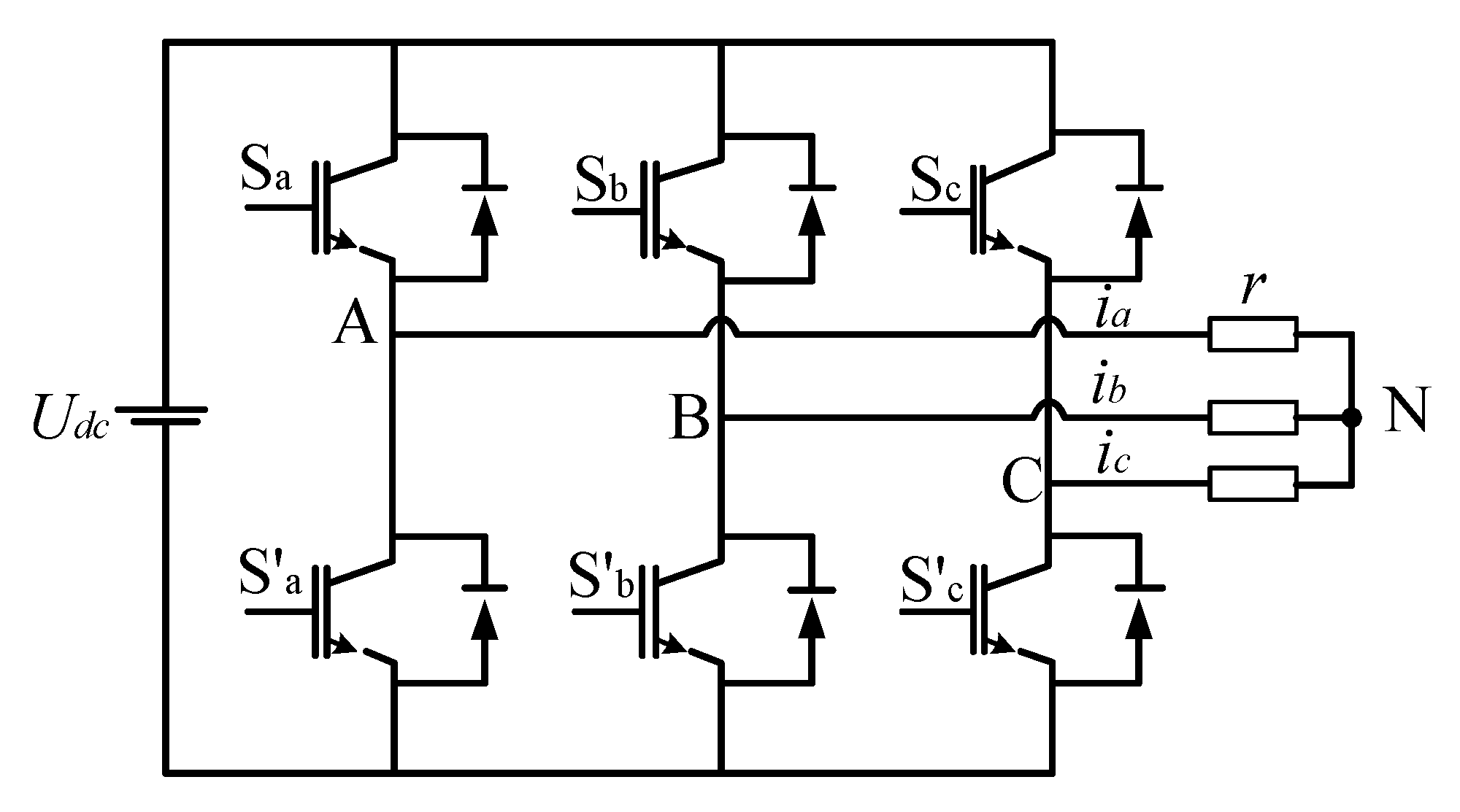
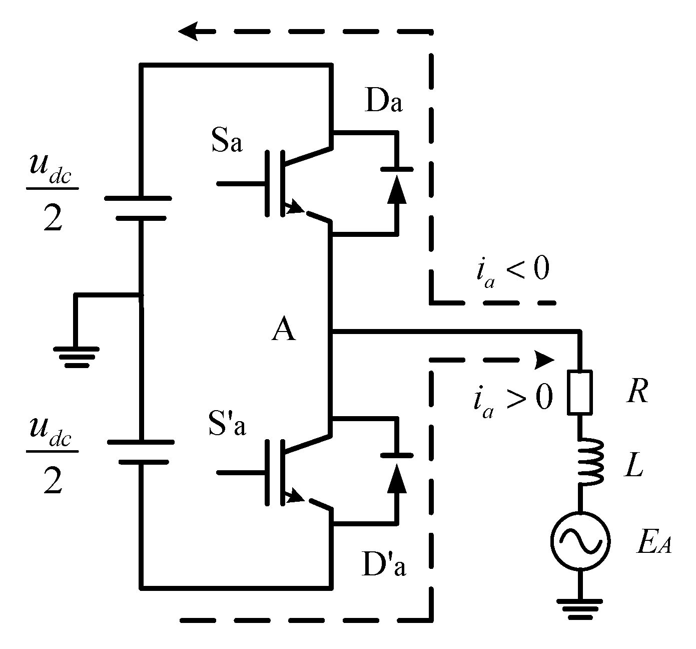
2.1. Harmonic Torque Mathematical Model of PMSM

Combined with Clarke transform and Park transform, the mathematical model of a three-phase PMSM in a d-q rotating coordinate system can be obtained. The stator voltage equation is as follows:
{ u d = R i d + L d d d t i d ω e L s i q u q = R i q + L q d d t i q + ω e ( L s i d + ψ f )
where ud and uq are the voltages of the d-axis and q-axis respectively; id and iq are the currents of the d-axis and q-axis respectively; Ld and Lq are the stator inductance of the d-axis and q-axis respectively; R is the stator resistance of the motor; and ωe is the rotor angular velocity.
The torque equation of a surface-mounted permanent magnet synchronous motor (SPMSM) is as follows:
T m = 3 2 P n i q [ i d ( L d L q ) + ψ f ] .
Stated thus, through the transformation from an a-b-c coordinate system to a d-q rotating coordinate system, the electromagnetic torque of PMSM is only related to its q-axis current. This means that by controlling the q-axis current of the motor, the electromagnetic torque control of the motor can be realized. The parameters of PMSM used in this paper are shown in Table 1.
The inverter circuit of the PMSM for an electric vehicle is shown in Figure 3. Sa, Sb, Sc, S’a, S’b, and S’c are defined as the switch states of the inverter. The working principle of the inverter is as follows: when Sa/Sb/Sc is in 1 state, S’a/S’b/S’c is in 0 state. At this time, the three switching devices of the upper bridge arm of the inverter circuit are on, while the three switching devices of the lower bridge arm of the inverter circuit are turned off.
Figure 4 shows a structural diagram of the A-phase bridge arm of the inverter, in which the switch device is an insulated gate bipolar transistor (IGBT), and the motor stator winding is equivalent to a resistance inductance circuit, forming a series structure with the voltage source. As shown in Figure 4, when the inverter switching device Sa is on, S’a must be turned off. If the speed of Sa is turning on faster than that of S’a is turning off, the bridge arm will be short-circuited. Therefore, in order to ensure the safe operation of the inverter, dead time Tdead should be added to the process of switching between the two switches. During the dead time, it can be equivalent to the switch of the upper or lower leg of the inverter being on. There is a deviation between the actual switch signal and the ideal switch driving signal, which leads to the deviation between the actual output voltage and the demand voltage.
The dead time in the actual output voltage waveform of the inverter can be expressed as follows:
T d = t d + t o n t o f f
where ton and toff represent the on time and off time of the IGBT respectively; while td represents the preset dead time in the switch driving signal.
The above content is the error voltage brought by the dead time of the inverter to the system. The switch tube voltage drop and freewheeling diode conduction voltage drop will also bring an error voltage to the system. As shown in Figure 5, the current direction and path in the inverter bridge arm are different under different switching states. The error voltage Uerr considering dead time and tube voltage drop is obtained by making a difference, as shown in Figure 5. vt is the conduction voltage drop of the switch tube, and vd is the conduction voltage drop of the freewheeling diode. Supposing that Ts1 and Ts2 are the real turn-on times of Sa and S’a of the upper and lower switches in the A-phase of the inverter respectively during a pulse width modulation (PWM) cycle, the average error voltage Δ u can be obtained by averaging the error voltage in a period of time according to the area equivalent principle. After averaging the error voltage over a period of time, a square wave signal can be obtained, as shown in Figure 6.
Through Fourier decomposition of the square wave signal, the mathematical expression of the average error voltage of the inverter can be obtained as follows:
u e r r = 4 Δ u π ( sin ω t + 1 3 sin 3 ω t + 1 5 sin 5 ω t + 1 7 sin 7 ω t + ) .
From the results of Fourier decomposition, it can be seen that the nonlinear characteristics such as the dead-time effect and voltage drop of the inverter will introduce a large number of harmonics into the motor voltage, then causing the motor to produce a harmonic current. Since the stator winding of the PMSM mostly adopts star connection mode, the 3rd and integral multiple harmonic components of the stator current can not be circulated. Therefore, the actual system mainly includes 5th, 7th, 11th, and 13th harmonic components [37]. The specific parameters of the inverter used in this paper are shown in Table 2.
In the a-b-c coordinate system, the rotation speed of the 5th harmonic voltage vector in the motor stator winding is −5ω, and the rotation speed of the 7th harmonic voltage vector in the motor stator winding is 7ω [38]. Therefore, the stator voltage equation in the three-phase static coordinate system can be expressed as follows:
{ u a = u 1 sin ( ω t + θ 1 ) + u 5 sin ( 5 ω t + θ 5 ) + u 7 sin ( 7 ω t + θ 7 ) + u b = u 1 sin ( ω t + θ 1 2 3 π ) + u 5 sin ( 5 ω t + θ 5 2 3 π ) + u 7 sin ( 7 ω t + θ 7 2 3 π ) + u c = u 1 sin ( ω t + θ 1 + 2 3 π ) + u 5 sin ( 5 ω t + θ 5 + 2 3 π ) + u 7 sin ( 7 ω t + θ 7 + 2 3 π ) +
where θ1 is the initial phase angle of the stator fundamental voltage; θ5 and θ7 are the initial phase angles of the 5th and 7th harmonic voltages of the stator, respectively; u1 is the amplitude of the stator fundamental voltage; and u5 and u7 are the amplitude of the 5th and 7th harmonic voltages of the stator, respectively.
Adopting the amplitude invariable transformation, the stator voltage equation expressed in Equation (5) is transformed into a d-q rotating coordinate system, and the converted stator voltage equation of the d-axis and q-axis is obtained as follows:
{ u d = u d 1 + u 5 cos ( 6 ω t + θ 5 ) + u 7 cos ( 6 ω t + θ 7 ) u q = u q 1 + u 5 sin ( 6 ω t + θ 5 ) + u 7 sin ( 6 ω t + θ 7 )
where ud1 and uq1 are the d-axis and q-axis components of fundamental voltage in the d-q rotating coordinate system, respectively.
It can be seen from Equation (6) that in the d-q rotating coordinate system, the 5th and 7th harmonic components on the stator of the motor in the original three-phase static coordinate system are shown as the 6th harmonic component, with the rotation directions of them being opposite. If there is harmonic voltage in the stator voltage, there will be a corresponding harmonic current. In the same way, transforming the three-phase current of the motor into the d-q rotating coordinate system by means of amplitude invariance, the stator current equation in the d-q rotating coordinate system is obtained as follows:
{ i d = i d 1 + i 5 cos ( 6 ω t + θ 5 ) + i 7 cos ( 6 ω t + θ 7 ) i q = i q 1 + i 5 sin ( 6 ω t + θ 5 ) + i 7 sin ( 6 ω t + θ 7 )
where id1 and iq1 represent the d-axis and q-axis components of the stator fundamental current in the d-q rotating coordinate system; i5 and θ5 represent the amplitude and initial phase angle of the 5th harmonic current in the d-q rotating coordinate system; and i7 and θ7 represent the amplitude and initial phase angle of the 7th harmonic current of the motor in the d-q rotating coordinate system.
Ignoring the harmonic caused by the motor itself, there is no harmonic flux component in the permanent magnet flux linkage. By substituting Equation (7) into Equation (1), the stator voltage equation with harmonic component is obtained as follows:
{ u d = ω e L s i q 1 + R i d 1 + 5 ω e L s i 5 sin ( 6 ω t + θ 5 ) + R i 5 cos ( 6 ω t + θ 5 ) 7 ω e L s i 7 sin ( 6 ω t + θ 7 ) + R i 7 cos ( 6 ω t + θ 7 ) u q = ω e ψ f + ω e L s i d 1 + R i q 1 5 ω e L s i 5 cos ( 6 ω t + θ 5 ) + R i 5 sin ( 6 ω t + θ 5 ) + 7 ω e L s i 7 cos ( 6 ω t + θ 7 ) + R i 7 sin ( 6 ω t + θ 7 ) .
Projecting the fundamental current and harmonic current of the motor into the d-q rotating coordinate system, the current in the d-q axis is obtained as follows:
{ i d = i d 1 + i d 5 + i d 7 + i d 11 + i d 13 i q = i q 1 + i q 5 + i q 7 + i q 11 + i q 13
where id1 is the d-axis component of the stator fundamental current; i′d5, i′d7, i′d11, and i′d1 are the d-axis components of the stator harmonic current of 5th, 7th, 11th, and 13th harmonic currents, respectively; iq1 is the q-axis component of the stator fundamental current; and i′q5, i′q7, i′q11, and i′q13 are the q-axis components of the stator harmonic current of the 5th, 7th, 11th, and 13th harmonic currents, respectively.
By introducing Equation (9) into the electromagnetic torque equation of the motor, the harmonic equation of the torque is obtained as follows:
T m = 3 2 P n ψ f i q = 3 2 P n ψ f [ i q 1 + ( i q 5 + i q 7 ) + ( i q 11 + i q 13 ) ] = T e 0 + T e 6 + T e 12
where Te0 is the constant component of electromagnetic torque; and Te6 and Te12 are the 6th and 12th harmonics of the electromagnetic torque respectively.
It can be seen from Equation (10) that the constant component of electromagnetic torque is generated by the interaction of fundamental current and permanent magnet flux linkage under the premise of ignoring the harmonics introduced by the motor. The 6th harmonic of electromagnetic torque is mainly generated by the interaction of the rotor flux and stator 5th and 7th harmonic currents. Similarly, the 12th harmonic of electromagnetic torque is mainly generated by the interaction of the rotor flux and stator 11th and 13th harmonic currents. Generally, the larger the harmonic number, the smaller the corresponding harmonic torque amplitude becomes.

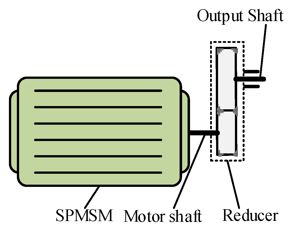
2.2. Transmission System Model of IEDS

The mechanical transmission system of an IEDS mainly includes a wheel gear reducer and output shaft. The dynamic model of a helical gear transmission system is established as below.
The meshing displacement of the gear tooth along the meshing line is:
δ y = R 1 θ 1 R 2 θ 2 e
where θ1 is the angular displacement of gear 1; θ2 is the angular displacement of driven gear 2; R1 is the radius of gear 1; R2 is the radius of gear 2; and e is the meshing error.
The normal elastic deformation of the fear tooth along the contact line is as follows:
δ i = δ y cos β b
where βb is the helix angle of the base circle.
The meshing force of the gear pair can be expressed as follows:
F m = c m δ · i + k m δ i = [ c m ( R 1 θ · 1 R 2 θ · 2 e · ) + k m ( R 1 θ 1 R 2 θ 2 e ) ] cos β b
where cm is the gear meshing damping and km is the gear meshing stiffness. The calculation methods of the two will be described in detail later.
The y-direction meshing force of the gear pair can be expressed as follows:
F y = F m cos β b = [ c m ( R 1 θ · 1 R 2 θ · 2 e · ) + k m ( R 1 θ 1 R 2 θ 2 e ) ] cos 2 β b .
The torsional vibration model of a parallel shaft helical cylindrical gear pair is as follows:
{ I 1 θ · · 1 = T 1 F y R 1 I 2 θ · · 2 = T 2 + F y R 2
where I1 is the moment of inertia of gear 1; I2 is the moment of inertia of gear 2; T1 is the active torque acting on gear 1; and T2 is the load torque acting on gear 2.
The specific parameters of helical gears involved in this paper are shown in Table A1 of Appendix A. By calculating the length change of the meshing line in the process of gear meshing and describing the time-varying meshing stiffness of the helical gear by the angular displacement of the driving gear, the relationship between the stiffness and angular displacement of the driving gear is obtained, as shown in Figure 7.
The meshing damping of the gear pair can be expressed as follows:
c m = 2 ξ m k ¯ 12 m 1 m 2 m 1 + m 2
where ξ m is the meshing damping ratio in the range of 0.03–0.17; and mi is the mass of gear i.
The mathematical expression of the gear meshing error is as follows:
e = e m + e r sin ( Z 1 θ 1 + δ )
where em is the constant value of the meshing error, and er is the amplitude of the meshing error, both of which are related to the manufacturing accuracy of the gear; and δ is the initial phase of the meshing error.

2.3. Vehicle Powertrain Model

The moment of inertia of the whole vehicle is equivalent to the wheel in this paper, and the torsional vibration model of the whole vehicle powertrain is obtained, as shown in Figure 8. Ignoring the translational vibration of the system, a 6-DOF dynamic model of the power transmission system is established by using the lumped parameter method, as shown in Equation (18).
{ I m θ · · m + c s 1 ( θ · m θ · 1 ) + k s 1 ( θ m θ 1 ) = T m I 1 θ · · 1 c s 1 ( θ · m θ · 1 ) k s 1 ( θ m θ 1 ) + R 1 F y = 0 I 2 θ · · 2 + c s 2 ( θ · 2 θ · g ) + k s 2 ( θ 2 θ g ) R 2 F y = 0 I g θ · · g c s 2 ( θ · 2 θ · g ) k s 2 ( θ 2 θ g ) + 2 / i 0 · c a ( θ · g / i 0 θ · w ) + 2 / i 0 · k a ( θ g / i 0 θ w ) = 0 I w θ · · w c a ( θ · g / i 0 θ · w ) k a ( θ g / i 0 θ w ) + c w ( θ · w θ · V ) + k w ( θ w θ V ) = 0 I V θ · · V 2 c w ( θ · w θ · V ) 2 k w ( θ w θ V ) = T L
where Tm is the electromagnetic driving torque generated by PMSM; and TL is the external resistance load when the vehicle is working. The parameters and their values represented by other symbols are shown in Table A2 of Appendix A.
Among them, the resistance load of the vehicle can be expressed as follows:
T L = ( m g f cos α + C D A 21.15 V 2 + m g sin α ) · r
where r is the wheel radius of the car.

3. Research on Electromechanical Coupling Characteristics of IEDS

In order to study the electromechanical coupling effect of an IEDS, the transmission system dynamic model, PMSM, and PMSM control system model are built in this paper. The speed and torque of the motor shaft are used as common variables to transfer data between the electrical system and mechanical system in real time. Figure 9 shows the electromechanical coupling model of a PEV in motor torque mode. It should be noted that the simulation model of the IEDS is built on the MATLAB/Simulink 2018b simulation platform and the computer processor is Intel(R) Core(TM) i7-8700 CPU@ 3.20 Ghz.
In order to explore the electromechanical coupling characteristics of an IEDS under the condition of uniform speed, the simulation conditions are set as: the speed of PMSM is 1000 rpm; the vehicle load is 100 Nm; and the motor working mode is torque control mode. When the speed of the PMSM is 1000 rpm (the rotation frequency is 16.67 Hz), the electric angular frequency of the motor is 66.67 Hz, and the gear meshing frequency of the reducer of the IEDS is 283.33 Hz. The electromagnetic torque and its frequency spectrum of the PMSM are shown as Figure 10a,b, respectively. Under the influence of nonlinear factors such as inverter dead-time effect and voltage drop effect, the electromagnetic torque shows the characteristics of pulsation. Moreover, the fluctuation range of harmonic torque is about 11 Nm, and the fluctuation frequencies of harmonic torque are mainly 400 Hz, 800 Hz, and 1200 Hz, which are 6 times, 12 times, and 18 times the angular frequency, respectively. Figure 11a shows the three-phase current of the PMSM, and it can be seen that the current waveform in the time domain is not completely sinusoidal. The frequency domain analysis of the A phase current in three-phase current by fast Fourier transform (FFT) shows that in addition to the fundamental frequency (67 Hz), the current also contains harmonic currents, among which the obvious components are 333 Hz, 467 Hz, 733 Hz, and 867 Hz, which are 5 times, 7 times, 11 times, and 13 times the angular frequency, respectively, as shown in Figure 11b.
The shaft speed and the frequency spectrum of the PMSM are shown as Figure 12a,b, respectively. Under the influence of harmonic torque, gear time-varying stiffness, gear meshing error, and other factors, the motor shaft speed fluctuates continuously, and the fluctuation amplitude is about 2 rpm. The main components of the motor shaft speed fluctuation are gear meshing frequency (283 Hz), 2nd gear meshing frequency (567 Hz), motor 6th harmonic torque (400 Hz), and 12th harmonic torque (800 Hz). The gear pair speed and the frequency spectrum of the reducer in the IEDS are shown in Figure 13, which shows that the speed of the driving and driven gears fluctuates constantly, and the main frequency component of fluctuation is the same as that of the motor shaft. In conclusion, under the influence of mechanical transmission system factors such as gear time-varying stiffness and gear meshing error, the rotational speed of each component of the IEDS presents the characteristics of fluctuation. Meanwhile, the harmonic torque of the motor introduces more harmonics to the speed of each component, which intensifies the speed fluctuation of each component.
The meshing force and the frequency spectrum of the gear pair of the reducer in the IEDS is shown in Figure 14, and the meshing displacement and its frequency spectrum is shown in Figure 15. Under the influence of time-varying meshing stiffness and meshing error, the meshing force fluctuates around the theoretical meshing force. The frequency domain analysis of the gear meshing force and meshing displacement not only includes the gear meshing frequency (283 Hz) and its 2nd harmonic frequency (567 Hz), but it also includes the 6th harmonic torque (400 Hz) and the 12th harmonic torque (800 Hz). The dynamic transfer torque and the frequency spectrum of the motor shaft are shown in Figure 16, and that of the output shaft of the IEDS is shown in Figure 17. The dynamic torque transmitted by the two shafts also fluctuates continuously. It can be seen from the frequency domain analysis diagram that the main component of the fluctuation is the same as the meshing force of the gear.
Through the above simulation and analysis of the electromechanical coupling characteristics of the IEDS under uniform speed conditions, it is found that the electrical system and mechanical system of the IEDS will affect each other. Gear meshing frequency is the main component of motor shaft speed fluctuation, which means that mechanical nonlinear factors such as time-varying meshing stiffness and meshing error are the main causes of motor shaft speed fluctuation. Besides, the electrical system will also affect the operation of mechanical system, because the dead-time effect and voltage drop effect of the inverter make the output electromagnetic torque of the PMSM contain 6th and 12th harmonics. The harmonic torque frequency of the motor is included in the meshing force of the gear and the transmission torque of the shaft, which means that the harmonic torque of the motor will increase the dynamic load of the mechanical system.
It should be noted that when designing an IEDS, if the 6th harmonic torque of the motor is consistent with the gear meshing frequency, the amplitude of the motor speed fluctuation may be larger after superposition, which is not conducive to the smooth operation of the motor. Moreover, the dynamic load amplitude of the mechanical system is larger and the service life of the mechanical system is reduced. So, in order to avoid it, the gear meshing frequency of the reducer should not be equal to 6 times that of the electric angular frequency of the motor, namely Z p 1 6 P n (where Z p 1 is the number of driving gear teeth of the reducer gear pair; and Pn is the number of magnetic pole pairs).

4. Harmonic Torque Reduction Strategy for IEDS

According to the analysis above, the harmonic torque will cause additional load fluctuation in an IEDS, which will aggravate the speed fluctuation of each component of the IEDS, and that is not conducive to the stable and efficient operation of the system. To solve the above problems, a harmonic torque reduction strategy to reduce the adverse effects of motor harmonic torque in an IEDS is proposed this section.

4.1. Design of Harmonic Torque Reduction Strategy

The stator of the motor mainly contains the 5th and 7th harmonic currents. In the three-phase static coordinate system, the rotation speed of the 5th harmonic current is −5ω, and the rotation speed of the 5th harmonic current is 7ω. To better control the 5th and 7th harmonic currents of the motor, the 5th and 7th rotation coordinate systems are established in this section. Through coordinate transformation, the 5th harmonic voltage and current are converted into DC flow in the 5th rotation coordinate system, while the 7th harmonic voltage and current are converted into DC flow in the 7th rotation coordinate system. In a relative manner, other current components are converted into AC flow.
Consequently, at this time, a low-pass filter can be used to separate the 5th and 7th harmonics in the three-phase current of PMSM, and then the synchronous rotation a proportional-integral (PI)controller can be used to make the actual d-q axis current follow the reference current command to realize the injection of harmonic voltage to eliminate the torque harmonic component.
The 5th and 7th synchronous rotation coordinate systems used in Figure 18 are shown in Figure 19. It should be noted that the transformation matrix between the coordinate systems is shown in Appendix B.
Based on the above coordinate transformation, Equation (8) is transformed into a 5th d-q rotating coordinate system:
{ u d 5 = ω e ψ f sin ( 6 ω t + θ 0 ) ω e L s i 1 sin ( 6 ω t + θ 1 ) + R i 1 cos ( 6 ω t + θ 1 ) + 5 ω e L s i q 5 + R i d 5 7 ω e L s i 7 sin ( 12 ω t + θ 7 ) + R i 7 cos ( 12 ω t + θ 7 ) u q 5 = ω e ψ f cos ( 6 ω t + θ 0 ) + ω e L s i d 1 cos ( 6 ω t + θ 1 ) + R i 1 sin ( 6 ω t + θ 1 ) 5 ω e L s i d 5 + R i q 5 + 7 ω e L s i 7 cos ( 12 ω t + θ 7 ) + R i 7 sin ( 12 ω t + θ 7 )
where id5 and iq5 are the d-axis and q-axis DC current components in the 5th d-q rotation coordinate system.
The harmonic steady-state voltage equation in the 5th d-q rotating coordinate system is obtained by omitting the AC quantities contained in Equation (20), which is written as:
{ u d 5 = 5 ω L q i q 5 + R i d 5 u q 5 = 5 ω L q i q 5 + R i d 5 .
Similarly, Equation (8) is transformed into the 7th d-q rotating coordinate system:
{ u d 7 = ω e ψ f sin ( 6 ω t + θ 0 ) ω e L s i 1 sin ( 6 ω t + θ 1 ) + R i 1 cos ( 6 ω t + θ 1 ) + 5 ω e L s i 5 sin ( 12 ω t + θ 5 ) + R i 5 cos ( 12 ω t + θ 5 ) 7 ω e L s i q 7 + R i d 7 u q 7 = ω e ψ f cos ( 6 ω t + θ 0 ) + ω e L s i 1 cos ( 6 ω t + θ 1 ) + R i 1 sin ( 6 ω t + θ 1 ) 5 ω e L s i 5 cos ( 12 ω t + θ 5 ) + R i 5 sin ( 12 ω t + θ 5 ) + 7 ω e L s i d 7 + R i q 7
where id7 and iq7 are the d-axis and q-axis DC current components in the 7th d-q rotation coordinate system.
The harmonic steady-state voltage equation in the 7th d-q rotating coordinate system is obtained by omitting the AC quantities contained in Equation (22), which is written as:
{ u d 7 = 7 ω L q i q 7 + R i d 7 u q 7 = 7 ω L q i q 7 + R i d 7
Using a PI controller, combined with the 5th and 7th harmonic steady-state voltage equations, the harmonic current loop control strategy is obtained, as shown in Figure 20a,b. Among them, the 5th and 7th harmonic steady-state voltage and current are coupled with each other. In order to better control the harmonic current, this paper realizes the decoupling of stator harmonic voltage and current by adding compensation terms. Superimposing the voltage generated by the harmonic voltage steady-state equation and the harmonic current PI controller, the required injection voltage of each harmonic current in the rotating coordinate system can be obtained.
As shown in Figure 21, after coordinate transformation, injecting the harmonic output from the harmonic current controller into voltage signal U α and U β and then adding them to the required voltage U α * and U β * of the motor itself, harmonic voltage injection is realized, which constitutes the new reference voltage signals U β and U β of the motor as the inverter demand voltages.

4.2. Simulation Analysis of Harmonic Torque Reduction Control Strategy Effectiveness

The electromechanical coupling dynamic model of a PEV with a harmonic torque reduction strategy is shown in Figure 22. In order to verify the effect of the harmonic torque reduction strategy, the simulation conditions are set as: the speed of the PMSM is 1000 rpm; the load of the vehicle is 100 Nm; and the motor is in torque control mode.
Figure 23a,b show the three-phase current before and after adding the harmonic reduction strategy, respectively, while Figure 23c,d show the frequency domain analysis of the three-phase current before and after adding the harmonic reduction strategy, respectively. Moreover, Figure 24a,b show the electromagnetic torque of the motor before and after adding the harmonic reduction strategy, respectively, while Figure 24c,d show the frequency domain analysis of the motor electromagnetic torque before and after adding the harmonic reduction strategy, respectively. Under the effect of the harmonic reduction strategy, the 5th and 7th harmonics in the current are significantly reduced. Furthermore, the sinusoidal degree of the current is significantly improved, and the 6th harmonic torque of the motor is effectively reduced. It can be found that the amplitude of the 5th harmonic current is reduced from 1.234 A to 0.06 A, and that of the 7th harmonic current is reduced from 0.214 A to 0.006 A. Meanwhile, the total fluctuation amplitude of electromagnetic torque is reduced by 50% from 10 Nm to 5 Nm. The 6th harmonic torque amplitude of the motor is reduced from 2.909 Nm to 0.060 Nm. From the analysis of the above results, it can be seen that the harmonic current content can be effectively reduced by harmonic voltage injection, and then the harmonic torque can be reduced.
Figure 25a compares the motor shaft speed before and after adding the harmonic reduction strategy while Figure 25b,c show the frequency domain analysis of the motor shaft speed before and after adding the harmonic reduction strategy, respectively. The fluctuation amplitude of the motor shaft speed caused by the 6th harmonic torque of motor is reduced from 0.25 to 0.01 rpm, which means that the overall fluctuation amplitude of the motor speed is effectively reduced.
Figure 26a compares the driving gear speed of the reducer of the IEDS before and after adding the harmonic reduction strategy, while Figure 26b,c shows the frequency domain analysis of the reducer driving gear speed before and after adding the harmonic reduction strategy, respectively. The results show that the fluctuation amplitude of the driving gear speed caused by the 6th harmonic torque of the motor is reduced from 0.44 to 0.01 rpm.
Moreover, Figure 27a compares the driving gear speed of the reducer of IEDS after adding the harmonic reduction strategy, while Figure 27b,c respectively show the frequency domain analysis of the driven gear speed of the reducer before and after adding the harmonic reduction strategy. It can be seen that the fluctuation amplitude of the driven gear speed caused by the 6th harmonic torque of the motor decreases from 0.33 to 0.01 rpm, and the overall fluctuation amplitude of the driven gear speed decreases slightly. Under the effect of the harmonic reduction strategy, the 6th harmonic torque component of the motor speed harmonics of each component of the IEDS is significantly reduced, and the fluctuation amplitudes of the speed of each component are reduced to a certain extent, which is conducive to the smooth operation of the system.
The meshing force of the reducer gear pair of the IEDS before and after adding the harmonic reduction strategy is shown in Figure 28a, while the frequency domain analysis of the meshing force of the gear pair before and after adding the harmonic reduction strategy is shown in Figure 28b,c respectively. It can be found that the amplitude of the gear pair meshing force caused by the 6th harmonic torque of motor is reduced from 26.09 to 0.67 Nm. Figure 29a compares the dynamic transmission torque of the motor shaft of the IEDS before and after adding the harmonic reduction strategy; then, Figure 29b,c show the frequency domain analysis of the motor shaft dynamic transmission torque before and after adding the harmonic reduction strategy, respectively. The amplitude of the motor shaft dynamic transmission torque caused by the 6th harmonic torque of the motor decreases from 0.64 to 0.02 Nm. Figure 30a compares the dynamic transmission torque of the output shaft of the IEDS before and after adding the harmonic reduction strategy. Then, Figure 30b,c show the frequency domain analysis of the output shaft dynamic transmission torque before and after adding the harmonic reduction strategy. The dynamic transmission torque of the output shaft caused by the 6th harmonic torque of the motor is reduced from 0.92 to 0.02 Nm. That is to say, under the effect of the harmonic reduction strategy, the 6th harmonic torque component of the dynamic load of each component of the IEDS is significantly reduced, which is conducive to improving the reliability of the system and prolonging the service life of the mechanical system.
The detailed data comparison of IEDS before and after the harmonic torque reduction strategy is shown in Table 3. The simulation results show that the 5th and 7th harmonic currents of the PMSM are obviously reduced under the action of the harmonic torque reduction strategy, which makes the 6th harmonic torque successfully reduced, thus reducing the speed fluctuation of each component of the IEDS and making the system run more stably. At the same time, the reduction of harmonic current also helps reduce the motor heating and improve the efficiency of the motor.

5. Conclusions

In this paper, the electromechanical coupling model of an electric vehicle equipped with an IEDS is established, and the electromechanical coupling characteristics of the IEDS are simulated and analyzed. On this basis, the method to suppress the harmonic torque of a PMSM is studied. There are two points that should be noted:
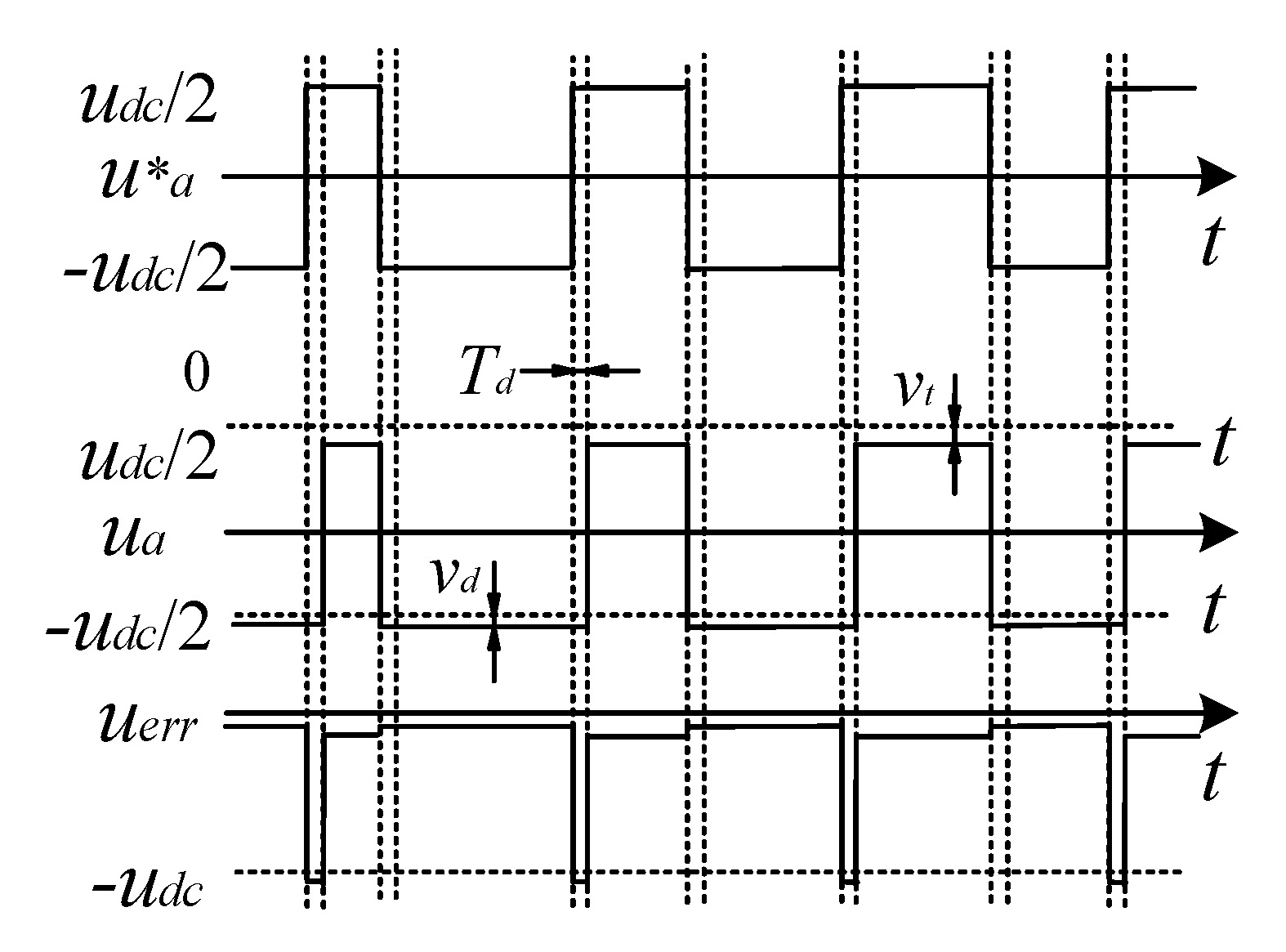
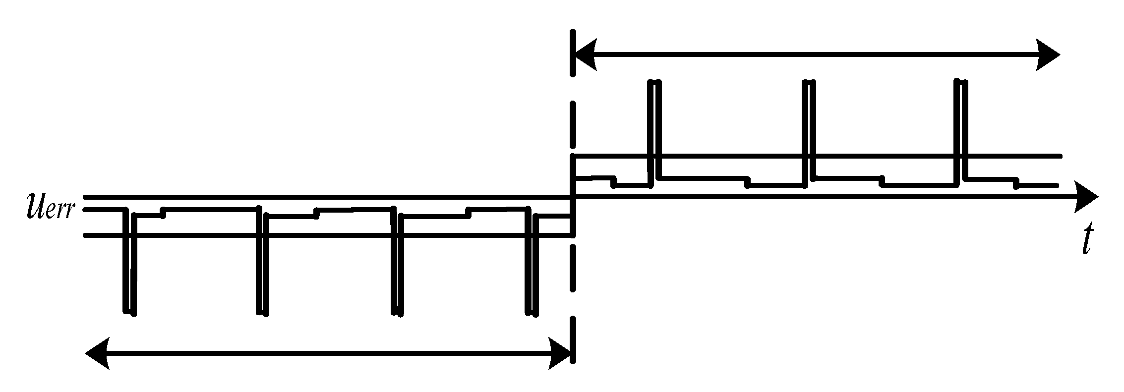
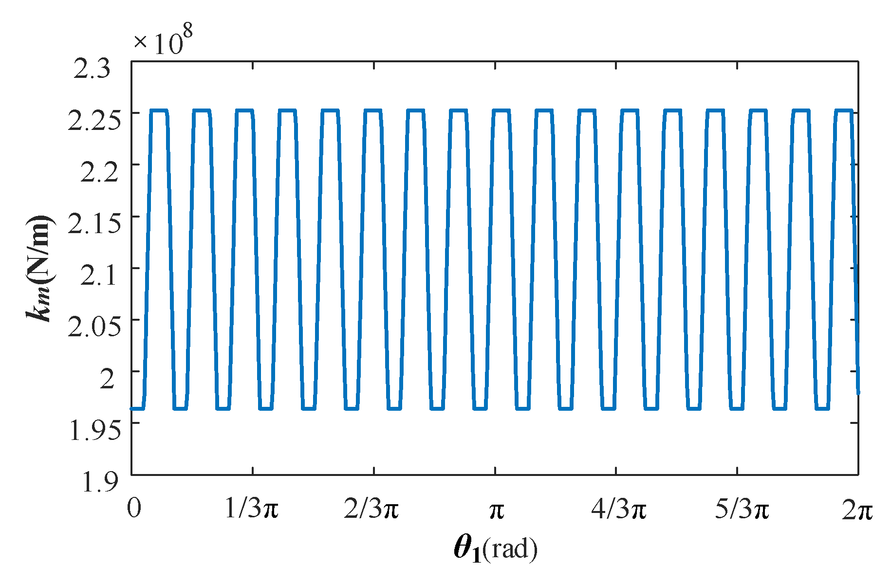
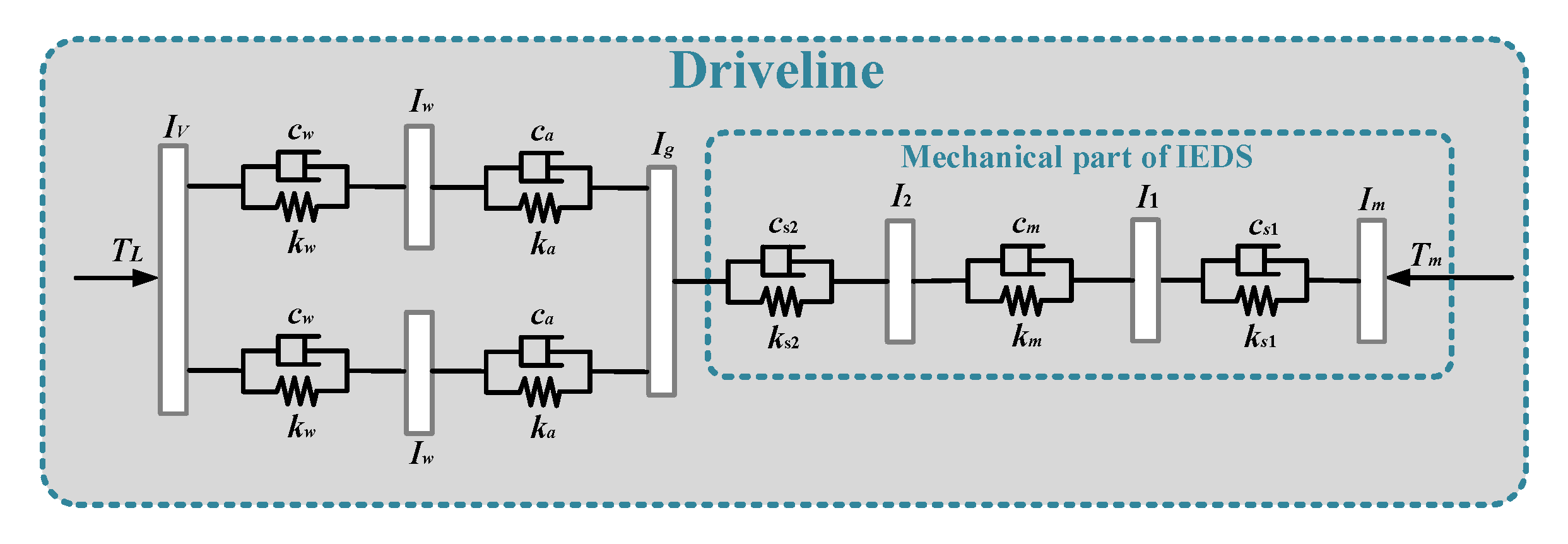
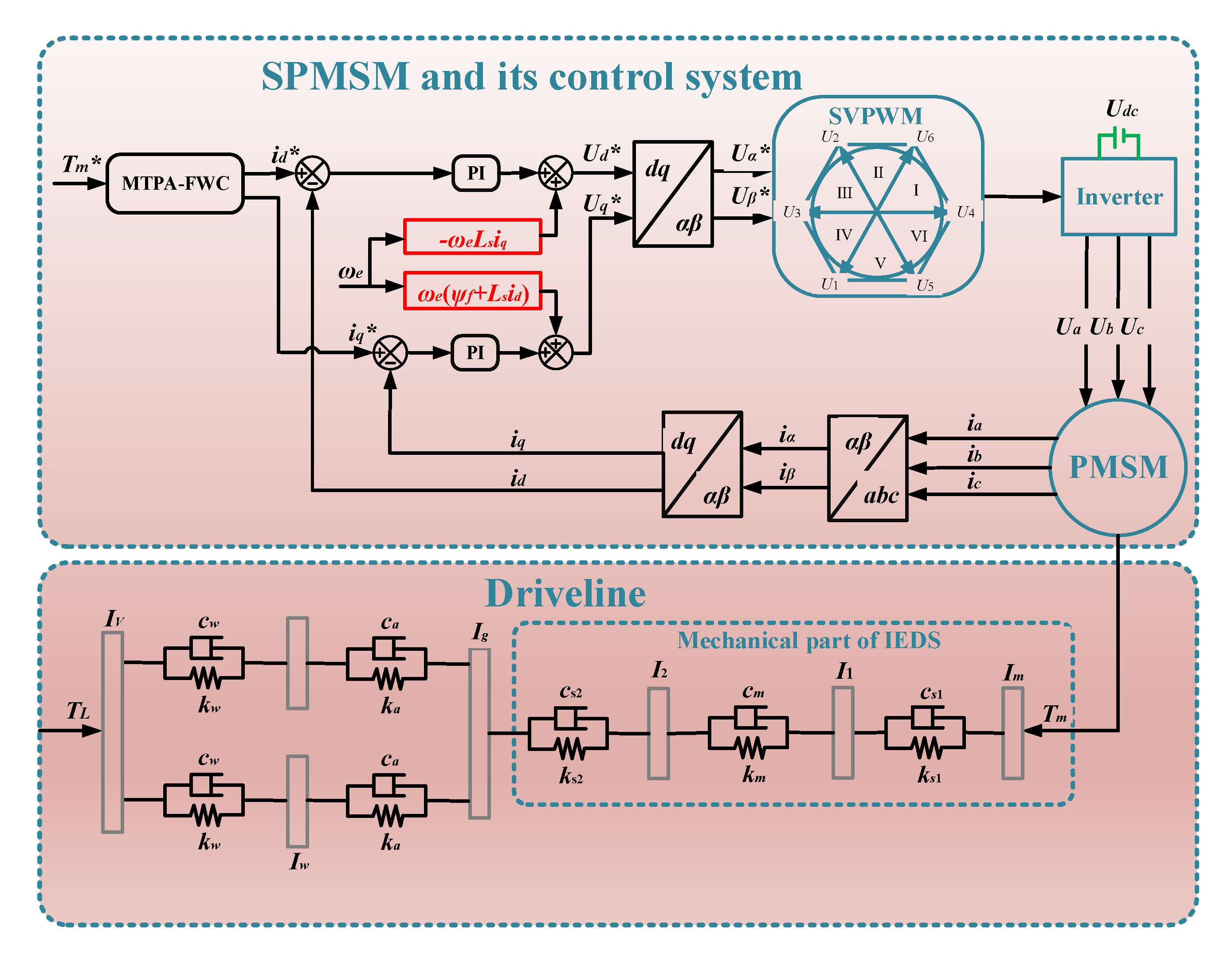
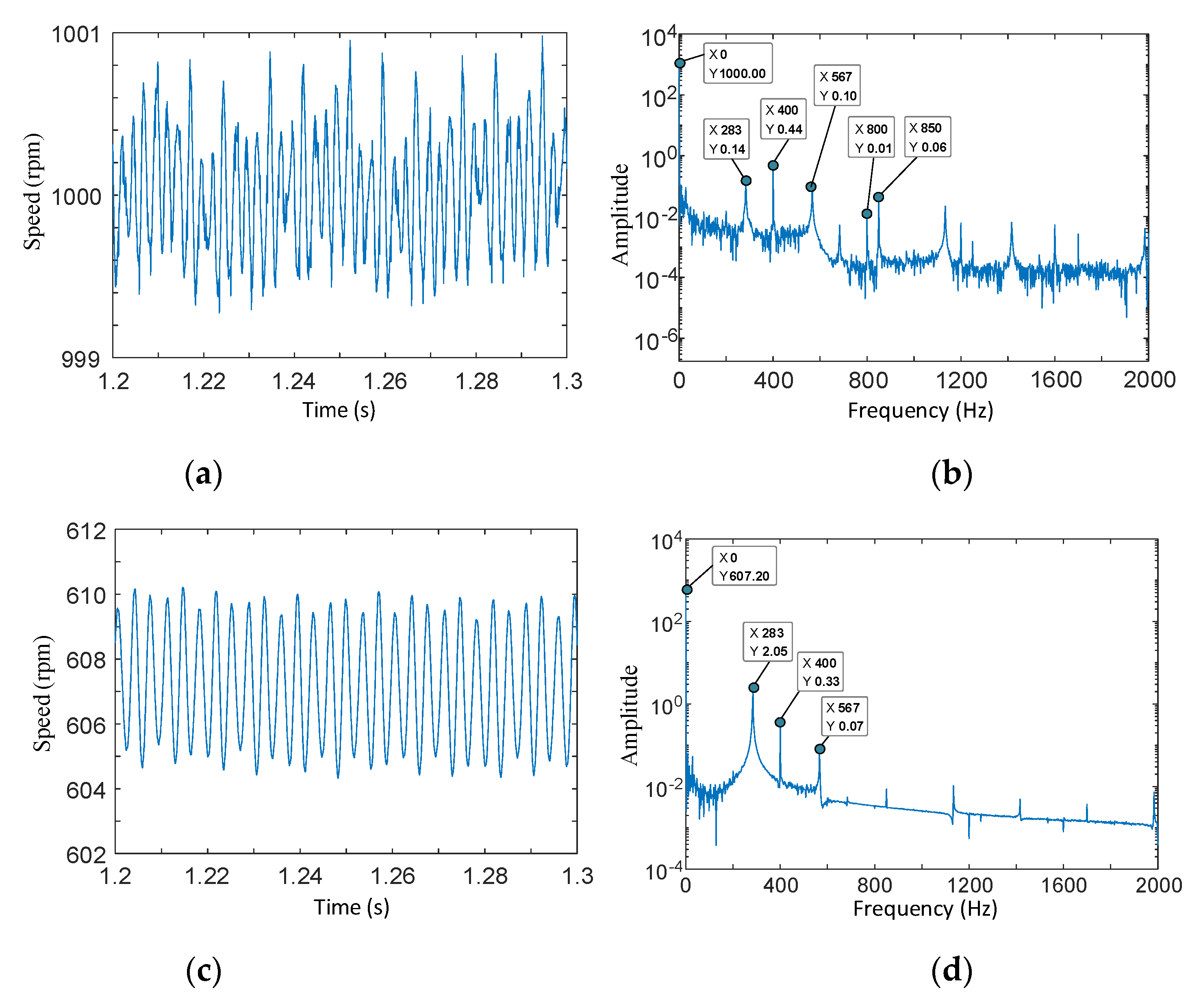
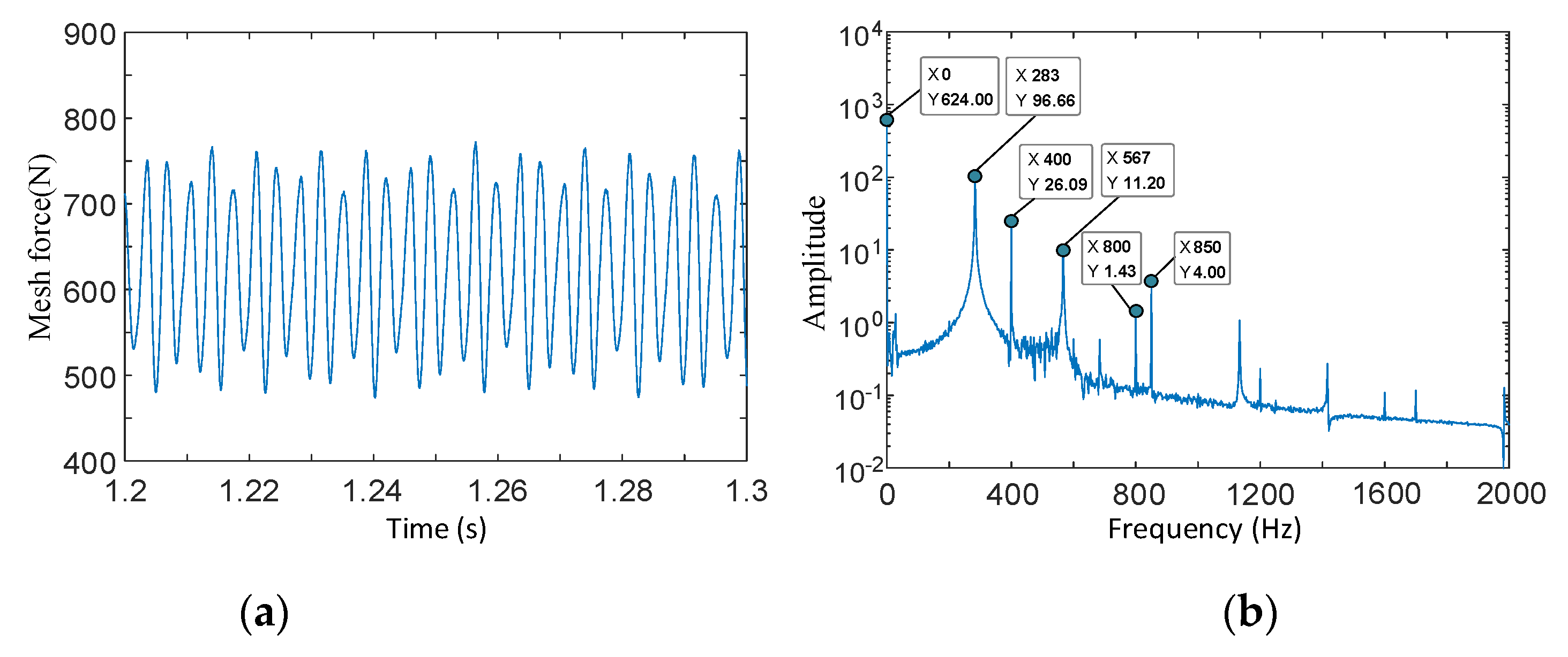
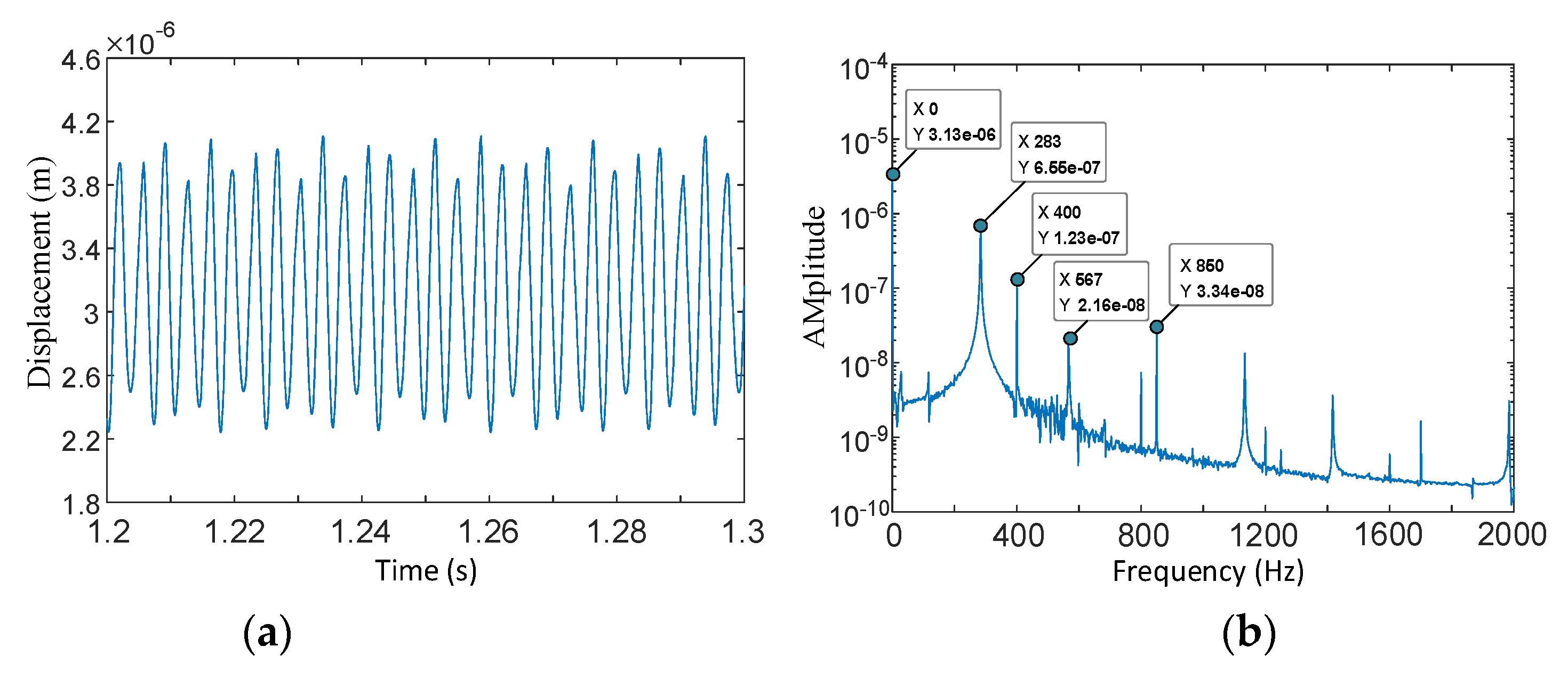
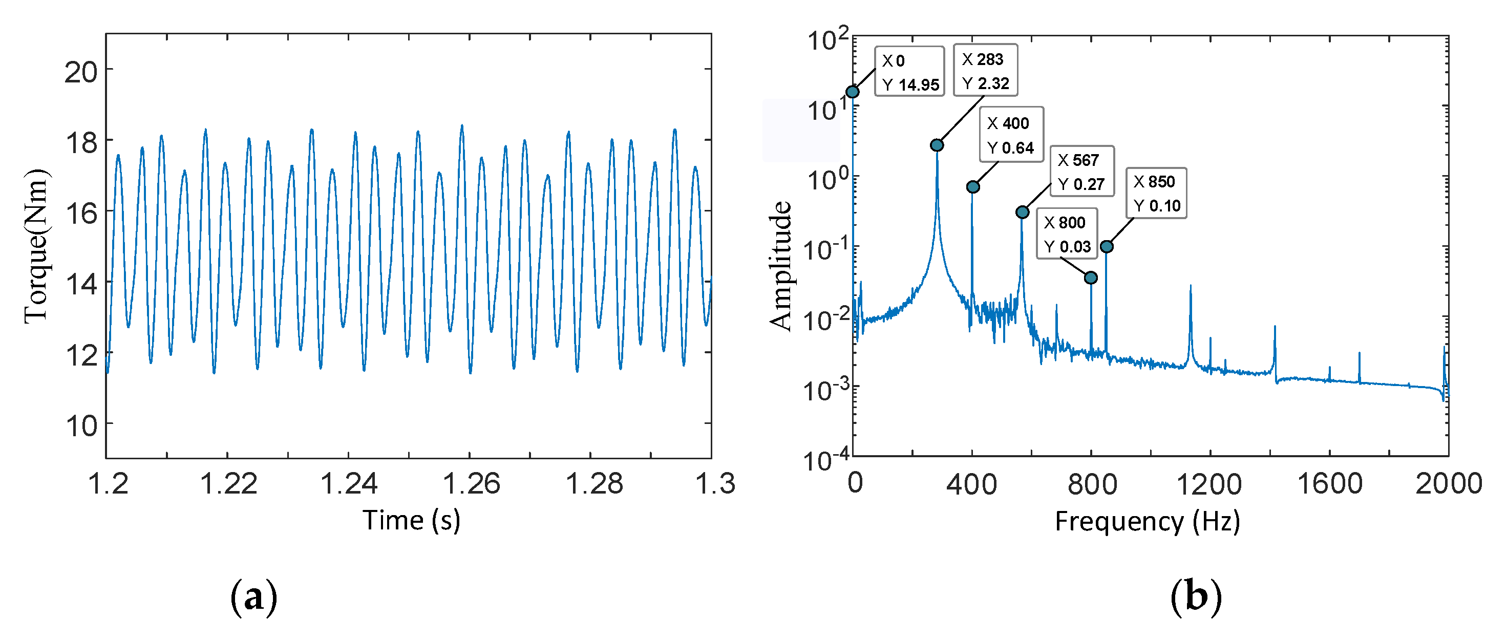
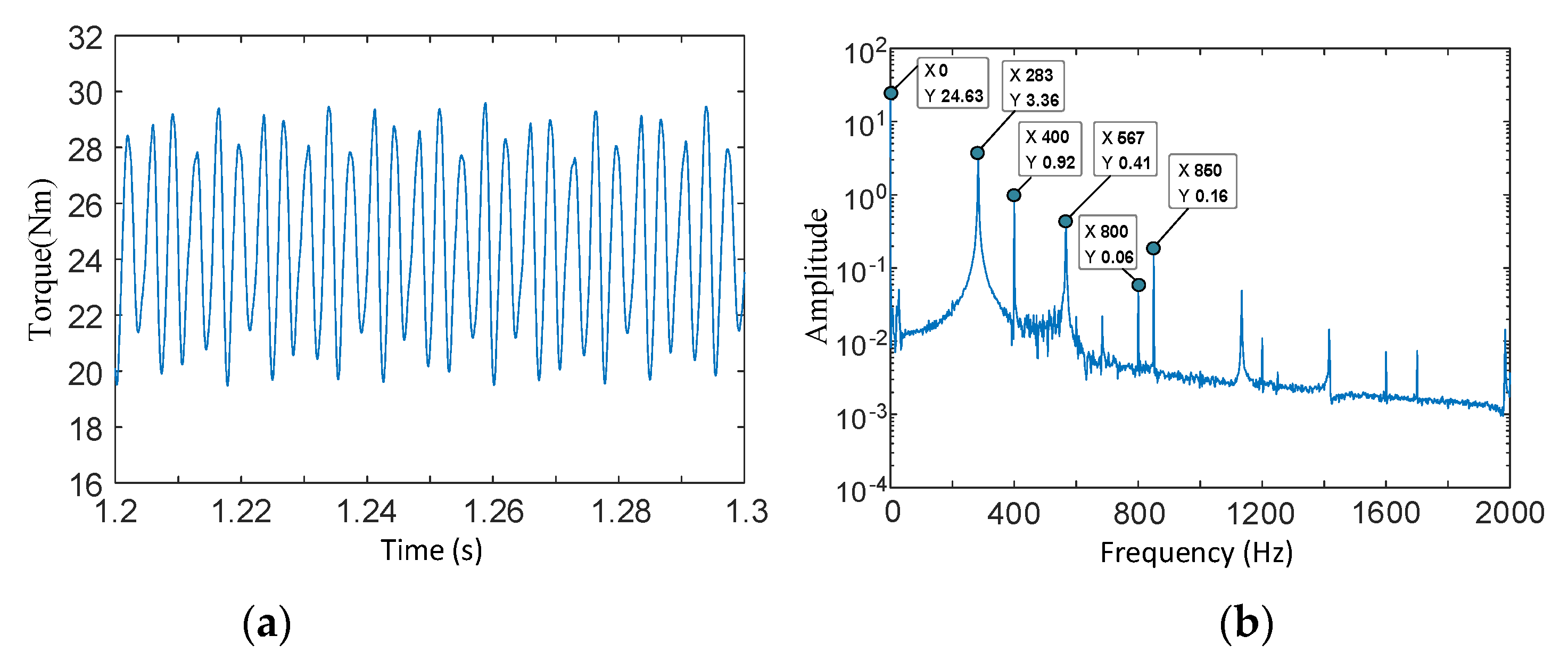
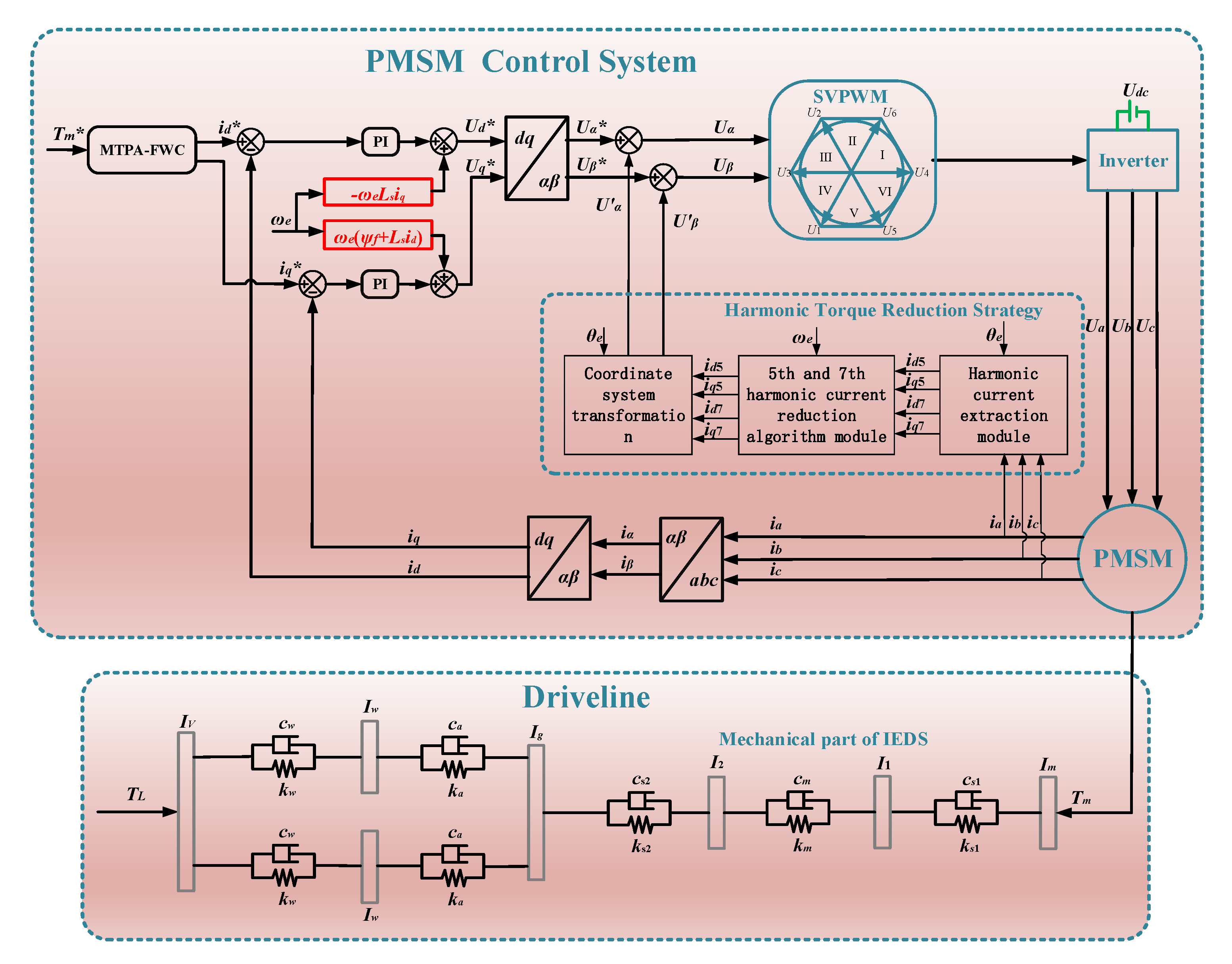
  • The electrical system and mechanical system of the IEDS will interact with each other. Mechanical nonlinear factors such as time-varying meshing stiffness and the meshing error of the gears can lead to a speed fluctuation of the motor shaft. Meanwhile, the dead-time effect and voltage drop effect of the inverter will cause the 6th harmonic torque and 12th harmonic torque of the motor, which will increase the dynamic load of the mechanical system. When designing an IEDS, the gear meshing frequency of the reducer should not be equal to 6 times that of the electric angular frequency of the motor, namely Z p 1 6 P n . In order to avoid that when the 6th harmonic torque of the motor is always consistent with the gear meshing frequency, the superposition may lead to a more serious speed fluctuation of the system, resulting in a greater dynamic load amplitude of the mechanical system and reducing the service life of the mechanical system.
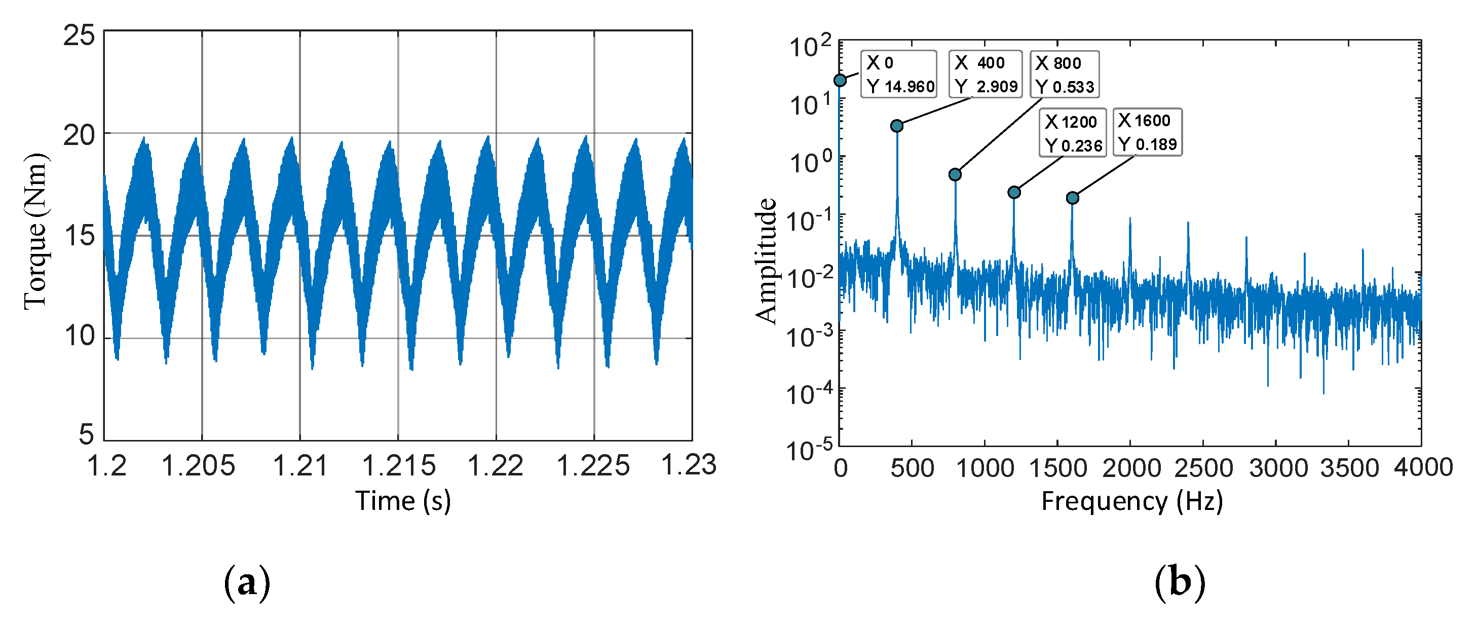
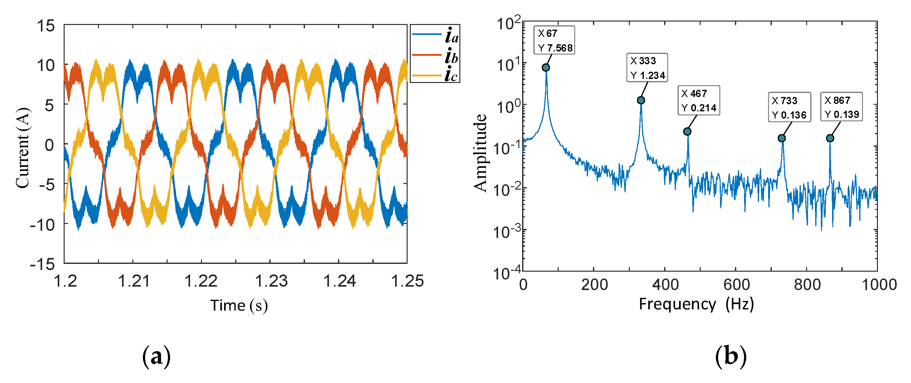
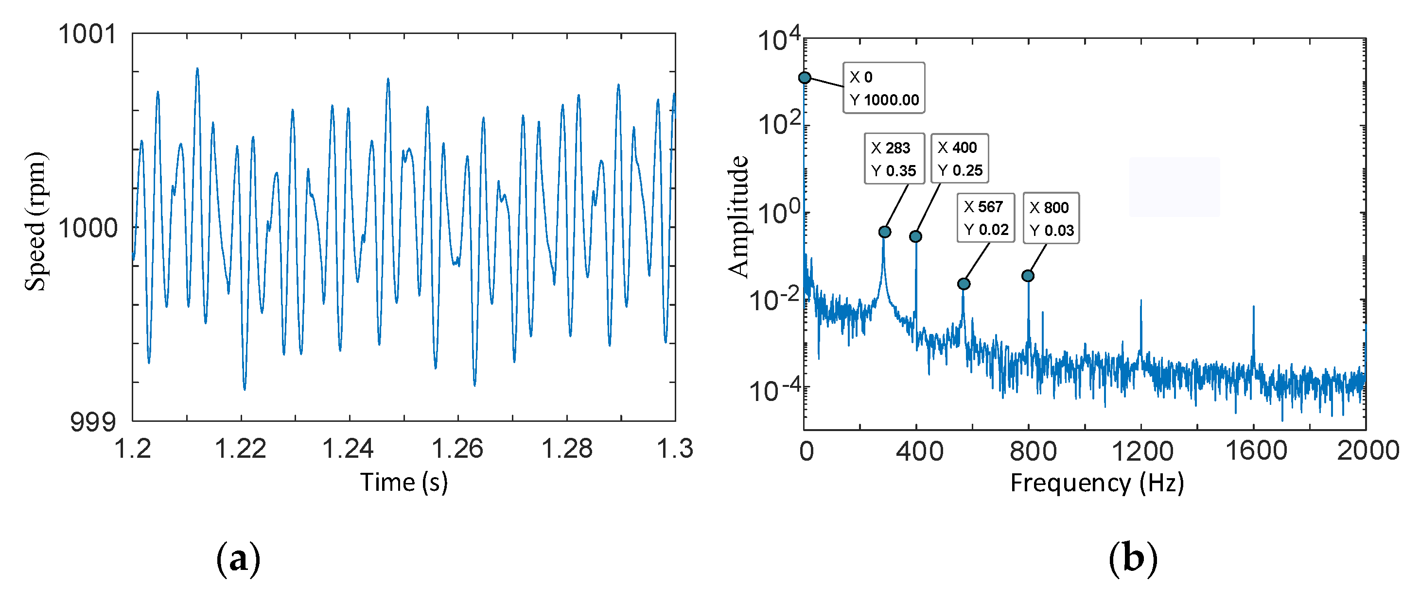
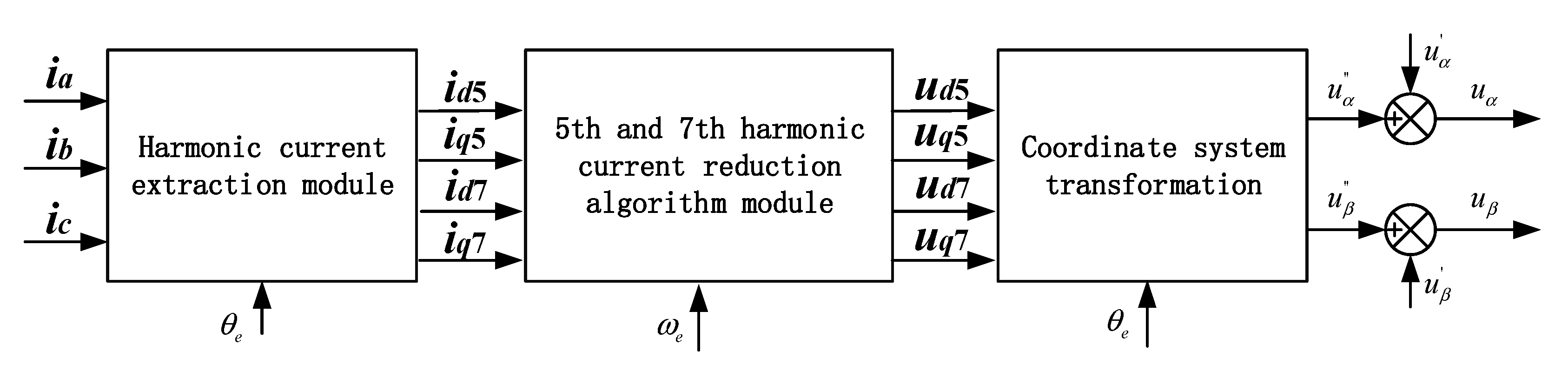
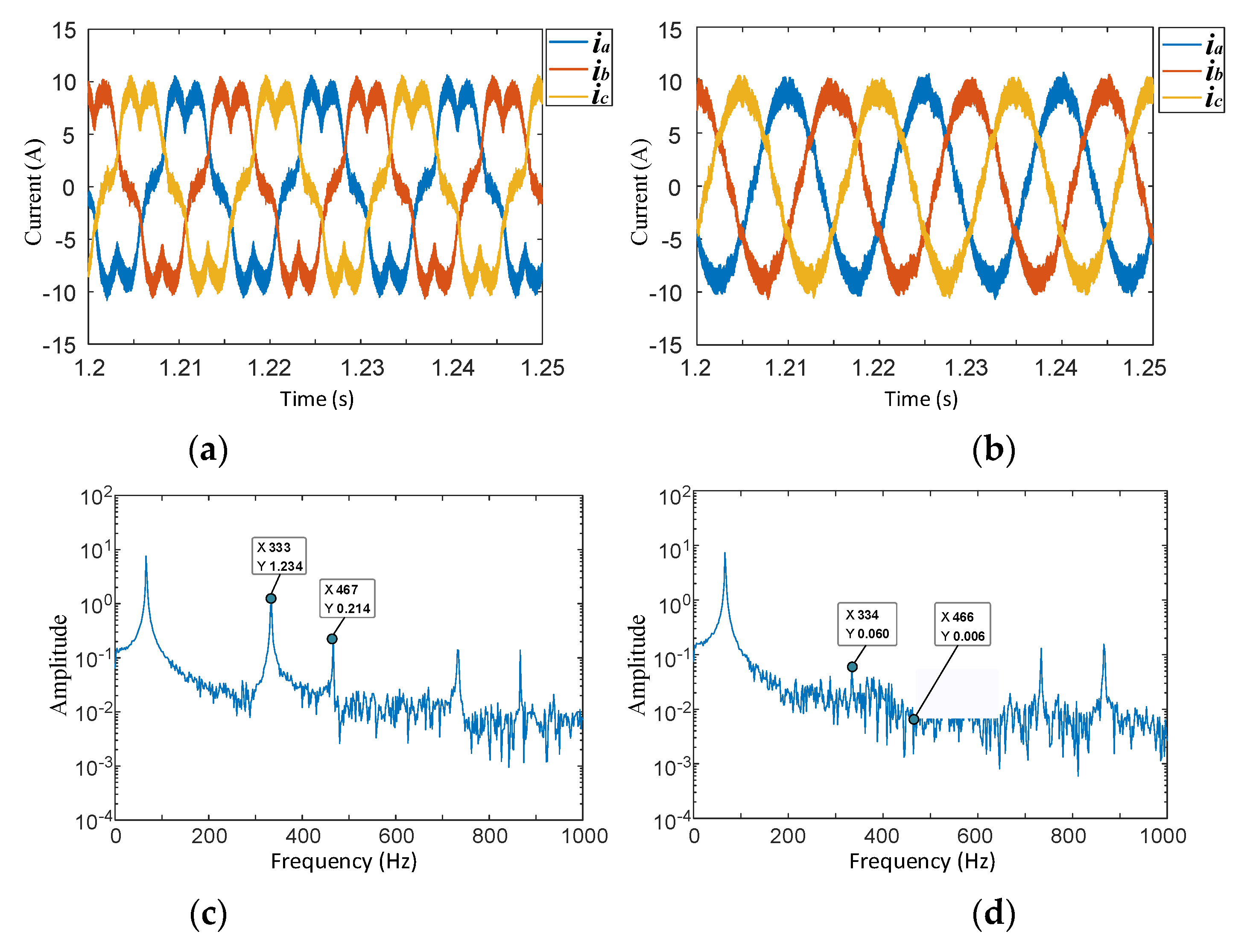
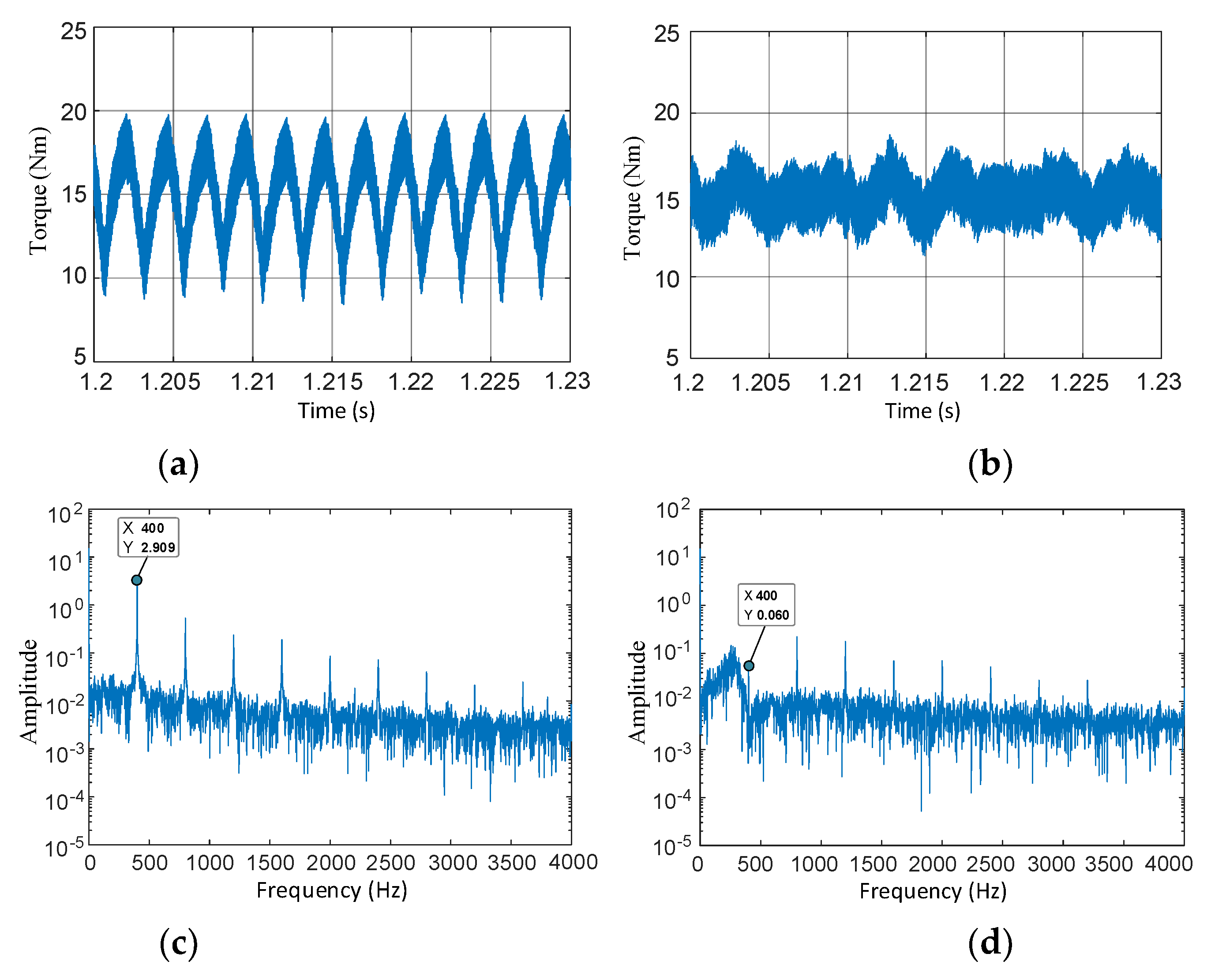
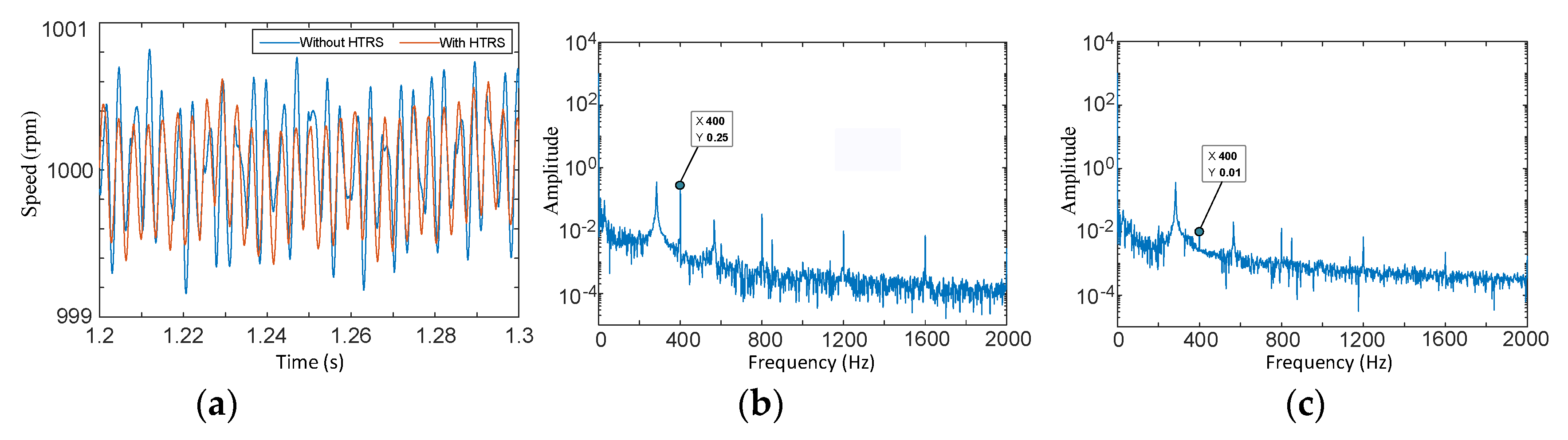
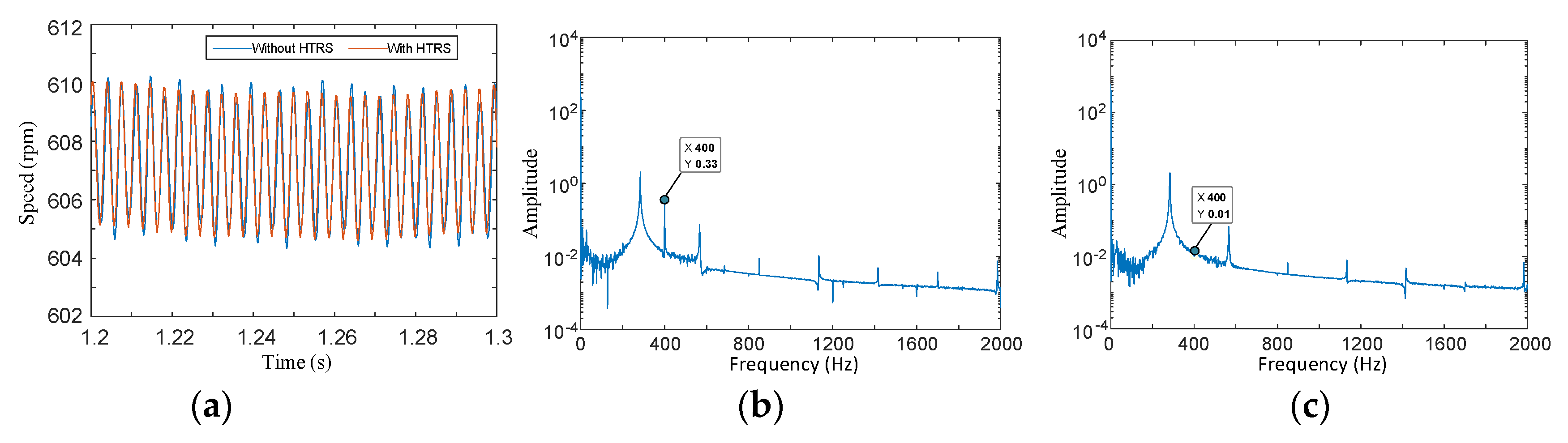
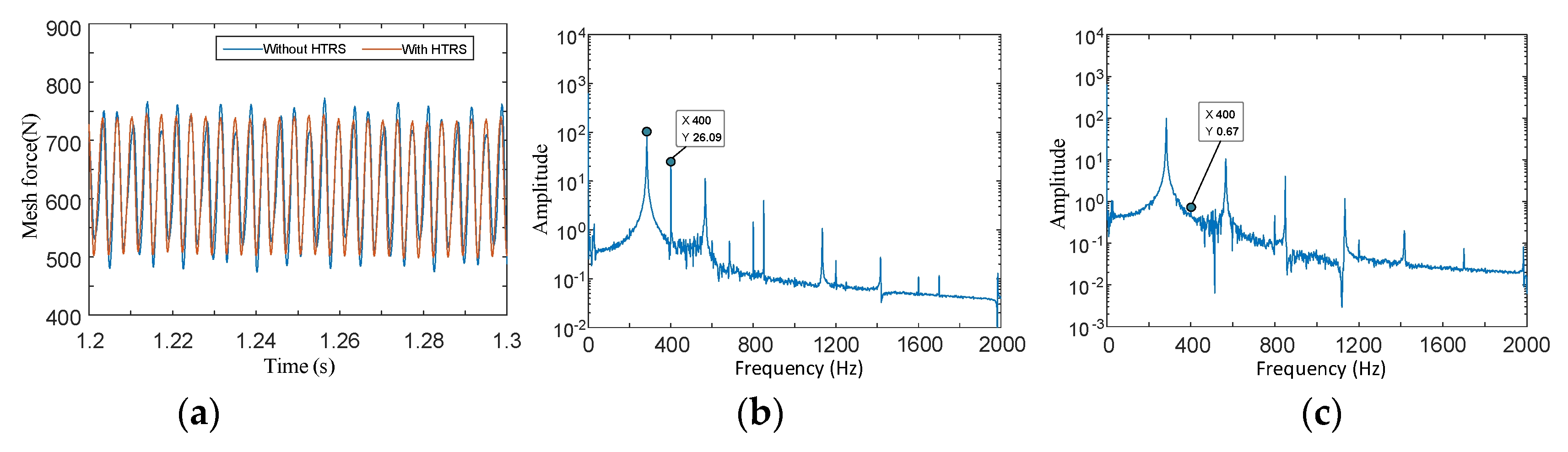
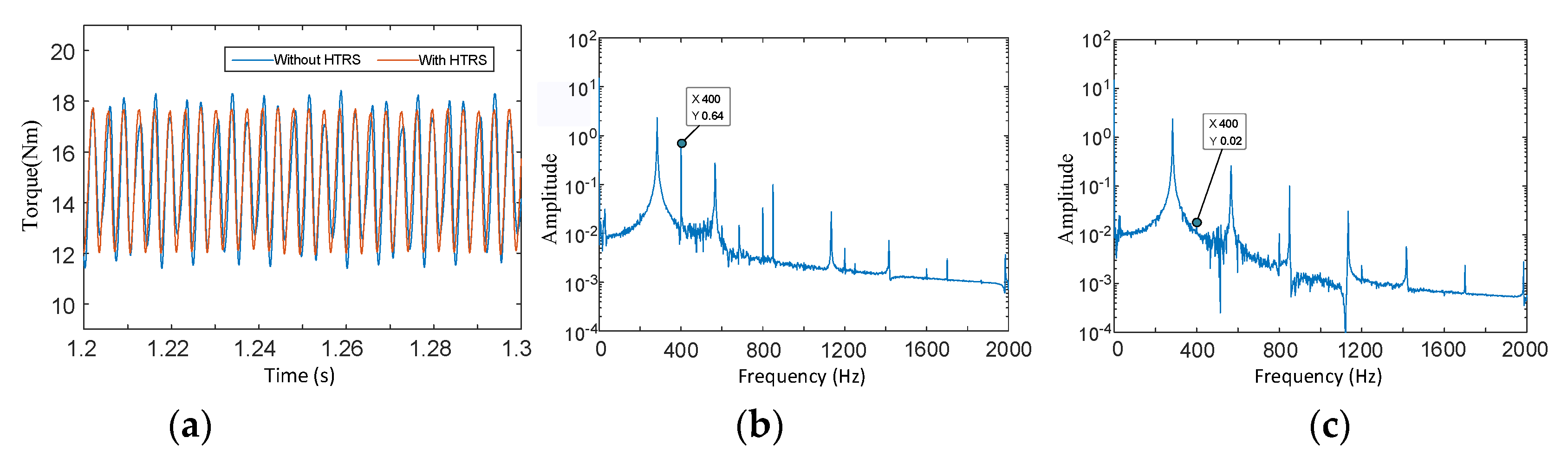
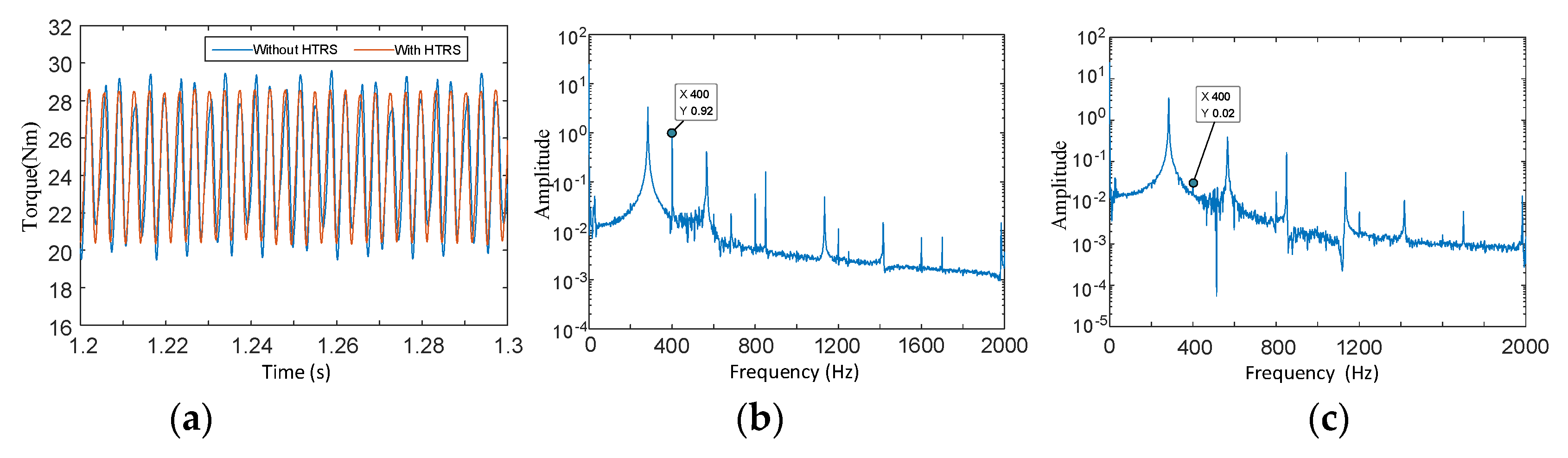
  • By injecting harmonic voltage, a harmonic torque reduction strategy is proposed for an IEDS in this paper. Under the effect of the harmonic torque reduction strategy, the 5th and 7th harmonic currents are effectively reduced, and the total fluctuation amplitude of the electromagnetic torque is reduced by 50%. The simulation results show that the harmonic torque reduction strategy proposed in this paper can effectively reduce the harmonic torque of the IEDS, thus reducing the speed fluctuation and dynamic load of each component of the system and improving the stability of the IEDS.

Author Contributions

Conceptualization, J.H.; Data curation, M.J. and Y.G.; Formal analysis, Y.G.; Funding acquisition, J.H. and S.L.; Investigation, M.J.; Methodology, J.H. and Y.Y.; Project administration, J.H. and C.F.; Resources, S.L.; Software, Y.Y.; Supervision, C.F.; Validation, M.J., Y.G. and C.F.; Visualization, Y.Y.; Writing—original draft, Y.Y.; Writing—review and editing, Y.Y. All authors have read and agreed to the published version of the manuscript.

Funding

This research was funded by the National Key R&D Program of China under Grant No. 2018YFB0106100 and the Chongqing Artificial Intelligence Technology Innovation Major Special Project under Grant No. cstc2018jszx-cyztzx0047.

Conflicts of Interest

The authors declare no conflict of interest.

Appendix A

Table A1. Parameters of the helical gear pair.
ParameterDriving GearDriven GearUnit
Teeth numberZ1 = 17Z2 = 28-
Normal modulus mn33mm
Modulus of end face mt3.193.19mm
Tooth surface width b2323mm
Normal pressure angle αn2020deg
Transverse pressure angle αt21.1721.17deg
Pitch circle helix angle β2020deg
Table A2. Parameters of the transmission system.
ParameterValueUnit
Numerical motor rotor and motor shaft moment of inertia Im0.035kg·m2
Rotational inertia of driving gear of reducer I11.67 × 10−4kg·m2
Rotational inertia of driven gear of reducer I21.2 × 10−3kg·m2
Equivalent moment of inertia of final drive and differential Ig8 × 10−3kg·m2
Wheel moment of inertia Iw0.915kg·m2
Body equivalent moment of inertia IV139.8kg·m2
Torsional stiffness of motor shaft ks18 × 104Nm/rad
Normal meshing stiffness per unit length of gear pair ku6 × 109Nm/mm
Torsional stiffness of output shaft ks22 × 105Nm/rad
Half shaft torsional stiffness ka 8 × 10³Nm/rad
Wheel torsional stiffness kV4.5 × 103Nm/rad
Torsional damping ratio of motor shaft cs1 2Nm∙s/rad
Gear meshing damping cm 800N/(m/s)
Torsional damping ratio of output shaft cs22Nm∙s/rad

Appendix B

C 3 s 5 r = 2 3 [ cos ( 5 θ e ) cos ( 5 θ e 2 3 π ) cos ( 5 θ e 4 3 π ) sin ( 5 θ e ) sin ( 5 θ e 2 3 π ) sin ( 5 θ e 4 3 π ) 1 2 1 2 1 2 ] ;   C 5 r 3 s = 2 3 [ cos ( 5 θ e ) sin ( 5 θ e ) 1 2 cos ( 5 θ e 2 3 π ) sin ( 5 θ e 2 3 π ) 1 2 cos ( 5 θ e 4 3 π ) sin ( 5 θ e 4 3 π ) 1 2 ]
C 3 s 7 r = 2 3 [ cos ( 7 θ e ) cos ( 7 θ e 2 3 π ) cos ( 7 θ e 4 3 π ) sin ( 7 θ e ) sin ( 7 θ e 2 3 π ) sin ( 7 θ e 4 3 π ) 1 2 1 2 1 2 ] ;   C 7 r 3 s = 2 3 [ cos ( 7 θ e ) sin ( 7 θ e ) 1 2 cos ( 7 θ e 2 3 π ) sin ( 7 θ e 2 3 π ) 1 2 cos ( 7 θ e 4 3 π ) sin ( 7 θ e 4 3 π ) 1 2 ]
C 2 r 5 r = [ cos ( 6 θ e ) sin ( 6 θ e ) sin ( 6 θ e ) cos ( 6 θ e ) ] C 5 r 2 r = [ cos ( 6 θ e ) sin ( 6 θ e ) sin ( 6 θ e ) cos ( 6 θ e ) ]
C 2 r 7 r = [ cos ( 6 θ e ) sin ( 6 θ e ) sin ( 6 θ e ) cos ( 6 θ e ) ] C 5 r 2 r = [ cos ( 6 θ e ) sin ( 6 θ e ) sin ( 6 θ e ) cos ( 6 θ e ) ]

References

  1. Wu, Y.C.; Sun, Z.H. Design and Analysis of a Novel Speed-Changing Wheel Hub with an Integrated Electric Motor for Electric Bicycles. Math. Probl. Eng. 2013, 2013, 8. [Google Scholar] [CrossRef]
  2. Burkhardt, Y.; Spagnolo, A.; Lucas, P.; Zavesky, M.; Brockerhoff, P.; IEEE. Design and analysis of a highly integrated 9-phase drivetrain for EV applications. In Proceedings of the 2014 International Conference on Electrical Machines, Berlin, Germany, 2–5 September 2014; pp. 450–456. [Google Scholar]
  3. Zhu, C.; Zeng, Z.; Zhao, R. Torque ripple elimination based on inverter voltage drop compensation for a three-phase four-switch inverter-fed PMSM drive under low speeds. IET Power Electron. 2017, 10, 1430–1437. [Google Scholar] [CrossRef]
  4. Viswanathan, V.; Seenithangom, J. Commutation Torque Ripple Reduction in the BLDC Motor Using Modified SEPIC and Three-Level NPC Inverter. IEEE Trans. Power Electron. 2018, 33, 535–546. [Google Scholar] [CrossRef]
  5. Viswanathan, V.; Jeevananthan, S. Hybrid converter topology for reducing torque ripple of BLDC motor. IET Power Electron. 2017, 10, 1572–1587. [Google Scholar] [CrossRef]
  6. Viswanathan, V.; Jeevananthan, S. Reducing torque ripple of BLDC motor by integrating dc-dc converter with three-level neutral-point-clamped inverter. Compel. Int. J. Comput. Math. Electr. Electron. Eng. 2016, 35, 959–981. [Google Scholar] [CrossRef]
  7. Zeng, Z.; Zhu, C.; Jin, X.; Shi, W.; Zhao, R. Hybrid Space Vector Modulation Strategy for Torque Ripple Minimization in Three-Phase Four-Switch Inverter-Fed PMSM Drives. IEEE Trans. Ind. Electron. 2017, 64, 2122–2134. [Google Scholar] [CrossRef]
  8. Zhu, C.; Zeng, Z.; Zhao, R. Comprehensive Analysis and Reduction of Torque Ripples in Three-Phase Four-Switch Inverter-Fed PMSM Drives Using Space Vector Pulse-Width Modulation. IEEE Trans. Power Electron. 2017, 32, 5411–5424. [Google Scholar] [CrossRef]
  9. Baik, J.; Yun, S.; Kim, D.; Kwon, C.; Yoo, J. Remote-State PWM with Minimum RMS Torque Ripple and Reduced Common-Mode Voltage for Three-Phase VSI-Fed BLAC Motor Drives. Electronics 2020, 9, 586. [Google Scholar] [CrossRef] [Green Version]
  10. Joryo, S.; Tatsumi, K.; Morizane, T.; Taniguchi, K.; Kimura, N.; Omori, H.; IEEE. Study of Torque ripple reduction and Torque boost by Modified Trapezoidal Modulation. In Proceedings of the 2018 International Power Electronics Conference, Niigata, Japan, 20–24 May 2018; pp. 1202–1205. [Google Scholar]
  11. Shimmyo, S.; Takeuchi, K.; Takahashi, N.; Matsushita, M.; Ohnishi, K. Multi-level Motor Drives for Torque Ripple Suppression Taking Control Sensitivity into Account. IEEJ J. Ind. Appl. 2016, 5, 69–77. [Google Scholar] [CrossRef] [Green Version]
  12. Mohan, D.; Zhang, X.; Foo, G.H.B. Three-Level Inverter-Fed Direct Torque Control of IPMSM with Torque and Capacitor Voltage Ripple Reduction. IEEE Trans. Energy Convers. 2016, 31, 1559–1569. [Google Scholar] [CrossRef]
  13. Mohan, D.; Zhang, X.; Foo, G.H.B. A Simple Duty Cycle Control Strategy to Reduce Torque Ripples and Improve Low-Speed Performance of a Three-Level Inverter Fed DTC IPMSM Drive. IEEE Trans. Ind. Electron. 2017, 64, 2709–2721. [Google Scholar] [CrossRef]
  14. Wang, X.; Zhou, Y.; Yang, D.; Shi, X.; IEEE. Direct Torque Control of Three-Level Inverter-Fed PMSM Based on Zero Voltage Vector Distribution for Torque Ripple Reduction. In Proceedings of the 2017 29th Chinese Control and Decision Conference, Chongqing, China, 28–30 May 2017; pp. 7776–7781. [Google Scholar]
  15. Mohan, D.; Zhang, X.N.; Foo, G.H.B. Three-Level Inverter-Fed Direct Torque Control of IPMSM With Constant Switching Frequency and Torque Ripple Reduction. IEEE Trans. Ind. Electron. 2016, 63, 7908–7918. [Google Scholar] [CrossRef]
  16. Mohan, D.; Zhang, X.N.; Foo, G.H.B. Generalized DTC Strategy for Multilevel Inverter Fed IPMSMs With Constant Inverter Switching Frequency and Reduced Torque Ripples. IEEE Trans. Energy Convers. 2017, 32, 1031–1041. [Google Scholar] [CrossRef]
  17. Tatte, Y.N.; Aware, M.V. Torque Ripple and Harmonic Current Reduction in a Three-Level Inverter-Fed Direct-Torque-Controlled Five-Phase Induction Motor. IEEE Trans. Ind. Electron. 2017, 64, 5265–5275. [Google Scholar] [CrossRef]
  18. Dhiman, S.; Hussain, A.; Kumar, V.T. An Effective Voltage Switching State Algorithm for Direct Torque Controlled Five-Phase Induction Motor Drive to Reduce Torque Ripple. In Proceedings of the 2016 IEEE Students’ Conference on Electrical, Electronics and Computer Science, Bhopal, India, 5–6 March 2016. [Google Scholar]
  19. Zhang, G.Z.; Chen, C.; Gu, X.; Wang, Z.A.; Li, X.M. An Improved Model Predictive Torque Control for a Two-Level Inverter Fed Interior Permanent Magnet Synchronous Motor. Electronics 2019, 8, 769. [Google Scholar] [CrossRef] [Green Version]
  20. Dong, Y.; Nuchkrua, T.; Shen, T. Asymptotical stability contouring control of dual-arm robot with holonomic constraints: Modified distributed control framework. IET Control Theory Appl. 2019, 13, 2877–2885. [Google Scholar] [CrossRef]
  21. Li, K.L.; Boonto, S.; Nuchkrua, T. On-line Self Tuning of Contouring Control for High Accuracy Robot Manipulators under Various Operations. Int. J. Control Autom. Syst. 2020, 18, 1818–1828. [Google Scholar] [CrossRef]
  22. Lu, J.; Yang, J.G.; Ma, Y.C.; IEEE. Research on Harmonic Compensation for Flux and Current of Permanent Magnet Synchronous Motor. In Proceedings of the 2015 IEEE International Conference on Advanced Intelligent Mechatronics, Busan, Korea, 7–11 July 2015; pp. 589–594. [Google Scholar]
  23. Boroujeni, M.S.; Markadeh, G.R.A.; Soltani, J. Torque ripple reduction of brushless DC motor based on adaptive input-output feedback linearization. ISA Trans. 2017, 70, 502–511. [Google Scholar] [CrossRef]
  24. Boroujeni, M.S.; Markadeh, G.A.; Soltani, J.; IEEE. Adaptive Input-Output Feedback Linearization Control of Brushless DC Motor with Arbitrary Current Reference using Voltage Source Inverter. In Proceedings of the 2017 8th Power Electronics, Drive Systems & Technologies Conference, Mashhad, Iran, 14–16 February 2017; pp. 537–542. [Google Scholar]
  25. Jedryczka, C.; Danielczyk, D.; Szelag, W. Torque Ripple Minimization of the Permanent Magnet Synchronous Machine by Modulation of the Phase Currents. Sensors 2020, 20, 2406. [Google Scholar] [CrossRef] [Green Version]
  26. Boroujeni, M.S.; Markadeh, G.A.; Soltani, J.; Blaabjerg, F. Torque ripple reduction of brushless DC motor with harmonic current injection based on integral terminal sliding mode control. IET Electr. Power Appl. 2018, 12, 25–36. [Google Scholar] [CrossRef]
  27. Li, Z.; Peng, Z. Nonlinear dynamic response of a multi-degree of freedom gear system dynamic model coupled with tooth surface characters: A case study on coal cutters. Nonlinear Dyn. 2016, 84, 271–286. [Google Scholar] [CrossRef]
  28. Chen, Z.G.; Zhai, W.M.; Wang, K.Y. Vibration feature evolution of locomotive with tooth root crack propagation of gear transmission system. Mech. Syst. Signal Process. 2019, 115, 29–44. [Google Scholar] [CrossRef]
  29. Ding, H.L.; Kahraman, A. Interactions between nonlinear spur gear dynamics and surface wear. J. Sound Vibr. 2007, 307, 662–679. [Google Scholar] [CrossRef]
  30. Cai, Z.; Lin, C. Dynamic Model and Analysis of Nonlinear Vibration Characteristic of a Curve-Face Gear Drive. Stroj. Vestn. J. Mech. Eng. 2017, 63, 161–170. [Google Scholar] [CrossRef]
  31. Lin, C.; Liu, Y.; Gu, S.J. Analysis of nonlinear twisting vibration characteristics of orthogonal curve-face gear drive. J. Braz. Soc. Mech. Sci. Eng. 2015, 37, 1499–1505. [Google Scholar] [CrossRef]
  32. Parker, R.C.; Ambarisha, V.K.; Asme. Nonlinear dynamics of planetary gears using analytical and finite element models. J. Sound Vib. 2008, 302, 577–595. [Google Scholar]
  33. Liu, C.Z.; Qin, D.T.; Wei, J.; Liao, Y.H. Investigation of nonlinear characteristics of the motor-gear transmission system by trajectory-based stability preserving dimension reduction methodology. Nonlinear Dyn. 2018, 94, 1835–1850. [Google Scholar] [CrossRef]
  34. Bai, W.; Qin, D.; Wang, Y.; Lim, T.C. Dynamic characteristics of motor-gear system under load saltations and voltage transients. Mech. Syst. Signal Process. 2018, 100, 1–16. [Google Scholar] [CrossRef]
  35. Bai, W.; Qin, D.; Wang, Y.; Lim, T.C. Dynamic characteristic of electromechanical coupling effects in motor-gear system. J. Sound Vib. 2018, 423, 50–64. [Google Scholar] [CrossRef]
  36. Wang, Z.W.; Mei, G.M.; Xiong, Q.; Yin, Z.H.; Zhang, W.H. Motor car-track spatial coupled dynamics model of a high-speed train with traction transmission systems. Mech. Mach. Theory 2019, 137, 386–403. [Google Scholar] [CrossRef]
  37. Wei, J.T.; Kang, J.S.; Cui, Y.H. Analysis and Inhibition of Permanent Magnet Synchronous Motor Torque Ripple. Mechatronics 2014, 12, 15–19. [Google Scholar] [CrossRef]
  38. Liao, Y.; Zhen, S.; Liu, R.; Yao, J. Torque Ripple Suppression of Permanent Magnet Synchronous Motor by the Harmonic Injection. In Proceedings of the 2018 Asia-Pacific Magnetic Recording Conference, Shanghai, China, 15–17 November 2011; Volume 21, pp. 121–129. [Google Scholar]
Figure 1. General structure diagram of an integrated electric drive system.
Electronics 09 01241 g001
Figure 2. Structure diagram of a pure electric vehicle (PEV) power transmission system equipped with an integrated electric drive system (IEDS).
Electronics 09 01241 g002
Figure 3. Inverter circuit of the PMSM.
Electronics 09 01241 g003
Figure 4. Structure diagram of the A-phase bridge arm of the inverter.
Electronics 09 01241 g004
Figure 5. Voltage waveform of the A-phase bridge arm.
Electronics 09 01241 g005
Figure 6. Error voltage waveform generated by inverter nonlinear characteristics.
Electronics 09 01241 g006
Figure 7. Time-varying meshing stiffness of gear pair.
Electronics 09 01241 g007
Figure 8. 6-DOF torsional vibration model of a power transmission system.
Electronics 09 01241 g008
Figure 9. Electromechanical coupling dynamic model of a PEV.
Electronics 09 01241 g009
Figure 10. Electromagnetic torque of PMSM in an IEDS: (a) Electromagnetic torque in time domain; (b) Frequency spectrum of electromagnetic torque.
Electronics 09 01241 g010
Figure 11. Three-phase current of PMSM in an IEDS: (a) Three-phase current in time domain; (b) Frequency spectrum of A phase current.
Electronics 09 01241 g011
Figure 12. Shaft speed of the PMSM in the IEDS: (a) Shaft speed in time domain; (b) Frequency spectrum of shaft speed.
Electronics 09 01241 g012
Figure 13. Gear pair speed of reducer in the IEDS: (a) Driving gear speed in time domain; (b) Frequency spectrum of driving gear speed; (c) Driven gear speed in time domain; (d) Frequency spectrum of driven gear speed.
Electronics 09 01241 g013
Figure 14. Gear pair meshing force of the reducer in the IEDS: (a) Meshing force in the time domain; (b) Frequency spectrum of the meshing force.
Electronics 09 01241 g014
Figure 15. Gear pair meshing displacement of the reducer in the IEDS: (a) Meshing displacement in the time domain; (b) Frequency spectrum of the meshing displacement.
Electronics 09 01241 g015
Figure 16. Dynamic transfer torque of the motor shaft in the IEDS: (a) Dynamic transfer torque in the time domain; (b) Frequency spectrum of dynamic transfer torque.
Electronics 09 01241 g016
Figure 17. Dynamic transfer torque of the output shaft in the IEDS: (a) Dynamic transfer torque in the time domain; (b) Frequency spectrum of the dynamic transfer torque.
Electronics 09 01241 g017
Figure 18. Separation strategy of 5th and 7th harmonic currents of a PMSM.
Electronics 09 01241 g018
Figure 19. 5th and 7th synchronous rotation coordinate systems of a motor.
Electronics 09 01241 g019
Figure 20. Control block diagram of motor harmonic current decoupling: (a) 5th harmonic current; (b) 7th harmonic current.
Electronics 09 01241 g020
Figure 21. Harmonic torque reduction control strategy.
Electronics 09 01241 g021
Figure 22. Electromechanical coupling dynamic model of a PEV considering harmonic torque.
Electronics 09 01241 g022
Figure 23. Three-phase current of a PMSM in an IEDS: (a) Three-phase current of the stator in the time domain before adding the harmonic reduction strategy; (b) Three-phase current of the stator in the time domain after adding the harmonic reduction strategy; (c) Frequency spectrum of the A-phase current before adding the harmonic reduction strategy; (d) Frequency spectrum of the A-phase current after adding the harmonic reduction strategy.
Electronics 09 01241 g023
Figure 24. Electromagnetic torque of a PMSM in an IEDS: (a) Electromagnetic torque in the time domain before adding the harmonic reduction strategy; (b) Electromagnetic torque in the time domain after adding the harmonic reduction strategy; (c) Frequency spectrum of electromagnetic torque before adding the harmonic reduction strategy; (d) Frequency spectrum of electromagnetic torque after adding the harmonic reduction strategy.
Electronics 09 01241 g024
Figure 25. Shaft speed of a PMSM in an IEDS: (a) Shaft speed in the time domain; (b) Frequency spectrum of the shaft speed before adding the harmonic reduction strategy; (c) Frequency spectrum of the shaft speed after adding the harmonic reduction strategy.
Electronics 09 01241 g025
Figure 26. Driving gear speed of the reducer in an IEDS: (a) Driving gear speed in the time domain; (b) Frequency spectrum of the driving gear speed before adding the harmonic reduction strategy; (c) Frequency spectrum of the driving gear speed after adding the harmonic reduction strategy.
Electronics 09 01241 g026
Figure 27. Driven gear speed of the reducer in an IEDS: (a) Driven gear speed in the time domain; (b) Frequency spectrum of the driven gear speed before adding the harmonic reduction strategy; (c) Frequency spectrum of the driven gear speed after adding the harmonic reduction strategy.
Electronics 09 01241 g027
Figure 28. Driven meshing force of the reducer gear pair in an IEDS: (a) Reducer gear pair meshing force in the time domain; (b) Frequency spectrum of the meshing force before adding the harmonic reduction strategy; (c) Frequency spectrum of the meshing force after adding the harmonic reduction strategy.
Electronics 09 01241 g028
Figure 29. Dynamic torque of the motor shaft in an IEDS: (a) Motor shaft dynamic torque in the time domain; (b) Frequency spectrum of dynamic torque before adding the harmonic reduction strategy; (c) Frequency spectrum of dynamic torque after adding the harmonic reduction strategy.
Electronics 09 01241 g029
Figure 30. Dynamic torque of the output shaft in an IEDS: (a) Output shaft dynamic torque in the time domain; (b) Frequency spectrum of dynamic torque before adding the harmonic reduction strategy; (c) Frequency spectrum of dynamic torque after adding the harmonic reduction strategy.
Electronics 09 01241 g030
Table 1. Parameters of the permanent magnet synchronous motor (PMSM) in this paper.
ParameterValueUnit
Peak power60kW
Peak torque250Nm
Maximum speed7000rpm
Base speed2292rpm
DC voltage650V
Stator resistance0.153Ω
Stator inductance1.8mH
Permanent magnet flux linkage ψ f 0.2778Wb
Pole number Pn4-
Phase current limit150A
Table 2. Parameters of the inverter in this paper. IGBT: insulated gate bipolar transistor.
ParameterValveUnit
DC bus voltage udc650V
Modulation carrier period TPWM100μs
IGBT turn on time ton1μs
Voltage drop of IGBT switch tube ut3V
Modulation carrier frequency fPWM10kHz
Dead time td4μs
IGBT turn off time toff2μs
Conduction voltage drop of freewheeling diode ud2V
Table 3. Data comparison of the IEDS before and after adding the harmonic torque reduction strategy.
ParameterBefore Adding Harmonic Torque Reduction StrategyAfter Adding Harmonic Torque Reduction StrategyOptimization Effect (%)
5th harmonic current amplitude (A)1.2340.0695.1
7th harmonic current amplitude (A)0.2140.00697.2
6th harmonic torque (Nm)2.9090.0697.9
Overall fluctuation amplitude of motor torque (Nm)10550.0
Fluctuation amplitude of motor shaft speed (rpm)0.250.0196.0
Amplitude of driving gear speed fluctuation caused by 6th harmonic torque (rpm)0.440.0197.7
Fluctuation amplitude of driven gear speed caused by 6th harmonic torque (rpm)0.330.0197.0
Amplitude of meshing force fluctuation of gear pair caused by 6th harmonic torque (N)26.090.6797.4
Amplitude of shaft dynamic load fluctuation caused by 6th harmonic torque (Nm)0.640.0296.9
Amplitude of output shaft dynamic load fluctuation caused by 6th harmonic torque (Nm)0.920.0297.8

