1. Introduction
Steel manufacturing is a highly power-intensive process, wherein about 8% of the total energy consumption is absorbed in hot steel rolling. During the beginning stage of the rough rolling mill, steel slabs from the continuous casting stage are rolled to produce products like plates or strips. Subsequent stages use the above intermediate products for production of thin sheets and similar items. In order to eliminate oxide layers, the hot steel slab specimen has to undergo surface cleaning by means of scrubbing. With the deployment of high-powered electric motors using a gear train arrangement, the set of work and backup rolls are initiated. The physical parameters of the material, like the dimensions of the roller, the work temperature, and the metallurgical properties, are considered during the rolling process, while the torque and rolling force need to be calculated during the multi-pass operation. Profiles involving forward–reverse rolling based on the above calculations facilitate fixing the speed of the shaft and the torque that constitute the operating points of the motor that is driving.
The choice of electric motors includes induction-based motors, synchronous motors, and direct current (DC) motors. Among the various motors, a specially designed motor called the Brushless direct current motor is preferred, based on inherent features like low maintenance, owing to the absence of brushes, no sparking, and less wear and tear.
The modeling of the closed loop drive system, along with a controller using speed and current feedback, integrated with equations governing the steel rolling process, is presented in this paper. A Simulink [
1] schematic of the drive system was created to meet the requirements of the work profile. The performance characteristics of the drive motor were ascertained for ten passes of steel rolling. The characteristics involving the back EMF (electromotive force), such as the current of the stator, the speed of the shaft, and the electromagnetic torque are clearly manifested in this paper by means of simulation.
2. Model of a Rolling Mill
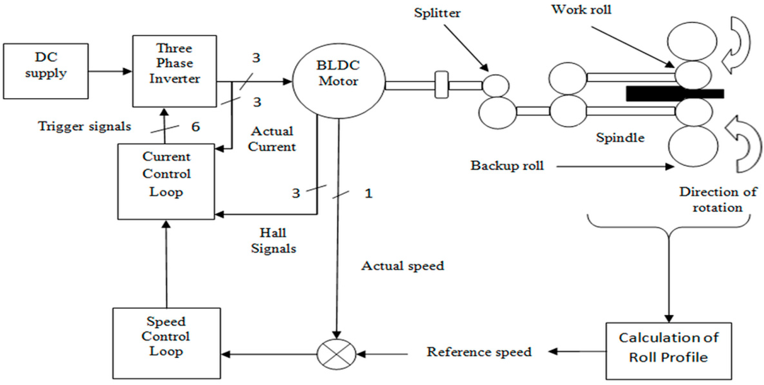
Figure 1 shows a simplified schematic of a typical rough rolling mill for handling hot steel slabs for thickness reduction. The Brushless Direct Current (BLDC) motor [
2] drive operates the system of backup rolls, the pair of work rolls, and a gear train [
3] mechanism. The above drive system is made up of a four-pole BLDC motor [
4] and a six-pulse inverter fed from a DC source. The control configuration senses the speed error signal, which is processed through a Proportional plus Integral controller to generate reference torque. The actual stator current is compared with the generated reference current for producing logic and timing signals required for gate control of the six-pulse IGBT inverter.
2.1. Formulae Governing the Hot Rolling Process
The deformation due to the rolling of a hot slab of steel (which is known by the term draft D) leading to the reduction of thickness of the material [
5,
6], under specified operating conditions, is governed by the following equation:
where D = draft in mm;
= starting thickness in mm; and
= final thickness in mm.
The work piece under consideration is rolled based on thickness, with
being the true strain whose equation, before and after the rolling of the work material, is given by
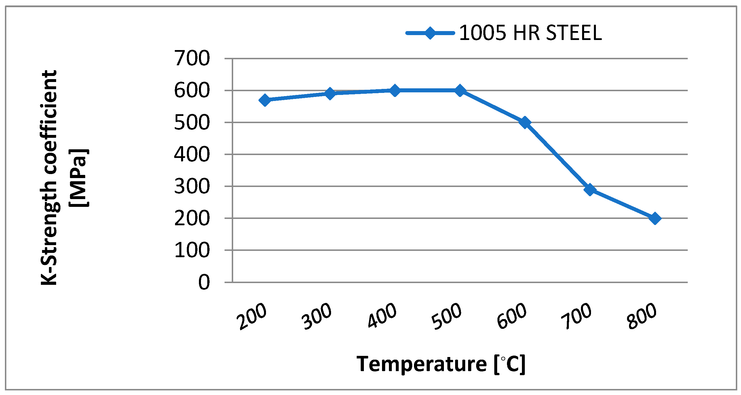
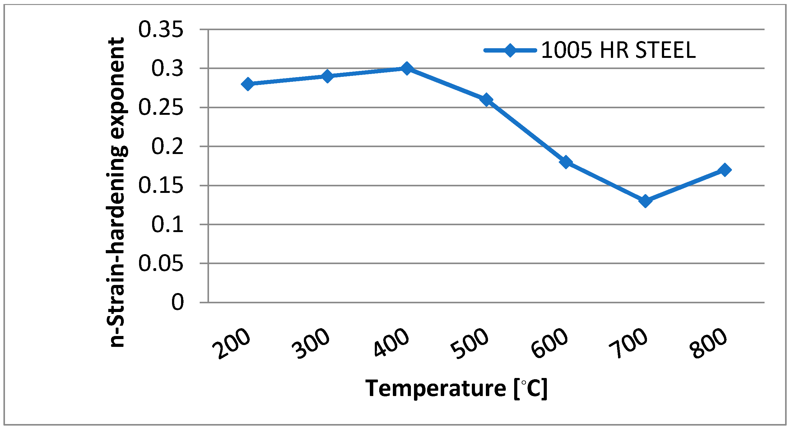
The following equation is used to compute the average flow stress (
)on the work material during flat rolling, where
is the strength coefficient of the material in MPa, and
is the strain-hardening exponent obtained as in
Figure 2 and
Figure 3 for 1005 Hot Rolled steel material:
The contact length (
) is given by
where
= Radius of the work roll in mm.
Rolling force (F) is given by
where w = steel slab width in mm.
Load torque (
) is given by which is related to force as follows:
2.2. Rolling Process Parameters
For the low carbon specimen of 1005 HR steel [
7,
8], the metallurgical data and parameters [
9] were obtained from the standard ASM Metals Handbook and shown in
Table 1.
Figure 2 shows the variation of the strength coefficient (K) and
Figure 3 the strain hardening coefficient (n) with respect to temperature in °C.
The actual rolling of the steel slab [
10] was carried out in a forward–reverse manner, cyclically, over 10 passes with successive thickness reductions and increases in roll speed, as shown in
Table 2.
3. Creation of Speed and Torque Values
The speed and torque values were deduced from the equations formed from the hot rolling process by employing various values from the graphs of the strength coefficient versus temperature, and the strain hardening exponent versus temperature. It is desirable for the thickness reduction to be performed at a higher speed, provided that the operation is quick and utmost care is taken, as a slight reduction in temperature causes hardening of the hot specimen. Hence, several passes are suggested for rolling operations and the direction of rotation of the work roll reverses at the end of the work specimen, which also makes the steel slab move in the reverse direction. This action is repeated several times to realize multiple-roll operation. Alternate positive and negative values were acquired from both the torque and drive speed, corresponding to the 1st and 3rd quadrant operation of the BLDC motor [
11,
12,
13].
Table 3 indicates the values of roller speed, motor speed, shaft torque, and thickness reduction for the total time duration of 50 s.
4. Feedback Controller Design
The profile values from
Table 3 are the specific values of torque and speed for the steel rolling operation of the mill. The BLDC drive should confine its operation to the required stator current and inverter frequency. This was effected by means of a suitable controller, and a suitable inner and outer control loop. A PI controller was used in the loops. Speed error was processed in the outer loop of the controller, which produced a reference for the torque, in order to generate the three phase currents that were used as a further reference in the control mechanism as follows:
The actual values of the phase currents belonging to the motor were compared with the above generated reference currents, involving a bang-bang control for limiting the signal within the hysteresis band, for further generation of six gating pulses for the three-phase inverter [
2]. The first and third quadrant operation of the brushless DC motor, for both forward and reverse operation was governed by profile values of speed and torque, with polarity reversal in the rolling operation. Suitable parameters for the controller were chosen for the smooth operation of the entire system.
5. Schematic of the Modeled System
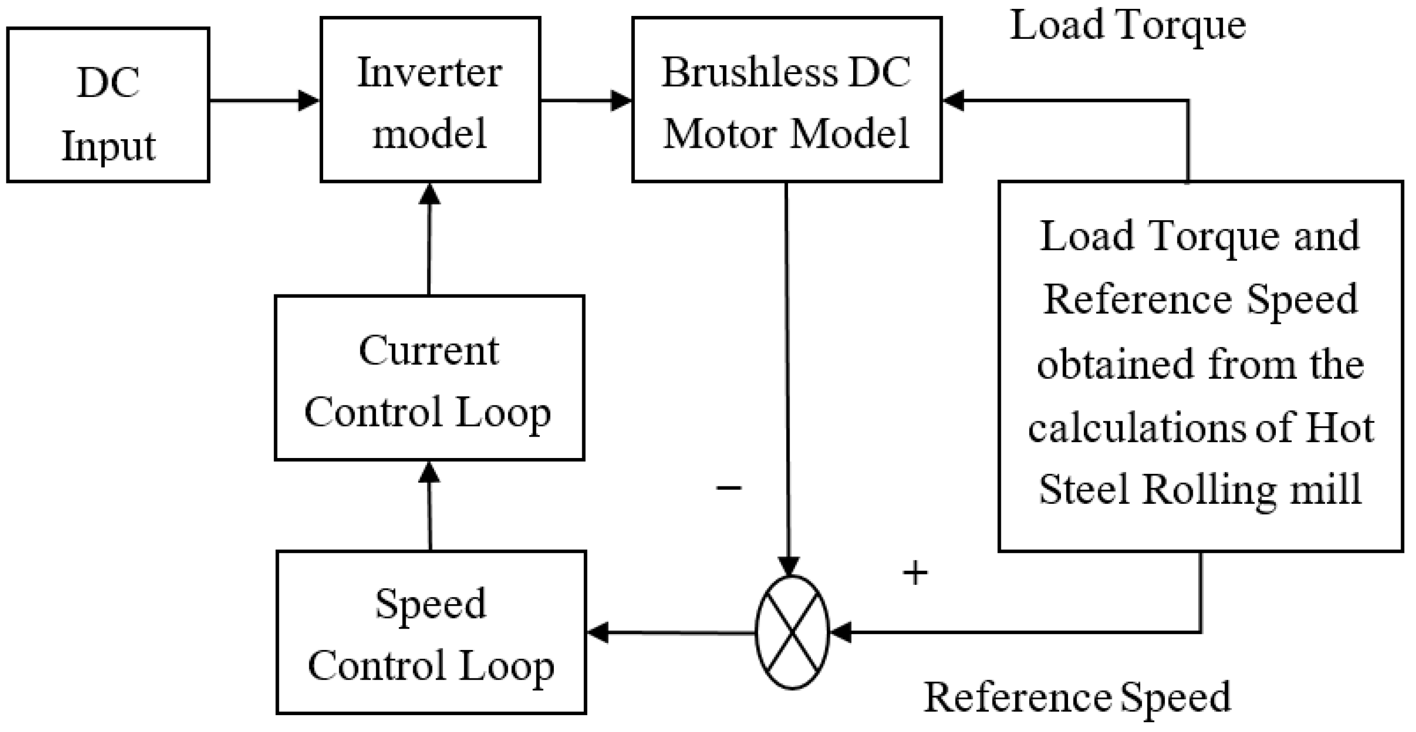
The MATLAB/Simulink simulation platform was employed to carry out the modeling of the hot roughing steel rolling mill, as depicted in
Figure 4. Along with the various parameters of the process model, torque–speed profile values at the motor shaft over ten passes, as shown in
Table 3, were specified. These profile data [
14,
15,
16] correspond to the operating conditions during multi-cyclic, forward–reverse runs of rolling being carried out [
17,
18].
Simulation Results
A simulation run was captured for a period of 50 s, portraying the stator current, back EMF, electromagnetic torque, and speed of the rotor.
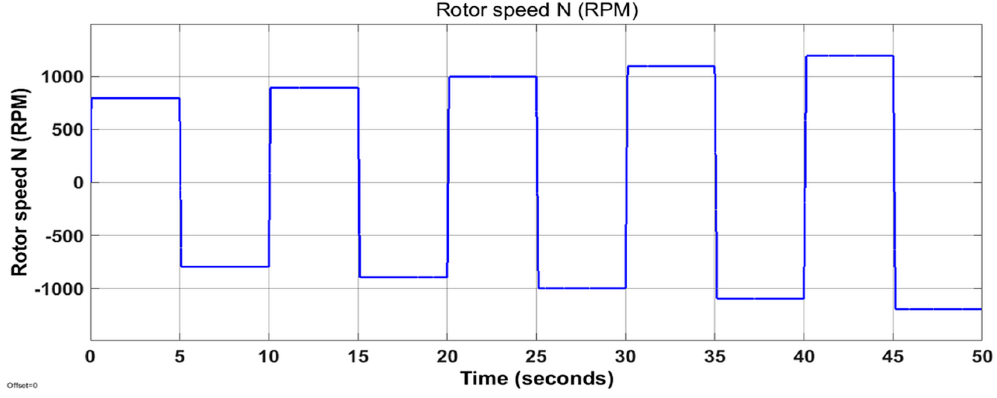
Figure 5 shows the simulation results of the rolling operation over an entire period of 50 s for ten passes, depicting the first and third quadrant operation of the BLDC drive system following the speed profile.
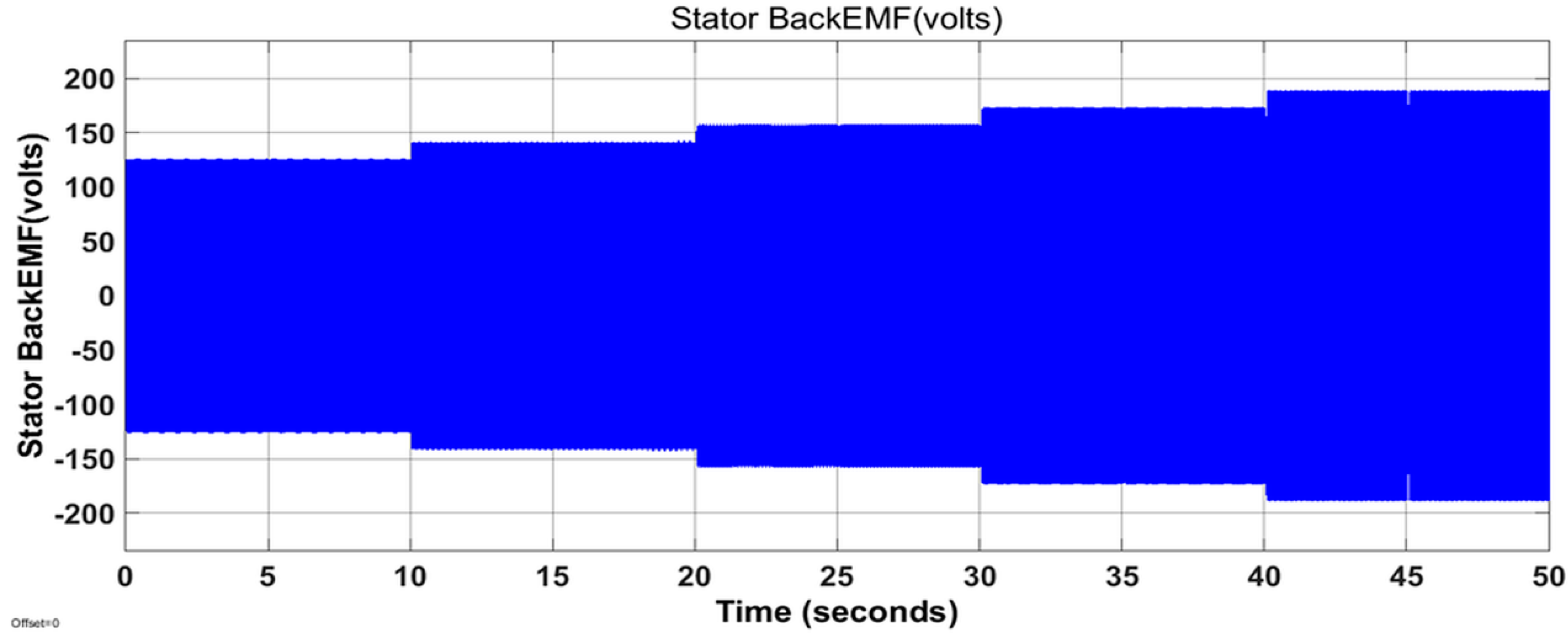
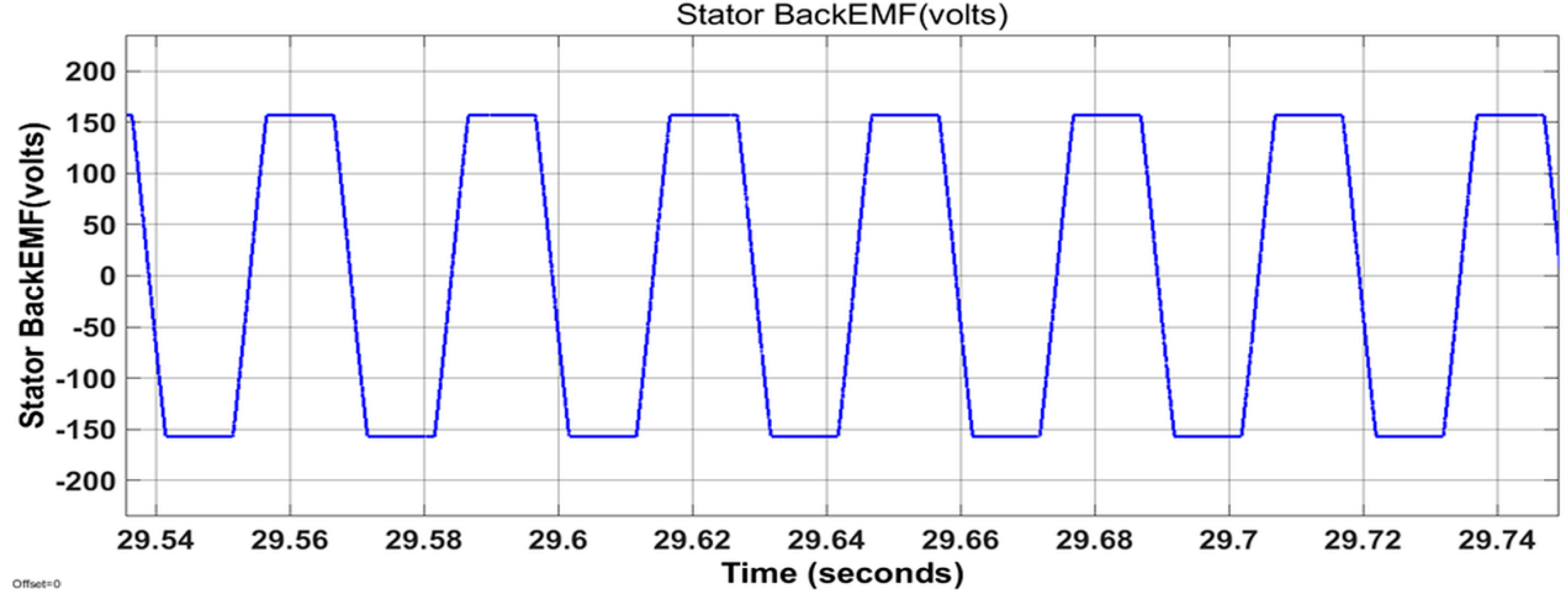
In
Figure 6, the back-EMF waveform is shown for 50 s over ten passes, depicting the first and third quadrant operation of the BLDC drive system. Its expanded view, which is trapezoidal, is shown over a particular period in
Figure 7.
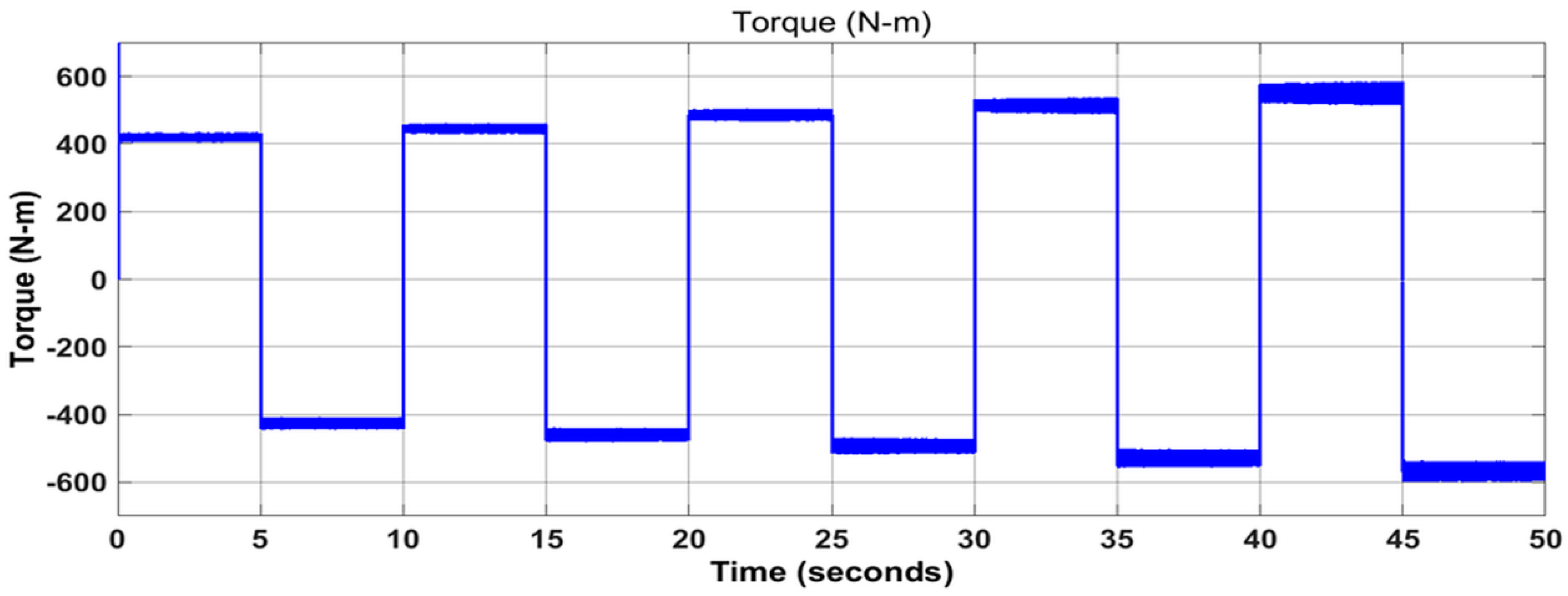
The waveform shown in
Figure 8 depicts the simulated output of the electromagnetic torque over an entire period of 50 s and for the ten passes required for the first and third quadrant operation of the BLDC drive system [
19,
20] following the torque profile.
The efficacious nature of the controller is clearly demonstrated in the rapid reversal involved, with respect to the torque and speed characteristics, needed during the rolling process, as shown in
Figure 5 and
Figure 8. As the rolling process progresses, the quick response of the drive system for bidirectional rolling clearly presents a series of stepped increases of all variables over successive periods.
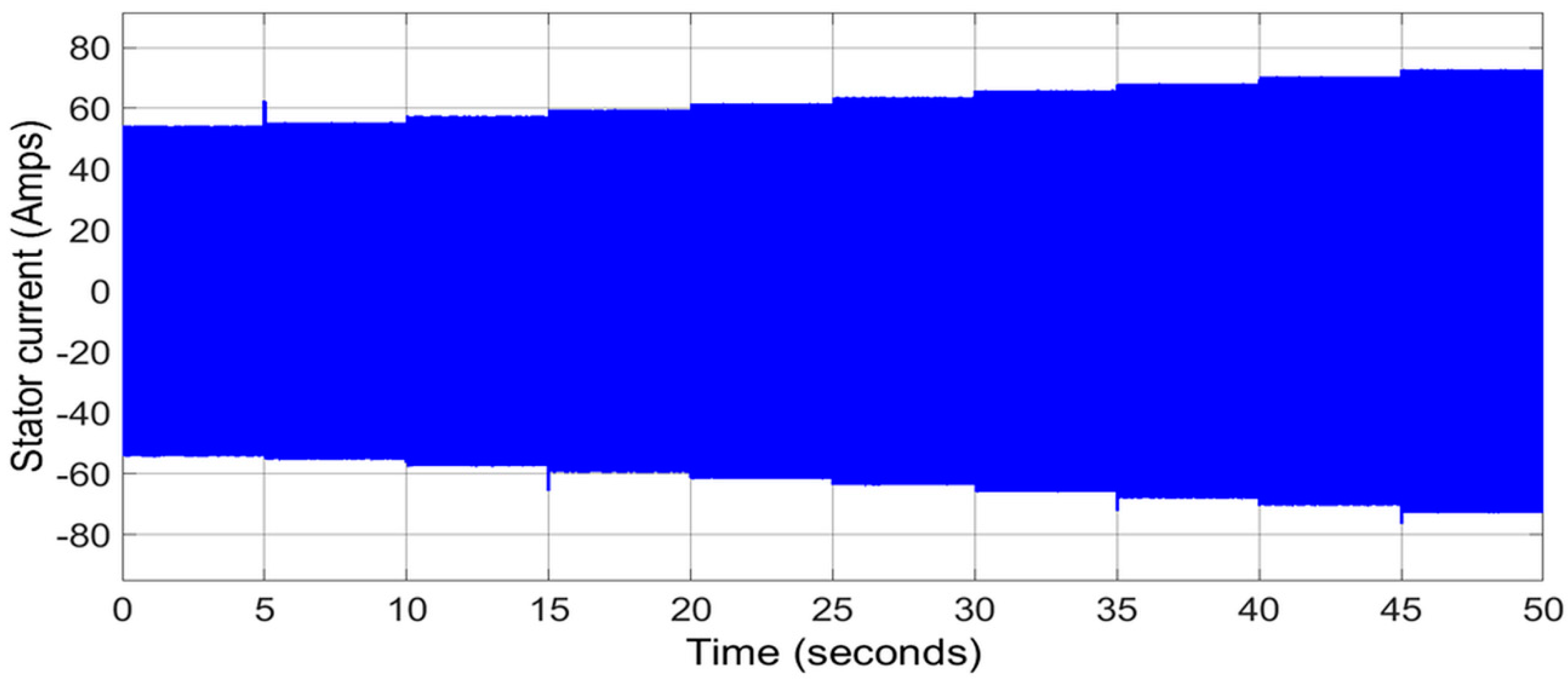
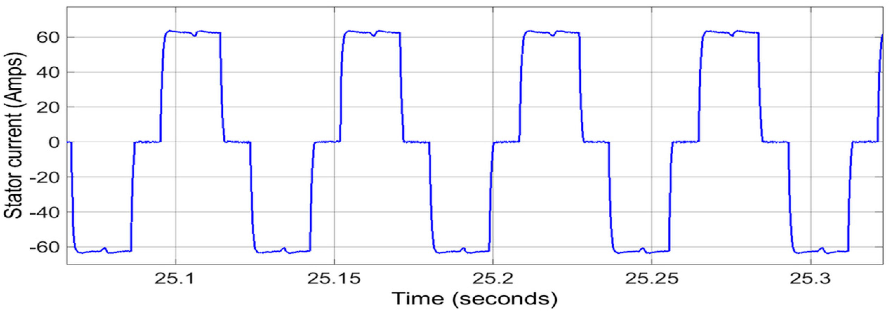
The stator current waveform, shown in
Figure 9, depicts the simulation results for an entire period of 50 s, over ten passes, and its expanded view is also shown in
Figure 10, over a particular period, which is rectangular in shape.
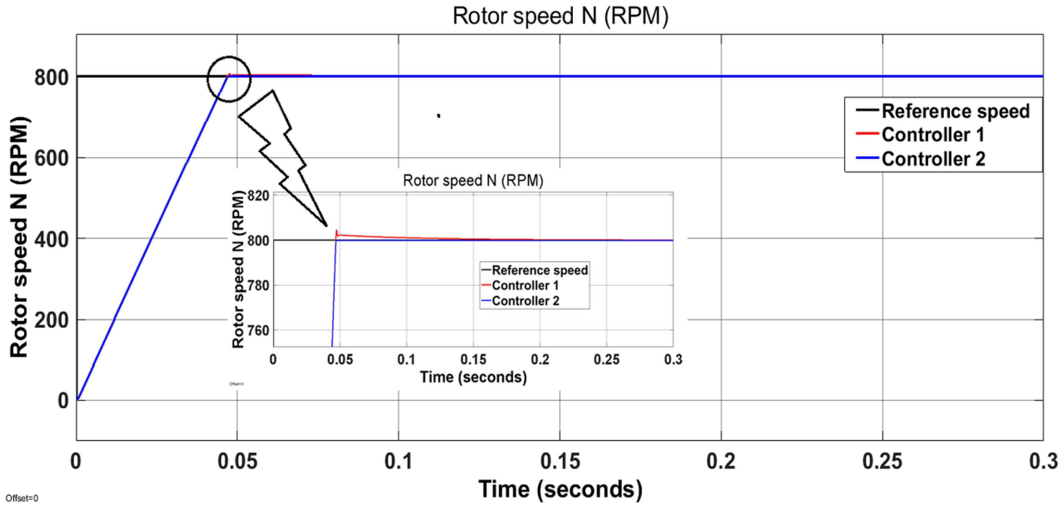
A profile-based feedback controller is proposed for setting the six-pulse inverter frequency and parameters of the PWM waveform for current control based on Hall sensor position, and the same is implemented for the closed loop operation of the brushless direct current motor drive system. The speed response of the two different controllers, controller 1 and controller 2, are shown in
Figure 11, and its expanded view depicts that controller 2 provided a smoother response compared with controller 1. In contrast, controller 1 has a higher amount of overshoot, which is quite evident in the expanded view. Moreover, controller 1 and controller 2 had different gain parameters selected for obtaining better performance.
Table 4 shows the ratings and parameters of the BLDC motor used in this paper.
6. Hardware Setup
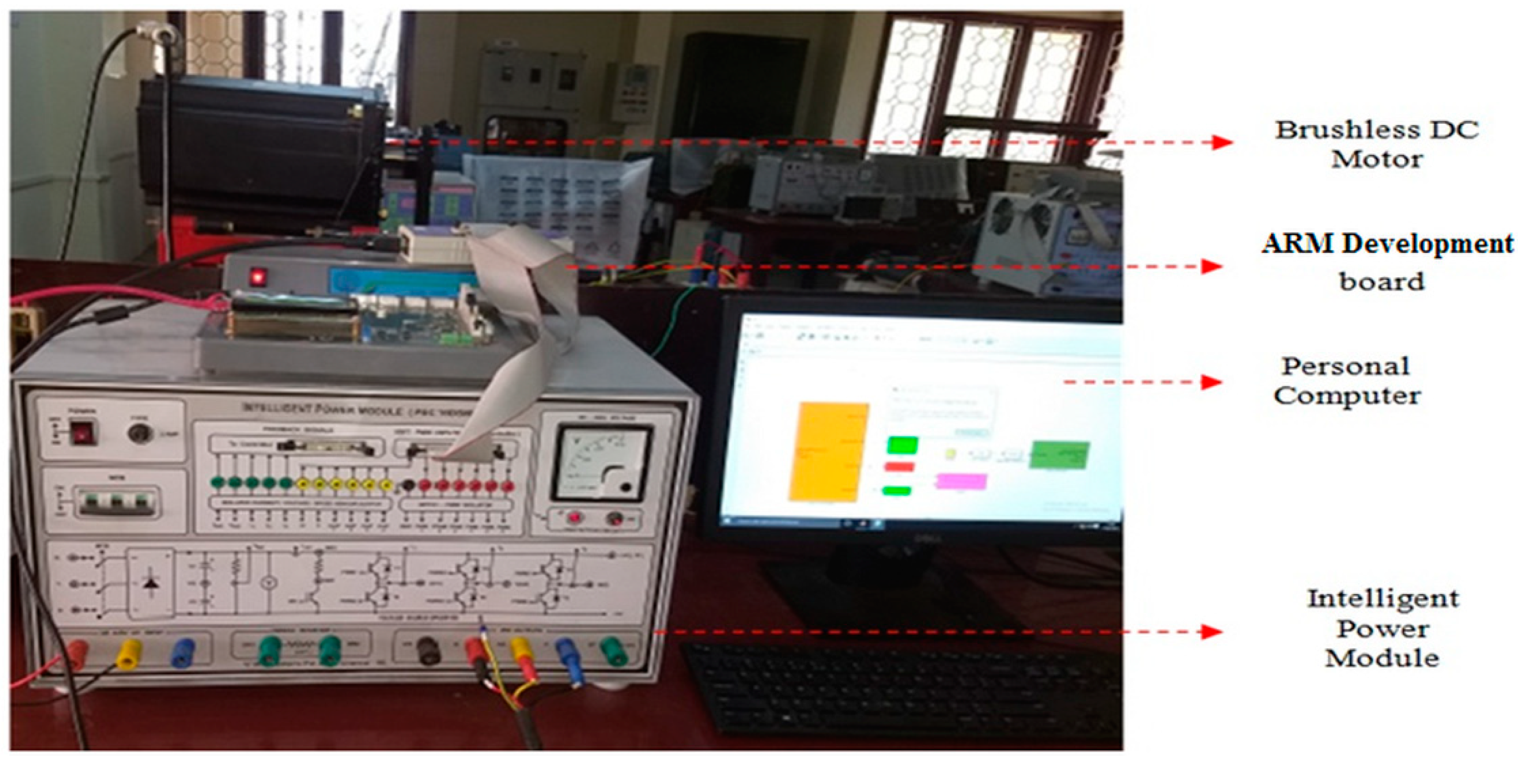
Figure 12 illustrates the hardware setup of the drive system employed for the research, in a laboratory-based environment. It consisted of an IGBT-based intelligent power module (IPM), the brushless direct current (BLDC) motor belt coupled to a direct current (DC) generator, and the load arrangements. For the drive system to operate in a closed-loop mechanism, an ARM development board with speed sensors and interfaces was employed. A three-phase alternating current (AC) supply fed the bridge rectifier for obtaining the DC supply to drive the BLDC motor. The generated reference parameters were compared with the actual parameters, as discussed earlier, by means of a suitable controller mechanism. A CPU that was interfaced with the BLDC motor drive system was employed for monitoring the actual and reference speeds. This can be clearly observed from the screen display in
Figure 12.
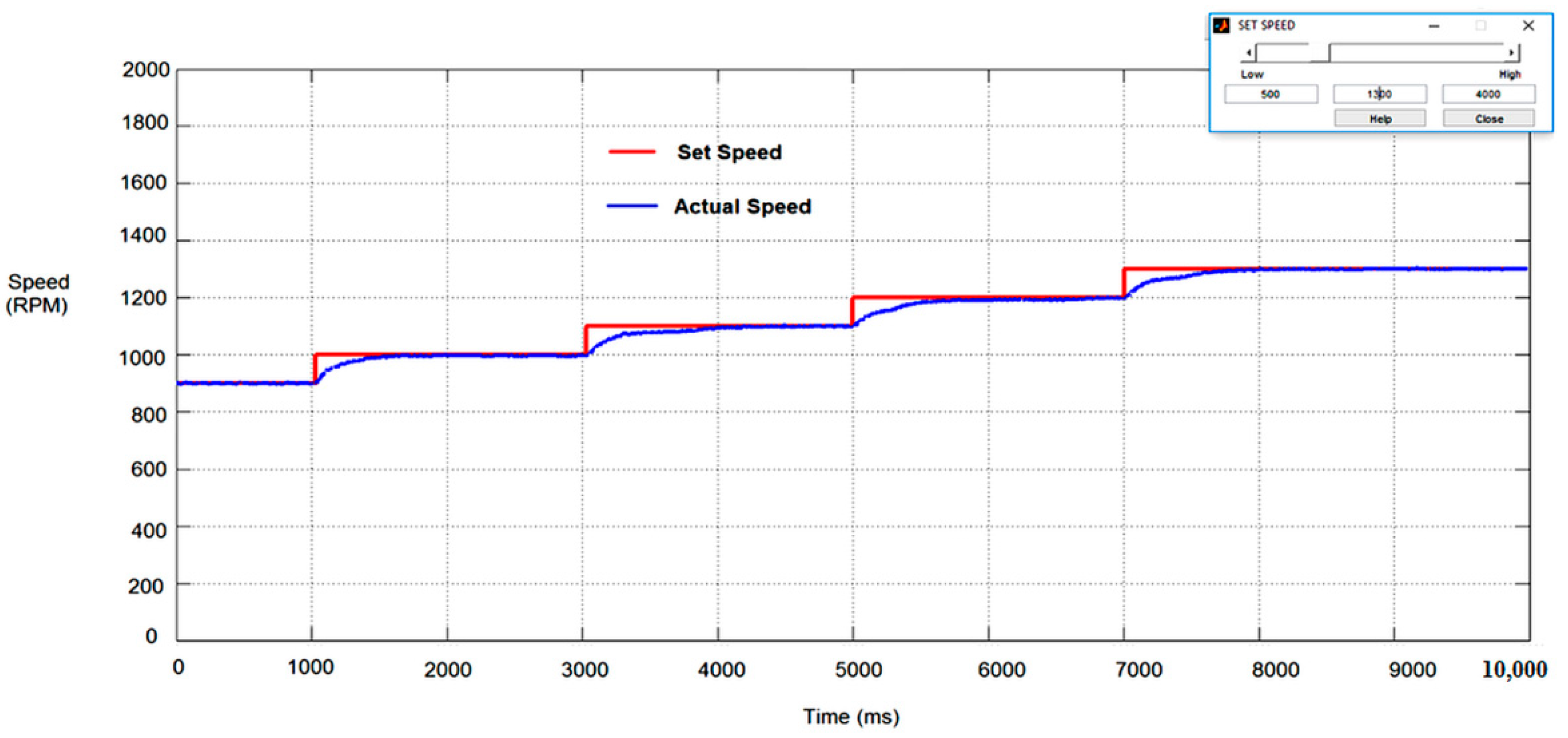
The actual rotor speed of the BLDC motor, following the set or reference speed is shown in
Figure 13. The reference speed ranges from 900 RPM to 1300 RPM, with incremental steps of 100 RPM. A red-colored line indicates the reference or set speed, which was set by the user and accordingly the motor speed tracked the set speed indicated in a blue color.
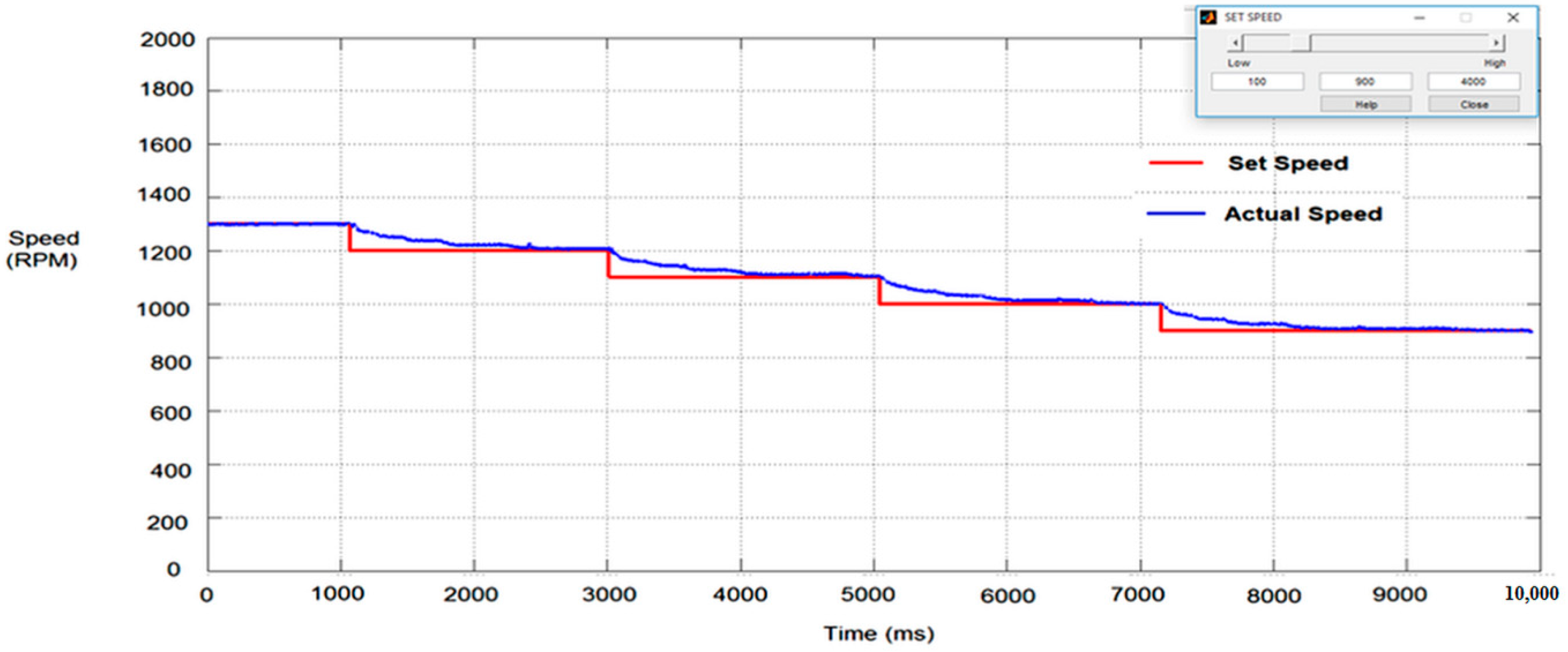
The forward motion of the Brushless DC motor tracked the set or reference speed with decreasing values spanning from 1300 RPM to 900 RPM in steps of 100 RPM, as shown in
Figure 14.
7. Conclusions
A total system for hot rough steel rolling, consisting of a BLDC motor drive, coupled to a set of work rolls and backup rolls, along with a closed loop controller, with a multi-loop configuration has been presented in this paper. The set of mathematical equations covering the steel rolling process, the BLDC motor model, and the controller model have been developed for simulation. The simulation results, corresponding to the first and third quadrant operation of the BLDC motor drive system, for a multi-pass steel roughing mill of a 1005 hot rolled steel feed specimen, have been obtained. A profile-based controller has been successfully employed for the smooth operation of the entire system. Furthermore, the performance of the drive system proved it to be an efficient mechanism for fast hot rolling. Hence, it is concluded that a BLDC-motor-based drive system, as presented in this paper, can serve as a powerful replacement for the traditional induction motor drive systems that have been employed for steel rolling, thereby eliminating the need for front-end converters, which in turn eliminates the cost of equipping the components used in them, and, thus, also improving the conversion efficiency.
Author Contributions
M.N. performed the work under the guidance and direction of S.R., S.N. and S.S.R. All authors analyzed the data and contributed towards the paper. M.N. wrote the paper and executed the experiments under the guidance and supervision of, and with suggestions from, S.R., S.N. and S.S.R. All authors also have contributed towards writing and editing the paper. All authors have read and agreed to the published version of the manuscript.
Funding
This research received no external funding.
Acknowledgments
The authors thank the SASTRA Deemed University for providing all of the facilities in the research lab of Power Electronics & Drives that were used to carry out the research.
Conflicts of Interest
The authors declare no conflict of interest.
References
- Math Works. The Math Works—MATLAB and Simulink for Technical Computing. 2016. Available online: http://www.mathworks.com (accessed on 7 September 2016).
- Gamazo-Real, J.C.; Vázquez-Sánchez, E.; Gómez-Gil, J. Position and Speed Control of Brushless DC Motors Using Sensorless Techniques and Application Trends. Sensors 2010, 10, 6901–6947. [Google Scholar] [CrossRef] [PubMed]
- Mahfouf, M.; Yang, Y.Y.; Gama, M.A.; Linkens, D.A. Roll speed and Roll Gap control with Neural Network Compensation. ISIJ Int. 2005, 45, 841–850. [Google Scholar] [CrossRef]
- Masood, R.J.; Wang, D.B.; Ali, Z.A.; Khan, B. DDC Control Techniques for Three-Phase BLDC Motor Position Control. Algorithms 2017, 10, 110. [Google Scholar] [CrossRef]
- Chattopadhyay, A.K. Alternating Current Drives in the Steel Industry, Advancements in the last 30 years. Ind. Electron. Mag. 2010, 4, 30–42. [Google Scholar] [CrossRef]
- Kun, E.; Szemmelveisz, T. Energy efficiency enhancement in the Hot Rolling Mill. Mater. Sci. Eng. 2014, 3, 4350. [Google Scholar]
- Rodríguez, J.R.; Pontt, J.; Newman, P.; Musalem, R.; Miranda, H.; Morán, L.; Alzamora, G. Technical Evaluation and Practical Experience of High-Power Grinding Mill Drives in Mining Applications. IEEE Trans. Ind. Appl. 2005, 41, 866–873. [Google Scholar] [CrossRef]
- Lotter, U.; Schmitz, H.-P.; Zhang, L. Application of the Metallurgically Oriented Simulation System “TKS-StripCam” to predict the properties of Hot Strip Steels from the Rolling Conditions. Adv. Eng. Mater. 2002, 4, 207–213. [Google Scholar] [CrossRef]
- Yamada, F.; Sekiguchi, K.; Tsugeno, M.; Anbe, Y.; Andoh, Y.; Forse, C.; Guernier, M.; Coleman, T. Hot Strip Mill Mathematical models and SetUp Calculation. IEEE Trans. Ind. Appl. 1991, 27, 131–139. [Google Scholar] [CrossRef]
- Orcajo, G.A.; Rodríguez, J.; Ardura, P.; Cano, J.M.; Norniella, J.G.; Llera, R.; Cifrián, D. Dynamic Estimation of Electrical Demand in Hot Rolling Mills. In Proceedings of the IEEE Industry Applications Society Annual Meeting 2015, Dallas, TX, USA, 18–22 October 2015. [Google Scholar]
- Gieras, J.F. Permanent Magnet Motor Technology, Design and Applications; Second Edition Revised and Expanded; CRC Press: Boca Raton, FL, USA, 2002. [Google Scholar]
- Niknejad, P.; Agarwal, T.; Barzegaran, M.R. Utilizing Sequential Action Control Method in GaN-Based High-Speed Drive for BLDC Motor. Machines 2017, 5, 28. [Google Scholar] [CrossRef]
- Miller, T.J.E. Brushless Permanent Magnet & Reluctance Motor Drives; Clarendon Press: Oxford, UK, 1989; Volume 2, pp. 192–199. [Google Scholar]
- ASM International. ASM Metals Handbook, vol.14, Forming and Forging; ASM International: Novelty, OH, USA, 1996; pp. 351–355. [Google Scholar]
- Groover, M.P. Fundamentals of Modern Manufacturing. Materials, Processes and Systems, 4th ed.; John Wiley & Sons: Hoboken, NJ, USA, 2010; pp. 395–403. [Google Scholar]
- AISI/SAE Standard (American Iron and Steel Institute/Society of Automotive Engineers); SAE J403 1050; SAE: Warrendale, PA, USA, 2014.
- Cunkas, M.; Aydoğdu, O. Realization of Fuzzy Logic Controlled Brushless DC Motor Drives Using Matlab/Simulink. Math. Comput. Appl. 2010, 15, 218–229. [Google Scholar]
- Singh, B.; Bist, V. An improved power quality bridgeless Cuk converter fed BLDC motor drive for air conditioning system. IET Power Electron. 2013, 6, 902–913. [Google Scholar] [CrossRef]
- Pillay, P.; Krishnan, R. Modeling, simulation, and analysis of permanent- magnet motor drives, part II: The brushless dc motor drive. IEEE Trans. Ind. Appl. 1989, IA-25, 274–279. [Google Scholar] [CrossRef]
- Nandakumar, M.; Ramalingam, S.; Nallusamy, S.; Rangarajan, S.S. Novel efficacious utilization of Fuzzy Logic Controller based Two-quadrant operation of PMBLDC Motor Drive System for Multi-Pass hot steel rolling Process. Electronics 2020, 9, 1008. [Google Scholar] [CrossRef]
© 2020 by the authors. Licensee MDPI, Basel, Switzerland. This article is an open access article distributed under the terms and conditions of the Creative Commons Attribution (CC BY) license (http://creativecommons.org/licenses/by/4.0/).

 ,
, 


