Article

On the DC Offset Current Generated during Biphasic Stimulation: Experimental Study

Department of Electrical and Computer Engineering, National University of Singapore, Singapore 117583, Singapore
Electronics 2020, 9(8), 1198; https://doi.org/10.3390/electronics9081198
Submission received: 30 June 2020 / Revised: 20 July 2020 / Accepted: 22 July 2020 / Published: 25 July 2020
(This article belongs to the Special Issue Design and Application of Biomedical Circuits and Systems)

Abstract

:
This paper deals with the DC offset currents generated by a platinum electrode matrix during biphasic stimulation. A fully automated test bench evaluates the nanoampere range DC offset currents in a realistic and comprehensive scenario by using platinum electrodes in a saline solution as a load for the stimulator. Measurements are performed on different stimulation patterns for single or dual hexagonal stimulation sites operating simultaneously and alternately. The effectiveness of the return electrode presence in reducing the DC offset current is considered. Experimental results show how for a defined nominal injected charge, the generated DC offset currents differ depending on the stimulation patterns, frequency, current amplitude, and pulse width of a biphasic signal.

1. Introduction

Neural stimulation shows reliable effectiveness in concrete cures where traditional medication is not as effective at reducing tremors in epilepsy or in restoring the sight in a person affected by retinitis pigmentosa. To elicit nerve activities, tissues are usually excited by zero-net charge biphasic current pulses [1], whose features are reported in Figure 1. The first cathodic pulse usually elicits the desired neural response, while the second pulse only aims to neutralize charge across the stimulated tissues. A perfect charge balance in the neural stimulator, such as cochlear or retinal integrated circuit (IC) implants, is required to avoid DC currents or electrode resting potentials that can generate toxic species and, in turn, damage tissues [2,3,4,5,6,7,8,9,10,11].
The charge during the opposite phases of sourcing and sinking currents should be balanced, as well as the impedance of the electrodes needs to be perfectly matched. For this purpose, several techniques and stimulation strategies for a precise charge balancing have been proposed at the IC level to minimize the undesired DC offset current generated by the biphasic stimulation [12,13,14,15,16,17,18].
During a biphasic stimulation, each platinum electrode in the saline bath defines an electrode-electrolyte interface while a charge is injected through faradaic and non-faradaic charge-transfer mechanisms. These can lead to changes in the surface chemistry of the platinum electrodes under study and are the source of DC offset currents originating at the electrode-electrolyte interface [19]. On this basis, IC designers for biomedical devices have shown a relevant effort to reduce any mismatch between the current sources that provide the biphasic pulse at the electrodes-tissue interface. The more macroscopic each electrode-tissue interface’s size, the more significant is the mismatch over time and between implantees. This represents a bottleneck in the DC offset current generation. Based on the weakness of the signal to monitor (tens of nanoamperes), the DC offset current value in the literature usually refers to CAD simulation or measurements where the electrodes and the tissues are substituted with an equivalent quasi-static loss electric model constituted by passive components (resistor in series with a parallel capacitor and resistor). Moreover, such a DC offset current value reported in the literature relates to a defined stimulation pattern and a specific set of electrical parameters of the biphasic signal [12,13,14,15,16,17,18].
In this paper, the DC offset currents generated by a neural IC implant that provides the current stimulation through a platinum electrode matrix placed in a saline bath are investigated. This is because measurement results performed with physiological saline emulate at best the real case where the electrodes interface with tissues in neural implantation. The most common hexagonal stimulation patterns operating in different conditions of biphasic pulses’ amplitude and duration have been analyzed. An automatic measurement setup aimed to monitor DC offset current is described in Section 2. Then, the procedure for a reliable data acquisition is shown in Section 3. In Section 4, the measurement results according to a different frequency, amplitude, and duration of the biphasic pulses and for different stimulation patterns are shown. The DC offset currents of two hexagonal stimulation sites operating simultaneously or stand-alone are investigated. In Section 5, the conclusions are drawn.

2. Measurement Setup

2.1. System Overview

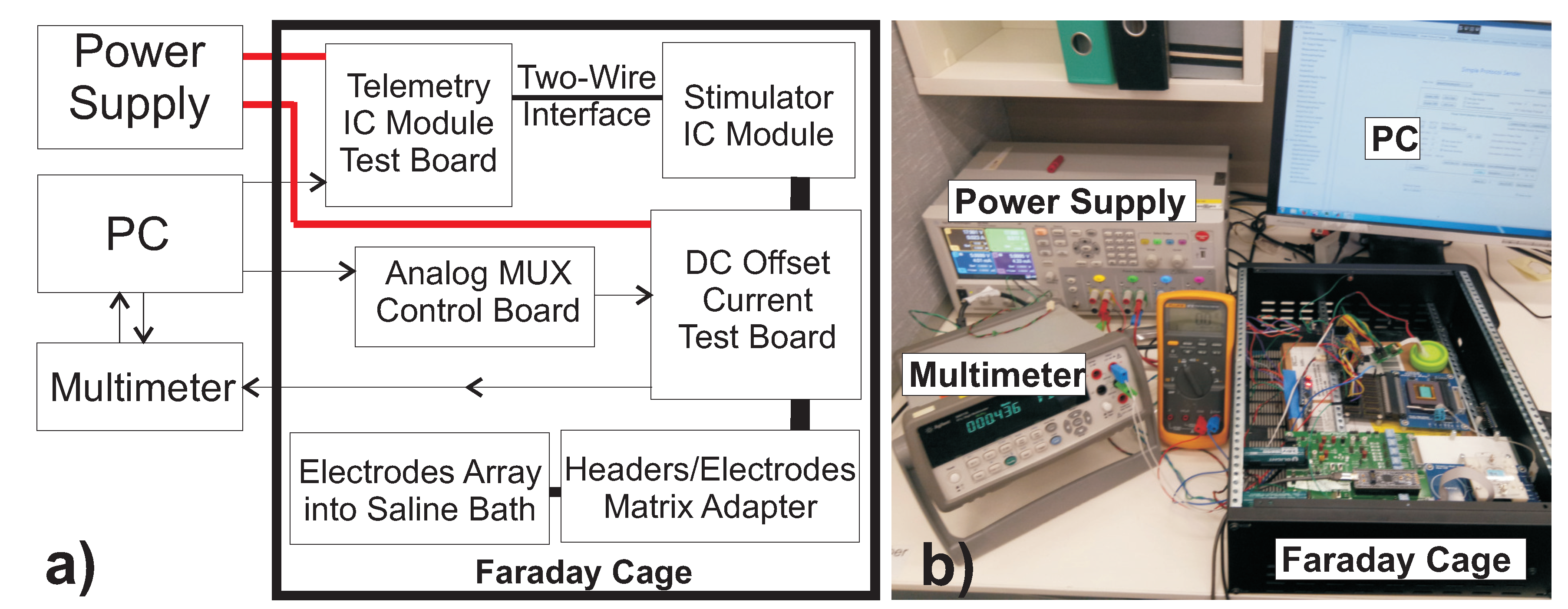
The purpose of the measurement test bench is to monitor the DC offset currents generated by platinum electrodes in a saline bath when they are actively driven by a neural stimulator. This is to validate the safety of the overall system (from the neural IC implant to the electrode matrix), as well as the chosen stimulation regime. The sketch of the DC offset current measurement test bench and the respective photo are shown in Figure 2.
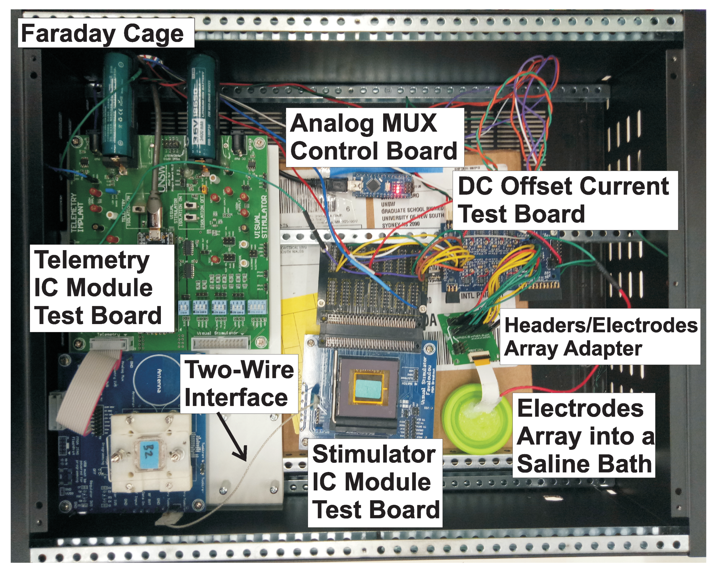
Such a test bench is remotely controlled by a personal computer (PC in Figure 2) running an automated test bench (USB controlled by Matlab) aimed to measure DC offset currents through a statistical approach based on data storage redundancy to achieve valuable results. Notice that because of the weak nature of the signal to be monitored, the measurement setup is placed into a metal enclosure that acts as a Faraday cage. Such metal enclosures help in minimizing power line interference, external noise, and any rapid drift in temperature and airflow during the measurements. Figure 3 shows the content of the Faraday cage. A graphic interface defines the stimulation pattern sending the related protocol to the telemetry module (left side in Figure 3). This, in turn, sets the electric specifications of the biphasic current pulses of the IC stimulator through a fully differential two-wire interface. The IC neural stimulator employed in the investigation reported in this paper [18] is placed into a specific module test board (bottom-center in Figure 3). Each of the biphasic currents delivered by the neural stimulator flow through a sense resistor mounted on the test board to the respective electrode in a saline bath (bottom-right in Figure 3).

2.2. DC Offset Current Detection Test Board

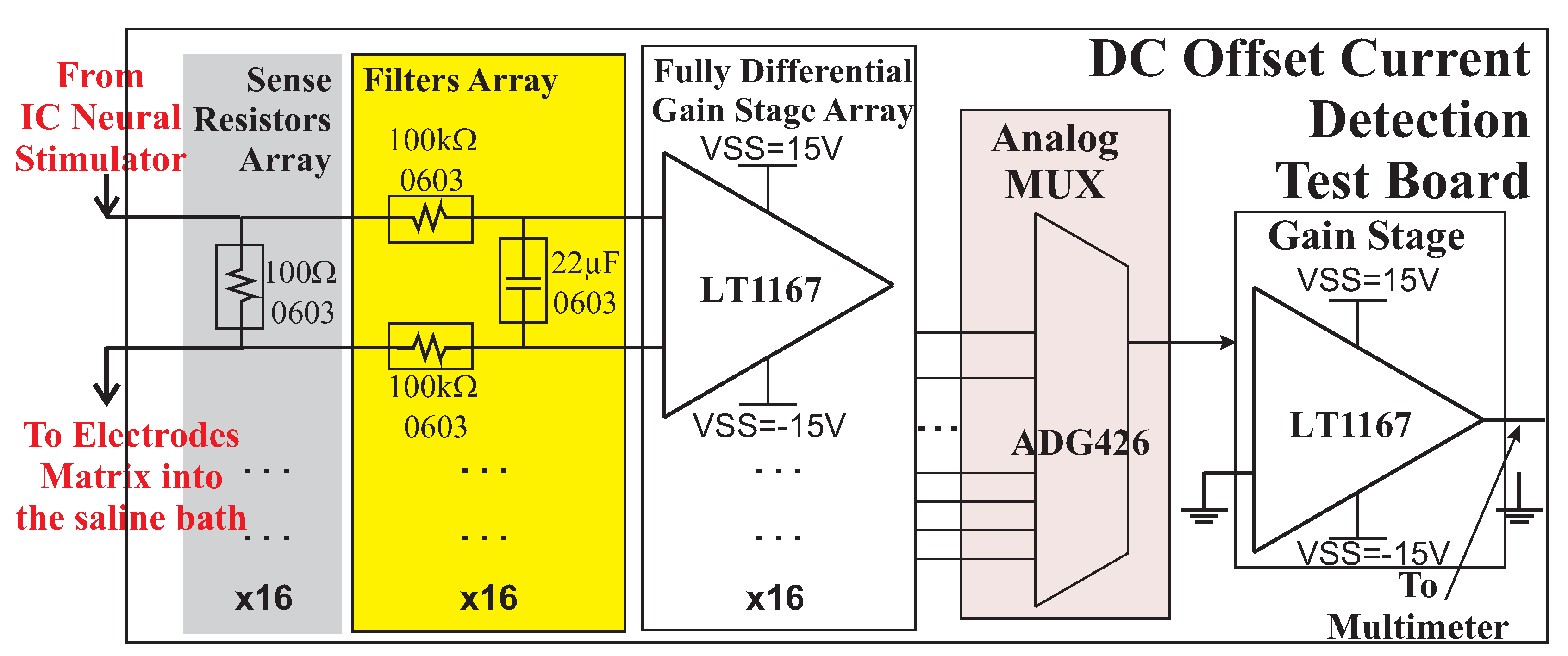
The test board represented in Figure 4 allows the detection of the DC offset currents by means of the voltages produced by each biphasic current pulse flowing through a sense resistor. Indeed, such voltages are low pass filtered before being amplified by a cascade of two low offsets, low input bias current instrumentation amplifiers (Linear Technology, LT1167 [20]) for each channel (Figure 4). Since the system needs to measure DC offset current lower than 100 nA across a sense resistor of 100 Ω , corresponding to a voltage drop of 10 μ V , two gain stages are used. In order to circumvent the increase in required PCB area and system cost, the final design consists of 16 copies of the instrumentation amplifier. The outputs from such amplifiers are subsequently multiplexed to a second stage instrumentation amplifier with a gain of 100 via an analog multiplexer (ADG426 [21]). The overall system can evaluate current adequately down to 10 nA. The acquired data are sent to the microcontroller (analog MUX control board in Figure 2a and Figure 3) via USB. Such a microcontroller drives the analog multiplexer on the PCB where the above-mentioned matrix of sense resistance and the cascade gain stage are placed. The output of the analog multiplexer is measured by a multimeter (Agilent 34411A) that is interfaced with the personal computer via USB (as in Figure 2).

2.3. Platinum Electrodes Matrix

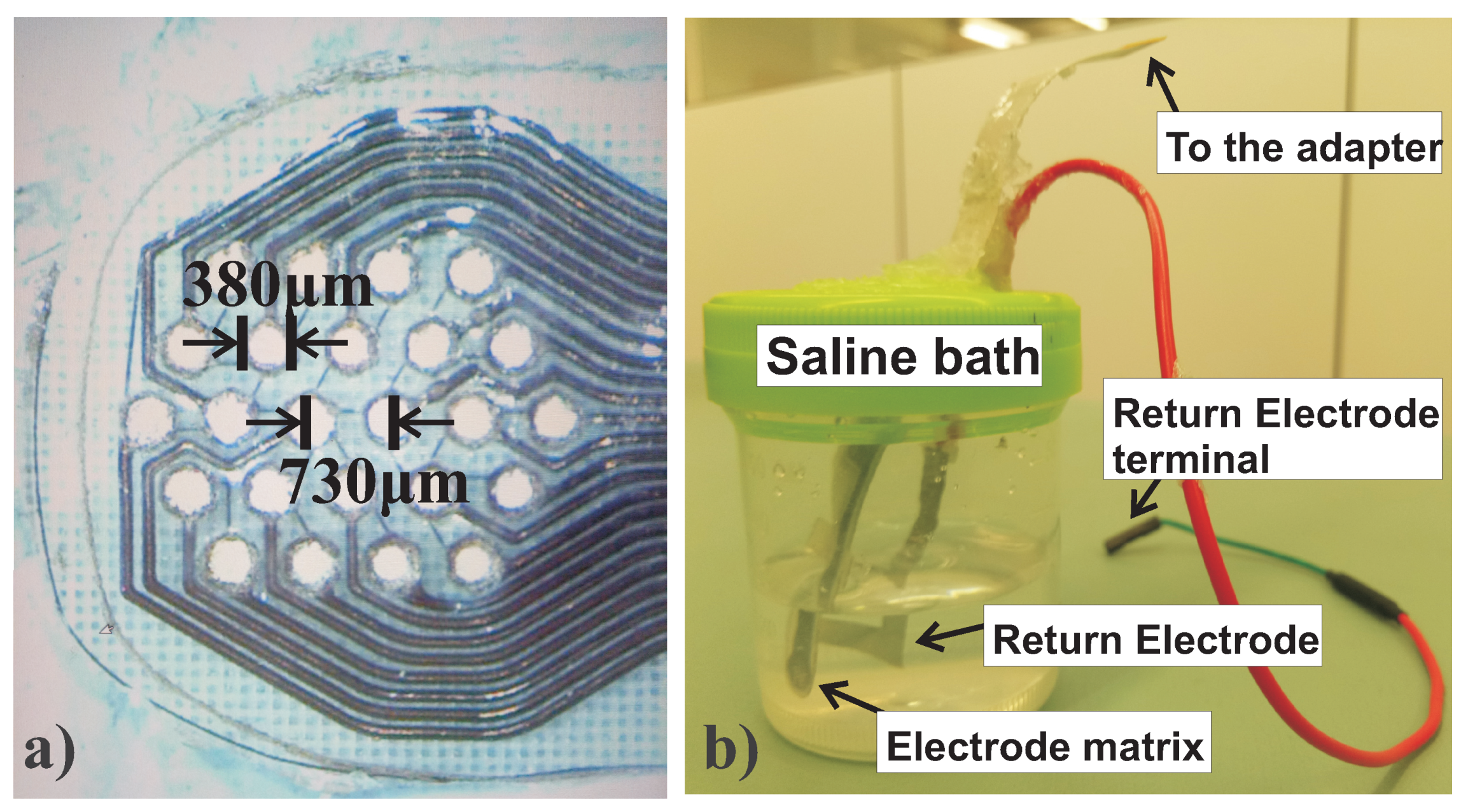
A matrix consisting of 24 electrodes (Figure 5a [22]) is placed into a saline bath with another single bigger electrode as in Figure 5b. Both are inserted and isolated (through silicone) into a slot on the lid of a sample jar containing the artificial physiological saline solution. The bigger electrode is employed as the monopolar return used to assess the quasi-monopolar stimulations pattern described in Section 3. The platinum electrodes are hermetically enclosed in a physiological saline bath using silicone. This is to keep the same ion concentration in the saline bath so that the physiological saline does not need to be replaced every new day of measurements. Moreover, thanks to the silicone’s presence, a reciprocal distance between the electrode matrix and the return electrode (≈1 cm) is set.

3. Stimulation Procedures And Methods

3.1. Preliminary Procedures

Before providing the biphasic stimulation and running the DC offset current measurements, a robust setup has to be built taking into account the critical interfacing with the electrodes in a saline bath. For this reason, the electrode matrix was carefully cleaned and connected to the neural IC implant according to the following procedures. First, a drop of 80% ethanol solution is applied on the electrode matrix and to facilitate the gentle removal of the accumulated particles (if any) on the surface of the electrodes with the tip of a tweezer. Indeed, particles can lay on the surface of the electrodes as a result of ionic impurities within the saline solution (i.e., silicone employed for the electrode matrix and return electrode (RE) enclosure in the saline bath) after long runs of measurements with the same saline bath. After this first cleaning, the electrode matrix is rinsed and left in deionized water for a few hours before starting DC offset current measurements. Then, the electrode matrix is immersed into the saline bath and connected to the respective terminals through an adapter. This adapter is then connected to the headers of the DC offset current detection test board. As a final check of the connections of the entire measurement setup (neuro IC implant, DC offset current test board, header/electrodes adapter, and electrode matrix in the saline bath), the biphasic pulse is visualized with a scope. The probe-scope is then removed during the measurement procedures. To avoid current flowing into the diode of the amplifiers, the voltage supply dynamic range of the amplifier on the DC offset current test board has to be higher ( ± 15 V) than the voltage dynamic range of the neural stimulator (12 V).

3.2. Stimulation Patterns

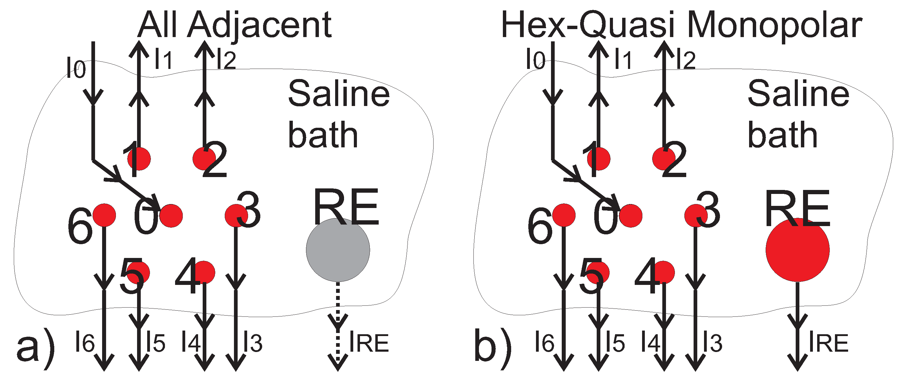
The two most common retinal stimulation patterns employed to restore the sight in visually impaired persons are sketched in Figure 6 where they are named as the All Adjacent (AA) and the Hex Quasi-monopolar (HQ) return configurations. In both configurations, the electrodes are arranged in a hexagonal pattern that represents the elementary stimulation site. In the All Adjacent configuration (Figure 6a), the current flows to the tissues from the center of the hexagon, and the current return path is through the six surrounding electrodes [23]. This stimulation arrangement ensures that the stimulation current flow is localized to each hex center, but at the same time, such localized current flow reduces the current flow to excitable tissue when compared with stimulating against a distant return electrode. For this reason, an improved stimulation approach is represented by the hex quasi-monopolar configuration sketched in Figure 6b. In this approach, in addition to the localized hexagon site, the current can also flow to a distant, large, and low-impedance monopolar return electrode located on the stimulating module capsule. This arrangement allows for a decrease in the power drawn by the system [24].

3.3. Stimulation Specifications

The maximum current amplitude and pulse duration of the biphasic stimulation is related to the charge injection limit (maximum value of 210 μ C / cm 2 ) [3]. This results in a maximum charge delivery of 238 nC (per electrode and per phase) for electrodes with an opening of 380 μ m in diameter. Note that the geometric surface area is conservatively used in the determination of electrode charge-carrying capacity. On this basis, the maximum pulse duration is set equal to T P U L S E M A X = 500 μ s , and the maximum current capability of the stimulator under test is limited to I P U L S E M A X = 460 μ A . Therefore, the maximum charge delivery per phase is equal to:
Q P U L S E M A X = I P U L S E M A X · T P U L S E M A X = 230 nC
and just lower than the above-mentioned value. The interphase delay is equal to 5 μ s as an IC stimulator constraint. The relevant stimulation frequencies of 50 Hz and 25 Hz were considered.

3.4. Measurements Procedures

An automated test bench developed to collect the DC offset operates according to the following steps. First, the neural stimulator is turned off to measure the offset of the amplification chain. The offset voltage of each cascade gain stage is stored, and the measurement is repeated 100 times to find the average value of the offset voltage for each channel. Then, the neural IC implant is turned on according to a defined pattern. The acquisition system waits for two minutes before starting to collect data to avoid any starting drift phenomena. This procedure is repeated 100 times, and an average voltage value is calculated for each channel. Subtracting such data from the respective offset, the voltage drop due to DC offset current and to the test bench is calculated.
The investigation is focused on the trend of DC offset current generation with different biphasic signal features like frequency, current amplitude, pulse width, and the reciprocal interaction among stimulation sites. Because of the weak nature of the signal to detect, the measurement results are reported considering average values and the respective range of variability equal to ± 3 σ where σ is the standard deviation.

4. Measurement Results

The DC offset current generated by platinum electrodes during biphasic stimulation in a saline bath is investigated firstly referring to the All Adjacent and the Hex Quasi-monopolar stimulation patterns for a single excitation site. Based on these results, the investigation will be focused on the Hex Quasi-monopolar stimulation pattern considering two hexagonal excitation sites operating simultaneously and with a stimulation frequency of 25 Hz and 50 Hz. A sweep of current amplitude I P U L S E for a constant pulse width T P U L S E is first considered. Then, a sweep of the pulse width T P U L S E to a constant current amplitude I P U L S E is reported. In this way, for a charge pulse nominally equal to Q P U L S E = I P U L S E · T P U L S E , a different contribution of the current amplitude I P U L S E and of the pulse width T P U L S E on the overall DC offset current generation can be highlighted. As a final analysis, such a DC offset current generated by two hexagonal excitation sites operating simultaneously is compared with the sum of the DC offset currents of each hexagonal site operating stand-alone with the return electrode.

4.1. All Adjacent and Hex Quasi-Monopolar Stimulation Patterns’ Comparison

As depicted in Figure 6a,b respectively for the All Adjacent and the Hex Quasi-monopolar stimulation patterns, the stimulation current I P U L S E flows into the saline bath from the central electrode (labeled 0) to the surrounding ones (labeled 1 to 6) and to the return electrodes (REs). The math relation among the stimulation current for each electrode can be written as:
I P U L S E = I 0 = j = 1 6 I j + I R E
Thus, accordingly, the respective DC offset current of the central electrode i 0 is split into the others:
i 0 = j = 1 6 i j + i R E
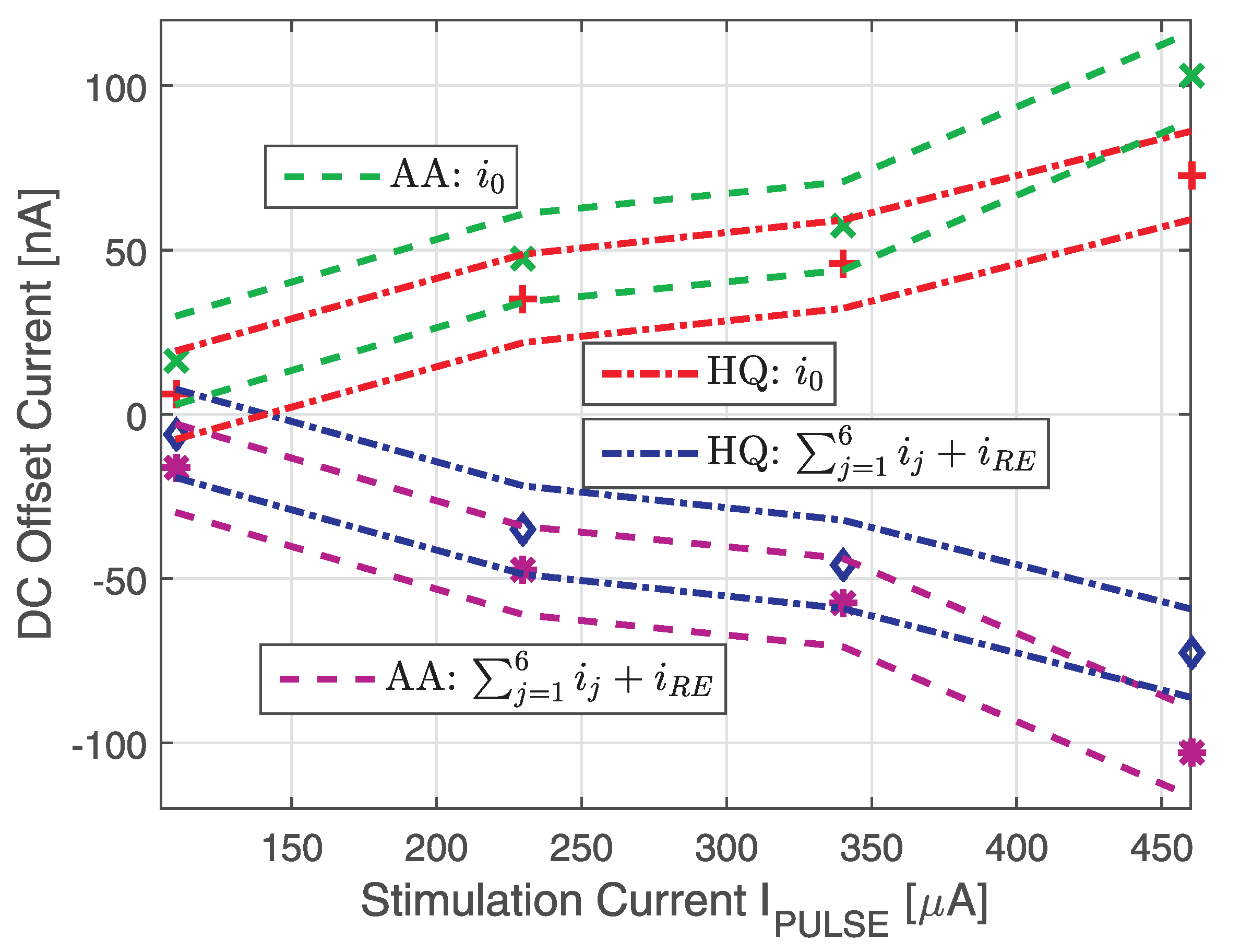
Therefore, the DC offset current from the central electrode i 0 is much higher than the others for each hexagon excitation site. In Figure 7, this current i 0 and the sum of the others versus the biphasic current amplitude at the pulse width T P U L S E = T P U L S E M A X = 500 μ s are reported. Measurements were performed on a single stimulation site for both the All Adjacent and the Hex Quasi-monopolar stimulation patterns. Since the DC offset currents come from a relative mismatch between the anodic and cathodic charges’ path in the stimulator, it increases with the current stimulation amplitude. These measurements highlight how a Hex Quasi-monopolar stimulation pattern offers a reduced DC offset current compared with the All Adjacent configuration. This is due to the role of the return electrode (RE). In such a bigger electrode, current flows from all the active hexagons site belonging to the electrode matrix. This occurs even in the All Adjacent return configuration that nominally should not require the return electrode. In fact, at the end of each biphasic period, all the electrode terminals are shorted together. Thus, because of its bigger size, the return electrode has a higher residual charge flowing in it. As a consequence, the return electrode presence offers a common path to flow for the DC offset currents coming from the electrode matrix. This, in turn, implies a reduction of the DC offset current spreading across the electrodes in the matrix. For this reason, the Hex Quasi-monopolar pattern in which the return electrode is actively involved in the stimulation shows a reduced DC offset current as reported in Figure 7. On this basis, the Hex Quasi-monopolar stimulation pattern is the preferred one in a real experiment and further considered in the following.

4.2. Hex Quasi-Monopolar Multi-Site Excitation

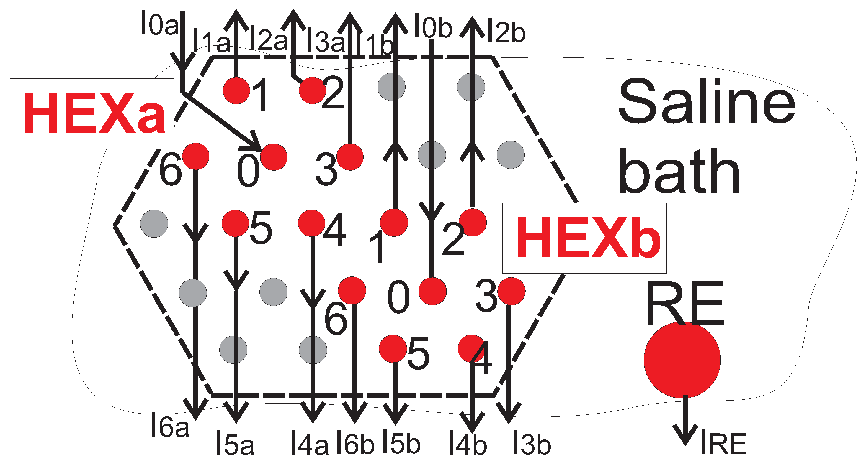
In a practical case, the electrode matrix is made of tens of multiple hexagonal stimulation sites alternately activated that share the same return electrode [12,13,14,15,16,17,18]. Figure 8, representing two hexagonal stimulation sites HEXa and HEXb that are simultaneously active and share the same return electrode. The mathematical relationship among the stimulation currents I for a Hex Quasi-monopolar stimulation pattern is:
2 · I P U L S E = I 0 a + I 0 b = j = 1 6 ( I j a + I j b ) + I R E
so that for the respective DC offset currents, i can be written as:
i 0 a + i 0 b = j = 1 6 ( i j a + i j b ) + i R E
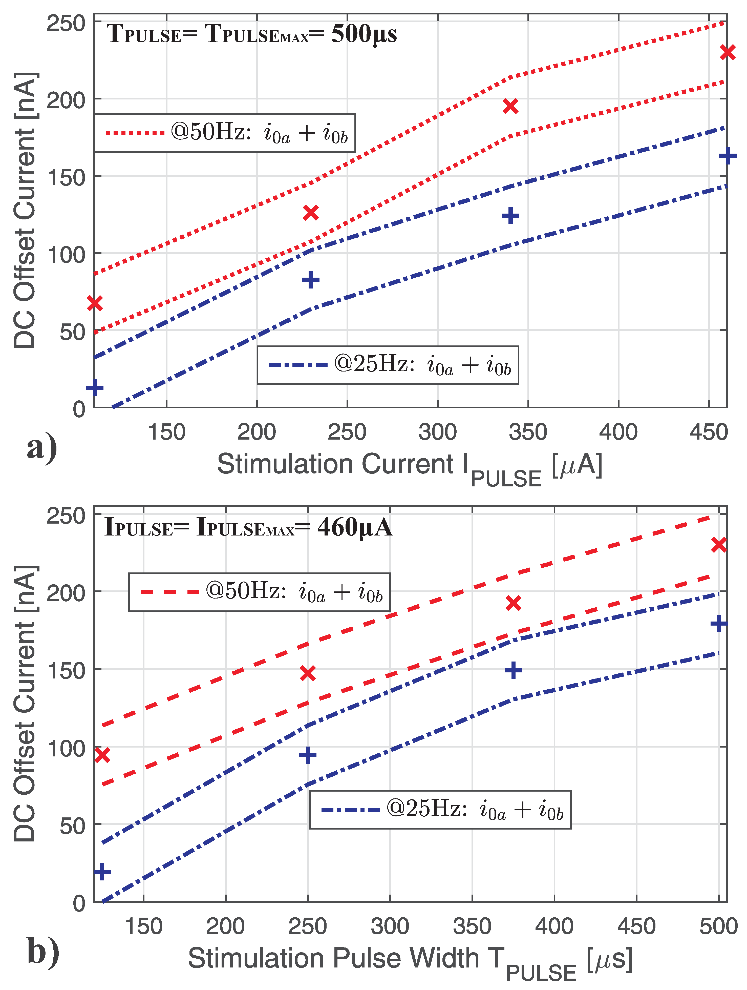
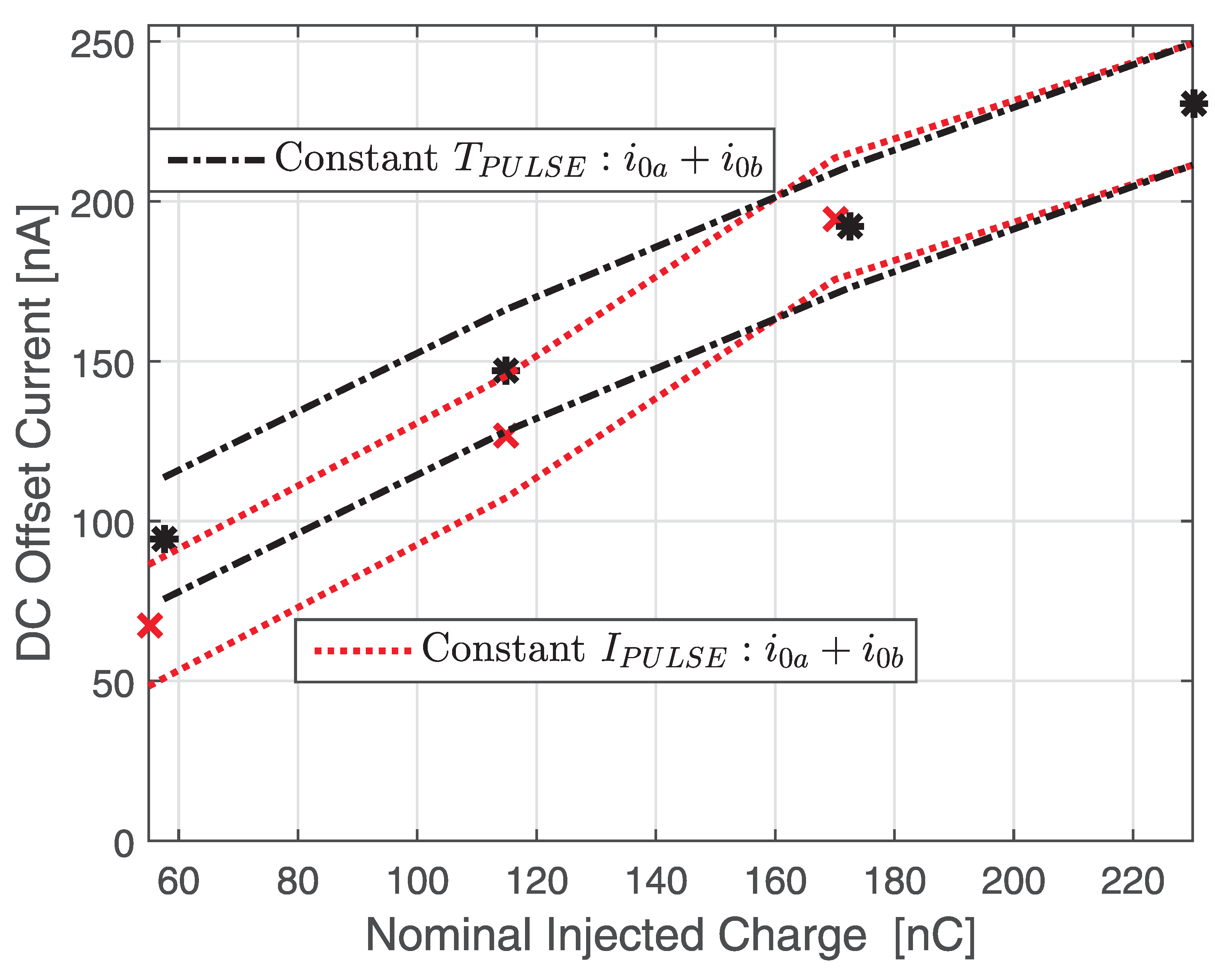
The sum of the DC offset currents of the central electrodes for two hexagonal sites i 0 a + i 0 b into their respective standard deviation range has to match in absolute value with the sum of the DC offset currents of the other electrodes. Nevertheless, not only the DC offset currents of such a central electrode, but even those of every electrode involved in the stimulation were acquired. This was to check the effectiveness of the measurement system and, thus, the validity of the acquired data. After having considered this in every measurement run, for simplicity and clarity, only the DC offset currents of the central electrodes are reported in the following measurement results. The current amplitude I P U L S E of each hexagonal site was swept (from I P U L S E M A X / 4 to I P U L S E M A X ) keeping the same pulse duration T P U L S E M A X = 500 μ s as shown in Figure 9a for a biphasic signal frequency of 50 Hz (range among the dashed red lines) and 25 Hz (range among the dash-dotted blue lines). Similarly, the pulse width T P U L S E was swept (from T P U L S E M A X / 4 to T P U L S E M A X ) keeping the same pulse duration I P U L S E M A X = 460 μ A as shown in Figure 9b for a biphasic signal frequency of 50 Hz and 25 Hz. This is to highlight the respective contribution to the overall DC offset current spread into the saline. In both of these measurement results, stimulation frequencies of 50 Hz and 25 Hz are reported. The comparison of these results highlights how lowering the frequency of the biphasic signal reduces the DC offset current. This implies that the mismatch between the anodic and cathodic charge pulses depends on their timing to reach the nominal stimulation current values I P U L S E and I P U L S E in the two stimulation phases. Notice that in Figure 9a,b, the absolute mismatch increases with an increased absolute charge entity Q P U L S E = I P U L S E · T P U L S E during the stimulation. However, lowering the amplitude of the current pulses I P U L S E for a given pulse duration T P U L S E (as in Figure 9a) reduces the DC offset current more than lowering the pulse duration T P U L S E for a given current pulse amplitude I P U L S E (as in Figure 9b). To better highlight which one among current amplitude I P U L S E and pulse width T P U L S E contributes more to the DC offset current generation, the same data reported in Figure 9a,b are translated in Figure 10 into the respective nominal charge provided during biphasic stimulation, referring to a 50 Hz frequency.
In Figure 10, the nominal injected charge Q P U L S E = I P U L S E · T P U L S E versus the DC offset current for a constant stimulation current I P U L S E = I P U L S E M A X = 460 μ A (range among the dashed red lines for the sum of the two central electrodes’ DC offset currents i 0 a + i 0 b ) and for a constant pulse width T P U L S E = T P U L S E M A X = 500 μ s (range among the dash-dotted black lines for the sum of the two central electrodes’ DC offset currents i 0 a + i 0 b ). The comparison shows how for a given injected charge Q P U L S E = I P U L S E · T P U L S E , the DC offset current is reduced with a shortened pulse width T P U L S E and choosing the current amplitude I P U L S E accordingly. As a result, the stimulation timing both in terms of frequency and pulse width amplitude is the most critical in DC offset current generation. This suggests how the offset generation is related to electrophysiology phenomena at the platinum electrodes’ interface during the charge pulses.

4.3. Hex Quasi-Monopolar Multi-Site Interaction

As expected, comparing the DC offset currents (Figure 7) due to a single stimulation site (Figure 6b) with those (Figure 9) due to two stimulation sites (Figure 8), the overall DC offset current in saline increases proportionally with the number of the stimulation sites. However, in a practical case, only a few sites of the implanted electrode matrix will be activated at the same time. The stimulation sites operate simultaneously or alternately for a variable time depending on the specific application in which the neural stimulation is involved. For this reason, measurements were performed also activating separately only one of the two different hexagonal sites on the same electrode matrix with the same return electrode. This is because any possible dynamic excitation event that involves contiguous hexagonal sites is between the condition in which the two sites are simultaneously stimulated (as in Figure 8) and the one in which they are stimulated stand-alone (SA) employing the same return electrode in the saline bath (as in Figure 11a,b). The relations among the DC offset currents in the case in Figure 11a,b are respectively:
i 0 a S A = j = 1 6 ( i j a S A ) + i R E a
i 0 b S A = j = 1 6 ( + i j b S A ) + i R E b
so that:
i 0 a S A + i 0 b S A = j = 1 6 ( i j a S A + i j b S A ) + i R E a + i R E b
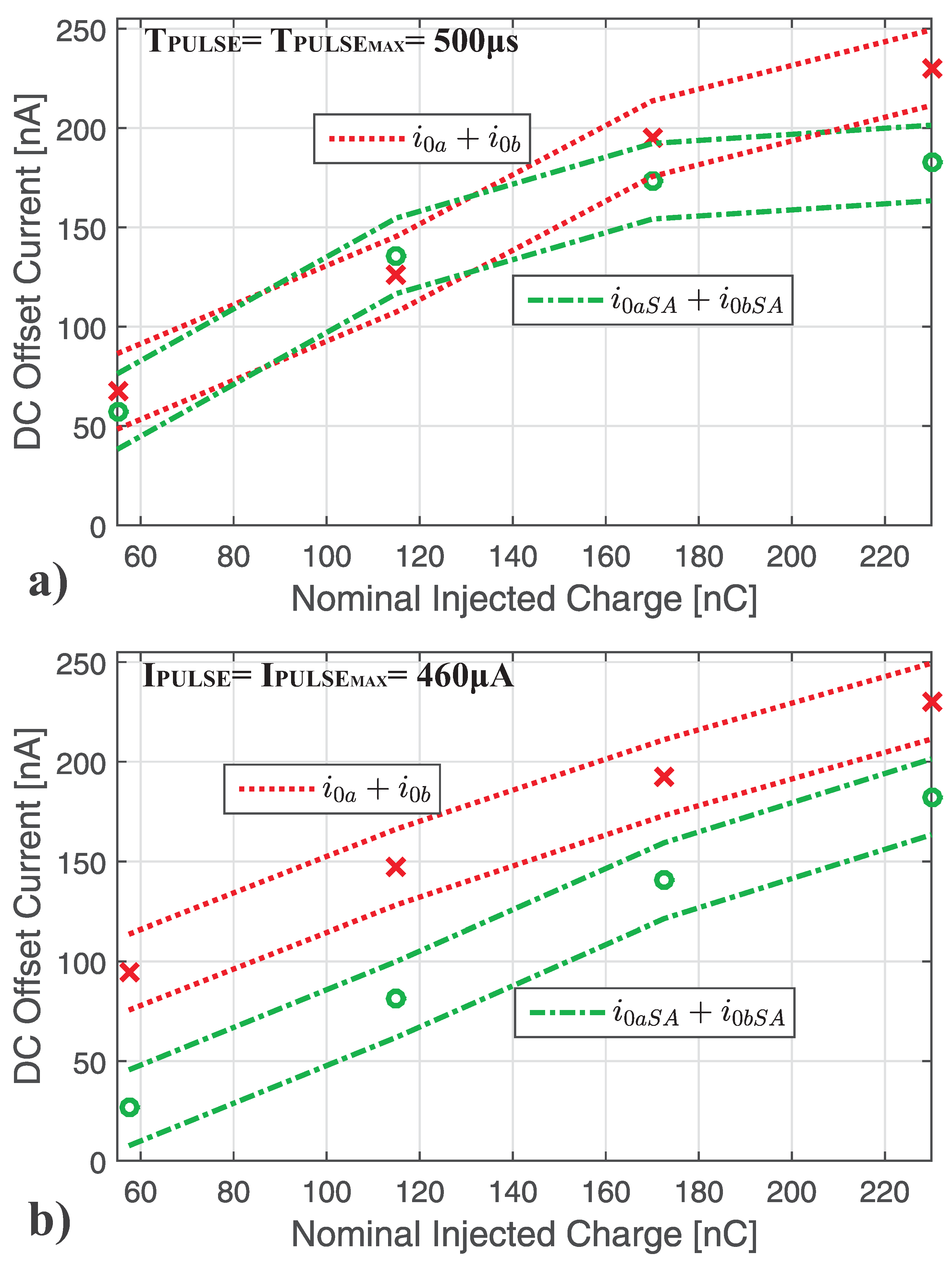
In Figure 12, the sum of the DC current offsets of the central electrodes of the two hexagonal stimulation sites operating simultaneously i 0 a + i 0 b (as shown in Figure 10) is compared with the sum of the DC offset currents of the same electrodes generated when each hexagonal site operates stand-alone i 0 a S A + i 0 b S A (as represented in Figure 11a,b). The nominal injected charge Q P U L S E = I P U L S E · T P U L S E versus the DC offset current for a constant stimulation current I P U L S E = I P U L S E M A X = 460 μ A (among dashed red lines for the sum of the two central electrodes DC offset currents i 0 a + i 0 b ) and for a constant pulse width T P U L S E = T P U L S E M A X = 500 μ s (among dash-dotted green lines for the sum of the two central electrodes DC offset currents i 0 a + i 0 b ).
The comparison shows that the presence of the return electrode shared among two active stimulation sites, is less effective in terms of DC offset current reduction than when it operates with an only hexagonal site alternately one after the other, so that:
i 0 a S A + i 0 b S A < i 0 a + i 0 b
In other words, assuming an equal number of active excitation sites per area for a defined amount of time, an excitation of adjacent sites operating alternately stand-alone generates less DC offset current than a static one. This suggests how a dynamic excitation of adjacent sites is intrinsically safer than a static one as concerns the DC offset current generation.

5. Conclusions

An automated test bench aimed at monitoring the nanoampere range DC offset current generated by platinum electrodes during biphasic stimulation in a saline bath was considered. Data storage redundancy to achieve high reliability in the measurement was implemented, and the overall procedures were described. The investigation in this paper showed how the presence of a big return electrode reduces the DC offset current. For a defined charge to be injected, DC offset current generation is related mostly to the timing of the biphasic stimulation in terms of its frequency and pulse width. In particular, for a defined injected charge needed to stimulate the tissues, lowering the frequency of the biphasic signal and a shortened pulse width reduce its DC offset current. Moreover, for the same injected charge, the sum of the DC offset currents due to the solitary activation of two hexagonal stimulation sites is always lower than the DC offset currents due to two hexagonal stimulation sites activated simultaneously. This experimental evidence suggests how the more dynamic is the stimulation pattern among the different stimulation sites with a shortened biphasic pulse width, the more safety compliant the stimulation is, as less DC offset currents are spread into the tissues.
DC offset currents depend on the voltage offset of the platinum electrodes and on the input/output impedance of the current sources (stimulator branches). Even though the stimulator is perfectly charge balanced and has an infinite input impedance, the mismatch between the macroscopic electrode-tissue interfaces generates DC offset currents in a comprehensive and realistic scenario during a biphasic stimulation. Therefore, precise verification tests as those described in this paper are needed to evaluate the effective DC offset current due to the biphasic stimulation. This is to address the electrical parameter constraints needed to guarantee the safe operating condition required by assessing the implantees’ safety.

Funding

This work has been supported by the Department of Education and Training of the Australian Government in the framework of the 2016 Endeavour Research Fellowship granted to Dr. Aiello.

Acknowledgments

The author thanks Prof. Nigel Lovell, Prof. Torsten Lehmann and the Bionic Vision Australia staff of the University of New South Wales (UNSW), Sydney, Australia, for their support.

Conflicts of Interest

The author declares no conflict of interest.

References

  1. Lilly, J.; Hughes, J.; Alvord, E.; Galkin, T. Brief, Noninjurious Electric Waveform for Stimulation of the Brain. Science 1955, 121, 468–469. [Google Scholar] [CrossRef] [PubMed] [Green Version]
  2. Huang, C.Q.; Carter, P.M.; Shepherd, R.K. Stimulus induced pH changes in cochlear implants: An in vitro and in vivo study. Ann. Biomed. Eng. 2001, 29, 791–802. [Google Scholar] [CrossRef] [PubMed]
  3. Merrill, D.R.; Bikson, M.; Jefferys, J.G. Electrical stimulation of excitable tissue: Design of efficacious and safe protocols. J. Neurosci. Methods 2005, 141, 171–198. [Google Scholar] [CrossRef] [PubMed]
  4. John, S.E.; Shivdasani, M.N.; Leuenberger, J.; Fallon, J.B.; Shepherd, R.K.; Millard, R.E.; Rathbone, G.D.; Williams, C.E. An automated system for rapid evaluation of high-density electrode arrays in neural prostheses. J. Neural Eng. 2011, 8, 036011. [Google Scholar] [CrossRef] [PubMed]
  5. Brummer, S.B.; Turner, M.J. Electrical stimulation with pt electrodes. II. estimation of maximum surface redox (theoretical nongassing) limits. IEEE Trans. Biomed. Eng. 1977, BME-24, 440–443. [Google Scholar] [CrossRef] [PubMed]
  6. Aran, J.M.; Wu, Z.Y.; Cazals, Y.; de Sauvage, R.C.; Portmann, M. Electrical stimulation of the ear: Experimental studies. Ann. Otol. Rhinol. Laryngol. 1983, 92, 614–620. [Google Scholar] [CrossRef] [PubMed]
  7. Hurlbert, R.J.; Tator, C.H.; Theriault, E. Dose-response study of the pathological effects of chronically applied direct current stimulation on the normal rat spinal cord. J. Neurosurg. 1993, 79, 905–916. [Google Scholar] [CrossRef] [PubMed]
  8. Shepherd, R.K.; Linahan, N.; Xu, J.; Clark, G.M.; Araki, S. Chronic electrical stimulation of the auditory nerve using non-charge-balanced stimuli. Acta Otolaryngol. 1999, 119, 674–684. [Google Scholar] [CrossRef] [PubMed]
  9. Xu, J.; Shepherd, R.K.; Millard, R.; Clark, G.M. Chronic electrical stimulation of the auditory nerve at high stimulus rates: A physiological and histopathological study. Hear Res. 1997, 105, 1–29. [Google Scholar] [CrossRef]
  10. Franke, M.; Bhadra, N.; Bhadra, N.; Kilgore, K. Direct current contamination of kilohertz frequency alternating current waveforms. J. Neurosci. Methods 2014, 232, 74–83. [Google Scholar] [CrossRef] [Green Version]
  11. Huang, C.Q.; Shepherd, R.K.; Carter, P.M.; Seligman, P.M.; Tabor, B. Electrical stimulation of the auditory nerve: Direct current measurement in vivo. IEEE Trans. Biomed. Eng. 1999, 46, 61–470. [Google Scholar] [CrossRef] [PubMed]
  12. Carter, P.; Money, D. Feedback System to Control Electrode Voltages in a Cochlear Stimulator and the Like. U.S. Patent US5674264, 7 October 1996. [Google Scholar]
  13. Huang, C.Q.; Shepherd, R.K.; Seligman, P.M.; Clark, G.M. Reduction in excitability of the auditory nerve following acute electrical stimulation at high stimulus rates. III. capacitive versus non-capacitive coupling of the stimulating electrodes. Hear. Res. 1998, 116, 55–64. [Google Scholar] [CrossRef]
  14. Dommel, N.; Wong, Y.T.; Lehmann, T.; Dodds, C.W.; Lovell, N.H.; Suaning, G.J. A CMOS retinal neurostimulator capable of focused, simultaneous stimulation. J. Neural Eng. 2009, 6, 035006. [Google Scholar] [CrossRef] [PubMed]
  15. Greenwald, E.; Maier, C.; Wang, Q.; Beaulieu, R.; Etienne-Cummings, R.; Cauwenberghs, G.; Thakor, N. A CMOS Current Steering Neurostimulation Array With Integrated DAC Calibration and Charge Balancing. IEEE Trans. Biomed. Circuits Syst. 2017, 11, 324–335. [Google Scholar] [CrossRef] [PubMed]
  16. Luo, Z.; Ker, M. A High-Voltage-Tolerant and Precise Charge-Balanced Neuro-Stimulator in Low Voltage CMOS Process. IEEE Trans. Biomed. Circuits Syst. 2016, 10, 1087–1099. [Google Scholar] [CrossRef] [PubMed]
  17. Lehmann, T.; Chun, H.; Preston, P.; Suaning, G. Current-limited passive charge recovery for implantable neuro-stimulators: Power savings, modelling and characterisation. In Proceedings of the 2010 IEEE International Symposium on Circuits and Systems, Paris, France, 30 May–2 June 2010; pp. 3128–3131. [Google Scholar]
  18. Chun, H.; Yang, Y.; Lehmann, T. Safety ensuring retinal prosthesis with precise charge balance and low power consumption. IEEE Trans. Biomed. Circuits Syst. 2013, 8, 108–118. [Google Scholar] [CrossRef] [PubMed]
  19. Rose, T.L.; Robblee, L.S. Electrical stimulation with Pt electrodes. VIII. Electrochemically safe charge injection limits with 0.2 ms pulses. IEEE Trans. Biomed. Eng. 1990, 37, 1118–1120. [Google Scholar] [CrossRef] [PubMed]
  20. Linear Technology. Single Resistor Gain Programmable, Precision Instrumentation Amplifier. Technical Data. Available online: http://cds.linear.com/docs/en/datasheet/1167fc.pdf (accessed on 23 July 2020).
  21. Analog Device. LC2MOS 16-Channel High Performance Analog Multiplexers, Technical Data. Available online: http://www.analog.com/media/en/technical-documentation/data-sheets/ADG406_407_426.pdf (accessed on 23 July 2020).
  22. Moghadam, G.K.; Wilke, R.; Suaning, G.J.; Lovell, N.H.; Dokos, S. Quasi-monopolar stimulation: A novel electrode design configuration for performance optimization of a retinal neuroprosthesis. Public Libr. Sci. 2013, 8, 73130. [Google Scholar] [CrossRef] [PubMed] [Green Version]
  23. Wong, Y.T.; Dommel, N.; Preston, P.; Hallum, L.E.; Lehmann, T.; Lovell, N.H.; Suaning, G.J. Retinal Neurostimulator for a Multifocal Vision Prosthesis. IEEE Trans. Neural Syst. Rehabil. Eng. 2007, 150, 425–434. [Google Scholar] [CrossRef] [PubMed]
  24. Matteucci, P.B.; Chen, S.C.; Dodds, C.; Dokos, S.; Lovell, N.H.; Suaning, G.J. Threshold analysis of a quasimonopolar stimulation paradigm in visual prosthesis. In Proceedings of the 2012 Annual International Conference of the IEEE Engineering in Medicine and Biology Society, San Diego, CA, USA, 28 August–1 September 2012; pp. 2997–3000. [Google Scholar]
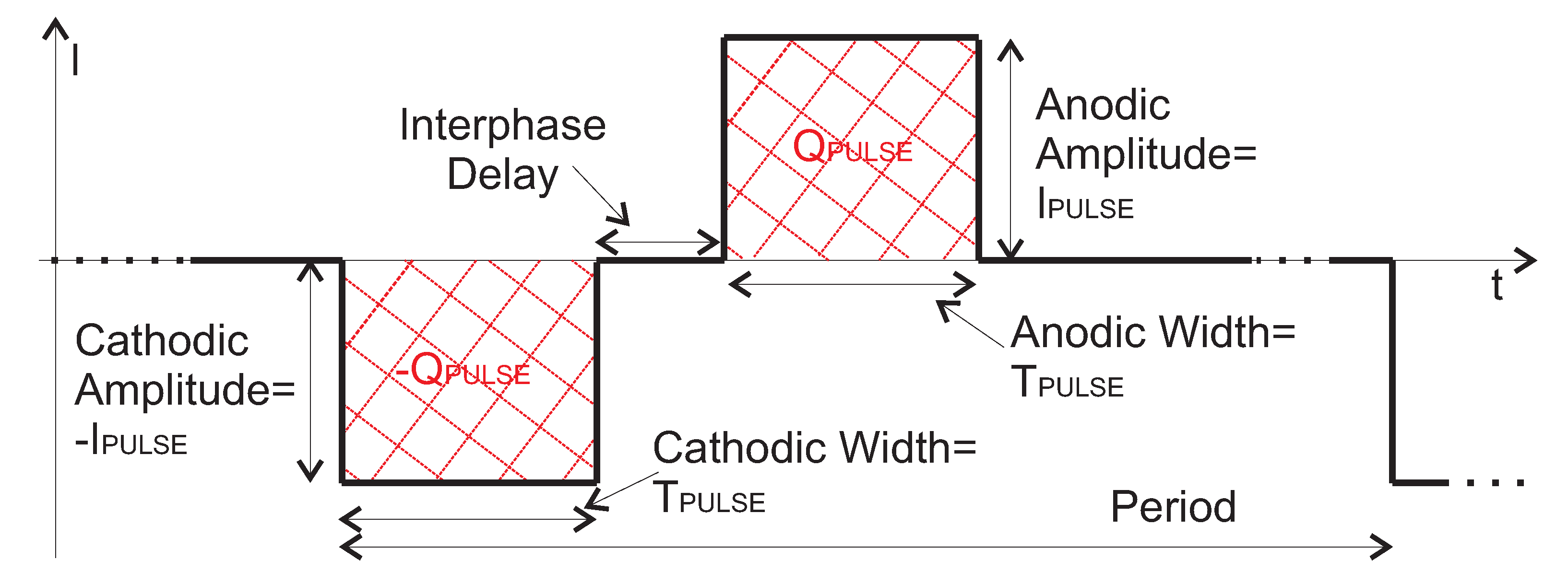
Figure 1. Pictorial representation of a biphasic current stimulation. Typical electric characteristics are highlighted.
Electronics 09 01198 g001
Figure 2. (a) Sketch of the DC offset current measurement test bench. (b) Respective photo.
Electronics 09 01198 g002
Figure 3. DC offset current measurement setup inside the metal enclosure as depicted in Figure 2.
Electronics 09 01198 g003
Figure 4. Sketch of the DC offset current detection test board.
Electronics 09 01198 g004
Figure 5. (a) Photo of the 24 electrode matrix (E24015) used in the DC offset current measurement setup [22]. (b) Saline bath.
Electronics 09 01198 g005
Figure 6. Sketch of (a) All Adjacent (AA) and (b) Hex Quasi-monopolar (HQ) return stimulation patterns with the respective current pulses’ directions and the return electrode (RE).
Electronics 09 01198 g006
Figure 7. Biphasic current amplitude versus DC offset current ( ± 3 σ range around the average value defined by the dashed and dash-dotted lines) for All Adjacent (AA: × for the central current i 0 ; 🟉 for the sum of the other surrounding currents) and Hex Quasi-monopolar (HQ: + for the central current i 0 ; ⋄ for the sum of the other surrounding currents) stimulation patterns at 50 Hz. Single hexagon (HEXa). Pulse width constant equal to T P U L S E = T P U L S E M A X = 500 μ s .
Electronics 09 01198 g007
Figure 8. Sketch of a Hex Quasi-monopolar (HQ) return stimulation pattern using two active hexagon (HEXa and HEXb) according to the electrode matrix shown in Figure 5.
Electronics 09 01198 g008
Figure 9. Hexagon HEXa and HEXb excitations according to the stimulation pattern in Figure 8. (a) Biphasic current amplitude I P U L S E versus DC offset current ( ± 3 σ range around the average value defined by dashed and dash-dotted lines) for the Hex Quasi-monopolar (HQ) stimulation pattern at 50 Hz (see ×) and 25 Hz (see +). Pulse width constant equal to T P U L S E = T P U L S E M A X = 500 μ s . (b) Biphasic pulse duration T P U L S E versus DC offset current ( ± 3 σ range around the average value defined by dashed and dash-dotted lines) for the Hex Quasi-monopolar (HQ) stimulation pattern at 50 Hz (see ×) and 25 Hz (see +). Pulse amplitude constant equal to I P U L S E = I P U L S E M A X = 460 μ A .
Electronics 09 01198 g009
Figure 10. Hexagon HEXa and HEXb excitations according to the stimulation pattern in Figure 8. Nominal biphasic charge Q P U L S E versus DC offset current ( ± 3 σ range around the average value defined by dashed and dash-dotted lines) for a constant current pulse I P U L S E = I P U L S E M A X = 460 μ A (dashed red lines around ×) and for constant pulse duration T P U L S E = I P U L S E M A X = 500 μ s (dash-dotted black lines around 🟉). Multiple hexagon excitation (HEXa and HEXb) for a Hex Quasi-monopolar (HQ) stimulation pattern at 50 Hz.
Electronics 09 01198 g010
Figure 11. Sketch of Hex Quasi-monopolar (HQ) return stimulation patterns using (a) the hexagonal site HEXa operating stand-alone (SA) and the return electrode (RE) or (b) the hexagonal site HEXb operating SA and the RE.
Electronics 09 01198 g011
Figure 12. Hex Quasi-monopolar (HQ) stimulation pattern as in Figure 11a,b at 50 Hz. Comparison between the current source to the hexagonal site HEXa and HEXb excited simultaneously (×: i 0 a + i 0 b in Figure 8) and the sum of the current source to a hexagonal site activated stand-alone (SA) (∘: i 0 a S A + i 0 b S A in Figure 11). (a) Nominal injected charge Q P U L S E versus DC offset current ( ± 3 σ range around the average value defined by dashed and dash-dotted lines) for a pulse width constant equal to T P U L S E M A X = 500 μ s . (b) Nominal injected charge Q P U L S E versus DC offset current ( ± 3 σ range around the average value defined by dashed and dash-dotted lines) for a stimulation current constant equal to I P U L S E = I P U L S E M A X = 460 μ A .
Electronics 09 01198 g012