1. Introduction
Stroke is a major cause of disability in the world. In 2017 there were approximately 12 million strokes globally [
1]; prevalence is increasing due to improved longevity and rising obesity-related lifestyle factors (e.g., hypertension). Approximately 40% of stroke survivors are left with some loss of arm function as a result of their stroke [
2]. Repetitive task-oriented training has been shown to help recovery as part of a rehabilitation programme [
3] and one of the most prevalent technologies used to assist in rehabilitation is Functional Electrical Stimulation (FES) [
4]. This method uses pulses of electrical current passing through underlying nerves, thereby causing the user’s muscles to contract and generate movement. By repeated use of FES to facilitate task practice, some users may regain functional movement [
5] in the affected limbs.
The SMARTmove project [
6], funded by the UK Medical Research Council (MRC), realised a new FES system which provided high selectivity stimulation of the muscles used in hand, wrist and arm movements. The wearable system created by the SMARTmove project is the first example of combining a fabric FES array, a non-contact feedback sensor, and a controller able to precisely adjust stimulation using dynamic models of the arm. Although this wearable system is specifically designed for stroke survivors, who often exhibit movement dysfunction in one or more affected limbs, it can also be used in the rehabilitation of other neurological conditions (e.g., spinal cord injuries, multiple sclerosis) to restore lost or impaired movement.
Current commercial FES systems primarily use two pairs of large electrodes (typically of the order of 5 cm × 5 cm in size), giving the ability to drive two groups of muscles, but these are unable to produce selective movement such as fine finger-level gestures. A few commercial systems such as the Bioness-H200, are able to more selectively drive several groups of muscles allowing for more precise gestures; the Bioness-H200 can control five different muscles in the hand/wrist. Academic research developing transcutaneous multi-pad electrodes and arrays has been driven by the University of Belgrade [
7], ETH Zurich [
8], the Swiss Federal Institute of Technology Lausanne [
9], Sheffield Hallam University [
10], together with Fatronik-Tecnalia [
11]. The layout of electrode arrays often assumes a generic pattern, and is typically used to allow the placement of a virtual electrode at any location within the array [
12]. Such solutions, however, are only able to control a few of these points at a time using sequential stimulation; this limits the ability to produce complex gestures. Other systems employ a multi-pad electrode layout which is designed to match the geometry of underlying muscles, however, these require precise alignment. In both cases of electrode layout, electrodes are activated in an open-loop fashion, and do not receive real-time position feedback to correct the resulting motion.
Existing systems also have limitations in terms of the electrode construction which restricts usability. The first widely-used approach uses embroidered conductive thread resulting in a rough electrode surface which causes an uneven current distribution, leading to discomfort when the stimulation current is high. In addition, embroidered high density conductive areas such as electrodes are stiff. The second widely-used approach uses gel electrodes on plastic substrates which are not sufficiently flexible, breathable, or comfortable.
The SMARTmove project has created a new FES system to address the limitations of existing FES techniques. By using an array of small electrodes, rather than a pair of large electrodes, a high level of selectivity in the stimulated muscles has been achieved. Independent control of smaller electrodes also enables more individual muscles to be activated simultaneously, thus increasing the range of achieved gestures. By using real-time feedback and an iterative learning control approach, the system can help the user achieve precise movements while adapting to their physiology, rather than being limited to a set of fixed stimulation patterns. This allows the stimulation to be better tailored to the user’s progress and condition and avoids the need for exact electrode positioning. The printed dry fabric electrode array also makes the system easier to don/doff and avoids issues that arise with gel electrodes, such as drying out, susceptibility to contamination, and a short life time (typically 1 to 2 weeks). The fabric electrode array is more flexible and comfortable. It is also washable and reusable, and therefore cost effective for long term use.
This paper focuses on the design of the stimulation electronics used in the SMARTmove system. A review of stimulation electronics output stages for FES has been carried out by Souza [
13]. The applied stimulation can be grouped into two general categories: monophasic where the stimulation pulses only have one polarity; and biphasic where the stimulation pulses have both positive and negative polarities. The stimulator design reported in this paper uses biphasic stimulation as this reduces the potential for skin burns and tissue damage [
14] and provides a wider range of stimulation profiles when compared to monophasic stimulation. Of the biphasic designs investigated, the majority use H-bridge drivers for controlling the phase of the stimulation. However, this requires a pair of electrodes for each stimulation channel. Other non H-bridge designs often also require control of both the source and return of each channel, such as that by Huerta [
15]. Where a common return electrode is used, as is the case when using an array, each channel needs to be able to generate both positive and negative stimulation voltages rather than swapping the polarity of the electrodes, as typically occurs with simple electrode pairs.
Existing FES stimulator designs are also often based around discrete components rather than using an integrated package, thereby increasing the circuit board space required for each channel. Many existing designs also use an isolation transformer on the output to provide an isolation barrier; these transformers often have a significant footprint which leads to a large implemented size when there are multiple channels.
Using existing solutions for FES stimulation would result in a bulky and complex stimulator that would be unsuitable for wearable use. To overcome these limitations the developed design uses off the shelf multichannel high voltage switchIntegrated circuits (ICs) combined with discrete current limiting and dc blocking circuitry for the stimulation frontend. Pulse timing is controlled by Field Programmable Gate Array (FPGA) based logic which is in turn controlled by a microprocessor to manage communication with the software managing the stimulation profiles. These provide greater parameter control than previous designs with a low cost and a small size suitable for wearable deployment.
In this paper we discuss, in
Section 2, the constituent parts and operation of the rehabilitation solution as a whole. The designed electronics that make up the multichannel biphasic stimulator is discussed in
Section 3.
Section 4 presents system use and testing on both healthy individuals and stroke survivors, illustrating use of the system to stimulate individual finger movements to produce a range of gestures. Finally, conclusions are provided.
2. Complete System: Components and Operation
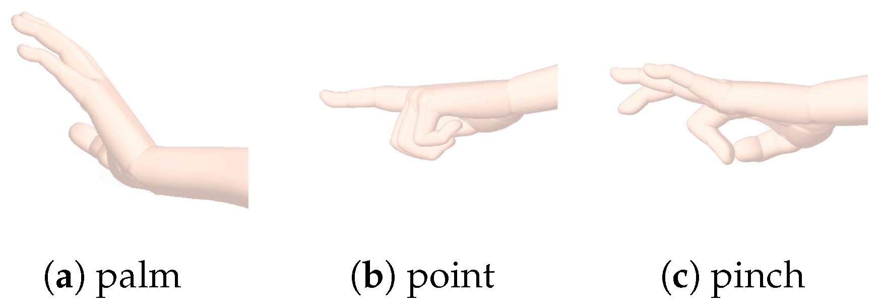
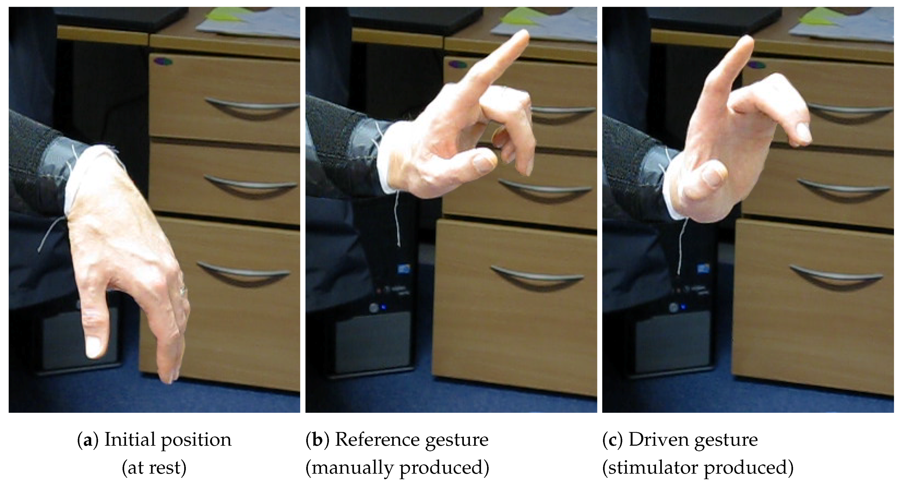
The SMARTmove system is designed to allow stroke survivors to practice a series of commonly undertaken tasks at home with the assistance of electrical stimulation, as part of their rehabilitation programme. Currently the system supports three different gestures (see
Figure 1): palm flattening, pointing and pinching. These gestures form the basis for functional activities such as closing a drawer or operating a light switch.
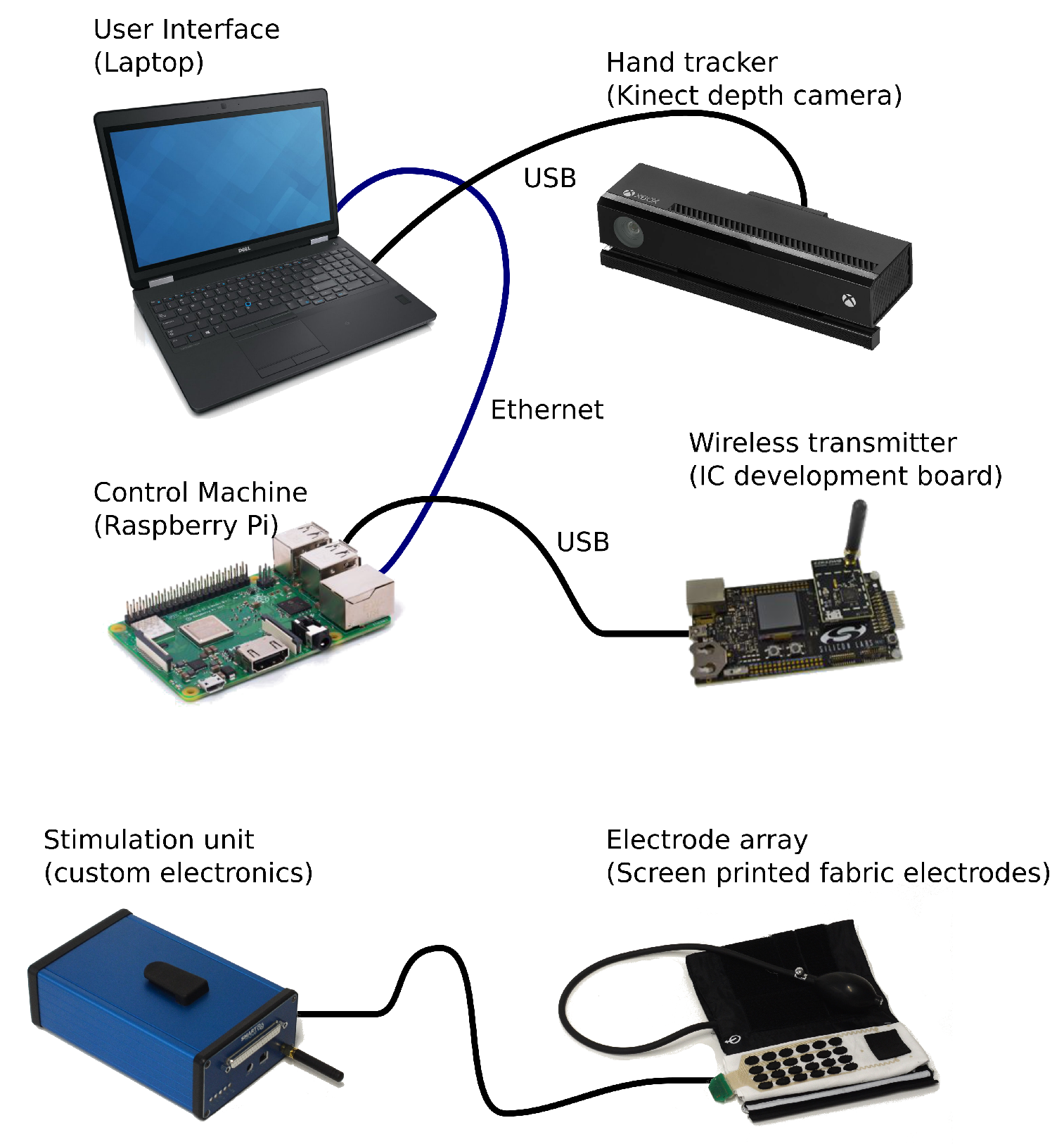
The SMARTmove system contains several components that work together to control and deliver the electrical stimulation. A graphical overview of the system components can be seen in
Figure 2.
The SMARTmove system uses a commercial, off the shelf, depth camera (Microsoft Kinect v2) to capture the movements of a user’s hand. The depth information from the camera is processed on a laptop to extract the angular position of the user’s hand and fingers. This processing is performed by a standalone application which then streams the data into the Graphical User Interface (GUI) application also running on the user’s laptop.
The GUI provides the interface for the user to control the system. After initial configuration of the system a series of tasks of increasing complexity are presented to the user. The system uses a gamification approach to the rehabilitation process by enabling users to progress from task to task once they have gained enough points in a given task. These points are based on how well they perform a task using performance metrics, such as the accuracy of the final gesture and the smoothness of movement. This means that the user will progress onto the later tasks more quickly once they have become more proficient in the earlier tasks. The GUI application translates the user’s interactions into a series of commands for the control software and displays the returned feedback information to the user after every task.
The control system [
16] runs on a separate Raspberry Pi low-cost computer and receives the commands and hand tracking data from the GUI on the laptop. This is achieved using a network connection over a wired Ethernet link. The software has a map of which electrode causes which group of hand joint angles to move, and by how much. This map is automatically generated by monitoring the movement during an array identification sequence (described further in
Section 4.1). An iterative learning controller is used in the control system, allowing it to improve the user’s response by adjusting the delivered stimulation based on previous results. The stimulation levels which are calculated by the controller forty times a second are then sent over USB to the wireless transmitter which relays them wirelessly to the stimulator unit electronics (described in detail in
Section 3).
The stimulation pulses are delivered to the user through a fabric electrode array [
17], connected via a cable to the stimulation unit. This array consists of screen printed dry electrodes in a six by four pattern, giving twenty four stimulation electrodes in total, together with an additional large common return electrode. The electrode array is attached to a cuff which is placed on the arm and secured using a hook and loop fastener. The cuff applies pressure to the electrode array ensuring good contact between the electrodes and the user’s skin.
3. Stimulator Unit: Electronics Design and Implementation
3.1. Overview
The stimulator unit converts the stimulation levels sent from the control software into the electrical stimulation pulses. Each set of levels from the controller triggers a single set of synchronised pulses from the unit. Each of the twenty four independent stimulation channels can have a different stimulation intensity level, including the possibility of zero stimulation. The stimulator uses voltage controlled stimulation in a multichannel configuration with varying pulse length used to adjust the stimulation intensity of each channel. Each channel has an independently controllable pulse width and waveform, adjustable on every pulse. The stimulation voltage is common across all the electrodes but is variable between 50 V and 100 V DC.
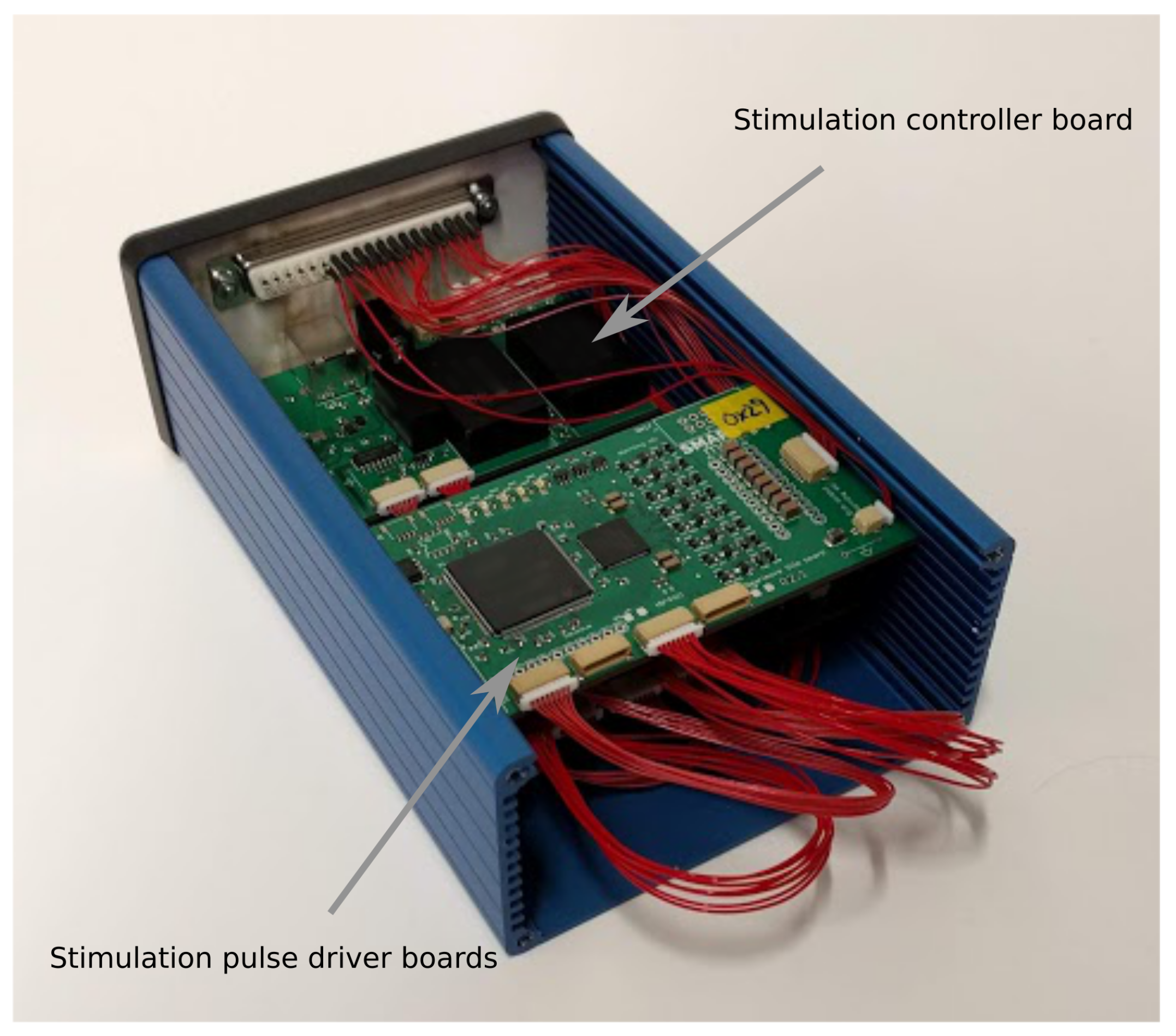
The design is implemented using a series of interconnected modules split across several custom printed circuit boards (PCBs). The modules are separated into a control board together with sufficient eight channel driver boards to produce the required number of stimulation channels. The setup for the SMARTmove system uses three driver boards to achieve twenty four channels. These boards are slotted inside a compact enclosure, shown in
Figure 3, which can be worn, for example, on the user’s belt. The boards are connected together with a series of short cable harnesses. The stimulator is connected to the fabric electrode array worn on the arm using a detachable multicore cable.
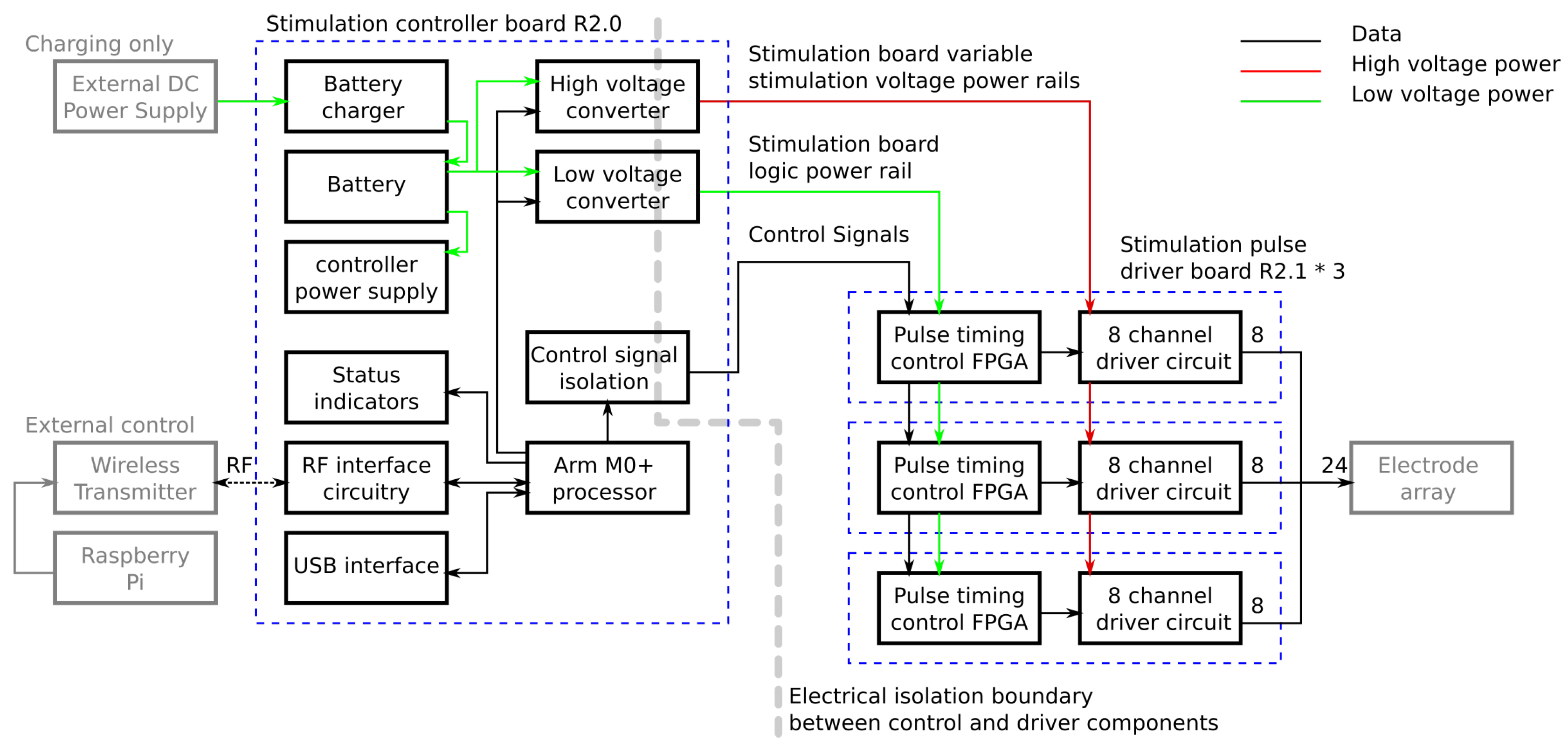
Figure 4 is a schematic showing the functionality implemented on each board.
3.2. Stimulation Controller Board
The controller board contains the modules for managing the system and passing commands from the control program to the driver boards. Commands are received from the control software running on the Raspberry Pi either over a USB cable or via a wireless link from a USB attached transmitter. Commands are processed by an ARM M0+ microprocessor which has inbuilt USB and wireless connectivity. Each stimulation request from the control program defines a single set of pulses, one for each channel, with forty stimulation requests being sent per second. Each set of pulses is defined separately which allows the length of every pulse to be varied, and prevents stimulation continuing should the connection to the Raspberry Pi be lost. When a message is received it is checked for corruption and, if it is valid, it is decoded into the pulse lengths for each channel and the voltages for the stimulation power supplies. The high voltage power supplies are reconfigured to provide a new stimulation voltage if it has changed. The pulse lengths for each channel are then sent to the corresponding driver over an IC interface. In order to keep the pulses synchronised, a dedicated start signal is used which triggers all of the drivers to start the pulses at the same time.
Another major function of the control board is management of the power supplies. To provide for wireless operation an internal battery is used to power the stimulator and all other required voltages are generated from this. The battery, which provides approximately four hours of active use, is charged using an external 9 V DC external power supply which can also be used to power the unit. Internal power regulators take either the battery voltage or DC input voltage and generate 3.3 V DC for the microprocessor and a switchable 5 V DC supply for powering the rest of the system.
The stimulation voltage is generated using a pair of isolated variable DC-DC voltage converters which take the power from the 5V power rail and produce between 50 V and 100 V DC which is selectable by the controller for each pulse. The DC-DC converters sit across an isolation boundary which separates the low voltage interface circuitry on the board from the high voltage stimulation circuitry located on the other boards. This boundary adds two safety features. In the event of major damage to the driver boards the high stimulation voltages cannot appear on any of the interface connectors. In addition, current cannot flow between the electrode interface and any of the other connectors on the unit. This means the stimulation current will only flow between the stimulation electrodes and the return electrode and will not take any unwanted paths through the user to an interface connector if touched. Power for the low voltage circuitry on the driver boards is generated by another isolated DC-DC converter at 5 V DC. Control signals for the driver boards are passed through optical isolation ICs in order to maintain the isolation barrier.
3.3. Stimulation Pulse Driver Board
The stimulation pulse’s driver boards receive pulse length settings and triggering from the control board and produce the required pulses. Each pulse is made up of a variable length positive pulse followed by a variable length negative pulse. The electrode is then actively driven to 0 V after each pulse, where it remains until the next pulse.
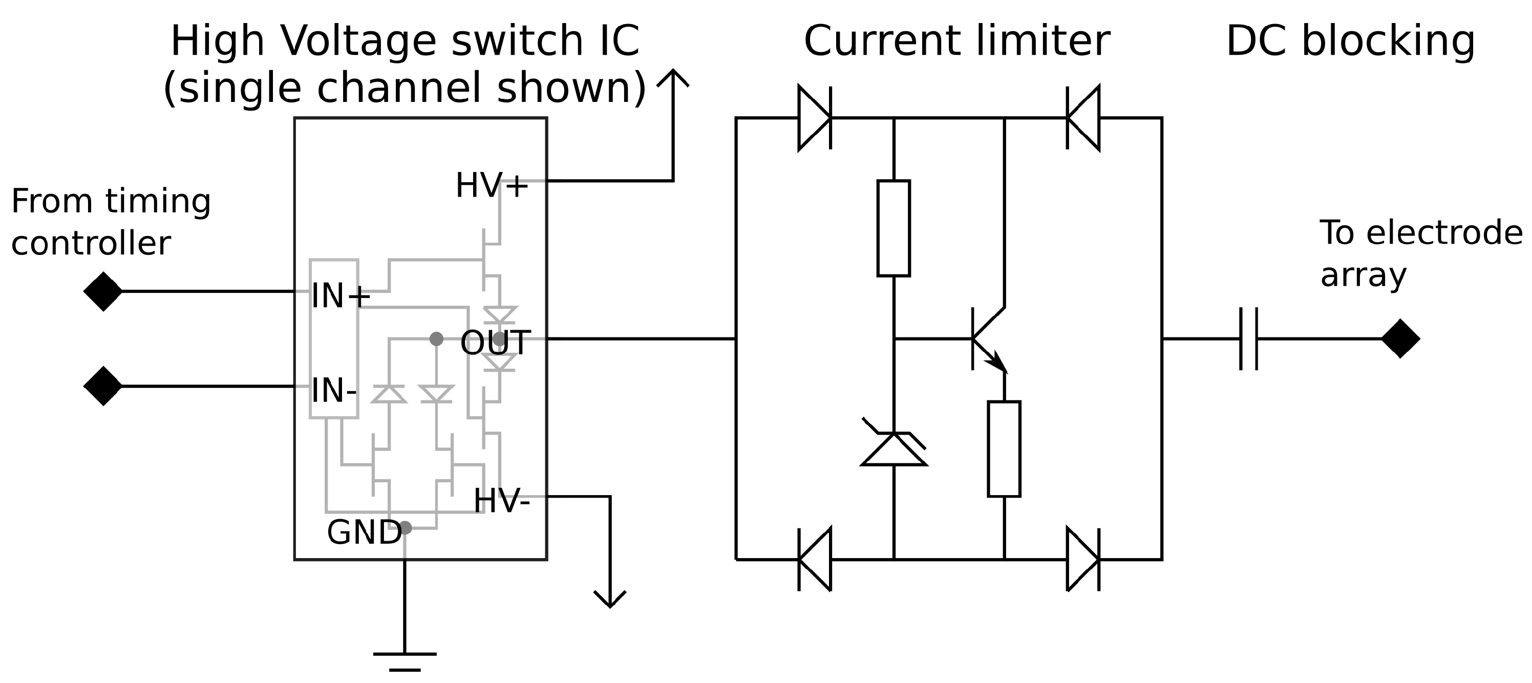
The pulse drive circuitry, which generates the initial pulse waveform, consists of a constant voltage pulse generator which is capable of operating at high voltages. The pulse output is passed through a current limiting circuit and a DC blocking capacitor. The connections between the components can be seen in
Figure 5.
The pulse generator uses a commercially available high voltage switch integrated circuit (IC). This IC contains a Field Effect Transistor (FET) based switch stage along with the circuitry to control the gates from logic level input signals. Each of the eight outputs can be driven to one of three states (+V, Gnd, −V) in any combination. This creates the positive and negative pulses as well as an active return to ground when not producing a pulse. Using an off the shelf IC provides a very compact implementation which fits in a 10 mm by 10 mm package.
In order to achieve user safety, protective circuitry is added to the output of each channel. Current limiting circuitry is placed after every output to prevent large stimulation currents from flowing if there is a low resistance path through the user. A Zener diode based current limiter is set to a 9 mA limit and placed within a diode bridge to limit the current in either direction. The final component in the pulse path is a DC blocking capacitor which prevents any DC voltage appearing on the electrodes which could potentially cause electrical burns in the event of hardware failure. These nine extra components per channel require minimal board space, each taking 80 mm2 of PCB surface area per channel. Once the driver IC and routing space to link the parts together are taken into account the required area is still very low; the eight channel driver along with the required extra circuitry will fit in an area of 20 mm × 35 mm assuming a 4-layer PCB, of which 16 mm × 20 mm comprises the extra safety circuitry. The integrated driver design also reduces the cost of the stimulator compared with using discrete control transistors for each channel.
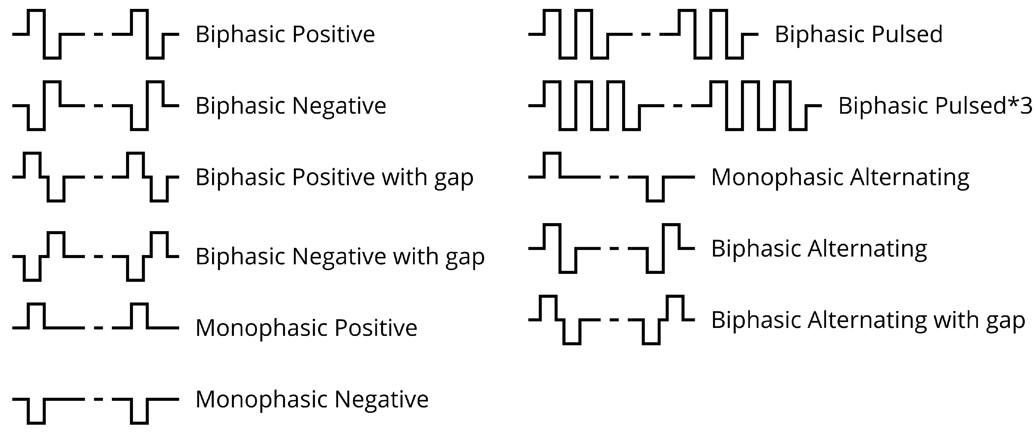
The pulse generator is driven by a timing controller which controls the pulse lengths on each channel. The timing controller is implemented on a Field Programmable Gate Array (FPGA) which contains an output control block for each output and a communication module to provide an interface to the controller board. In the developed design each driver IC has its own control FPGA in order to allow the number of channels to be easily altered if required. In a less flexible hardware configuration a control FPGA could control multiple driver ICs to reduce cost/size. The output control block contains a high accuracy timer and state machine which cycles through the required stages of the pulse. The control blocks in the FPGA have several waveforms available allowing them to produce a range of output pulse waveforms as can be seen in
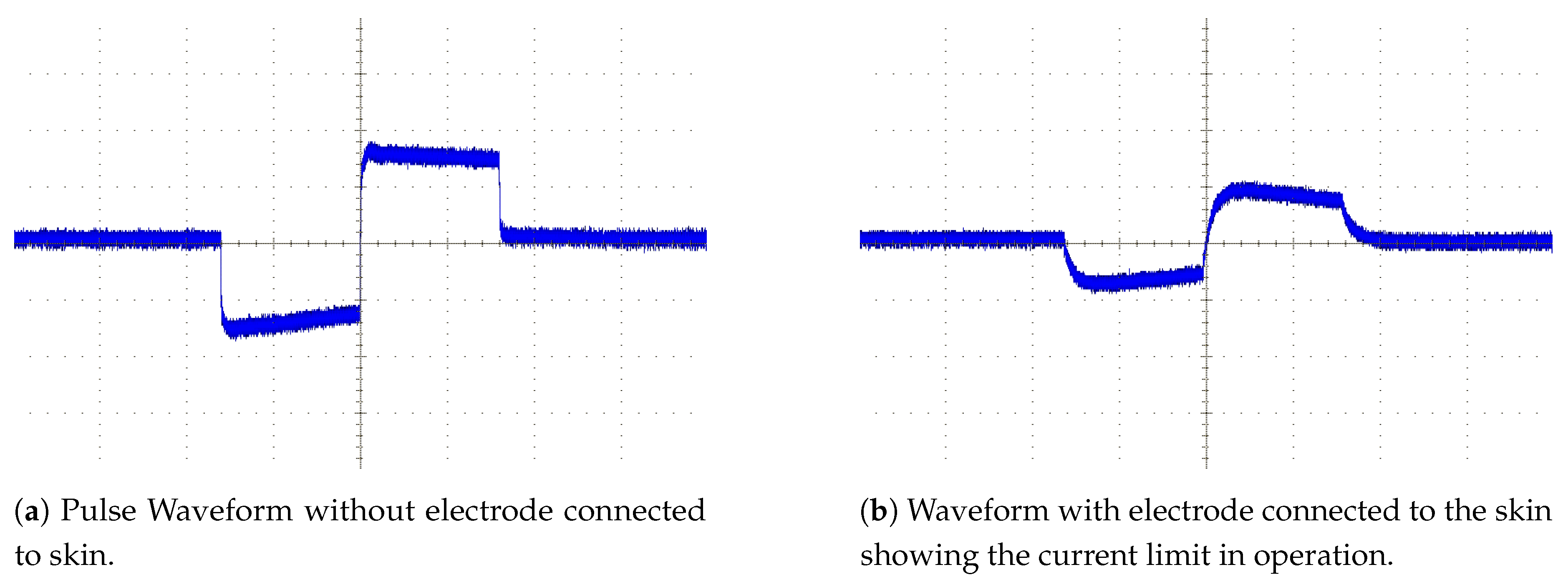
Figure 6. The default mode used in the majority of the tests to date was the biphasic negative mode which uses a matched pair of pulses where the negative pulse is immediately followed by a positive pulse as shown in
Figure 7.
The controller board interface is in two parts. The pulse lengths are sent to the drivers using the isolated I
C interface on the control board. The controller addresses each of the driver boards in turn sending them the settings for each channel for the next pulse. The start trigger signal is then sent using a dedicated logic signal to all boards at once. This allows all the boards to trigger the output control blocks thus starting their outputs close to simultaneously. Differences in timing of up to 20 ns between the outputs of different driver boards are possible as the FPGA clocks are not synchronised but this is negligible compared to the typical pulse lengths of 60
s to 500
s. A simplified block diagram showing how these interface with the rest of the components in the timing controller can be found in
Figure 8.
5. Conclusions
The new design for a multichannel biphasic stimulator discussed in this paper unlocks the possibility of achieving compact and low cost multichannel stimulators which are suitable for wearable deployment. In addition, tests show the device to be capable of generating the desired specificity and control over stimulation allowing complex multiple muscle gestures to be produced.
The use of an integrated high voltage driver simplifies and reduces the size of the electronics compared to designs using discrete switching components. Only nine additional components are required per channel using only 80 mm2 of PCB surface area in total. This means the additional circuitry for an eight channel driver fits in a 16 mm by 20 mm section of double sided PCB. In total, once the driver IC and routing space to link the parts together are taken into account an entire eight channel driver stage can be implemented in an area of 20 mm by 35 mm of 4-layer PCB space. The low cost per channel of the drivers makes large channel count stimulators feasible in terms of component and material cost.
When tested on healthy users the stimulator design, in conjunction with the rest of the SMARTmove system, is capable of creating predictable, controlled, and selective movements. Tests on stroke survivors have produced mixed results, some subjects have been limited by either spasticity in the flexor muscles, or possibly changes in the reciprocal inhibition patterns, whereas others have shown less response to the stimulator and are expected to need a stronger level of stimulation or a different waveform to achieve sufficient movement to realise the target gestures. Refinements to the system are being investigated with the aim of increasing the movement in those who had a weaker response to the stimulation provided.

 ,
, 


